Embed Size (px)
Citation preview
Review
An overview of the recent advancesin spray-drying
Arun S. MUJUMDAR1, Li-Xin HUANG
2, Xiao DONG CHEN3*
1 National University of Singapore, Singapore 119260, Singapore2 Institute of Chemical Industries of Forestry Products, Nanjing 210042, P. R. China
3 Department of Chemical Engineering, Monash University, Clayton, Victoria, Australia
Received 31 August 2009 – Revised 11 February 2010 – Accepted 11 February 2010
Published online 26 April 2010
Abstract – A global overview is presented of recent developments in spray drying. Recent advancesin computational fluid dynamics modeling have provided new insights into the flow processesoccurring within the spray chamber. This is important since detailed experimental measurementswithin an operating spray dryer are almost impossible due to the hostile environment of high-temperature two-phase flow, which may be unsteady, and the high cost that would have to incur.Some recent predictive studies on predicted effects of innovative chamber geometry, reducedpressure operation, operation in low dew-point air and superheated steam are presented. Also, acomparison is made between steady and unsteady state computations to highlight the critical issues.Predicted results on a horizontal spray chamber configuration are also presented. Finally, a briefsurvey is made on the recent literature on spray freeze-drying as well as multi-stage drying processes.
computational fluid dynamics / modeling / spray drying / CFD
摘要 – 喷雾干燥技术的研究进展—综述○ 本文对近年来喷雾干燥技术的研究进展进行了全面的概述○ 近年来, 计算流体动力学模型为模拟喷雾室内流体流动过程提供了新的计算方法○ 由于干燥室内为高温下的两相流动体系, 因此这样环境下模拟和精确计算干燥过程的工作参数难度非常大○ 本文概述了采用预测模型的方法来预测干燥室的几何形状、减压操作、低雾化点下的操作以及过热蒸汽等因素对干燥工程的影响○ 同样, 稳态和非稳态计算方法的对比也是近年来研究的热点问题○ 作者还对水平喷雾干燥室构造的模拟和预测进行了论述○ 最后对新兴的冷冻喷雾干燥和多级干燥的文献进行了简单的综述○
计算流体动力学 / 模拟 / 喷雾干燥 / CFD
Résumé – Récentes avancées dans la conception et l’optimisation des installations de séchagepar pulvérisation : une vue d’ensemble. Un inventaire des récents développements dans ledomaine du séchage par pulvérisation est dressé. Les dernières avancées de la dynamique desfluides numérique ont permis d’obtenir de nouvelles représentations des processus d’écoulementayant lieu à l’intérieur de la chambre de séchage. Ces modélisations sont très importantes car desmesures expérimentales détaillées à l’intérieur d’une installation de séchage en fonctionnement sontpratiquement impossibles à réaliser, en raison des conditions hostiles liées au flux à températureélevée de deux phases, pouvant être irrégulier, et aux coûts qui seraient engendrés. Des étudesprédictives récentes sur les effets d’une géométrie innovante de la chambre, de conditions depression réduite, d’air à bas point de rosée et de vapeur surchauffée, sont notamment présentées.
*Corresponding author (通讯作者): [email protected]
Dairy Sci. Technol. 90 (2010) 211–224© INRA, EDP Sciences, 2010DOI: 10.1051/dst/2010015
Available online at:www.dairy-journal.org
Article published by EDP Sciences
Une comparaison des calculs réalisés dans des conditions stables ou instables est également réaliséeafin de mettre en lumière les points critiques. Les résultats de la prédiction pour une configurationde chambre horizontale sont présentés. Enfin, les dernières publications sur le couplage séchage parpulvérisation-lyophilisation et les procédés de séchage multi-étage sont présentées rapidement.
dynamique des fluides / modélisation / séchage par pulvérisation / CFD
1. INTRODUCTION
Because milk powder has many advanta-ges, e.g., long shelf-life due to low moisturecontent in the powder, low packing andtransport costs and facilitation of productutilization, it plays a significant role amongdairy products. For example, in France, in2000, the consumption of milk powderwas almost the same as that of fresh skimmilk. Spray drying converts liquid form intoan engineered powder product in one step.Such drying technology is also suitable todry many heat-sensitive products, e.g., dairyproducts, foods and pharmaceuticals, due tothe short drying time and ability to obtain apowder form product [8].
There are three main types of atomizersto convert a feed liquid stream into a sprayof droplets, i.e., pressure nozzle, two-fluidnozzle and centrifugal wheel atomizer [18].The selection of the atomization method isdependent on the product requirements aswell as initial feed physical properties.Recently, ultrasonic and electrostatic nozzleshave been reported to be used as atomizersin small-scale spray drying operations. Theycan produce a narrow size distribution ofdroplets for production of a mono-disperseproduct. For the contact of the drying med-ium and the atomized droplets, there arethree possible types of gas-droplet contact,i.e., counter-current, co-current and mixedflow. In co-current contact, the droplets pass-ing through the drying chamber move in thesame direction as the drying medium. In acounter-current operation, they flow inopposite directions and hence semi-dried ordried particles may be exposed to the dryingmedium at a higher temperature. This candamage thermo-sensitive powders, such as
milk products. Therefore, the majority ofdairy products are dried in concurrent spraydryers [45].
Spray drying chambers are mainly of thevertical type [3]. Vertical vessels with acylindrical cross-section and a conical bot-tom are used most frequently [36]. The sizeof the cylindrical and conical sectionsdepends on the application. Huang et al.[22, 24] have tested a horizontal spray dryer(HSD) as well as a two-stage horizontaldryer using the computational fluid dynamic(CFD) method. A few commercial opera-tions do use a horizontal layout but it is stillnot popular and its performance characteris-tics are not well understood yet.
O’Callaghan and Cunningham [42] havepointed out the need for the use of modernprocess control techniques in large-scalespray dryers and the use of “white box”models as opposed to the more traditional“black box” models. There is trend towardModel Predictive Control (MPC) whichrequires ability to forecast system behavioror response to upsets. Currently in milk pro-duction, empirical or semi-empirical modelsbased on past experience are used for con-trol purposes. Since the process involvedis highly nonlinear, it has the potential tolead to large uncertainties and thus produc-tion of off-spec products, which can be verycostly for large-scale plants. A “white box”model based on the fundamental equationsof conservation can be used to assist inMPC, as discussed by Verdurmen et al.[58]. As noted elsewhere the major deterrentto such modeling is the difficulty in detailedvalidation of CFD models due to the impos-sibility of obtaining local data within anoperating spray dryer even at a pilot scale.Most authors “validate” their CFD results
212 A.S. Mujumdar et al.
using only outlet data in an averaged man-ner. This does not represent true validationsince compensating errors within the cham-ber computations can yield a good match atthe outlet of the chamber. In principle, it ispossible to model the effects of stickiness,agglomeration, etc., using CFD models butsuch models do depend necessarily on alot of empirical input and hence muchuncertainty.
Although spray drying is used in manyindustries, fundamental understanding is stilllacking. For example, the design of spraydrying is probably still dependent on thedesigner’s experience and/or extensivepilot-scale testing. Even so, droplet/particledeposition on the chamber walls is highlyundesirable problem. In this paper, an over-view is presented of the recent developmentsin spray drying technology including thefundamentals and applications of spray dry-ing in the dairy processing as well as therecent advances in modeling spray dryingusing CFDs.
2. THE DEVELOPMENTSIN SPRAY DRYING PROCESSUSED IN DAIRY INDUSTRY
An industrial milk powder productionplant is a typical example of spray dryingplant in the food industry. After cooling,pasteurization and homogenization stages,the milk emulsion to be dried is concen-trated up to 48–52 wt% of total solids in amultiple-effect evaporator system (typicallyof the falling-film type or plate type) [46].Then, this concentrated emulsion is readyfor spray drying. A one-stage spray dryeris used in some plants. The concentratedemulsion is atomized into droplets of1–200 μm by a centrifugal wheel atomizeror a high pressure spray nozzle, located atthe top of the spray chamber. The dropletsfall into the spray chamber in a concurrentflow with a hot filtered air; the moisture inthe emulsion droplets is removed by hot
air. Milk droplets shrink in size as water isevaporated from its surface. Finally, thedroplets lose most of their moisture andbecome particles with a solid crust formedat their surface. In the single-stage spraydrying process, a pneumatic conveying sys-tem is always needed to remove the finalfraction of moisture from the nominallydried powder and to cool it prior to storage.In the single-stage spray drying system,energy consumption is high. The fine pow-der product is not readily dissolved in water.For these reasons, a multi-stage drying sys-tem was devised in the 1970s. In this sys-tem, a vibro-fluidized bed drying (VFBD)and cooling system follows below the spraydrying chamber. The VFBD consists of arectangular chamber and an inclined orwrinkled perforated plate inside it. Hot airat 80–120 °C is first used to reduce the par-ticle moisture from 8–9 wt% to 3–4 wt%,as the particles move along the perforatedplate. Downstream of the VFBD, coolingwith dehumidified air is always used to coolthe dried particle before safe packaging(Xiao Dong Chen, Industrial experiences,1991–1999).
In the 1980s, a three-stage drying systemwas developed for milk drying [54] toenhance the overall performance to a higherlevel as the production capacity require-ments increased. In this system, a conven-tional fluidized bed is inserted into theconical bottom of the spray drying chamber.Hot air at 90–100 °C is used to fluidize thesemi-dried milk powder. A VFBD then fol-lows downstream. Drying and cooling oper-ations can be better controlled in the secondand third stages. The fine powders from thespray drying chamber and VFBD are recy-cled into the spray drying chamber. Thus,agglomerated powders are finally obtained.Recycling the fine particles that have beenclassified out of the fluidized bed(s) and/orcyclone(s) may be done at different loca-tions in the primary chamber of spray dryerfor agglomeration purpose. The Niromethod is called “straight-through method”
An overview of the recent advances in spray-drying 213
that returns the fines and feeds them into theliquid atomization zone to induce agglomer-ation [4, 61]. This enhances powder qualityby control of the particle size distributionand reduced dustiness. It is reported that athree-stage drying process can save 20%of energy consumption compared to thesingle-stage spray drying system [23, 60].A Chinese company, Linzhou China Ltd.(www.linzhou.com), has used such a processalso to dry coconut juice.
As discussed earlier, the multi-stage dry-ing process is preferred in dairy productprocessing due to energy efficiency andagglomeration of the particles obtainedwhich makes the product instantly solublein water. Some variations of this techniquecan be found in the food industry. TheLinzhou China Ltd. used the two-stagespray drying process to obtain the powderof fat. The difference from the other processis that the drying air is exhausted from themiddle of the drying chamber. The cyclonescan be omitted if a suitable bag filter isinstalled in the middle of the chamber.Another variation consists of a conveyingbelt drying system that is installed at thebottom of spray drying chamber (NiroDenmark Ltd., www.niro.com). The partiallywet particles can be continuously driedon thebelt in a lower temperature environment.Such a combined drying system is suitablefor heat-sensitive products, such as dairyfoods. Multi-staging reduces the size of thespray drying chamber considerably.
Pulse combustion spray drying has beenreported as a relatively new but not-yet-popular development of spray drying. Itcan be used to dry milk. Thompson [55]compared the recovered milk by three dry-ing methods, i.e., roller dryer, spray dryerand pulse combustion dryer. They found thatthe pulse combustion dryer produced theleast residual moisture in the final productfollowed by the roller dryer. The milk prod-uct from pulse combustion drying had thebest solubility compared to that by regularspray dryer and roller dryer. Wu and Liu
[65] used the CFD method to model sucha process. They found that the drying ratesare much faster than in normal spray drying.Xiao et al. [66] have investigated the effectsof atomizing parameters on droplet charac-teristics in a pulse combustion spray dryer.
Generally, air is used as the drying med-ium for spray drying. Recently, Ducept et al.[7] and Frydman et al. [9] used a commer-cial code to simulate a spray dryer usingsuperheated steam as the drying medium.However, in their models, the elevation ofthe boiling point for suspension was notconsidered. Although superheated steamcan provide a number of advantages, e.g.,excellent energy efficiency if the exhauststeam can be utilized elsewhere in the plantand also advantages resulting from theabsence of oxygen, the equipment and oper-ation are more costly and complex. Pilottests are being conducted commercially toexamine the product quality of steam-driedmilk powders.
Freeze-drying is a good way to obtainhigh-quality heat-sensitive products. Sonner[49] used liquid nitrogen to obtain frozenpowder. The frozen powder is transferredto a vacuum freeze-drying chamber. Theyfound that the drying time is reduced signif-icantly compared to normal freeze-drying.More recently, Leuenberger et al. [35]reported spray freeze-drying of pharmaceu-ticals using cooled and dehumidified airobtained by dry ice. Rogers et al. [47] inves-tigated milk powder characteristics in labo-ratory-scale spray freeze-dryer using liquidnitrogen as the cryogen. However, such aprocess is still not mature and needs to bedeveloped on the industrial scale [21]. Intheir process, they used the cooled anddehumidified air instead of liquid nitrogenor dry ice. Their experimental resultsshowed that the process time for atmo-spheric freeze-drying of milk needed9–10 h. More voids in the dried milk pow-der were seen under a microscope, whencompared with the conventional spray driedmilk powder. It is unlikely that spray
214 A.S. Mujumdar et al.
freeze-drying will become a viable processfor drying of milk in large scale, however.With the increase in production of highlyvaluable protein components extracted frommilk, which are in much less quantities buthighly bioactive, spray freeze-drying maybecome manufacture tool.
3. MATHEMATICAL MODELINGOF SPRAY DRYERS
Although spray drying systems arewidely used in diverse industries, theirdesign is still based on empirical methodsand experience. Systematic studies mustbe carried out on spray formation and airflow, as well as heat and mass transfer inspray-air contact for optimizing and control-ling the drying mechanisms, to achieve thehighest quality of powders produced. Thisprocess-product association requires a com-plex model, which must predict not only thematerial drying kinetics as a function of thespray drying (SD) operation variables, butalso changes in powder properties duringdrying. Such combination can be estab-lished by introducing into the SD modelempirical correlations for predicting themost important product quality require-ments (statistical approach) or by describingmechanisms of change of the material prop-erties during drying (kinetic approach).
Since 1970s, many attempts have beenmade at modeling spray drying. An impor-tant advancement was made by Parti andPalancz [44]. They formulated a mathemat-ical description that included conservationof momentum, heat and mass between thecontinuous and discrete phases. But theirsolutions were inadequate near the atomizer.Later, Katta and Gauvin [28] created amodel of spray drying which divided thechamber into a jet region and an annularfree entrainment region. The boundary con-ditions between these two regions were setfrom empirical data. They assumed thatthe gas flow was not affected by the
presence of the droplets or particles. Val-idation was done using data on watersprays.
Crowe et al. [6]first proposed an axi-sym-metric spray dryingmodel called the particle-source-in-cell model (PSI-Cell model). Thismodel included two-way mass, momentumand thermal coupling. They developed amethod to solve the Navier-Stokes equationsand continuity equation where the dropletswere treated as sources of mass, momentumand energy to the gaseous phase. In thismodel, the gas phase was regarded as a con-tinuum (Eulerian approach) and is describedby pressure, velocity, and temperature andhumidity fields. The droplets or particleswere treated as a discrete phase, which wascharacterized by velocity, temperature, com-position and the size along trajectories(Lagrangian approach). It incorporated afinite difference scheme for both the contin-uum and discrete phases.
In 1987, a spray dryer with a 0.76-mdiameter chamber having a 1.44 m heightwas modeled using a commercial CFD(FLOW3D) program [10, 43]. In thismodel, the PSI-Cell model was also imple-mented. The trajectories of typical small,medium and large droplets of water in dry-ing chamber were computed. Kieviet [29]carried out measurements of airflow patternsand temperature profiles in a co-current pilotspray dryer (diameter 2.2 m). A CFD pack-age (FLOW3D) was used for simulation.Good agreement was obtained by compar-ing the model results with measurements,although a two-dimensional axi-symmetricmodel was used for simulation.
Langrish and Zbicinski [34] used a CFDprogram to explore the effects of severalparameters, e.g., adjusting the inlet geometryand reducing the spray angle, for decreasingwall deposits. Southwell and Langrish [50]also carried out the CFD simulations of typ-ical spray dryers with co-current and coun-ter-current flow using a commercial code(CFX). Reasonable comparison with thelimit experimental data was made.
An overview of the recent advances in spray-drying 215
Straatsma et al. [51] developed a dryingmodel that could describe the relationbetween the processing conditions of thedrying process, energy consumption andthe properties of the powder produced fora two-stage dryer. In their model, theyassumed a near-equilibrium state of watervapor pressure between the powder andthe outlet air, which eliminated the needfor a detailed description of the heat andmass transfer phenomena during the dryingprocess. However, this drying model couldnot predict the details inside the dryingchamber. Straatsma et al. [52, 53] developeda new drying model DrySim that made useof CFD techniques to calculate the flow pat-tern, particle behavior, etc. Verdurmen et al.[58] used the DrySim program for modelingsome industrial cases. However, this modelis a two-dimensional model.
An industrial-scale spray dryerwith a 7-mdiameter chamber having a cylindrical heightof 14 mwith two pressure nozzles was mod-eled using CFD [21]. Good agreement wasobtained between the model data and theplant. From the simulation results, they foundthat the upper cone connected with the inletcylindrical pipe can reduce size of the recir-culation zone, which is found in most spraydryers [20, 29]. In a spray dryer, agglomera-tion cannot be avoided. It always takes placewithin the droplet zone producedby an atom-izer, between thedroplets and semi-dried par-ticles. In order to increase the solubility of thedried powder, e.g., skim milk, a fine returnsystem is always installed in a spray dryerfor skim milk since an agglomerated productis needed. It is known that agglomeration isquite difficult to control in a spray dryer.Main reason for this is the complex interac-tion of the process variables, e.g., atomiza-tion, contact between the atomization zoneand the drying medium, and drying kineticsof the droplets and particles. Verdurmenet al. [57] carried out the well-known EDE-CAD project designed to develop an indus-trial computation model for predictingagglomerations in a spray dryer using CFD.
In order to validate droplet collision and coa-lescence models, the experiments on sprayinteraction were carried out [41, 57].Stochastic and direct simulationMonteCarlocollision and coalescencemodels approacheswere implemented in the CFD codes theydeveloped [2, 48, 57]. The “Design” toolsdeveloped by EDECAD project were vali-dated in a pilot spray dryer [59]. This proba-bly is the most comprehensive modelingstudy of spray dryers including many com-plex interactions.
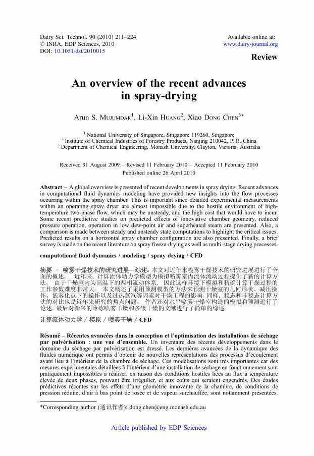
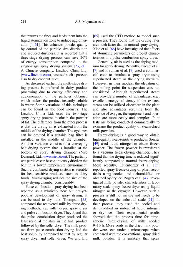
All thesemodels are a significant advancein modeling of spray drying because themass, momentum and energy equationsweresolved with no restrictive assumptions aboutthe drying chamber geometry and gas inletconditions. These advantages allow one toinvestigate the new designs of drying cham-ber and the effects of inlet geometry varia-tions on dryer performance. For example,Huang et al. [17] investigated severalnew chamber designs by CFD modelingapproach, i.e., conical, lantern and hour-glasschamber geometries, for spray drying. Theyfound that pure cone and lantern shapes canbe used as viable drying chamber designs,although they are not yet used in industry.Pilot testing may be desirable for such novelchamber geometries. More work is neededalong with the effect of supplemental inletgas streams to see their potential benefits.One-stage and two-stage HSDs were investi-gated using CFD approach as well [19, 20].The velocity magnitude contours are shownin Figure 1. It can be seen that there are somehigh velocity regions near each fluidized bedplate inlet. This blocks thedroplets thatmightdeposit at the bottom of the chamber in one-stageHSD. Also, the fluidized bed at the bot-tom of the chamber affects the chamber flowpattern as well, i.e., the high velocity regionat the main inlet is extended. In a real dryingcondition, this may enhance heat and masstransfer between the droplets and dryingmedium.
Xu et al. [67] have recently examinedparabolic-shaped chamber geometries for
216 A.S. Mujumdar et al.
hydro-cyclones, which also involve vortexflows similar to those in the conical sectionof a spray dryer. They reported significantlyreduced erosion rates for such geometry. Inspray drying, this may mean reduced walldeposits. It is an interesting but as-yetuntested design.
Methods for reducing deposition in spraydryers can be classified into two types: thoseinvolved in reducing particle-wall contactand those that reduce the stickiness of parti-cle-wall contact. Some recent work on thelatter aspect involves manipulating the wallsurface energy. This idea was proposed ina review by Bhandari and Howes [1] inwhich lower wall surface energy was found
to result in less stickiness of the amorphousparticle-wall contact. Although such aneffect was not observed in a particle gunexperiment [40], recent investigations onpilot-scale dryers revealed the potential ofusing wall material with lower surfaceenergy [64] and other non-sticky wall mate-rial [30] to combat the deposition problem.The reduction mechanism was further con-firmed with elevated wall temperatures, tomimic industrial operation, that lower sur-face energy reduces deposition of amor-phous particles [63]. In the latter report,within a limited operational window, lowersurface energy also improved the ease inremoving the deposited particles. From some
Figure 1. Velocity magnitude contours for one-stage and two-stage HSDs: (a) one-stage HSD and(b) two-stage HSD (the fluidized bed covers the entire bottom boundary of this device simulated).
An overview of the recent advances in spray-drying 217

preliminary results, itwas speculated that thismight reduce the cleaning effort required fora spray dryer [63].
In terms of modeling of wall depositsusing the CFD Lagrangian-Eulerianapproach, mixed results on the modeling ofdeposition can be found in the literature[16, 18, 31]. Of course, one should not attri-bute this solely to the deposition model, asthe airflowprediction also plays an importantpart in the accuracy of the models. MostCFD work utilizes the stick-upon-contactapproach [18].However, a particlemay exhi-bit different degree of stickiness and impact-ing velocity or angle, depending on itslocation or moisture content. These willfurther affect the rebound characteristics ofa particle. A first step in addressing the for-mer aspect was proposed by Harvie et al.[16] in utilizing the sticky point, which isrelated to the glass transition and is a functionof particle moisture and temperature, as adeposition criterion. While taking intoaccount the particle stickiness, this approachdoes not consider the effect of impactingvelocity and angle. Although the effect ofthese collision parameters is yet to bequantified in a spray dryer, it is known thatparticle restitution is sensitive to these param-eters and will be interesting to incorporatethese in future development of depositionmodels.
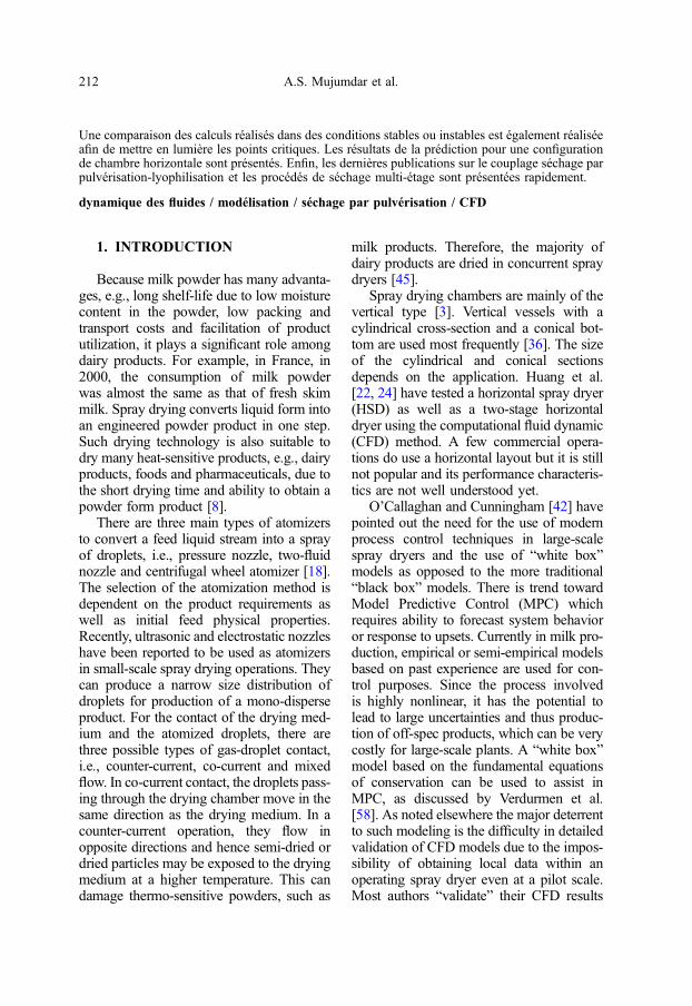
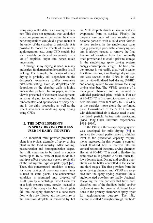
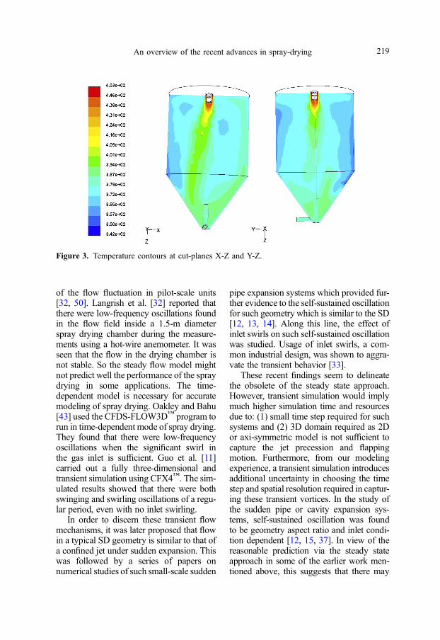
Huang andMujumdar [19] investigated aspray dryer fitted with a centrifugal atomizerusing CFDmodel. In their model, they mod-eled the rotary disk atomization into the diskside point injection which was the same asthe holes in the disk. The path-lines fromthe air inlet of drying chamber are shownin Figure 2. It was seen that there was strongswirling just below the atomizer disk due tothe disk rotation. This swirling significantlyaffected the flow pattern in the chamber.This was proved from the non-uniform tem-perature contours at planes X-Z and Y-Z,shown in Figure 3. It was also seen that therewas a low-temperature region away from thecentral line at plane X-Z. It indicated that
more droplets passed through this regiondue to the central swirling.
However, the works above all assumedsteady flow in spray drying. A recent reviewsuggests that the airflow pattern, specificallythe central jet, has tendency to exhibit self-sustained oscillatory behavior and this isimportant to be accounted for in a CFDmodel. There are significant differencesbetween the wall deposit rates and locationsfor steady and unsteady swirling flows. Ofcourse, experimental verification is yet tobe reported. While data on pilot size spraydryers are more realistically obtained formodel validation, significant uncertaintystill remains when the model is to beapplied to full-scale dryers.
Initial work on the transient behaviorinvolved visualization and measurement
Figure 2. Path-lines from the air inlet of dryingchamber.
218 A.S. Mujumdar et al.
of the flow fluctuation in pilot-scale units[32, 50]. Langrish et al. [32] reported thatthere were low-frequency oscillations foundin the flow field inside a 1.5-m diameterspray drying chamber during the measure-ments using a hot-wire anemometer. It wasseen that the flow in the drying chamber isnot stable. So the steady flow model mightnot predict well the performance of the spraydrying in some applications. The time-dependent model is necessary for accuratemodeling of spray drying. Oakley and Bahu[43] used the CFDS-FLOW3D™ program torun in time-dependent mode of spray drying.They found that there were low-frequencyoscillations when the significant swirl inthe gas inlet is sufficient. Guo et al. [11]carried out a fully three-dimensional andtransient simulation using CFX4™. The sim-ulated results showed that there were bothswinging and swirling oscillations of a regu-lar period, even with no inlet swirling.
In order to discern these transient flowmechanisms, it was later proposed that flowin a typical SD geometry is similar to that ofa confined jet under sudden expansion. Thiswas followed by a series of papers onnumerical studies of such small-scale sudden
pipe expansion systems which provided fur-ther evidence to the self-sustained oscillationfor such geometry which is similar to the SD[12, 13, 14]. Along this line, the effect ofinlet swirls on such self-sustained oscillationwas studied. Usage of inlet swirls, a com-mon industrial design, was shown to aggra-vate the transient behavior [33].
These recent findings seem to delineatethe obsolete of the steady state approach.However, transient simulation would implymuch higher simulation time and resourcesdue to: (1) small time step required for suchsystems and (2) 3D domain required as 2Dor axi-symmetric model is not sufficient tocapture the jet precession and flappingmotion. Furthermore, from our modelingexperience, a transient simulation introducesadditional uncertainty in choosing the timestep and spatial resolution required in captur-ing these transient vortices. In the study ofthe sudden pipe or cavity expansion sys-tems, self-sustained oscillation was foundto be geometry aspect ratio and inlet condi-tion dependent [12, 15, 37]. In view of thereasonable prediction via the steady stateapproach in some of the earlier work men-tioned above, this suggests that there may
Figure 3. Temperature contours at cut-planes X-Z and Y-Z.
An overview of the recent advances in spray-drying 219
be certain operating and geometry combina-tions in which the steady state will prove tobe a good approximation. Kota and Langrish[30], in their numerical study, noted that themild transient jet movement of a non-swirl-ing inlet flow only caused small fluctuationsin the overall particle deposition trend at dif-ferent transient simulation time.
Therefore, it will be interesting and prac-tical to determine the possibility of suchboundaries or “map” to discern the suitabilityof the steady state or transient approach inactual dryer geometries for effective applica-tion of the CFD tool. As would be noted,most of the studies on the transient behaviorweremainly focused on the non-swirling andinlet swirling flows, without much attention
being placed on the atomizer-inducedswirling flows. Some preliminary work iscurrently underway in these two areas men-tioned. Apart from that, Langrish et al. [33]also noted that airflow studies undertakenhitherto are mainly without inclusion of thedroplets or particles. It is unclear how thedroplet-air momentum transfer near the inletregion will affect the possible transientbehavior of the jet. Further work was sug-gested in this area [33].
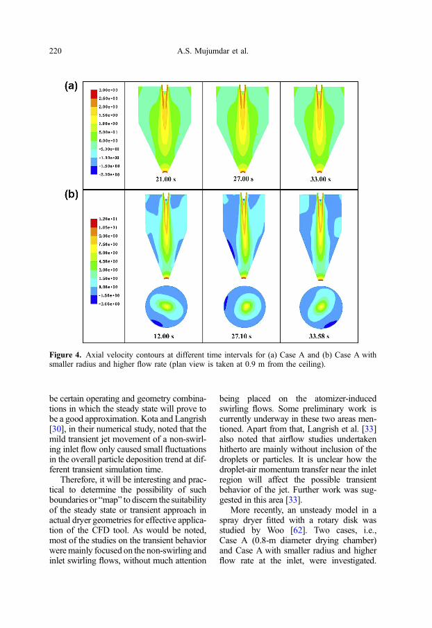
More recently, an unsteady model in aspray dryer fitted with a rotary disk wasstudied by Woo [62]. Two cases, i.e.,Case A (0.8-m diameter drying chamber)and Case A with smaller radius and higherflow rate at the inlet, were investigated.
Figure 4. Axial velocity contours at different time intervals for (a) Case A and (b) Case A withsmaller radius and higher flow rate (plan view is taken at 0.9 m from the ceiling).
220 A.S. Mujumdar et al.
Non-periodic and unstable fluctuation pat-terns were observed. These illustrate thedependence of the jet in an actual spraydryer on the radial expansion ratio and inletReynolds number which quantified thefeedback effect when the jet encounteredany obstruction in the confined geometryor due to the backflow hydrodynamics. Inthis case, it was the constriction at the outletand the recirculation region at the outerannular region of the chamber. On the effectof Reynolds number, Maurel et al. [37] haveshown, with their small-scale laboratoryexperiments, that the oscillation regimes ofnon-swirling confined jets under suddenexpansion are sensitive to this parameter.These findings also explained why fewworkers reported semi-symmetric andquasi-steady state solution in chambers oflarger diameter for non-rotating flows [56].
In Figure 4, axial velocity contours at dif-ferent time intervals for the two tested casesare shown.The contour plots at differentflowtimes for Case A are shown in Figure 4a.Contrary to the findings of Guo et al. [15]on different dryer geometries, it was foundthat there was no significant unsteadiness inthe simulation without atomizer rotation. Itcan be seen from Figure 4b that the tip ofthe jet stretched and expanded. This occurredin many directions in an unsteady manner,similar to the findings of Guo et al. [15].
However, lack of carefully obtainedexperimental data – primarily due to oftenthe proprietary nature of the process and dif-ficulty of making the necessary detailedmeasurements – is currently hampering thedevelopment of CFD-based design andanalysis of spray dryers. It is quite possiblethat the numerical predictions almost as reli-able as experimental data can be obtainedwithin the spray dryer chamber under oper-ating conditions. Mezhericher et al. [38, 39]explored droplet interactions in a pilot-scaledryer numerically and further examined theeffects of 2D or 3D modeling approaches.Most recently, Jin and Chen [25, 26, 27]have conducted transient CFD modeling
of large-scale industrial spray drying pro-cesses including an investigation on powderdeposition in a large-scale dryer [27] thathas 9 tonnes powder production perhour [5]. There are still some limitationsto depending entirely on the CFD approachsince it does not typically include reliablemodels based on experience for qualitychanges, attrition or agglomeration of parti-cles that can occur within the chamber.
4. CONCLUSION
Spray drying is an important step indairy powder processing. Of course, it is atechnology that has a very wide range ofapplications and in this review greater atten-tion has been paid to those applied in thedairy industry. Dried dairy products havelong shelf-life and are easy to be used atremote locations from the production areaor country hence having a great influenceon international trade. Three-stage dryingsystem is commonly used, which includesprimary drying (spray drying) and fluidizedbed drying (second and third stages). Thissystem is by far the most efficient approach.Recently, some new drying technologies,e.g., spray freeze-drying and superheatedsteam spray drying, are also developed.These new drying technologies are stillexploratory and due to the potentiallyhigher costs, they are considered for somespecial products that are heat-sensitive andpricy.
It is noteworthy that with CFD technol-ogy developing rapidly, mathematical mod-eling has become a useful tool to simulatethe complex drying process and guidefuture developments without excessiveexperimental trial-and-error associatedcosts. However, measurements at an indus-trial scale to validate the computer modelsare hard to come by. There are few experi-mental data at a large industrial scale (suchas several T of powder produced per hour).This does hamper the industrial confidence
An overview of the recent advances in spray-drying 221
upon the use of CFD software. Efforts arebeing placed to fill such a gap in bothacademia and industry, in particular, thosewho do work together coherently.
REFERENCES
[1] Bhandari B., Howes T., Relating the stick-iness property of foods undergoing dryingand dried products to their surface energetic,Drying Technol. 23 (2005) 791–797.
[2] Blei S., Sommerfeld M., Computation ofagglomeration for non-uniform dispersedphase properties – an extended stochasticcollision model, in: Proceedings of the5th International Conference on MultiphaseFlow, 30 May–4 June 2004, ICMF’04,Yokohama, Japan.
[3] Caric M., Concentrated and Dried DairyProducts, VCH Publishers, New York, USA,1994.
[4] Chen X.D., Whole milk powder agglomer-ation – principle and practice, in: Chen X.D.(Ed.), Milk Powders for the Future,Dunmore Press, Palmerston North,New Zealand, 1992.
[5] Chen X.D., Lake R., Jebson S., Study ofmilk powder deposition on a large industrialdryer, Trans. IChemE: Bio-Process. FoodProcess. 71 (1993) 180–186.
[6] Crowe C.T., Sharma M.P., Stock D.E., Theparticle-source-in-cell (PSI-Cell) model forgas-droplet flows, J. Fluid Eng. 9 (1977)325–332.
[7] Ducept F., Sionneau M., Vasseur J., Super-heated steam dryer: simulations and exper-iments on product drying, Chem. Eng. J. 86(2002) 75–83.
[8] Filkova I., Huang L.X., Mujumdar A.S.,Industrial spray drying systems, in:Mujumdar A.S. (Ed.), Handbook of IndustrialDrying, Taylor & Francis, New York, USA,2007, pp. 215–257.
[9] FrydmanA., Vasseur J., Ducept F.,Moureh J.,Simulation of spray drying in superheatedsteam using computational fluid dynamics,Drying Technol. 17 (1999) 1313–1326.
[10] Goldberg J.E., Prediction of Spray DryerPerformance, Ph.D. Thesis, University ofOxford, UK, 1987.
[11] Guo B., Langrish T.A.G., Fletcher D.F.,Time-dependent simulation of turbulentflows in axisymmetric sudden expansions,
in: Thompson M.C., Hourigan K. (Eds.),Proceedings 13th Australasian FluidMechanics Conference, Melbourne,Australia, 1998, pp. 283–286.
[12] Guo B., Langrish T.A.G., Fletcher D.F.,Numerical simulation of unsteady turbulentflow in axisymmetric sudden expansions,J. Fluids Eng. 123 (2001) 574–587.
[13] Guo B., Langrish T.A.G., Fletcher D.F.,Simulation of turbulent swirl flow in anaxisymetric sudden expansion, AIAA J. 39(2001) 96–102.
[14] Guo B., Langrish T.A.G., Fletcher D.F.,CFD simulation of precession in sudden pipeexpansion flows with low inlet swirl, Appl.Math. Model. 26 (2002) 1–15.
[15] Guo B., Langrish T.A.G., Fletcher D.F.,Simulation of gas flow instability in a spraydryer, Chem. Eng. Res. Des. 81 (2003)631–638.
[16] Harvie D.J.E., Langrish T.A.G.,Fletcher D.F., A computational fluid dynam-ics study of a tall-form spray dryer, Trans.IChemE 80 (2002) 163–175.
[17] Huang L.X., Kumar K., Mujumdar A.S., Useof computational fluid dynamics to evaluatealternative spray dryer chamber configura-tions, Drying Technol. 21 (2003) 385–412.
[18] Huang L.X., Mujumdar A.S., Spray drying:principle and practice, in: Mujumdar A.S.(Ed.), Guide to Industrial Drying, 2ndenhanced edn., Colour Publications Pvt.Ltd., Mumbai, India, 2004, pp. 143–169.
[19] Huang L.X., Mujumdar A.S., Developmentof a new innovative conceptual design forhorizontal spray dryer via mathematical mod-eling, Drying Technol. 23 (2005) 1169–1187.
[20] Huang L.X., Mujumdar A.S., Numericalstudy of two-stage horizontal spray dryersusing computational fluid dynamics, DryingTechnol. 24 (2006) 727–733.
[21] Huang L.X., Mujumdar A.S., Simulation ofan industrial spray dryer and prediction ofoff-design performance, Drying Technol. 25(2007) 703–714.
[22] Huang L.X., Passos M.L., Kumar K.,Mujumdar A.S., A three-dimensional simu-lation of a spray dryer fitted with a rotaryatomizer, Drying Technol. 23 (2005)1859–1873.
[23] Huang L.X., Wang Z., Tang J., Recentprogress of spray drying in China [inChinese], Chem. Eng. (China) 29 (2001)51–55.
222 A.S. Mujumdar et al.
[24] Huang L.X., Zheng W.H., Wang C.Z.,Mujumdar A.S., Leuenberger H., Sprayfreeze drying and its applications in dryingof plant extracts and pharmaceuticals [inChinese], Chem. Ind. For. Prod. 27 (2007)143–146.
[25] Jin Y., Chen X.D., A three-dimensionalnumerical study of the gas/particle interac-tions in an industrial-scale spray dryer formilk powder production, Drying Technol. 27(2009) 1018–1027.
[26] Jin Y., Chen X.D., Numerical study of thedrying process of different sized particles inan industrial-scale spray dryer, Drying Tech-nol. 27 (2009) 371–381.
[27] Jin Y., Chen X.D., A numerical model forthe particle deposition on industrial milkdryers, Drying Technol. (to appear).
[28] Katta S., Gauvin W.H., Some fundamentalaspects of spray drying, AIChE J. 21 (1975)143–150.
[29] Kieviet F.G., Modelling Quality in SprayDrying, Ph.D. Thesis, Endinhoven Univer-sity of Technology, The Netherlands, 1997.
[30] Kota K., Langrish T.A.G., Fluxes and pat-terns of wall deposits for skim milk in apilot-scale spray dryer, Drying Technol. 24(2006) 993–1001.
[31] Kota K., Langrish T.A.G., Prediction ofdeposition patterns in a pilot-scale spraydryer using computational fluid dynamics(CFD) simulations, Chem. Prod. ProcessModel. 2 (2007) Article 26.
[32] Langrish T.A.G., Oakley D.E., Keey R.B.,Bahu R.E., Hutchinson C.A., Time-depen-dent flow patterns in spray dryers, Trans.IChemE 71 (1993) 355–360.
[33] Langrish T.A.G., Williams J., Fletcher D.F.,Simulation of the effects of inlet swirl on gasflow patterns in a pilot-scale spray dryer,Chem. Eng. Res. Des. 82 (2004) 821–833.
[34] Langrish T.A.G., Zbicinski I., The effects ofair inlet geometry and spray angle on thewall deposition rate in spray dryers, Trans.IChemE 72 (1994) 420–430.
[35] Leuenberger H., Plitzko M., Puchkov M.,Spray freeze drying in a fluidized bed atnormal and low pressure, Drying Technol.24 (2006) 711–719.
[36] Masters K., Spray Drying Handbook,5th edn., John Wiley & Sons Inc.,New York, USA, 1991, pp. 725–726.
[37] Maurel A., Ern P., Zielinska B.J.A.,Wesfreid J.E., Experimental study of
self-sustained oscillations in a confined jet,Phys. Rev. E 54 (1996) 3643–3651.
[38] Mezhericher M., Levy A., Borde I., Droplet-droplet interactions in spray drying by using2D Computational Fluid Dynamics, DryingTechnol. 26 (2008) 265–282.
[39] Mezhericher M., Levy A., Borde I., Model-ing of droplet drying in spray chambers using2D and 3D computational fluid dynamics,Drying Technol. 27 (2009) 359–370.
[40] Murthi R.A., Paterson A.H.J., Pearce D.,Bronlund J.E., Controlling SMP stickinessby changing the wall material: feasible ornot?, in: Proceedings of Chemeca, Auckland,New Zealand, 2006, CD-ROM, paper 209.
[41] Nhumaio G.C.S., Watkins A.P., Yule A.J.,Experiments and CFD predictions of twooverlapping water sprays issued from air-assist atomizers, in: Proceedings ILASSEurope 19th Annual Conference on LiquidAtomization and Spray Systems, 6–8September 2004, Nottingham, UK, 2004.
[42] O’Callaghan J., Cunningham P., Modernprocess control techniques in the productionof dried milk – a review, Lait 85 (2005)335–342.
[43] Oakley D.E., Bahu R.E., Spray/gas mixingbehavior within spray dryers, in: MujumdarA.S., Filkova I. (Eds.), Drying’91, Elsevier,Amsterdam, The Netherlands, 1991.
[44] Parti M., Palancz B., Mathematical modelfor spray drying, Chem. Eng. Sci. 29 (1974)355–362.
[45] Passos M.L., Mujumdar A.S., Mathematicalmodels for improving spray drying processesfor foods, Stewart Post-harvest Review,www.stewartpostharvest.com, 2005.
[46] Pisecky J., Evaporation and spray drying inthe dairy industry, in: Mujumdar A.S. (Ed.),Handbook of Industrial Drying, Vol. 1,2nd edn., Marcel Dekker Inc., New York,USA, 1995, pp. 715–742.
[47] Rogers S., Wu D., Saunders J., Chen X.D.,Characteristics of milk powders produced byspray freeze drying, Drying Technol. 26(2008) 404–412.
[48] Sommerfeld M., Validation of a stochasticLagrangian modeling approach for inter-particle collisions in homogeneous isotropicturbulence, Int. J. Multiphase Flow 27(2001) 1829–1858.
[49] Sonner C., Protein-Loaded Powders bySpray Freeze Drying, Ph.D. Thesis,
An overview of the recent advances in spray-drying 223
Department of Pharmaceutics, Friedrich-Alexandar University, Erlangen, Germany,2002.
[50] Southwell D.B., Langrish T.A.G., Observa-tions of flow patterns in a spray dryer,Drying Technol. 18 (2000) 661–685.
[51] Straatsma J., van Houwelingen G.,Meulman A.P., Steenbergen A.E., Dry-SPEC2: a computer model of a two-stagedryer, J. Soc. Dairy Technol. 44 (1991)107–111.
[52] Straatsma J., van Houwelingen G.,Steenbergen A.E., De Jong P., Spray dryingof food products: 1. Simulation model,J. Food Eng. 42 (1999) 67–72.
[53] Straatsma J., van Houwelingen G.,Steenbergen A.E., De Jong P., Spray dryingof food products: 2. Prediction of insolubil-ity, J. Food Eng. 42 (1999) 73–77.
[54] Tang J.X., Huang L.X., Wang Z.L., Three-stage drying system and its application indairy product processing [in Chinese],J. Nanjing Forestry 21 (1997) 56–58.
[55] Thompson R.I., Nutrient Profile, FunctionalProperties and Microstructure of DriedWaste Milk Product for Use as a PotentialAnimal Feed, Ph.D. Thesis, Louisiana StateUniversity, USA, 2002.
[56] Ullum T., Simulation of a spray dryer withrotary atomizer: the appearance of vortexbreakdown, in: Proceedings of the 15th Inter-national Drying Symposium, 20–23 August2006, Budapest, Hungary, pp. 251–257.
[57] Verdurmen R.E.M., Menn P., Ritzert J.,Blei S., Nhumaio G.C.S., Sonne SørensenT., GunsingM., Straatsma J., VerschuerenM.,Sibeijn M., Schulte G., Fritsching U.,Bauckhage K., Tropea C., Sommerfeld M.,Watkins A.P., Yule A.J., Schønfeldt H.,Simulation of agglomeration in spray dryinginstallations: the EDECAD project, DryingTechnol. 22 (2004) 1403–1462.
[58] Verdurmen R.E.M., Straatsma H.,Verschueren M., van Haren J.J., Smit E.,Bargeman G., De Jong P., Modeling spraydrying processes for dairy products, Lait 82(2002) 453–463.
[59] Verdurmen R.E.M., Verschueren M.,Gunsing M., Straatsma H., Simulation ofagglomeration in spray dryers: the EDECADproject, Lait 85 (2005) 343–351.
[60] Westergaard V., Milk powder technology:evaporation and spray drying, Niro A/S,Søborg, Denmark, 1994, pp. 18–121.
[61] Williams A.M., Jones J.R., Paterson A.H.J.,Pearce D.L., Effect of fines on agglomera-tion in spray dryers: an experimental study,Int. J. Food Eng. (2009) DOI: 10.2202/1556-3758.1635.
[62] Woo M.W., The simulation of spray dryingunder unsteady flow using CFD, 2008,private communications.
[63] Woo M.W., Daud W.R.W., Tasirin S.M.,Talib M.Z.M., Controlling food powderdeposition in spray dryers: wall surfaceenergy manipulation as an alternative,J. Food Eng. 94 (2008) 192–198.
[64] Woo M.W., Daud W.R.W., Tasirin S.M.,Talib M.Z.M., Effect of wall surface prop-erties at different drying kinetics on thedeposition problem in spray drying, DryingTechnol. 26 (2008) 15–26.
[65] Wu Z.H., Liu X.D., Simulation of spraydrying of a solution atomized in a pulsatingflow, Drying Technol. 20 (2002) 1101–1121.
[66] Xiao Z.F., Xie X.Y., Yuan Y.J., Liu X.D.,Influence of atomizing parameters on dropletproperties in a pulse combustion spray dryer,Drying Technol. 26 (2008) 427–432.
[67] Xu P., Ray M.B., Mujumdar A.S., Yu B.,Design and optimize hydrocyclones withCFD model, in: Proceedings of 8th WorldCongress of Chemical Engineering, 23–27August 2009, Montreal, Canada (to appear).
224 A.S. Mujumdar et al.