Embed Size (px)
Citation preview

An Overview of Polarimetric Sensing Techniques andTechnology with Applications to Different Research Fields
Frans Snika, Julia Craven-Jonesb, Michael Escutic, Silvano Fineschid, David Harringtone,Antonello de Martinof, Dimitri Mawetg, Jerome Riedih, J. Scott Tyoi
aSterrewacht Leiden, Universiteit Leiden, Niels Bohrweg 2, 2333 CA, Leiden, the Netherlands;bSandia National Laboratories, PO Box 5800-0406, Albuquerque, NM 87185-0406, USA;
cNorth Carolina State University, 432 Monteith, Campus Box 7914, Raleigh, NC 27695-7914, USA;dINAF - Osservatorio Astrofisico di Torino, Strada Osservatorio 20, 10025 Pino Torinese (TO), Italy;eUniversity of Hawaii, Institute for Astronomy, 2680 Woodlawn Drive, Honolulu, HI 96822-1839, USA;
fEcole Polytechnique - PICM, Route de Saclay, 91128 Palaiseau, France;gEuropean Southern Observatory, Alonso de Cordova 3107, Vitacura, 763 0355, Santiago, Chile;
hLaboratoire d’Optique Atmospherique, Universite Lille1, Cite Scientifique, 59655 - Villeneuve d’Ascq Cedex, France;iCollege of Optical Sciences, Univ. of Arizona, 1630 E. University Blvd., PO Box 210094, Tucson, AZ 85721-0094, USA.
ABSTRACT
We report the main conclusions from an interactive, multidisciplinary workshop on “Polarimetric Techniquesand Technology”, held on March 24-28 2014 at the Lorentz Center in Leiden, the Netherlands. The work-shop brought together polarimetrists from different research fields. Participants had backgrounds ranging fromacademia to industrial R&D. Here we provide an overview of polarimetric instrumentation in the optical regimegeared towards a wide range of applications: atmospheric remote sensing, target detection, astronomy, biomed-ical applications, etc. We identify common approaches and challenges. We list novel polarimetric techniquesand polarization technologies that enable promising new solutions. We conclude with recommendations to thepolarimetric community at large on joint efforts for exchanging expertise.
Keywords: polarimetry
1. INTRODUCTION
Polarization is a fundamental property of light, and light from any source is polarized to some degree. Po-larimetry is therefore a valuable technique to remotely obtain information about a wide range of sources andobjects. It is therefore implemented in many different research fields, in many different ways. This paper reviewsthose implementations of polarimetry and their applications. Furthermore, we identify common challenges forpolarimetric applications, and we list new developments and novel techniques that are of general benefit. Aspolarimetry is still evolving as a general-purpose technique, and often considered specialistic and difficult, weaim to provide an overview to the non-specialist reader. We refer to recent books, review papers and landmarkpublications wherever possible.
This publication is one of the results from an interactive workshop on “Polarimetric Techniques & Technol-ogy”, organized at the Lorentz Center∗ in Leiden, the Netherlands. This workshop was co-organized by the EUCOST network “Polarisation as a tool to study the solar system and beyond”†. The authors of this paper actedas the Scientific Organizing Committee. This workshop brought together polarimetrists from a wide range ofscientific backgrounds (atmospheric remote sensing, target detection, astronomy, biomedical applications, etc.),as well as representatives from industry. The first two days of the workshop consisted of contributed talks toinform the audience about the state-of-the-art and challenges of polarimetric applications, whereas the remain-ing three days were dedicated to plenary and splinter discussion sessions and interactive design challenges. Thispaper reports on the most notable outcomes of these talks, discussions and assignments.
email: [email protected]∗www.lorentzcenter.nl†www.polarisation.eu

2. CONVENTIONS
All fields of optical (i.e. the UV-IR range) polarimetry adopt the Stokes formalism to describe the polarizationmeasurement, as the detectors are only sensitive to the total intensity (photon count) and not to phase andamplitude of the incident light, or the orientation of the electric field. Moreover, the Stokes formalism is ideallysuited for the description of partially polarized light, and light in nature is almost never fully polarized. Theoperational definition of the Stokes vector conveniently describe the polarized Stokes parameters as differencesof intensity measurements. The second and third Stokes parameters fully describe the linear polarization stateof light, and the fourth one describes circular polarization. In many cases, it is preferable to describe themeasurement results in terms of fractional polarization (by dividing the polarized Stokes parameters by theintensity), or in terms of degree of (linear/circular) polarization and angle of (linear) polarization.
While the same mathematic language is spoken in the separate communities, several dialects are prevalent. Forinstance, the remote sensing / target detection community denotes the Stokes parameters with [S0, S1, S2, S3]T ,1
whereas the astronomical / atmospheric community uses [I,Q, U, V ]T .2 While the first convention is convenientfor index arithmetic in vector/matrix calculus, it can also be confusing as in many fields of optics Si is adopted,e.g., to list measured signals. The use of [I, Q, U, V ]T has a historical origin, as this is the notation thatChandrasekhar used when he reintroduced the work of Stokes in 1947.
In the different fields, many sign conventions are in use for the coordinate system of [S1, S2],[Q, U ] and forthe handedness of S3,V , and in many cases these conventions are not even observed. For instance, the definitionsof the IEEE and the International Astronomical Union3 are opposite to those that emerge from a basis of Paulispin matrices.4 It is probably impossible to agree on a single convention, but it is apropos to emphasize herethat authors should state their coordinate system for the Stokes parameters. In the end, it might only comedown to a minus sign flip for S2,U and/or S3,V , but this may still be crucial for the interpretation of the results.
Coherence effects cannot be described by the Stokes formalism, and are generally ignored. Nevertheless, insome cases interference effects are significant, and other formalisms need to be used: the Jones formalism, theWolf coherence matrix formalism,5 and Berreman calculus6 (for thin-film interference effects). When using theStokes formalism in scattering application with coherent illumination, i.e. in laser Mueller matrix polarimetry,care must be taken to properly account for the coherent effects of speckles in analyzing the data.7
Many different terms are in use to describe the quality of a polarimetric measurements: polarimetric “error”,“noise”, “sensitivity”, “precision”, “accuracy”, “uncertainty”, etc. The most well-defined terms are probably the“polarimetric sensitivity”, which describes the noise level in fractional polarization above which a polarizationsignal can be detected, and the “polarimetric accuracy” that relates the measured Stokes parameters (aftercalibration) to the true ones.2,4 The latter should then be expressed as a 4×4 matrix in the case of a full-Stokesmeasurement, but it can often be compressed into a requirement for the polarization zero-point, the scale, andthe cross-talk between linear and circular polarization.
3. POLARIMETRIC APPLICATIONS
3.1 Atmospheric Remote SensingPolarimetry is considered a crucial technique in atmospheric remote sensing, and, in particular, for character-ization of aerosol particles. In fact, only the combination of polarization measurements of scattered sunlightwith multi-spectral and multi-angle functionality allows for the unambiguous, remote retrieval of several aerosolproperties: the aerosol optical thickness, and microphysical properties like the size distribution, the chemicalcomposition (through the complex refractive index) and the particle shape (spherical, non-spherical, jagged, etc.).Such measurements are not only required to assess the health hazards of aerosols and to probe volcanic ash cloudsthat impact air traffic, they are also crucial to measure aerosol scattering/absorption properties that currentlyconstitute the largest source of uncertainty within climate modeling. In addition to dedicated ground-basedpolarimetric instrumentation,9 there are several satellite instruments under development to provide polarimetricaerosol measurements on a global scale. We review these instruments, as they are also exemplary for the widerange of design options for polarimetric instrumentation.
The POLDER instrument10 has flown in three different incarnations and has pioneered space-based polari-metric remote sensing. Its design is also the blueprint for future, more powerful instruments, like 3MI onboard

Intensity Polarization
Figure 1. a) POLDER data: true-color intensity and corresponding polarized intensity at 440, 670, 865 nm, exhibitingscattering properties of the atmosphere and cloudbow features that are used to retrieve droplet size (courtesy: JeromeRiedi). b) MSPI data from PODEX8 campaign, flying over Bakersfield, CA. Crop fields are clearly discerned, as arewastewater treatment ponds (courtesy: David J. Diner and the AirMSPI Team/Jet Propulsion Laboratory).
EPS-SG (EUMETSAT Polar System - Second Generation). POLDER is a fisheye imager that employs a filterwheel for its multi-spectral and also its multi-polarization capabilities. Several of the wavelength filters (433,670, 865 nm) are repeated three times and paired with linear polarizers at 0, 60 and 120 degrees, such that the

linear Stokes parameters can be measured for each of the filter bands after three positions of the filter wheel. Asthis filter wheel rotates while the satellite is flying over ground scenes, the three recordings differ slightly. Aftercareful calibration (also of the instrumental polarization due to the fisheye optical system), the polarimetricaccuracy for POLDER measurements is ∼2% for scenes with large spatial gradients. A sample of POLDER datais presented in Fig. 1a.
To provide more information about the chemical composition of aerosol particles, a polarimetric accuracy of∼ 10−3 is required. Three, very different, polarimetric instrument concepts are being developed to provide suchhigh-accuracy polarimetry. The Research Scanning Polarimeter11 and the Aerosol Polarimetry Sensor12 weredesigned to deliver strictly simultaneous linear polarization measurements. Unfortunately, the GLORY satellitethat carried the APS instrument failed to achieve orbit in 2011. The polarimetry is implemented throughseveral boresighted telescopes with dichroic beam-splitter and Wollaston prisms under 0/90◦ and ±45◦ that feedmultiple photodiodes. The ground scene is rapidly scanned by a rotating assembly of two crossed mirrors, suchthat their combined instrumental polarization properties are minimized. This mechanism can also be pointedto feed light through a polarization calibration unit that verifies the polarization accuracy of ∼0.2% that wasachieved on-ground.
The Multi-angle SpectroPolarimeter Imager (MSPI13) contains a three-mirror anastigmat telescope thatimages a strip of ±15 degrees along the flight direction onto 13 line detector strips that cover various wavelengthbands. Observations under various angles along track are effectuated by sweeping a single instrument or byeither employing a multitude of identical subsystems under different angles or scanning a single system back andforth. The polarization modulator is a dual photo-elastic modulator (PEM) system in between two athermalquarter-wave plates that are optimized for performance in the three polarimetric bands (470, 660, 865 nm). Thebeat frequency of the two PEMs at 12.5 Hz produces a modulation signal for the detector which is rapid enoughto suppress polarization artifacts due to motion smearing down to the ∼0.5% level. The detector strips forthe polarimetric wavelength bands are covered by wire-grid polarizers at 0 and 45 degrees, such that the linearStokes parameters are measured simultaneously. The modulator package is located after the first two telescopemirrors, which are covered with low-polarization (<1%) coatings. A sample image from the AirMSPI instrumentis presented in Fig. 1b.
The SPEX concept14 is based on spectral polarization modulation (see subsection 4.1): a modulator packageimplemented for each viewing direction produces a sinusoidal modulation onto the spectrum for which theamplitude scales with the degree of linear polarization, and the phase is determined by the angle of linearpolarization. The major advantage of this polarimetric technique is that all information on both spectrumand polarization is contained in a single shot, which renders it impervious to differential effects that oftenplague temporal or spatial modulation polarimeters. A polarimetric accuracy of 0.2% has been shown in thelab. Moreover, the spectral modulator can be located all the way upstream in the optical train, such thatthe instrumental polarization is minimal. The SPEX instrument employs a spectrometer that combines the(spectrally modulated) light from various viewing directions with extended swath onto a single slit. By locatinga Wollaston prism in front of the objective lens for each viewing direction, two split spectra are imaged ontothe slit, which contain opposite spectral polarization modulations, such that the sum of the two beams (aftercorrection of transmission differences) yields the unmodulated intensity spectrum at full spectral resolution.
3.2 Target Detection
In target detection applications (e.g. machine vision, military application) polarimetry is often applied as acontrast-enhancing technique. Whereas spectral characteristics like color or thermal emission depend on thematerials that make up the objects in a scene, the polarization properties depend strongly on the surface shape,orientation and roughness. The result is that spectral and polarization information often provide independentfeatures for detection of an object that has similar spectral characteristics as the background or is hidden in acluttered environment. The cause for this is that either polarization is created by reflection of (sun)light upon adielectric or metallic surface or by refraction of thermal emission at such a surface, or that light is depolarizedby the target in a different way than its surrounding objects. Imaging polarimeters for target detection needto be fast and deliver real-time data. The polarimetric configurations are therefore often as simple as possible,involving beam-splitting systems (“division of amplitude” or “division of aperture”1) or micropolarizer arrays on

top of the focal-plane array (“division of focal plane”). See section 4 for an in-depth discussion of polarization-measurement techniques. Fig. 2a contains an example of a system with two synchronized thermal IR camerasbehind a regular polarizing beam-splitter that can therefore provide the first two Stokes parameters in real time.Fig. 2b presents a result from a micropolarizer system, which also provides real-time results.
Intensity Polarization
Figure 2. a) Tank in thermal equilibrium, imaged with an infrared camera in intensity and degree of linear polarization(courtesy: David Cenault, Polaris). b) Cars imaged with a microgrid polarizer focal-plane array. In degree of linearpolarization only the windscreens stand out (courtesy: Dmitry Vorobiev).
3.3 Astronomy
In astronomy, the goal for polarimetric instrumentation2,3, 15,16 is often required to detect tiny polarizationsignals (∼1% down to 10−6). We distinguish imaging polarimetry that is often used to reveal circumstellarstructures (see Fig. 3a) and is being employed to directly image exoplanets, and spectropolarimetry that canprobe the physical environment of stars and other astronomical objects through line polarization. For instance,a magnetic field splits up spectral lines according to the Zeeman effect. The split line components are alldifferently polarized,2 and hence sensitive polarimetry can probe 3D magnetic structure, even if the magneticfield is so small that the spectral line splitting is not measurable in intensity. The largest polarization effect isin circular polarization for a magnetic field component along the line-of-sight, and this effect has been used formore than a hundred years now (since G. E. Hale in 1908) and is now routinely employed at ground-based andsatellite solar telescopes to monitor solar activity (see Fig. 3b). The same techniques are now used to measureand map (!) magnetic fields on unresolved stars, by employing also the Doppler effect and rotation-phase-resolvedhighly sensitive spectropolarimetry. In general, the light from astronomical targets is polarized whenever somedeparture from spherical symmetry is present, which is even the case for stars. Therefore, polarimetry enables

Intensity Polarization
Figure 3. a) ExPo17 observations of the young star T Tauri. Sensitive imaging polarimetry reveals the structure of thecircumstellar disk, as its material scatters the light from the central star (courtesy: Michiel Rodenhuis). b) Solar full-diskimages from the SDO-HMI satellite instrument. Polarimetric measurements in a Zeeman-sensitive spectral line reveal thecomplex and dynamic solar magnetic field structure (from http://sdo.gsfc.nasa.gov/data/).
probing of spatial structures that are way beyond the capabilities of adaptive optics at large telescopes andlong-baseline interferometry.
To reach high polarimetric sensitivity, several systematic effects need to be overcome. First and foremost,atmospheric turbulence creates “seeing” (i.e. twinkling of stars), which limits polarimetry if consecutive imagesare combined to form a polarization measurements. Simultaneous measurements after a polarizing beam-splittersuffer from differential effects that limit the polarimetric sensitivity to ∼10−3. Therefore, many astronomical

polarimeters combine polarization measurement techniques to cancel out systematic effects (the so-called “dual-beam approach”, see subsection 4.3). Another solution is to implement temporal polarization modulation thatis faster than the seeing (∼1 kHz), and measure the polarization information at the focal plane with a singleset of pixels. As large-format, low-noise imaging detectors can generally not be read out at kHz rates, specialdemodulating detectors have been developed18,19 that combine a CCD with a stripe-mask and charge-shufflingthat is synchronized with the fast polarization modulation. The polarization measurement is then built up in two(or more) interlaced detector images, that are read out after many thousands of polarization modulation cycles.Through such methods (or combinations thereof), polarimetric sensitivities are achieved that are only limited byphoton noise. In that case, only the collection of more photons can improve upon the polarimetric sensitivity.Hence, large telescopes are necessary to collect these photons (even for solar observations!), but the photon noisecan also be pushed down by binning multiple observations, binning pixels, or combining many spectral lines withsimilar polarization signals.20
Modern telescopes generally also limit the polarimetric performance, as polarimetric instrumentation is oftenlocated behind several telescope mirrors, that both induce polarization that is often larger than the target polar-ization, and modify incoming polarization (“cross-talk”). These instrumental polarization effects are frequentlyvariable as they change with telescope pointing,21 and with aging and pollution of the mirrors. To fulfill de-manding requirements upon the polarimetric accuracy, elaborate polarization strategies have to be devised (seesubsection 4.5).
One of the most exciting challenges for astronomical polarimetry is to furnish direct observations of rockyexoplanets in the habitable zone. The contrast between such planets and their host stars is ∼10−7–10−10, and,as the reflected light off the planet is polarized whereas the starlight can be considered unpolarized, sensitivepolarimetry can be used to bridge that contrast, when coupled with extreme adaptive optics at extremelylarge telescopes and advanced coronagraphic techniques. Once such planets are detected in polarized light, thepolarization signal as a function of wavelength and as a function of the planetary phase angle (i.e. the orbitalmotion of the planet) can yield signatures of habitability like liquid water oceans and clouds, and biosignatures asatmospheric oxygen. For such exoplanet characterization, also high polarimetric accuracy is required. Also theultimate biosignature could be provided by polarimetry, as all complex molecules that are involved in biologicalprocesses (like amino acids, sugars, DNA and chlorophyll) are subject to homochirality: evolutionary processeshave made that only one handedness in the chemical structure prevails. This symmetry breaking leaves animprint upon circular polarization,22 although these signatures are yet at least an order of magnitude smallerthan the linear polarization signatures from a planetary atmosphere and surface. The exciting science goal offinding extraterrestrial life therefore poses tremendous challenges to future polarimetric instrumentation.
3.4 Biomedical Diagnostics
Polarimetric instrumentation for biomedical diagnostics23–25 has additional design freedom, as also the polariza-tion of the light source can be manipulated. In some cases, the light source is linearly polarized, and the scatteredlight from, e.g., tissue is analyzed in perpendicular and crossed polarization.25 Superficial, single-scattered lightemerges mostly with the same polarization as the input, whereas deep multiple-scattered light also has a perpen-dicularly polarized component. The purely superficial tissue structure is the easily obtained from a polarimetricdifference measurement. The degree of polarization associated with this measurement is a diagnostic for tissueproperties, and can be used for early cancer detection, see Fig. 4a.
Such a set-up is generalized by implementing a Polarization State Generator (PSG) in the input beam thatcan generate several or all (fully polarized) Stokes parameters. The polarimeter in the output beam is then calleda Polarization State Analyzer (PSA), and the overall instrument can be used to measure (part of) the Muellermatrix of tissue or a biological sample. This Mueller matrix can the be interpreted in terms of depolarization,retardance (amount and orientation) and polarizance.28 In turn, these parameters can be interpreted in terms oftissue properties. Depolarization can be caused by multiple scattering at isotropic structure, or by multidomainbirefringent structures. Oriented fiber structures (e.g. collagen and neural axons) can generally be modeled asoriented retarders (and/or partial polarizers). An example of such Mueller matrix diagnostics is presented inFig. 4b, for which the differences in depolarization indicate cancerous tissue.

Intensity Polarization
Figure 4. a) A mole (compound nevus) imaged through a polarizer parallel to the light source polarization, and in degreeof linear polarization, which enables diagnostics of the risk of melanoma (courtesy: Steven Jacques). b) Intensity imageand depolarized derived form Mueller matrix polarimetry of cancerous uterine cervix. The cuts indicate the results frompathology, which are instantaneously confirmed by the polarimetric imaging (adapted from Ref26). c) 3D mapping of fibertracts in the brain enabled by polarization microscopy of brain slices: intensity image and reconstructed fiber geometry(adapted from Ref27).

For similar measurements of internal organs, the input and output needs to occur through optical fibers.23
Generally, high-quality fibers do not depolarize or induce polarization, but they do act as retarders, and theirretardance properties change with the movement of the fiber. If the PSG and/or PSA are located on the externalend of the endoscope, these effects need to be monitored, calibrated and/or compensated for in quasi-real time.29
In the case of a depolarization measurement, these effects can be considered inconsequential by measuring thebreaking of orthogonality of polarization states.30 It remains a technical challenge to design a polarimetricimplementation at the internal fiber end.
Another application of biomedical polarimetry is microscopy of samples. Beautiful movies of cellular dynamicscan be made by enhancing the contrast in a polarizing microsope, see www.openpolscope.org. Also slices ofbrain tissue can be fully characterized using a polarimetric approach. The retardance measurement allows for a3D mapping of neural fiber structure, see Fig. 4c.
3.5 Other Applications
Polarimetry can be used to one’s advantage in many different areas of application. Here we provide a non-exhaustive list:
• ophtalmology, glaucoma detection
• surveillance
• crop monitoring
• dehazing
• ocean monitoring
• underwater vision
• landmine detection
• erosion detection
• food quality control
• glass bottle production
• sugar measurements
• surface/material characterization, identification
• profilometry (3D shape retrieval)
• metrology
• cosmetics
• gas detection
• chiral molecules measurements
• corrosion detection
• measurement/imaging of birefringence: polymersheets, windows, coatings, LC displays
• autonomous robotic vision (guidance)
• forensics, blood splash vector of impact
• road inspection
• ice detections airplanes
• measurement/characterization of nanoparticles
• ellipsometry: in-situ coating/layer characteriza-tion
• etc.
3.6 Challenges, Commonalities & Differences
It should be clear from the previous subsections that polarimetry is still very much evolving to furnish a widerange of exciting applications. Many new developments are enabled by new technologies that are becomingavailable (see section 5). Some general trends can be observed for modern polarimetric instrumentation.
3.6.1 Polarization vs. Depolarization
In many applications of polarimetry such as astronomy and atmospheric monitoring, it may be impractical toactively illuminate the objects of interest. In these cases, the polarimeter is inherently a Stokes polarimeterthat measures the polarization state of light leaving the scene. When the source of the radiation is unpolarized(e.g. the sun), then the objects of interest must polarize the light in order to have a polarization signature. Ingeneral, the degree of polarization to be measured is small, and the instrument needs to deal with a wide rangeof systematic effects and noise to be able to detect the relevant signals. The overall challenge is to design and

build more sensitive polarimeters that will discover many more polarization signals, and open up new applicationspace. When the source of the radiation is under the control of the observer, then the polarizing and depolarizingeffects can all be probed. Whereas there are four degrees of freedom in the measured Stokes parameters, thereare as many as 16 degrees of freedom when depolarization is considered. These additional DoFs make it possibleto probe a much wider variety of scenes that are predominantly depolarizing in nature.
3.6.2 From Contrast Enhancement to Characterization
Polarimetry has long been regarded as a very valuable contrast-enhancing tool, not only for target detection,but also, e.g., for cloud detection in atmospheric research, skin cancer screening, and exoplanet detection inastronomy. However, in addition to object detection, polarized signals can also be used for object characterization.This generally means that polarization signals are to be measured as a function of (scattering) angle, and/or asa function of wavelength. The latter drives an important requirement to build polarimetric instrumentation thatworks over large spectral ranges, which, in turn, drives a demand for polarization optics (polarizers, retarders)that perform over large spectral ranges. This is not always trivial, particularly for wave plates, which are almostby definition chromatic. Most of all, polarimetric characterization also imposes (stringent) requirements uponthe polarimetric accuracy of the instrument. Therefore, careful systems design and polarimetric calibration (seesubsection 4.5) is becoming ever more important.
3.6.3 Modularity with other Techniques
Polarimetry is almost never a stand-alone technique. It needs to be optimally integrated in an optical systemthat also furnishes imaging, spectral, multi-angle and/or interferometric capabilities.31,32 Also, new opticaltechniques as lightfield imaging and orbital angular momentum manipulation could be paired with polarimetry.However, the optical system may not always be favorable in terms of polarization properties, and the polarizationoptics may degrade the performance of the other modalities of the instrument. Moreover, often the polarimeteris designed as an add-on, and is therefore not optimized at a system level. In such a case, the polarimeter isalso very vulnerable to become a descope option. It is therefore a major challenge for the community to developmature systems engineering approaches for polarimetry (subsection 4.5).
4. POLARIZATION MEASUREMENT TECHNIQUES
Polarimetry cf. the Stokes formalism entails the manipulation of light such that several independent intensityrecordings can be combined to yield a (partial) measure of the polarization state of the incident light. Thegoal for every polarimeter design is to effectuate these intensity recordings in the most optimal way, taking intoaccount the specific systematics associated to the application(s). Many implementations and several measurementdomains are available for polarization measurements: the spatial domain, the temporal domain, the spectraldomain, the angular domain, etc. In the target detection / remote sensing community this polarimetric processis categorized with “division of . . .” labels.1 In the astronomical community, each implementation that enablesa polarization measurement is called “modulation”, e.g. spatial, temporal, spectral modulation.2 In both cases,this nomenclature is not applicable to all polarimeters. For instance, a polarimeter employing a polarizing beam-splitter is denominated with “division of amplitude” or named a manifestation of “spatial modulation”, while itis not modulating in the strict sense of the definition. Another example would be that “spectral modulation”does not have an equivalent term “‘division of . . .”. Instead of lingering in semantic discussions, we provide anoverview of polarization measurement techniques, and identify some new developments and opportunities.
4.1 Measurement Domains
A wide range of solutions exist to measure polarization using several detectors or different parts of a singledetector, which we will generally designate to the spatial domain. The most straightforward implementationis the use of a polarizing beam-splitter, that could for instance deliver two beams, which difference providesa measure for the first and second Stokes parameter ([S0, S1],[I, Q]). Compound beam-splitter assemblies canbe designed that yield four beams to record the full linear polarization, or even full-Stokes data.33 Anotherimplementation consists of boresighted optical systems, each with their own polarization analyzer and detector(“division of aperture”). The polarimetric system can also be implemented at the detector level, using microgrid

polarizer arrays (see subsection 5.2) such that a combination of intensity measurements by clusters of pixels yieldsinstantaneous polarization data (“division of focal plane”). Finally, various optical implementations32,34,35 havebeen developed to deliver a sine-curve modulation on top of the focal-plane image.
Other common polarimeter designs involve sequential measurements, i.e. “temporal modulation”, or “divisionof time”. Classical implementations include rotating polarizers and rotating retarders in combination witha fixed polarizer. Modern polarimeters often include faster temporal modulation enabled by liquid crystalcomponents (see subsection 5.1): Liquid Crystal Variable Retarders (LCVRs) with fixed axes and electronicallycontrollable retardance, or Ferroelectric Liquid Crystals (FLCs), which have a fixed retardance but a switchableaxis orientation. A large advantage of such components is that they do not physically rotate. Other (very) fasttemporal modulators include photo-elastic modulators (PEMs) and Pockels cells.
A relatively recent development is to deploy the spectral domain for the polarization measurement.32,35–39
A “channeled spectropolarimeter” intentionally creates an instrument matrix that is a periodic function ofwave number by applying thick birefringent crystals that exhibit very chromatic retardances. This serves as amodulation that introduces side-bands in interferogram space that can be measured with either an interferometricor diffractive spectrometer. In general, several sinusoidal carriers of polarization information are present in thespectrum, although one can also optimize for just linear polarization.37
All these measurement domains for Stokes polarimetry can obviously also be generalized to Mueller matrixpolarimetry.40,41
4.2 Optimization
Over the past 15 years, significant advances have been made independently in both the remote sensing/targetdetection community and the astronomy community in understanding the optimization of polarimeters in thepresence of noise, measurement errors and other systematic effects. Since polarimeters are indirect sensing sys-tems, the desired polarization parameters must be inferred from a set of direct measurements, and hence thereis a system of equations that must be solved. As with all multi-dimensional sensing systems, the overall perfor-mance, SNR, and image dimensionality depend on a proper choice of the measurement basis. The simplest andmost widely known method to optimize a polarimeter is to ensure that the “instrument matrix” or “modula-tion matrix” and its inverse (sometimes known as the “data reduction matrix” or “demodulation matrix”) are‘well-conditioned’ mathematically, or equivalently that the individual measurements made by the polarimeterare as independent as possible. The most optimal matrix inversion for an overdetermined system is the pseudo-inverse. The various optimization metrics that have been established in the literature42–48 in the end all yieldthe same results. For instance, the four intensity measurements that are optimally converted into full-Stokesdata are to be most widely spaced in the 3D space spanned by the polarized Stokes parameters, i.e. the Poincaresphere. The solid body that is spanned by these four optimal polarization measurements is a tetrahedron, andthis construction is widely used with many different implementations.43,49,50 In general, any modulation cf. anequilateral polygon or Platonic solid inside the Poincare sphere is optimal with respect to noise propagationto the (fractional) Stokes parameters. For modulations that are more densely sampled in terms of sine/cosinecurves, their orthogonality indicate to what extent the modulation is optimal.39 The single sine curve to measuredegree and angle of linear polarization is of course well known for a rotating polarizer or a rotating half-waveplate system, but it can also be realized in the spectral domain37 or in the spatial domain.35,51 One could evenargue that micropolarizer arrays constitute the critically sampled version of such spatial sinusoidal modulation.One astronomical instrument52 creates a spatial sinusoidal modulation in the form of a ring for point-sourceobjects by rapidly rotating a polarizer and a wedge prism.
The concept of polarization modulation optimization is currently being applied to spectropolarimetry oververy large wavelength ranges. Classically, one would design rotatable achromatic retarders by combining birefrin-gent materials that compensate each other’s retardance dispersion and/or by employing the Pancharatnam prin-ciple, which achieves achromatization by stacking (identical) retarders at different orientations. For a full-Stokesmeasurement it is often sufficient to demand that at every wavelength the (temporal) polarization modulation isoptimal.53,54 This means that both the modulation process as well as the demodulation can be very chromatic.With this so-called “polychromatic modulation” one optimally uses all degrees of freedom in the design to reachas wide a spectral range as possible and/or optimize the polarimetric performance. One can also balance the

noise propagation over the various Stokes parameters. And one can also further optimize the design space tominimize the effects of temperature, incidence angle and polarized fringes upon the temporal polarization modu-lation by a the optimized retarder stack.55,56 This “polychromatic” approach is also particularly useful to designa modulator package consisting of rapidly switching FLCs in combination with fixed retarders to furnish a largespectral range.57
For Mueller matrix polarimetry, usually not all Mueller matrix elements need to be determined with highaccuracy. Similar optimization approaches can therefore be implemented to minimize the noise propagation forthe essential Mueller matrix elements.58,59
4.3 Dual-beam Polarimetry
In many cases, the classical polarimetric implementations are limited in polarimetric sensitivity by systematiceffects. For instance, the sequential measurements for temporal modulation also record inherent or apparentchanges of the scene. For any kind of remote sensing smearing is caused by motion of the source (e.g. movingtarget or patient) and/or by motion of the observation platform (e.g. the satellite). In the case of astronomypolarimetric artifacts are created by the very rapid atmospheric turbulence that makes the stars twinkle. Alsoinstantaneous polarization measurements after a polarizing beam-splitter are subject to differential effects: evenafter calibration, some differences in the transmissions of the two beams remain, and the gain table calibration ofthe detector(s) is limited to the ∼10−3 level. Moreover, the two beams will generally suffer from slightly differentoptical aberrations. All these effects induce to spurious polarization signatures.
By combining the temporal and spatial polarization measurement approaches, one can cancel out systematiceffects (to first order). In the simplest implementation of this technique (“beam exchange” or “spatio-temporalmodulation”) the polarimeter consists of a rotatable half-wave plate (for linear polarimetry) or quarter-wave plate(for circular polarimetry) and a polarizing beam-splitter. For the case of circular polarimetry, two simultaneousrecordings are made for one orientation of the quarter-wave plate, that yield measures of left- and right-handedcircular polarization, respectively. After rotating the quarter-wave plate by 90◦, the recordings have swapped:right- and left-handed circular polarization are now measured. These four recordings carry sufficient redundancyto demodulate to fractional circular polarization, regardless of the systematic effects in time and between the twobeams. The data reduction can be carried out using either a double difference or a double ratio method.2,16,60,61
The measurement of fractional linear polarization is equivalent. This beam-exchange method is widely used inastronomy to reach polarimetric sensitivities down to 10−5.
This dual-beam approach can be generalized for more intricate temporal modulation schemes. In this case,both beams are first demodulated separately, and the results are then combined to cancel out the effects due tosystematic temporal effects.62
4.4 Multidomain Modulation
Having established many polarization measurement methods in the spatial, temporal and spectral domains,and some combinations thereof, it is interesting to generalize these approaches and identify the potential formore hybridization. Fig. 5 presents a Venn diagram that categorizes polarization measurement/modulationapproaches. The intersections of the domains are obviously the areas of interest.
The previous subsection already introduced the “beam exchange” and “dual-beam” methods that are used tosuppress systematic effects. In addition to systems with a polarizing beam-splitter, probably also other spatial-domain polarimeters can benefit from additional information delivered by temporal modulation. In particular,artifacts that are present in polarization data from microgrid polarimeters (see Fig.2b) could be suppressed bysuch a hybrid approach.63
A similar approach is being used to suppress aliasing effects in channeled polarimetry. In general, thespectral/spatial polarization modulations cannot be distinguished from true spectral/spatial structure. By im-plementing a polarizing beam-splitter, one records two complementary sets of data, which sum represents theoriginal, unmodulated spectrum or scene. The normalized difference then yields the unaliased polarization mod-ulation.37 The same dealiasing can be accomplished with temporal modulation to shift the modulation patternby 180◦.64

Figure 5. Venn diagram of polarization measurement/modulation domains.
The center of the Venn diagram is not taken yet, but it could be by the dual-beam polychromatic modulator.As this modulation is generally very chromatic, each modulation state (i.e. each orientation of the optimizedretarder) yields sinusoidal modulations for all the Stokes parameters as a function of wavelength.55,56 In otherwords, this modulator can also be a spectral modulator, and it could be optimized for its spectral modulationorthogonalities39 as well.
By considering all possible polarization modulation domains, all possible bandwidths65,66 of an instrumentcan be fully used. Moreover, one can then also allocate bandwidth to deal with systematic effects and aliasing,as in the case of the dual-beam approaches for temporal and spectral modulation. Furthermore, bandwidth canalso be used to diagnose systematic effects. For instance, by rotating a quarter-wave plate to four positionsseparated by 90◦, one can not only cancel out the effects due to offsets of the quarter-wave plate’s retardanceand orientation, but also demodulate to the “null profiles” that are diagnostics for the polarimetric noise leveland the presence of systematic effects.60
4.5 Systems Engineering & Calibration
Whereas systems engineering tools and error budget approaches are well-established for most areas of optics,this is not the case for polarimetric instrumentation. This is mostly because polarization errors are matrix-quantities67 and mostly systematic in nature. Moreover, there is a very wide and diverse range of error sources,and the propagation of non-ideal properties can combine into second-order effects.68 Nevertheless, such an

engineering tool-kit would be highly desirable for the design process of polarimetric instrumentation, to ensurethat their performance will meet the requirements on, e.g., polarimetric sensitivity and accuracy.
One crucial factor to a successful polarimeter is its polarization calibration, for which known polarizationstates or components are applied to measure the polarimetric response. The only polarization state that canbe created with full confidence is 100% polarized light created by a high-quality polarizer. The creation of 0%polarized light is already much more cumbersome, as all light sources are polarized to some degree. However,calibration with truly unpolarized light is sometimes necessary to determine the zero-point of the polarizationmeasurement scale. Satisfactory depolarization may be achieved using an integrating sphere, low-quality opticalfibers, dedicated “depolarizers”, or a combination thereof. However, each of these methods generally relies onaveraging in some domain (spatial, temporal, angle, spectrum), and care must be taken to ensure that theinstrument being calibrated does not resolve too finely in a domain that requires averaging. Calibration withknown polarization states with low polarization degree may be required as many polarimeters are designed tomeasure small amounts of polarization, and they may exhibit non-linear effects upon 100% polarized input.Controlled linear polarization can be created from a depolarized light source by tiltable (and rotatable) glassplates with know refractive index and coating properties. But in the end, the question is always how well onecan calibrate the calibration optics. Such an overall calibration can be obtained by fitting a model to boththe calibratible optical train and the calibration optics themselves. The calibration unit could then consist ofa rotatable polarizer and a rotatable quarter-wave plate, that together can create any 100% polarized Stokesvector. By creating an overconstrained set of calibration states, all parameters in the model can be fit in aleast-squares sense, including rotation and retardance offsets of the calibration optics.2,69 For Mueller matrixpolarimeters, elements with some known Mueller matrix properties can be inserted, and through an eigenvalueanalysis both the PSG and PSA matrices and the calibration components can be determined.70
As the polarimetric accuracy relates the measured Stokes parameters to the true ones, it can never be fullyvalidated by calibration. Stability of the data or the calibration results, or inter-instrument comparisions areoften the best indication that the polarimeter is accurate. Standard targets (e.g. unpolarized/polarized stars),scenes (depolarizing surfaces, the polarized sky21) and spectral lines can be used to verify the calibration, or toindeed recalibrate the system. Also, one can employ symmetries in images (e.g. scattering polarization is alwaysperpendicular/parallel to the scattering plane) or spectra (e.g. the Zeeman effect creates purely symmetric andantisymmetric profiles for spectral lines formed in a uniform medium) to check the calibration.
5. MODERN POLARIZATION TECHNOLOGIES
Many developments in polarimetric instrumentation are driven by technological developments, that are often notinitially geared towards a polarimetric application. We list a few novel developments.
5.1 Liquid Crystal Components
Although Liquid Crystal Variable Retarders constitute probably the most common polarization modulator nowa-days, they are still evolving. As they switch more slowly than their FLC cousins, considerable effort has beeninvested by companies such as Meadowlark to develop “swift” LCVRs with ∼1 ms switching time. Moreover,technical solutions now exist to build wide-field and achromatic LCVRs.71 Active liquid crystal elements havealso been space-qualified,72 and are finding their way into designs for satellite-based polarimeters.
The twisting nature of some nematic liquid crystal materials gives rise to a new method for achromatizingretarder optics. A generalization of the Pancharatnam principle can be applied by stacking (self-aligning) liquidcrystal layers with controlled thickness, birefringence dispersion, and twist. With these so-called “multi-twistretarders” (MTR) unprecedented retardance performance over huge spectral ranges can be achieved.73
Half-wave retarders can also be used to manipulate the phase of a beam of light. In contrast to the classicalphase which depends on physical optical path differences, such geometric or vector-phase can be applied by aperfectly flat optic, and operates on circular polarization states. Regardless of orientation, the half-wave retarderflips the handedness of the circular polarization, but the absolute phase of the emerging light linearly depends onthe (local) orientation of the half-wave retarder, and the applied vector-phase is opposite for the opposite circularpolarization states. A half-wave retardance structure with a continuously rotating fast axis in one dimension

Figure 6. a) SEM image of four pixels of a micropolarizer array (courtesy: Neal Brock, 4D Technology; MoxTek). b)Microscopic image of a patterned retarder; each pixel is 10 µ in size (courtesy: Michael Escuti).
therefore indeed functions as a “polarization grating”:74 left circular polarization is diffracted in order +1, andright circular is diffracted in order -1 (or vice versa). With the addition of a quarter-wave plate, this devicecan simultaneously act as a regular polarizing beam-splitter and a dispersing element. Polarization gratings canbe created using liquid crystal patterning, and achromatized using the MTR approach. With this development,essentially any phase pattern can be written75 (see Fig. 6b) and broadbanded. This opens up exciting avenuesfor joint phase and polarization control.
5.2 Micropatterning
Several technical solutions can now be employed to directly measure polarization at the pixel level. Microgridpolarizer arrays (Fig. 6a) can now be routinely fabricated using state-of-the-art lithographic techniques. Advancesin lithography allow such write-grid structures to be written in ever smaller scales, such that their applicabilitymoves down to UV wavelengths. An example of micropolarizer array data can be found in Fig. 2b, in which in theintensity image the modulating effect due to the polarizing windscreen is already apparent. The image in degreeof polarization contains artifacts, which are the consequence of poor sampling of high spatial frequency imagefeatures by the focal plane. This could be mitigated by optimizing the sampling of the point-spread function bythe imaging array. Also, dedicated Fourier-based reconstructor algorithms76,77 can be used to reduce aliasing.And indeed also the micropolarizer conguration could be modified to optimize the extraction of the polarizationdata.77
Micropolarizer arrays can only measure linear polarization. For full-Stokes applications a micropatternedretarder in combination with a regular polarizer has been developed.50
Note that the focal plane does not necessarily need to be sampled with pixels. Therefore also microlensarrays and (polarization-maintaining) fiber bundles78 can be used to sample the focal plane in combination witha polarimetric modulation implementation.31
6. DATA INTERPRETATION AND VISUALIZATION
6.1 Data reduction & Interpretation
Polarimetric data reduction is often very much dependent on the application. Nevertheless, some techniques andapproaches are of general interest.

• Motion artifacts often limit polarimetric imaging. Such spurious polarization signals can be compressedby employing an optical flow technique to stabilize the raw images.79
• Artifacts can also be reduced by nonlocal mean filtering.80
• Image segmentation can be used to both optimize the SNR and the image reconstruction.81
• Mueller matrix data can be directly decomposed into physical components28 and physicality of the Muellermatrix can be imposed to suppress noise and measurement errors.
• In some cases it is better to directly model/interpret the raw modulated data, instead of demodulating toStokes parameters
6.2 Polarimetric Data Visualization
Polarization data is by definition multidimensional, and therefore its visualization is challenging. We haveincluded a few good examples of visualization of polarimetric data in this paper. Obviously vector maps areideally suited for polarimetry, and many appealing visualization tools are available for that. Often, a HSB colorscheme is employed to represent degree and angle of polarization,82 but it can even be used to visualize 3Ddata derived from polarization measurements (Fig. 4c).27 And as polarimetry is frequently not the only datamodality, the multidimensional polarization is often to be fused with other diagnostics.
In the end, the Stokes parameters or Mueller matrix elements are almost never the end-product of a po-larimetric instrument, and the visualization should be implemented in terms of the parameters that the useractually cares about. Dedicated application development is essential for the successful adoption of polarimetricinstrumentation by non-specialist users. Polarimetric devices should be easy to use, and their output easy tounderstand. Miniaturization of polarimetric instrumentation enables everyday application by, e.g., a physicianusing a hand-held device, or a soldier receiving real-time input from a helmet-mounted device (Polaris product),or citizen scientists using a dedicated smartphone spectropolarimeter for atmospheric research.83
7. CONCLUSIONS & RECOMMENDATIONS
7.1 Exchange of Expertise
Bringing together polarimetrists from a wide range of research fields proved very fruitful to exchange expertiseand identify new opportunities for collaboration. Several multidisciplinary projects were established:
• Introduce the dual-beam technique developed for astronomical polarimetry to polarimetric instrumentationcommonly used for remote sensing (e.g. micropolarizer arrays).
• Use high-accuracy blue-sky polarimetric measurements for aerosol research as input for telescope polariza-tion calibrations.
• Introduce micropatterning technology and fiber bundles for in-vivo Mueller matrix polarimetry.
• Amalgamate polarization measurement techniques in to a generic multidomain modulation framework.
• Explore common calibration techniques for optical fibers and complex telescope optical paths.
• Apply Mueller matrix decompositions to scattering media (atmosphere, skin, circumstellar material, un-derwater environment).
• Introduce micropolarizer arrays to astronomy.
• Generalize “polychromatic” modulation with spectral modulation optimization.
• Etc.
7.2 Exchange of Information
We conclude that it is clearly beneficial for all these different communities that apply polarimetry to exchangeinformation in a regular basis. To enable that, we take the initiative for the following platforms:
1. We started the LinkedIn group “Optical polarimetry” for discussions about anything from recent publica-tions to specialized questions.
2. We will create a dedicated wiki-style website that offers up-to-date information about optical polarimetryin general, and its range of applications in particular. This website will include recent review papers, aglossary of terms, definitions and conventions, good educational/outreach material, a gallery of polarizationimages, a list of applications and vendors, etc.
3. We aim to organize such an interactive, international, multidisciplinary workshop about optical polarimetryon a ∼bi-annual basis. So we look forward to the next one in 2016.
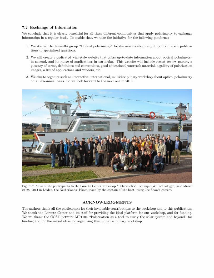
Figure 7. Most of the participants to the Lorentz Center workshop “Polarimetric Techniques & Technology”, held March24-28, 2014 in Leiden, the Netherlands. Photo taken by the captain of the boat, using Joe Shaw’s camera.
ACKNOWLEDGMENTS
The authors thank all the participants for their invaluable contributions to the workshop and to this publication.We thank the Lorentz Center and its staff for providing the ideal platform for our workshop, and for funding.We we thank the COST network MP1104 “Polarisation as a tool to study the solar system and beyond” forfunding and for the initial ideas for organizing this multidisciplinary workshop.

REFERENCES[1] J. S. Tyo, D. L. Goldstein, D. B. Chenault, and J. A. Shaw, “Review of passive imaging polarimetry for remote sensing applications,”
Appl. Opt. 45, pp. 5453–5469, Aug 2006.
[2] F. Snik and C. U. Keller, “Astronomical Polarimetry: Polarized Views of Stars and Planets,” in Planets, Stars and Stellar Sys-tems. Volume 2: Astronomical Techniques, Software and Data, T. D. Oswalt and H. E. Bond, eds., p. 175, 2013.
[3] D. Clarke, Stellar Polarimetry, 2010.
[4] F. Snik, A. Lopez Artiste, and S. Bagnulo 2014.
[5] E. Wolf, Introduction to the Theory of Coherence and Polarization of Light, Cambridge University Press, 2007.
[6] I. J. Hodgkinson and Q. H. Wu, Birefringent Thin Films and Polarizing Elements , World Scientific, 1998.
[7] I. J. Vaughn and B. G. Hoover, “Noise reduction in a laser polarimeter based on discrete waveplate rotations,” Opt. Express 16,pp. 2091–2108, Feb 2008.
[8] D. J. Diner, M. J. Garay, O. V. Kalashnikova, B. E. Rheingans, S. Geier, M. A. Bull, V. M. Jovanovic, F. Xu, C. J. Bruegge, A. Davis,K. Crabtree, and R. A. Chipman, “Airborne multiangle spectropolarimetric imager (airmspi) observations over california during nasa’spolarimeter definition experiment (podex),” 2013.
[9] N. J. Pust and J. A. Shaw, “Dual-field imaging polarimeter using liquid crystal variable retarders,” Appl. Opt. 45, pp. 5470–5478, Aug2006.
[10] P.-Y. Deschamps, F.-M. Breon, M. Leroy, A. Podaire, A. Bricaud, J.-C. Buriez, and G. Seze, “The polder mission: instrument charac-teristics and scientific objectives,” Geoscience and Remote Sensing, IEEE Transactions on 32, pp. 598–615, May 1994.
[11] B. Cairns, E. E. Russell, J. D. LaVeigne, and P. M. W. Tennant, “Research scanning polarimeter and airborne usage for remote sensingof aerosols,” in Polarization Science and Remote Sensing, J. A. Shaw and J. S. Tyo, eds., Society of Photo-Optical InstrumentationEngineers (SPIE) Conference Series 5158, pp. 33–44, Dec. 2003.
[12] R. J. Peralta, C. Nardell, B. Cairns, E. E. Russell, L. D. Travis, M. I. Mishchenko, B. A. Fafaul, and R. J. Hooker, “Aerosol polarimetrysensor for the Glory Mission,” in Society of Photo-Optical Instrumentation Engineers (SPIE) Conference Series, Society of Photo-Optical Instrumentation Engineers (SPIE) Conference Series 6786, Nov. 2007.
[13] D. J. Diner, A. Davis, B. Hancock, S. Geier, B. Rheingans, V. Jovanovic, M. Bull, D. M. Rider, R. A. Chipman, A.-B. Mahler, andS. C. McClain, “First results from a dual photoelastic-modulator-based polarimetric camera,” Appl. Opt. 49, pp. 2929–2946, May 2010.
[14] G. van Harten, F. Snik, J. H. H. Rietjens, J. M. Smit, J. de Boer, R. Diamantopoulou, O. P. Hasekamp, D. M. Stam, C. U. Keller, E. C.Laan, A. L. Verlaan, W. A. Vliegenthart, R. Ter Horst, R. Navarro, K. Wielinga, S. Hannemann, S. G. Moon, and R. Voors, “Prototypingfor the Spectropolarimeter for Planetary EXploration (SPEX): calibration and sky measurements,” in Society of Photo-Optical In-strumentation Engineers (SPIE) Conference Series, Society of Photo-Optical Instrumentation Engineers (SPIE) Conference Series8160, Sept. 2011.
[15] C. U. Keller, “Instrumentation for astrophysical spectropolarimetry,” in Astrophysical Spectropolarimetry, J. Trujillo-Bueno,F. Moreno-Insertis, and F. Sanchez, eds., pp. 303–354, 2002.
[16] J. Tinbergen, Astronomical Polarimetry, Sept. 1996.
[17] M. Rodenhuis, H. Canovas, S. V. Jeffers, M. de Juan Ovelar, M. Min, L. Homs, and C. U. Keller, “The extreme polarimeter: design,performance, first results and upgrades,” in Society of Photo-Optical Instrumentation Engineers (SPIE) Conference Series, Societyof Photo-Optical Instrumentation Engineers (SPIE) Conference Series 8446, Sept. 2012.
[18] H.-M. Schmid, M. Downing, R. Roelfsema, A. Bazzon, D. Gisler, J. Pragt, C. Cumani, B. Salasnich, A. Pavlov, A. Baruffolo, J.-L.Beuzit, A. Costille, S. Deiries, K. Dohlen, C. Dominik, E. Elswijk, M. Feldt, M. Kasper, D. Mouillet, C. Thalmann, and F. Wildi, “Testsof the demodulating CCDs for the SPHERE / ZIMPOL imaging polarimeter,” in Society of Photo-Optical Instrumentation Engineers(SPIE) Conference Series, Society of Photo-Optical Instrumentation Engineers (SPIE) Conference Series 8446, Sept. 2012.
[19] D. M. Harrington and J. R. Kuhn, “Precision and Resolution in Stellar Spectropolarimetry,” in Solar Polarization 6, J. R. Kuhn,D. M. Harrington, H. Lin, S. V. Berdyugina, J. Trujillo-Bueno, S. L. Keil, and T. Rimmele, eds., Astronomical Society of the PacificConference Series 437, p. 257, Apr. 2011.
[20] O. Kochukhov, V. Makaganiuk, and N. Piskunov, “Least-squares deconvolution of the stellar intensity and polarization spectra,” A&A524, p. A5, Dec. 2010.
[21] D. M. Harrington, J. R. Kuhn, and S. Hall, “Deriving Telescope Mueller Matrices Using Daytime Sky Polarization Observations,”PASP 123, pp. 799–811, July 2011.
[22] W. B. Sparks, J. H. Hough, L. Kolokolova, T. A. Germer, F. Chen, S. DasSarma, P. DasSarma, F. T. Robb, N. Manset, I. N. Reid,F. D. Macchetto, and W. Martin, “Circular polarization in scattered light as a possible biomarker,” JQSRT 110, pp. 1771–1779, Sept.2009.
[23] T. Novikova, A. Pierangelo, A. D. Martino, A. Benali, and P. Validire, “Polarimetric imaging for cancer diagnosis and staging,” Opt.Photon. News 23, pp. 26–33, Oct 2012.
[24] N. Ghosh and I. A. Vitkin, “Tissue polarimetry: concepts, challenges, applications, and outlook,” Journal of Biomedical Optics 16(11),pp. 110801–110801–29, 2011.
[25] S. L. Jacques, “Optical properties of biological tissues: a review,” Physics in Medicine and Biology 58(11), p. R37, 2013.
[26] A. Pierangelo, A. Nazac, A. Benali, P. Validire, H. Cohen, T. Novikova, B. H. Ibrahim, S. Manhas, C. Fallet, M.-R. Antonelli, andA.-D. Martino, “Polarimetric imaging of uterine cervix: a case study,” Opt. Express 21, pp. 14120–14130, Jun 2013.
[27] M. Axer, K. Amunts, D. Grssel, C. Palm, J. Dammers, H. Axer, U. Pietrzyk, and K. Zilles, “A novel approach to the human connectome:Ultra-high resolution mapping of fiber tracts in the brain,” NeuroImage 54(2), pp. 1091 – 1101, 2011.
[28] J. J. Gil, “Review on mueller matrix algebra for the analysis of polarimetric measurements,” Journal of Applied Remote Sensing 8(1),p. 081599, 2014.
[29] J. Desroches, D. Pagnoux, F. Louradour, and A. Barthelemy, “Fiber-optic device for endoscopic polarization imaging,” Opt. Lett. 34,pp. 3409–3411, Nov 2009.
[30] J. Fade and M. Alouini, “Depolarization remote sensing by orthogonality breaking,” Phys. Rev. Lett. 109, p. 043901, Jul 2012.
[31] M. Rodenhuis, F. Snik, G. van Harten, J. Hoeijmakers, R. Joseph, and C. U. Keller, “Five-dimensional optical instrumentation:combining polarimetry with time-resolved integral-field spectroscopy,” in Society of Photo-Optical Instrumentation Engineers (SPIE)Conference Series, Society of Photo-Optical Instrumentation Engineers (SPIE) Conference Series 9099, 2014.
[32] M. W. Kudenov, M. J. Escuti, E. L. Dereniak, and K. Oka, “White-light channeled imaging polarimeter using broadband polarizationgratings,” Appl. Opt. 50, pp. 2283–2293, May 2011.

[33] E. Compain and B. Drevillon, “Broadband division-of-amplitude polarimeter based on uncoated prisms,” Appl. Opt. 37, pp. 5938–5944,Sep 1998.
[34] K. Oka and T. Kaneko, “Compact complete imaging polarimeter using birefringent wedge prisms,” Opt. Express 11, pp. 1510–1519,Jun 2003.
[35] W. Sparks, T. A. Germer, J. W. MacKenty, and F. Snik, “Compact and robust method for full stokes spectropolarimetry,” Appl. Opt.51, pp. 5495–5511, Aug 2012.
[36] K. Oka and T. Kato, “Spectroscopic polarimetry with a channeled spectrum,” Opt. Lett. 24, pp. 1475–1477, Nov 1999.
[37] F. Snik, T. Karalidi, and C. U. Keller, “Spectral modulation for full linear polarimetry,” Appl. Opt. 48, pp. 1337–1346, Mar 2009.
[38] K. H. Nordsieck, “A Simple Polarimetric System for the Lick Observatory Image-Tube Scanner,” PASP 86, p. 324, June 1974.
[39] A. S. Alenin and J. S. Tyo, “Generalized channeled polarimetry,” J. Opt. Soc. Am. A 31, pp. 1013–1022, May 2014.
[40] G. Anna, H. Sauer, F. Goudail, and D. Dolfi, “Fully tunable active polarization imager for contrast enhancement and partial polarime-try,” Appl. Opt. 51, pp. 5302–5309, Jul 2012.
[41] N. Hagen, K. Oka, and E. L. Dereniak, “Snapshot mueller matrix spectropolarimeter,” Opt. Lett. 32, pp. 2100–2102, Aug 2007.
[42] J. S. Tyo, “Design of optimal polarimeters: Maximization of signal-to-noise ratio and minimization of systematic error,” Appl. Opt.41, pp. 619–630, Feb 2002.
[43] D. S. Sabatke, M. R. Descour, E. L. Dereniak, W. C. Sweatt, S. A. Kemme, and G. S. Phipps, “Optimization of retardance for acomplete stokes polarimeter,” Opt. Lett. 25, pp. 802–804, Jun 2000.
[44] J. C. del Toro Iniesta and M. Collados, “Optimum Modulation and Demodulation Matrices for Solar Polarimetry,” Appl. Opt. 39,pp. 1637–1642, 2000.
[45] D. M. Harrington, J. R. Kuhn, C. Sennhauser, E. J. Messersmith, and R. J. Thornton, “Achromatizing a Liquid-Crystal Spectropo-larimeter: Retardance vs. Stokes-Based Calibration of HiVIS,” PASP 122, pp. 420–438, Apr. 2010.
[46] F. Goudail, “Noise minimization and equalization for stokes polarimeters in the presence of signal-dependent poisson shot noise,” Opt.Lett. 34, pp. 647–649, Mar 2009.
[47] A. D. Martino, Y.-K. Kim, E. Garcia-Caurel, B. Laude, and B. Drevillon, “Optimized mueller polarimeter with liquid crystals,” Opt.Lett. 28, pp. 616–618, Apr 2003.
[48] J. Zallat, S. Aınouz, and M. P. Stoll, “Optimal configurations for imaging polarimeters: impact of image noise and systematic errors,”Journal of Optics A: Pure and Applied Optics 8(9), p. 807, 2006.
[49] A. Peinado, A. Lizana, J. Vidal, C. Iemmi, and J. Campos, “Optimization and performance criteria of a stokes polarimeter based ontwo variable retarders,” Opt. Express 18, pp. 9815–9830, May 2010.
[50] W.-L. Hsu, G. Myhre, K. Balakrishnan, N. Brock, M. Ibn-Elhaj, and S. Pau, “Full-stokes imaging polarimeter using an array of ellipticalpolarizer,” Opt. Express 22, pp. 3063–3074, Feb 2014.
[51] M. W. Kudenov, M. E. L. Jungwirth, E. L. Dereniak, and G. R. Gerhart, “White light sagnac interferometer for snapshot linearpolarimetric imaging,” Opt. Express 17, pp. 22520–22534, Dec 2009.
[52] D. Clarke and D. Neumayer, “Experiments with a novel CCD stellar polarimeter,” A&A 383, pp. 360–366, Jan. 2002.
[53] S. Tomczyk, R. Casini, A. G. de Wijn, and P. G. Nelson, “Wavelength-diverse polarization modulators for Stokes polarimetry,”Appl. Opt. 49, pp. 3580–3586, 2010.
[54] P. A. Letnes, I. S. Nerbø, L. M. S. Aas, P. G. Ellingsen, and M. Kildermo, “Fast and optimal broad-band Stokes/Mueller polarimeterdesign by the use of a genetic algorithm,” Optics Express 18, pp. 23095–23103, 2010.
[55] F. Snik, G. van Harten, R. Navarro, P. Groot, L. Kaper, and A. de Wijn, “Design of a full-Stokes polarimeter for VLT/X-shooter,” inSociety of Photo-Optical Instrumentation Engineers (SPIE) Conference Series, Society of Photo-Optical Instrumentation Engineers(SPIE) Conference Series 8446, Sept. 2012.
[56] G. Van Harten, F. Snik, C. U. Keller, and A. G. de Wijn, “Design Analysis of a Polychromatic Full-Stokes Polarization Modulator forthe 300–2500 nm Wavelength Range.” Appl. Opt. (to be submitted), 2014.
[57] J. Hou, A. G. de Wijn, and S. Tomczyk, “Design and measurement of the Stokes polarimeter for the COSMO K-coronagraph,” ApJ774, p. 85, Sept. 2013.
[58] J. Tyo, Z. Wang, S. Johnson, and B. Hoover, “Design and optimization of partial mueller matrix polarimeters,” Appl. Opt. 49,pp. 2326–2333, Apr 2010.
[59] G. Anna, F. Goudail, P. Chavel, and D. Dolfi, “On the influence of noise statistics on polarimetric contrast optimization,” Appl. Opt.51, pp. 1178–1187, Mar 2012.
[60] S. Bagnulo, M. Landolfi, J. D. Landstreet, E. Landi Degl’Innocenti, L. Fossati, and M. Sterzik, “Stellar Spectropolarimetry withRetarder Waveplate and Beam Splitter Devices,” PASP 121, pp. 993–1015, Sept. 2009.
[61] M. Semel, J. Donati, and D. E. Rees, “Zeeman-Doppler imaging of active stars. 3: Instrumental and technical considerations,” A&A278, pp. 231–237, Oct. 1993.
[62] R. Casini, A. G. de Wijn, and P. G. Judge, “Analysis of seeing-induced polarization cross-talk and modulation scheme performance,”The Astrophysical Journal 757(1), p. 45, 2012.
[63] C. F. LaCasse, T. Ririe, R. A. Chipman, and J. S. Tyo, “Spatio-temporal modulated polarimetry,” 2011.
[64] J. Craven and M. W. Kudenov, “False signature reduction in channeled spectropolarimetry,” Optical Engineering 49(5), pp. 053602–053602–10, 2010.
[65] C. F. LaCasse, R. A. Chipman, and J. S. Tyo, “Band limited data reconstruction in modulated polarimeters,” Opt. Express 19,pp. 14976–14989, Aug 2011.
[66] C. F. LaCasse, J. S. Tyo, and R. A. Chipman, “Role of the null space of the drm in the performance of modulated polarimeters,” Opt.Lett. 37, pp. 1097–1099, Mar 2012.
[67] M. de Juan Ovelar, F. Snik, and C. U. Keller, “M&m’s: an error budget and performance simulator code for polarimetric systems,” inSociety of Photo-Optical Instrumentation Engineers (SPIE) Conference Series, Society of Photo-Optical Instrumentation Engineers(SPIE) Conference Series 8160, Sept. 2011.
[68] C. U. Keller, “Recent Progress in Imaging Polarimetry,” Sol. Phys. 164, pp. 243–252, Mar. 1996.
[69] H. Socas-Navarro, D. Elmore, A. Asensio Ramos, and D. M. Harrington, “Characterization of telescope polarization properties acrossthe visible and near-infrared spectrum. Case study: the Dunn Solar Telescope,” A&A 531, p. A2, July 2011.
[70] E. Compain, S. Poirier, and B. Drevillon, “General and self-consistent method for the calibration of polarization modulators, polarime-ters, and mueller-matrix ellipsometers,” Appl. Opt. 38, pp. 3490–3502, Jun 1999.

[71] G. Capobianco, S. Fineschi, G. Massone, E. Balboni, A. M. Malvezzi, G. Crescenzio, L. Zangrilli, P. Calcidese, E. Antonucci, and M. Pa-trini, “Electro-optical polarimeters for ground-based and space-based observations of the solar K-corona,” in Society of Photo-OpticalInstrumentation Engineers (SPIE) Conference Series, Society of Photo-Optical Instrumentation Engineers (SPIE) Conference Se-ries 8450, Sept. 2012.
[72] N. Uribe-Patarroyo, A. Alvarez-Herrero, P. Garcıa Parejo, J. Vargas, R. L. Heredero, R. Restrepo, V. Martınez Pillet, J. C. Del ToroIniesta, A. Lopez, S. Fineschi, G. Capobianco, M. Georges, M. Lopez, G. Boer, and I. Manolis, “Space-qualified liquid-crystal variableretarders for wide-field-of-view coronagraphs,” in Society of Photo-Optical Instrumentation Engineers (SPIE) Conference Series,Society of Photo-Optical Instrumentation Engineers (SPIE) Conference Series 8148, Sept. 2011.
[73] R. K. Komanduri, K. F. Lawler, and M. J. Escuti, “Multi-twist retarders: broadband retardation control using self-aligning reactiveliquid crystal layers,” Opt. Express 21, pp. 404–420, Jan 2013.
[74] C. Oh and M. J. Escuti, “Achromatic diffraction from polarization gratings with high efficiency,” Opt. Lett. 33, pp. 2287–2289, Oct2008.
[75] M. N. Miskiewicz and M. J. Escuti 2014.
[76] J. S. Tyo, C. F. LaCasse, and B. M. Ratliff, “Total elimination of sampling errors in polarization imagery obtained with integratedmicrogrid polarimeters,” Opt. Lett. 34, pp. 3187–3189, Oct 2009.
[77] D. A. LeMaster and K. Hirakawa, “Improved microgrid arrangement for integrated imaging polarimeters,” Opt. Lett. 39, pp. 1811–1814,Apr 2014.
[78] H. Lin and A. Versteegh, “VisIRIS: a visible/IR imaging spectropolarimeter based on a birefringent fiber-optic image slicer,” in Societyof Photo-Optical Instrumentation Engineers (SPIE) Conference Series, Society of Photo-Optical Instrumentation Engineers (SPIE)Conference Series 6269, July 2006.
[79] P. Marconnet, L. Gendre, A. Foulonneau, and L. Bigue, “Cancellation of motion artifacts caused by a division-of-time polarimeter,” inSociety of Photo-Optical Instrumentation Engineers (SPIE) Conference Series, Society of Photo-Optical Instrumentation Engineers(SPIE) Conference Series 8160, Sept. 2011.
[80] S. Faisan, C. Heinrich, F. Rousseau, A. Lallement, and J. Zallat, “Joint filtering estimation of stokes vector images based on a nonlocalmeans approach,” J. Opt. Soc. Am. A 29, pp. 2028–2037, Sep 2012.
[81] G. Anna, N. Bertaux, F. Galland, F. Goudail, and D. Dolfi, “Joint contrast optimization and object segmentation in active polarimetricimages,” Opt. Lett. 37, pp. 3321–3323, Aug 2012.
[82] J. S. Tyo, J. E. N. Pugh, and N. Engheta, “Colorimetric representations for use with polarization-difference imaging of objects inscattering media,” J. Opt. Soc. Am. A 15, pp. 367–374, Feb 1998.
[83] F. Snik, “Measure aerosols with ispex on your smartphone,” SPIE newsroom , 2013.