Embed Size (px)
Citation preview

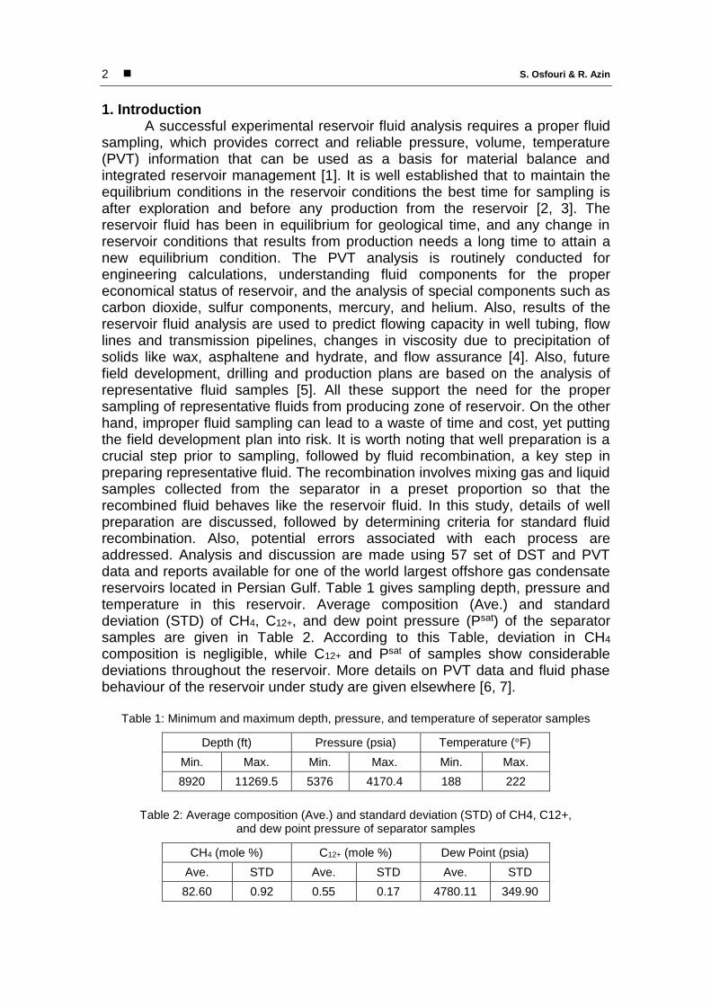
Journal of Oil, Gas and Petrochemical Technology Vol. 3, No. 1, pp. 1-14 1
An Overview of Challenges and Errors in
Sampling and Recombination of Gas Condensate Fluids
Shahriar Osfouri 1, *, Reza Azin 2
1. Department of Chemical Engineering, Faculty of Oil, Gas, and Petrochemical Engineering,
Persian Gulf University, Bushehr, Iran 2. Department of Petroleum Engineering, Faculty of Oil, Gas, and Petrochemical Engineering,
Persian Gulf University, Bushehr, Iran
ARTICLE INFO
ABSTRACT
Article history: Received: November 01, 2014 Accepted: December 26, 2015 Keywords: Sampling Recombination Gas condensate Separator Equilibrium * Corresponding author E-mail: [email protected] Tel.: +98 77 31222400 Fax: +98 77 33441495
A proper understanding of reservoir fluid phase behavior is the first crucial step in the development and production of an oil/gas field. This paper addresses the challenges and errors associated with the fluid sampling that may arise before, during and after the sampling operation. For this aim, DST and PVT data of exploration and production wells of a supergiant offshore gas condensate reservoir were analyzed. It was found that well conditioning and flow stability are essential before sampling. The main sources of error during the sampling include separator instability, lack of vapor-liquid equilibrium, volume ratio of separator outlets, and the presence of contaminants. Analysis of separator outlet streams further indicated deviation from equilibrium for some wells, which can have direct impact on dew-point pressure and condensate gas ratio (CGR) prediction of well stream. Improper fluid handling, oil and gas leakage, and the presence of corrosive compounds can severely affect the quality of the recombined fluid.
S. Osfouri & R. Azin 2
1. Introduction A successful experimental reservoir fluid analysis requires a proper fluid
sampling, which provides correct and reliable pressure, volume, temperature (PVT) information that can be used as a basis for material balance and integrated reservoir management [1]. It is well established that to maintain the equilibrium conditions in the reservoir conditions the best time for sampling is after exploration and before any production from the reservoir [2, 3]. The reservoir fluid has been in equilibrium for geological time, and any change in reservoir conditions that results from production needs a long time to attain a new equilibrium condition. The PVT analysis is routinely conducted for engineering calculations, understanding fluid components for the proper economical status of reservoir, and the analysis of special components such as carbon dioxide, sulfur components, mercury, and helium. Also, results of the reservoir fluid analysis are used to predict flowing capacity in well tubing, flow lines and transmission pipelines, changes in viscosity due to precipitation of solids like wax, asphaltene and hydrate, and flow assurance [4]. Also, future field development, drilling and production plans are based on the analysis of representative fluid samples [5]. All these support the need for the proper sampling of representative fluids from producing zone of reservoir. On the other hand, improper fluid sampling can lead to a waste of time and cost, yet putting the field development plan into risk. It is worth noting that well preparation is a crucial step prior to sampling, followed by fluid recombination, a key step in preparing representative fluid. The recombination involves mixing gas and liquid samples collected from the separator in a preset proportion so that the recombined fluid behaves like the reservoir fluid. In this study, details of well preparation are discussed, followed by determining criteria for standard fluid recombination. Also, potential errors associated with each process are addressed. Analysis and discussion are made using 57 set of DST and PVT data and reports available for one of the world largest offshore gas condensate reservoirs located in Persian Gulf. Table 1 gives sampling depth, pressure and temperature in this reservoir. Average composition (Ave.) and standard deviation (STD) of CH4, C12+, and dew point pressure (Psat) of the separator samples are given in Table 2. According to this Table, deviation in CH4 composition is negligible, while C12+ and Psat of samples show considerable deviations throughout the reservoir. More details on PVT data and fluid phase behaviour of the reservoir under study are given elsewhere [6, 7].
Table 1: Minimum and maximum depth, pressure, and temperature of seperator samples
Depth (ft) Pressure (psia) Temperature (°F)
Min. Max. Min. Max. Min. Max.
8920 11269.5 5376 4170.4 188 222
Table 2: Average composition (Ave.) and standard deviation (STD) of CH4, C12+,
and dew point pressure of separator samples
CH4 (mole %) C12+ (mole %) Dew Point (psia)
Ave. STD Ave. STD Ave. STD
82.60 0.92 0.55 0.17 4780.11 349.90

Journal of Oil, Gas and Petrochemical Technology Vol. 3, No. 1, pp. 1-14
3
2. Well Conditioning Well conditioning implies removing the fluid remained in borehole and
replacing the reservoir fluid. When reservoir pressure falls below the initial saturation pressure, the properties of reservoir fluid change considerably. The change in fluid properties due to pressure drop becomes more pronounced in the borehole. As pressure drop increases, changes in fluid properties extend farther in the reservoir, depending on production time and the value of bottom hole pressure drops below reservoir pressure [3]. The flow rate during well conditioning should be low enough to minimize the dradown pressure by using the lowest possible choke size [8]. On the other side, the flowing velocity should be higher than the critical velocity to prevent the liquid holdup in well [9, 10].
According to steady-state flow theory, the static experimental analysis of fluid samples can simulate the dynamic behavior of reservoir fluids when samples are collected at steady-state conditions [3, 11, 12]. The steady-state sampling requires that parameters such as wellhead and separator temperature and pressure, solids flow rate, flow rates of separator gas and separator liquid, and gas-oil ratio be at stable conditions [9]. Figure 1 shows the fluctuation of these parameters in a well being condition for samppling (sample number: W-1).
(b) (a)
(d) (c)
Figure 1: Variation of key parameters with respect to time for a conditioned well (sample number: W-1): (a) well head pressure and temperature, (b) separator
pressure and temperature, (c) separator oil and gas rates, (d) basic sediment and water

S. Osfouri & R. Azin 4
The acceptable range of fluctuations for each property is discussed in references [6, 13] and is also shown in Table 3. It is suggested that well is shut-in at least 24 hours prior to sampling [3]. Normally, the well is prepared by gradual decreasing the flow rate to make sure that the well is clean enough and collect samples at the smallest lift flow rate. In the case of the saturated gas condensate reservoirs, taking too long time may result in the accumulation of the condensate. In this case, it is suggested to collect the samples right after the well stability [14].
Table 3: Acceptable range of fluctuations of well head pressure,
separator pressure, oil rate, and BS&W
Well head pressure (psia) Separator pressure (psia) Oil rate (bbl/day) BS&W (%)
± 20 ± 15 ± 10 Max. 5%
Figure 2 shows variations in wellhead pressure and temperature for
sample W-2 (2-a) and separator oil and gas rates for sample W-3 (2-b). These figures are examples of data that do not fall within the acceptable range, implying that the well and separator have not reached the stability conditions. As a result, the collected samples cannot represent the reservoir fluid.
(a) (b)
Figure 2: Flactuation of parameters for unsatisified condition of represantative fluid sampling:
(a) well head pressure and temperature (sample number: W-2), (b) separator oil and gas
rates (sample number: W-3)
3. Sampling
Generally, there are three types of fluid sampling applied in upstream oil and gas operations, i.e. surface, sub-surface and well head sampling. Surface sampling is conducted in a surface separator and is normally applied extensively in many hydrocarbon reservors, including gas condensate, saturated oil, high-viscosity oils and foamy oils. There are three techniques for surface sampling, known as standard, isokinetic and mini-laboratory (Thorton)

Journal of Oil, Gas and Petrochemical Technology Vol. 3, No. 1, pp. 1-14
5
sampling [15]. For gas-condensate samples, the standard technique is recommended. However, if the gas is suspected to have liquid carry over, the isokinetic technique is preferred [16, 17]. The Thorton sampling is a small portable laboratory used for sampling from gas condensat wells. However, this technique is more expensive than the separator sampling [15]. Overall, surface sampling is relatively simple and cheap compared to the subsurface and Thorton sampling. In this technique, well production is not interrupted and fluid storage does not occur in the well. Also, it can be applied for the cases where water is present in the tubing. In addition, the collected well fluid does not need to be in single phase in the wellbore. Moreover, separator fluid sampling may be performed repeatedly in high volumes to study such phenomena as asphaltene deposition, wax formation, emulsions, hydrates and corrosion.
In subsurface sampling, the sampling device is moved via the wellhead down to sampling point. The well fluid is collected in sampling device as a result of the high pressure gradient, and moved up by pulling the device out of the well. The collected sample is then pressurized to become single phase and transferred to laboratory in special vessels. The subsurface sampling can be performed right after drilling and well preparation. It is worth noting that the fluid should be at single phase in this technique to make sure that all components have been collected properly [18]. In this technique, the separator and measuring devices for fluid flow are not required. Also, human errors associated with the recombination are eliminated, as there is no need to recombine the collected fluids. In addition, collected samples have less volume compared to surface sampling; consequently, fluid handling to laboratory is easier. The wellhead sampling is not as common as the surface and sub-surface sampling. However, it has valuable potentials to replace the other techniques. If the well fluid is single phase at wellhead temperature and pressure, wellhead sampling can be conducted as a reliable technique with more simplicity. This technique can be applied to undersaturated oil and dry gas samples [19].
4. Challenges of fluid sampling and recombination
The main objective of fluid recombination is to obtain original composition of reservoir fluid. In this operation, the separator gas and liquid effluents are mixed with reservoir gas oil ratio (GOR) proportion. It is crucial that the recombined streams must be at equilibrium during the sampling [13]. Thermodynamic equilibrium is a key factor for a successful sampling. Figure 3 shows phase diagram for separator gas (a), separator oil (b) and recombined fluid (c) [20]. According to this figure, the separator gas and liquid should be collected at saturation conditions, i.e. their dew and bubble pressures. In addition, they should be single phase during transfer into the sampling vessles. For separator gas, this means that the sample temperature should not be lower than the separator temperature (line 1 on figure 3-a) or throttled before entering the sampling vessel, as simultaneous pressure and temperature drop changes the fluid conditions in the two-phase region (line 2 on Figure 3-a). Similarly, the separator liquid should be collected at equlibrium conditions with neither a drop in pressure (line 2 on figure 3-b) nor an increase in temperature (line 1 on Figure 3-b).

S. Osfouri & R. Azin 6
Figure 4 compares the separator conditions, sample number: W-4, with ideal thermodynamic conditions that occur at the intersection between the two curves. The mismatch between the two points indicates deviation from the equilibrium conditions, which is about 120 (psia) for this case.
(b) (a)
(c)
Figure 3. Phase diagram of gas (a), oil (b) and representative reservoir fluid (c) [20]
Figure 4: Phase diagram of separator gas and oil (saple number: W-4) in
non-equilibrium condition

Journal of Oil, Gas and Petrochemical Technology Vol. 3, No. 1, pp. 1-14
7
The original composition of reservoir fluid is readily determined in dry and
wet gas reservoirs through recombination. For gas condensate reservoirs, this
technique is applicable only when the reservoir pressure is above the original
dew point pressure. When the reservoir pressure falls below the dew point
during the production, recombining separator streams does not result in original
reservoir fluid and produces large errors when conducted at these pressures. In
1994, two techniques were proposed by Reffstrup and Olsen [21] and Fevang
et al. [18] to determine the original fluid composition for a depleted reservoir.
Reffstrup and Olsen [21] described the producing fluid by using an equation of
state and added incremental volumes of produced condensate to enrich the gas
stream until the original dew point pressure was reached. The second technique
proposed by Fevang et al. [18] applies to gas condensate reservoirs with initial
oil rim when both oil and gas zones are produced simultaneously. This
technique involves the following steps:
• Recombining producing gas and condensate to reach well head
producing composition;
• Converting the recombined fluid to prevailing reservoir temperature and
pressure;
• Producing all liquid condensate that is formed in this process;
• Producing part of the equilibrium gas;
• Gradual injecting equilibrium condensate into equilibrium gas until dew
point pressure of recombined fluid approaches that of the original fluid.
This technique is an experimental procedure and has no theoretical
background. Moreover, this technique has not been tested in field conditions.
The collection of samples that do not represent reservoir fluid can lead to
analyses which affect all the subsequent engineering calculations. As
mentioned before, one of the main challenges in fluid sampling from gas
condensate reservoirs is well and separator stability prior to the sampling. Also,
there may be challenges during fluid sampling, e.g. a) when separator
temperature is lower than the surrounding, b) producing fluid contains CO2
and/or H2S, and c) reservoir fluid contains considerable amounts of paraffins
(wax) and asphaltene. When separator temperature falls below the surrounding,
the temperature of sampling vessel should be lowered down to separator
temperature, otherwise entering liquid flashes and part of vessel is occupied by
the flashed vapor. This leads to a decrease in volume of the collected fluid.
Similar problem may occur when insufficient liquid sample is collected.
The presence of CO2 and/or H2S in reservoir fluid can lead to corrosion
in sampling vessel, especially when water is present. In this case, corrosion
resistant vessels should be used for sampling to make sure that fluid
composition remains unchanged while delivering samples to laboratory. Also,
deposition of solid compounds from collected fluids may interfere with sampling
and affect the quality and composition of the collected samples. Paraffinic and
asphaltic oil samples may deposit in reservoir, wellbore, separator and sampling
vessels. Generally, paraffins deposit upon coolong and degassing. Smilarly,

S. Osfouri & R. Azin 8
asphaltic oil samples deposit upon cooling and in contact with light
hydrocarbons. Therefore, pressure and temperature drop should be minimized
to prevent the fluid loss in these systems [2].
Another challenging issue refers to the sampling point. For surface
sampling, it is conducted at points with minimum pressure drop to avoid the
sampling and measurement errors. On the other hand, subsurface samples are
normally collected from the lowest well depth for safety reason and to assure
that its static pressure is higher or equal than the fluid saturation pressure [22].
Presence of water in collected samples is considered as contamination that
should be minimized. Foaming is another challenge that may interfere with fluid
sampling in certain reservoirs that produces stable foam. In these cases, liquid
carry over may appear with separator gas [23]. In addition, such contaminants
as injecting chemicals and drilling mud fluids may downgrade the quality of the
collected samples.
Figure 5 illustrates changes in dew point pressure with gas oil ratio
(GOR) for a gas condensate sample [24]. This is another challenging issue in
recombining oil and gas streams extracted from the gas condensate separator.
According to this Figure, two recombined samples with different compositions
and GOR can result in the same Psat (points a and b on Figure 5). Yet the true
Psat of reservoir fluid (point c) may be much higher than that measured for the
recombined fluid. In other words, relying on GOR may not lead to a
representative recombined fluid.
Figure 5: Variation of dew-point presuure of gas condensate with GOR [24]
Another challenging issue in gas condensate sampling is the non-uniform
behaviour of GOR versus the flow rate. At low rates, the gas stream cannot
carry the liquid condensate produced in the wellbore; consequently, it results in

Journal of Oil, Gas and Petrochemical Technology Vol. 3, No. 1, pp. 1-14
9
an increase in GOR of the producing stream. On the other side, by increasing
the flow rate, condensate banking and GOR decreases. At very high flow rates,
condensate drop-out in the reservoir results in the increase in poducing GOR.
Therefore, there is an optimum flow rate region where GOR remains unchanged
[22].
There are many factors that can adversely affect the quality of the
separator recombined fluid. The key factors address the compositional analysis
of separator gas and liquid streams and proper selection of GOR for mixing
streams to simulate the reservoir fluid [23]. The latter is of special importance
for gas condensate systems. In cases with low separator oil volume, GOR is
largely affected by a loss in liquid volume, which itself causes considerable
deviation from the representative reservoir fluid properties [25].
Formation of condensate bank around the wellbore is another critical
factor that may cause major variations in GOR and PVT properties of the
recombined fluid. In early production, reservoir pressure is higher than dew
point of original fluid, and pressure drop causes liquid drop-out in the area near
the wellbore [3, 26]. The resulting liquid phase does not flow until its saturation
reaches a critical value, which eventually starts flowing as the second phase
alongside gas flow. At steady state, condensate saturation in two-phase region
decreases in such a way that volume of condensate flowing towards wellbore
equals condensate drop-out in reservoir. As a result, the saturation is stabilized
in the area near wellbore and composition of stream that enters the condensate
rim is equal to the composition of mixture flowing towards wellbore. Moreover,
producing GOR is constant at this stage and recombining the separator streams
can represent the reservoir fluid. Many studies have shown that the steady
conditions do not occur. In addition, flowing pressure and pressure gradient in
reservoir near wellbore decrease with time, and the size of the condensate rim
increases gradually [3, 9, 27]. Therefore, preparing a representative fluid is
much more difficult in gas condensate reservoir compared to the crude oil
systems.
5. Sources of error in fluid sampling and recombination
Overall, errors associated with sampling and recombination of reservoir
fluids may be categorized as instrumental, human, contamination and transfer
errors. Instrumental errors include liquid and gas flow measuring devices, e.g.
orifice meters, which are supposed to be properly calibrated prior to the
sampling. Any error in GOR measurement may interfere with laboratory
analyses. For example, improper selection of orifice size in gas flow meter can
cause 50% error in bubble pressure of the recombined sample. Such a large
error suggests the importance of using calibrated measuring devices in
measuring surface flow rates [2]. Other sources of instrumental errors refer to
mechanical factors such as wax and hydrate deposit on orifice meter plate. On
the other hand, the sources of error for in-situ measurement of specific gravity
and compressibility factor are not as important, because these properties are

S. Osfouri & R. Azin 10
measured carefully in the laboratory. However, it is important to know the
calibration conditions and correction factors for gas flow rate.
Another source of error addresses those related to human activities,
which may happen both during field sampling and laboratory testing, causing all
collected samples to be studied in unrealistic conditions no matter how good
quality they have. Errors in recording temperature, pressure, flow rate, sampling
depth, etc. are examples of human error. In practice, sampling depth should be
away from gas-oil, gas-water, and oil-water contact to prevent coning while the
well is undergoing sampling.
The contamination of collected samples is another source of error. For
example, acidizing can reduce condensate bank near the wellbore; however,
this process can release CO2, H2S, and metal ions that can contaminate fluid
samples collected afterwards. Moreover, use of oil-based drilling mud is another
source of contamination in near-wellbore samples [22]. In addition, injection of
the nti-hydrate compounds like methanol or glycol contaminates the collected
fluids. In practice, methanol injection should be stopped before sampling for at
least five times of separator residence time [14]. The specifications of two
contaminated samples with air and two uncontaminated ones with mud and free
water have been shown in Tables 4 and 5, respectively.
Table 4: Two contaminated samples
Sample Number Hydrocarbon sample volume (cc) Air Content (mole%)
W-5 20000 0.54
W-6 20000 0.10
Table 5: Two uncontaminated samples
Sample Number Opening pressure (psia) Free water drained (cc) Volume of mud (cc)
W-7 495 Nil Nil
W-8 497 Nil Nil
The last source of error in fluid smpling and recombination addresses
those related to movement and transfer of collected samples from field to
laboratory. In many cases, collected samples are regarded as dangerous
chemicals that should be moved with special care. Disregarding the local and
international considerations and regulations may have consequences such as
financial penalties and stopping samples. Sampling cylinders should be kept
away from smoke, fire, operating engines and match. All electrical devices can
cause explosion. In the presence of H2S, special corrosion resistant cylinders
must be used. Also, the cylinders must be checked for leakage. To minimize the
risk of any accident, high-pressure cylinders should be placed in special
containers before transfering to laboratory [19].

Journal of Oil, Gas and Petrochemical Technology Vol. 3, No. 1, pp. 1-14
11
6. Conclusion In this work, PVT and DST data of a supergiant offshore gas condensate
well were analyzed to address the challenges and errors associated with
sampling and recombination of the samples in laboratory. Results showed that
well preparation is the key, yet the most challenging step in obtaining
representative reservoir fluid. The well should be stabilized in a step-by-step
flow reduction to ensure the reservoir fluid contaminated with drilling fluid is
removed from well. After that, the flow rate is gradually reduced to prevent the
formation of condensate banking in the reservoir region around the well bore. It
is expected that the offshore wells are not fully stabilized prior to sampling due
to field and equipment restrictions. Therefore, maximum considerations should
be acknowledged for all factors that contribute to well stability. Besides, surface
separators are found as the most convenient and cheapest techniques for
sampling, provided the reservoir pressure remains above the dew point
pressure. However, this technique may suffer from serious errors addressed by
deviation from equilibrum conditions. Analysis of available data revealed that
separator sampling was not conducted at equilibrium conditions for some wells.
This can result in failure in preparing the representative reservoir fluid.
Therefore, it is essential to know and carefully follow all sampling regulations
and procedures before the sampling.
References [1]
[2]
[3]
[4]
[5]
[6]
[7]
[8]
N.R. Nagarajan, M.M. Honarpour, K. Sampath. “Reservoir-Fluid sampling
and Characterization-Key to Efficient Reservoir Management.” Journal of
Petroleum Technology, vol. 59, pp. 80-91, 2007.
American Petroleum Institute, Sampling Petroleum Reservoir Fluids,
2003.
J.W.B. McCain, R.A. Alexander. “Sampling gas-condensate wells.” SPE
Reservoir Engineering, vol. 7, pp. 358-362, 1992.
J. Bon, H.K. Sarma, J.T. Rodrigues, J.G. Bon. “Reservoir-Fluid Sampling
Revisited-A Practical Perspective.” SPE Reservoir Evaluation &
Engineering, vol. 10, pp. 589 - 596, 2007.
J.J. Lawrence, D.M. Chormeyko, C.K. Smith, N.R. Nagarajan.
“Representative Reservoir Fluid Sampling: Challenges, Issues, and
Solutions.” International Petroleum Technology Conference, Kuala
Lumpur, Malaysia, 2008.
S. Osfouri, R. Azin, M. Kiani Zakheradi, S. Gerami. “A Unified Approach
for Quality Control of Drilled Stem Test and PVT Data.” Gas Processing
Journal, vol. 2, pp. 40-50, 2014.
S. Osfouri, R. Azin, A. Mohammadrezaei. “A Modified Four-Coefficient
Model for Plus Fraction Characterization of a Supergiant Gas Condensate
Reservoir.” Gas Technology Journal, vol. 1, pp. 3-11, 2015.
P.L. Moses. “Engineering Applications of Phase Behavior of Crude Oil

S. Osfouri & R. Azin 12
[9]
[10]
[11]
[12]
[13]
[14]
[15]
[16]
[17]
[18]
[19]
[20]
[21]
[22]
[23]
[24]
and Condensate Syatems.” Journal of Petroleum Technology, vol. 38, pp.
715-723, 1986.
T.R. Olmos Torres. “Analysis of Operative Variables for Establishing a
Procedure to Obtain representative Fluid samples in Gas/Condensate
Fields.” SPE Latin American and Caribbean Petroleum Engineering
Conference, Lima, Peru, 2010.
R.P. Sutton, S.A. Cox, J.F. Lea, O.L. Rowlan. “Guidelines for the Proper
Application of Critical Velocity Calculations.” SPE Production and
Operations, vol. 25, pp. 182-194, 2010.
H.G. O'Dell, R.N. Miller. “Successfully Cycling a Low-Permeability High
Yield Gas-Condensate Reservoir.” Journal of Petroleum Technology, vol.
19, pp. 41-47, 1967.
D.D. Fussell. “Single-Well Performance Predictions for Gas Condensate
Reservoirs.” Journal of Petroleum Engineering. vol. 25, pp. 860-870,
1973.
K.S. Pedersen, P.L. Christensen. Phase Behavior of Petroleum Reservoir
Fluids, Taylor & Francis, 2007.
B.J. Moffatt, J.M. Williams. “Identifying and Meeting the Key Needs for
Reservoir Fluid Properties- A Multi-Disciplinary Approach.” SPE Annual
Technical Conference and Exhibition, New Orleans, Luisiana, USA, 1998.
C.H. Whitson. Manual PVT Analysis, NORSK HYDRO, 1998.
S.E. Buckley, J.H. Lightfoot. “Effect of Pressure and Temperature on
Condensation of Distillate from Natural Gas.” Trans. AIME, vol. 142, pp.
232-245, 1941.
J.M. Flaitz, A.S. Parks. “Sampling Gas-Condensate Wells.” Trans. AIME,
vol. 146, pp. 13-27, 1942.
O. Fivang, C.H. Whitson. “Accurate Insitu Compositions in Petroleum
Reservoirs.” European Petroleum Conference, London, United Kingdom,
1994.
Schlumberger. PVTi Reference Manual. 2009.
American Petroleum Institute. API recomended Practice for Sampling
Petroleum Reservoir Fluids, 44, 1966.
J. Reffstrup, H. Olsen. “Evaluation of PVT Data from Low Permeability
Gas Condensate Reservoirs.” North Sea Oil and Gas Reservoirs-III, pp.
289-296, 1994.
H. Kool, M. Azari, M.Y. Soliman, M.A. Proett, C.A. Irani, B. Dybdahl.
“Testing of Gas Condensate Reservoirs-Sampling, Test design and
Analysis.” SPE Asia Pacific Oil and Gas Conference and Exhibition,
Jakarta, Indonesia, 2001.
J.M. Williams. “Fluid Sampling Under Adverse Conditions.” Oil and Gas
Science and Technology-Rev. IFP, vol. 53, pp. 355-365, 1998.
R.H. Olds, B.H. Sage, W.N. Lacey. “Volumetric and viscosity studies of oil
and gas from a San Joaquin valley Field.” Trans. AIME, vol. 179, pp. 287-
302, 1949.

Journal of Oil, Gas and Petrochemical Technology Vol. 3, No. 1, pp. 1-14
13
[25]
[26]
[27]
L. Fan, B.W. Harris, A. Jamaluddin, J. Kamath, R. Mott, G.A. Pope, A.
Shandrygin, C.H. Whitson. “Understanding gas-condensate reservoirs.”
Oilfiled Review, vol. 17, pp. 14-27, 2005.
R. Mott. “Calculating Well Deliverability in Gas Condensate Reservoirs.”
10th European Symposium on Improved Oil Recovery, Brighton, United
Kingdom, 1999.
A.H. El-Bani, J.W.D. McCain. “Sampling Volatile Oil Wells.” SPE
Production and Operations Symposium, Oklahoma City, Oklahoma, USA,
2001.

S. Osfouri & R. Azin 14
گيريها و خطاهاي فرايند نمونهبررسي چالش
و ترکيب مجدد سياالت گاز ميعاني
2 رضا آذين، ، *1 شهريار عصفوري
نفت، گاز و پتروشیمی، دانشگاه خلیج فارس، بوشهر، ایران ةیمی، دانشکدگروه مهندسی ش. 1 بوشهر، ایران نفت، گاز و پتروشیمی، دانشگاه خلیج فارس، ةگروه مهندسی نفت، دانشکد. 2
چكيده مشخصات مقاله
مقاله: ةتاريخچ
1131آبان 11: دریافت
1131دی 5: پذیرش نهایی
برداری بهرهتوسعه و ةدرک مناسب رفتار فازی سیال مخزن اولین مرحل
ها و خطاهایی در این مطالعه چالشباشد. می گازی یک میدان نفتی/از
گیری ایجاد شود ز عملیات نمونهقبل، حین و بعد اکه ممکن است است
دمای -حجم-های ساق مته حفاری و فشارداده مورد بررسی قرار گرفت.
های اکتشافی و تولیدی یکی از مخازن فوق عظیم گاز میعانی مورد چاه
تحلیل قرار گرفت. مشخص گردید که تثبیت چاه و پایداری جریان قبل
گیری شامل در حین نمونهگیری الزامی است. منابع اصلی خطا از نمونه
بخار، نسبت حجمی -کننده، فقدان تعادل مایعناپایداری تفکیک
باشند. آنالیز ها میکننده و حضور آالیندههای خروجی تفکیکجریان
ها انحراف از حالت تعادل کننده برخی از چاههای خروجی تفکیکجریان
تواند به طور مستقیم بر روی فشار نقطه را نشان داد، که این مهم می
بینی نسبت میعانات به گاز تأثیر داشته باشد. انتقال شبنم و پیش
نامناسب سیال، نشت نفت و گاز، و حضور ترکیبات خورنده به شدت
تواند بر کیفیت سیال ترکیب مجدد اثرگذار باشد.می
کلمات کليدي:
نمونه گیری
ترکیب مجدد
انیسیال گاز میع
تفکیک کننده
تعادل
دار مکاتبات؛* عهده
[email protected]رایانامه:
+ 39 77 11222111 تلفن:
+ 39 77 11111135 دورنگار: