Embed Size (px)
Citation preview

AN OPEN SOURCE GRAPHICS ENGINE
FOR THREE-DIMENSIONAL VIDEO GAMES
A Project
Presented to the
Faculty of
California State University,
San Bernardino
In Partial Fulfillment
of the Requirements for the Degree
Master of Science
in
Computer Science
by
David Lee Gardner Stover
June 2010
AN OPEN SOURCE GRAPHICS ENGINE
FOR THREE-DIMENSIONAL VIDEO GAMES
A Project
Presented to the
Faculty of
California State University,
San Bernardino
by
David Lee Gardner Stover
June 2010
Approved by:
David Turner, Advisor, Computer Scienceand Engineering
Date
Arturo I. Concepcion
Tong Yu

© 2010 David Lee Gardner Stover

ABSTRACT
Mythic is a new three-dimensional (3D) game being developed at CSUSB. To support
Mythic, a new game engine called Geng, which is derived from “game” and “engine”,
is being developed in the School of Computer Science and Engineering at CSUSB.
Geng consists of several modules, including core graphics, physics, artificial intelli-
gence, and a high-level application programming interface (API). The focus of this
master’s project is the development of the Geng core graphics engine, which is called
the Multi-platform All-purpose Graphics Engine (MAGE). The platforms supported
by MAGE include Windows, Linux, Mac OS X, and the iPhone 3GS. For Windows
platforms, Mage provides support for both Direct3D and OpenGL, the two leading
lower level APIs for 3D graphics development. The architecture of MAGE is based on
a unified 3D graphics API that hides the specific implementation details of OpenGL
and Direct3D. MAGE also provides support for keyframe animation, Cg vertex and
fragment shaders, GLSL vertex and fragment shaders, loading static models stored
in the Collada file format, loading static and dynamic models stored in Microsoft’s
X file format, support for graphical user interface (GUI) elements, support for video,
support for text, and support for 3D picking. Although MAGE has been developed
within the context of Geng, it is not dependent on Geng, and therefore can be used
as the core graphics engine for other applications as well.
iii

ACKNOWLEDGEMENTS
There are many people I would like to thank for helping me with this project.
First and foremost is my project advisor, Dr. Turner. He gave me a lot of encour-
agement and advice along the way. I would also like to thank my committee members
Dr. Concepcion and Dr. Yu. They also provided tremendous support. I would like
to thank Dr. Mendoza, my graduate advisor.
Last but not least, I would like to thank my family. My mother and father provided
encouragement. My wife provided love and support. My children, Evan and Kyle,
provided inspiration.
This work is supported by National Science Foundation CPath Award No. CNS-
0938964.
iv
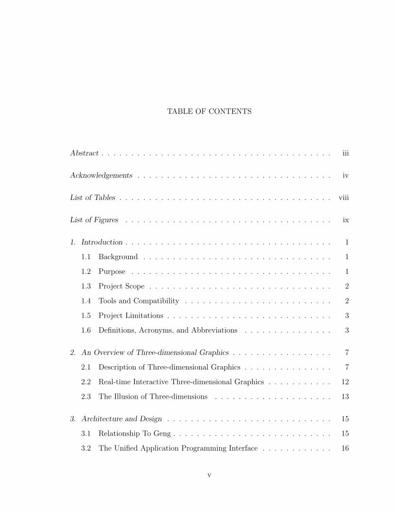
TABLE OF CONTENTS
Abstract . . . . . . . . . . . . . . . . . . . . . . . . . . . . . . . . . . . . . . . iii
Acknowledgements . . . . . . . . . . . . . . . . . . . . . . . . . . . . . . . . . iv
List of Tables . . . . . . . . . . . . . . . . . . . . . . . . . . . . . . . . . . . . viii
List of Figures . . . . . . . . . . . . . . . . . . . . . . . . . . . . . . . . . . . ix
1. Introduction . . . . . . . . . . . . . . . . . . . . . . . . . . . . . . . . . . . 1
1.1 Background . . . . . . . . . . . . . . . . . . . . . . . . . . . . . . . . 1
1.2 Purpose . . . . . . . . . . . . . . . . . . . . . . . . . . . . . . . . . . 1
1.3 Project Scope . . . . . . . . . . . . . . . . . . . . . . . . . . . . . . . 2
1.4 Tools and Compatibility . . . . . . . . . . . . . . . . . . . . . . . . . 2
1.5 Project Limitations . . . . . . . . . . . . . . . . . . . . . . . . . . . . 3
1.6 Definitions, Acronyms, and Abbreviations . . . . . . . . . . . . . . . 3
2. An Overview of Three-dimensional Graphics . . . . . . . . . . . . . . . . . 7
2.1 Description of Three-dimensional Graphics . . . . . . . . . . . . . . . 7
2.2 Real-time Interactive Three-dimensional Graphics . . . . . . . . . . . 12
2.3 The Illusion of Three-dimensions . . . . . . . . . . . . . . . . . . . . 13
3. Architecture and Design . . . . . . . . . . . . . . . . . . . . . . . . . . . . 15
3.1 Relationship To Geng . . . . . . . . . . . . . . . . . . . . . . . . . . . 15
3.2 The Unified Application Programming Interface . . . . . . . . . . . . 16
v
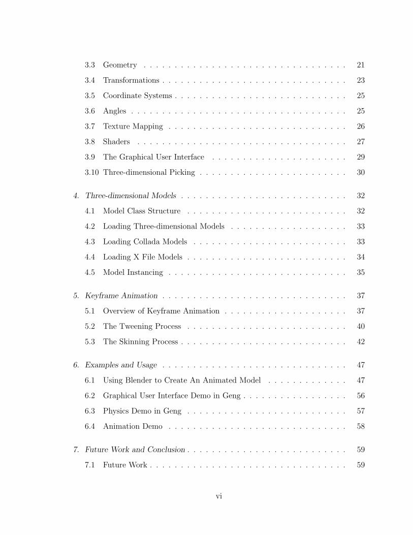
3.3 Geometry . . . . . . . . . . . . . . . . . . . . . . . . . . . . . . . . . 21
3.4 Transformations . . . . . . . . . . . . . . . . . . . . . . . . . . . . . . 23
3.5 Coordinate Systems . . . . . . . . . . . . . . . . . . . . . . . . . . . . 25
3.6 Angles . . . . . . . . . . . . . . . . . . . . . . . . . . . . . . . . . . . 25
3.7 Texture Mapping . . . . . . . . . . . . . . . . . . . . . . . . . . . . . 26
3.8 Shaders . . . . . . . . . . . . . . . . . . . . . . . . . . . . . . . . . . 27
3.9 The Graphical User Interface . . . . . . . . . . . . . . . . . . . . . . 29
3.10 Three-dimensional Picking . . . . . . . . . . . . . . . . . . . . . . . . 30
4. Three-dimensional Models . . . . . . . . . . . . . . . . . . . . . . . . . . . 32
4.1 Model Class Structure . . . . . . . . . . . . . . . . . . . . . . . . . . 32
4.2 Loading Three-dimensional Models . . . . . . . . . . . . . . . . . . . 33
4.3 Loading Collada Models . . . . . . . . . . . . . . . . . . . . . . . . . 33
4.4 Loading X File Models . . . . . . . . . . . . . . . . . . . . . . . . . . 34
4.5 Model Instancing . . . . . . . . . . . . . . . . . . . . . . . . . . . . . 35
5. Keyframe Animation . . . . . . . . . . . . . . . . . . . . . . . . . . . . . . 37
5.1 Overview of Keyframe Animation . . . . . . . . . . . . . . . . . . . . 37
5.2 The Tweening Process . . . . . . . . . . . . . . . . . . . . . . . . . . 40
5.3 The Skinning Process . . . . . . . . . . . . . . . . . . . . . . . . . . . 42
6. Examples and Usage . . . . . . . . . . . . . . . . . . . . . . . . . . . . . . 47
6.1 Using Blender to Create An Animated Model . . . . . . . . . . . . . 47
6.2 Graphical User Interface Demo in Geng . . . . . . . . . . . . . . . . . 56
6.3 Physics Demo in Geng . . . . . . . . . . . . . . . . . . . . . . . . . . 57
6.4 Animation Demo . . . . . . . . . . . . . . . . . . . . . . . . . . . . . 58
7. Future Work and Conclusion . . . . . . . . . . . . . . . . . . . . . . . . . . 59
7.1 Future Work . . . . . . . . . . . . . . . . . . . . . . . . . . . . . . . . 59
vi
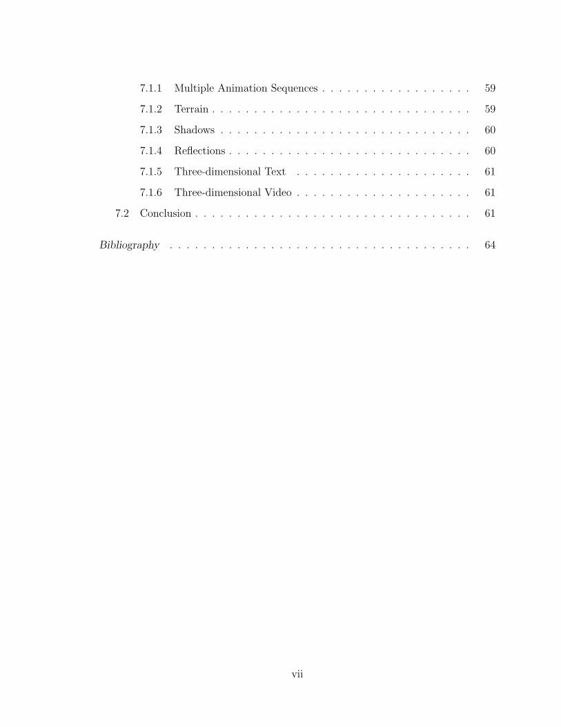
7.1.1 Multiple Animation Sequences . . . . . . . . . . . . . . . . . . 59
7.1.2 Terrain . . . . . . . . . . . . . . . . . . . . . . . . . . . . . . . 59
7.1.3 Shadows . . . . . . . . . . . . . . . . . . . . . . . . . . . . . . 60
7.1.4 Reflections . . . . . . . . . . . . . . . . . . . . . . . . . . . . . 60
7.1.5 Three-dimensional Text . . . . . . . . . . . . . . . . . . . . . 61
7.1.6 Three-dimensional Video . . . . . . . . . . . . . . . . . . . . . 61
7.2 Conclusion . . . . . . . . . . . . . . . . . . . . . . . . . . . . . . . . . 61
Bibliography . . . . . . . . . . . . . . . . . . . . . . . . . . . . . . . . . . . . 64
vii
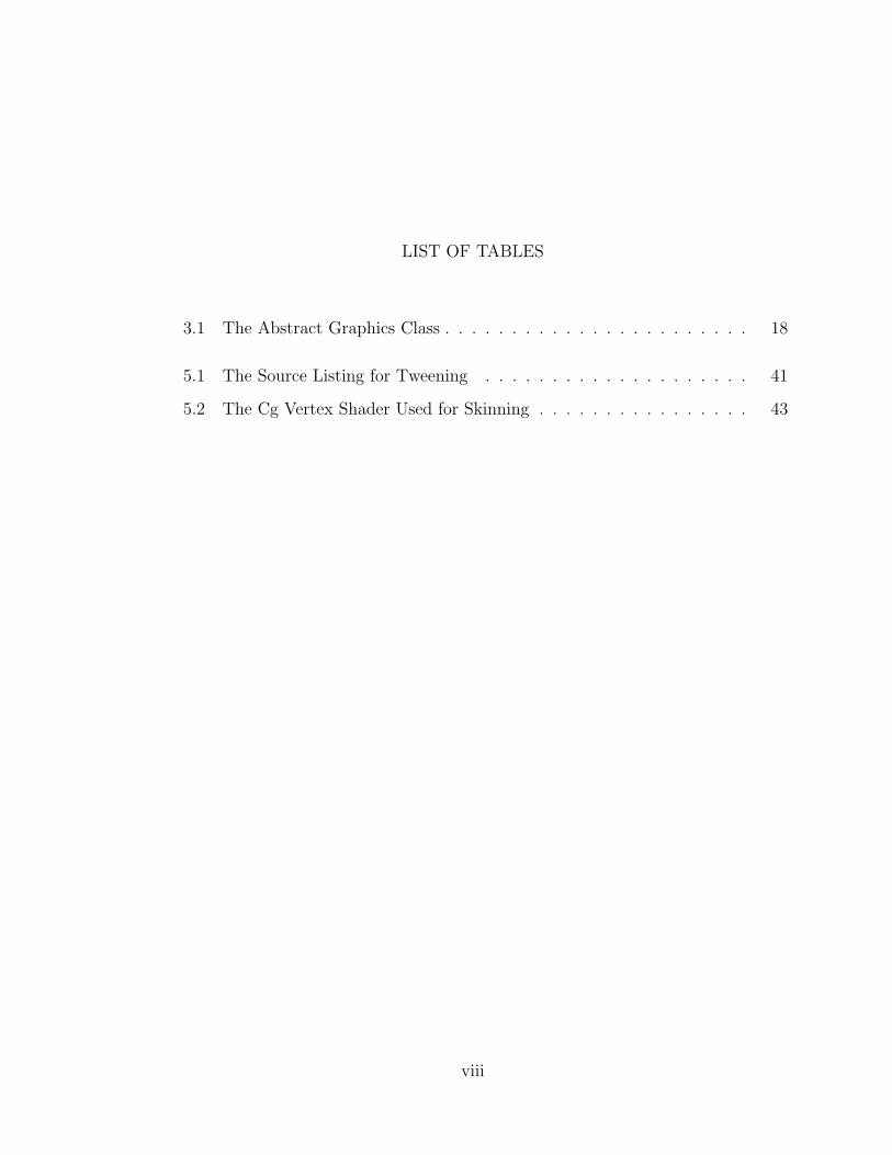
LIST OF TABLES
3.1 The Abstract Graphics Class . . . . . . . . . . . . . . . . . . . . . . . 18
5.1 The Source Listing for Tweening . . . . . . . . . . . . . . . . . . . . 41
5.2 The Cg Vertex Shader Used for Skinning . . . . . . . . . . . . . . . . 43
viii
LIST OF FIGURES
2.1 Rectangular Solid Drawn With Perspective Projection . . . . . . . . . 8
2.2 Rectangular Solid Drawn With Orthographic Projection . . . . . . . 9
2.3 The Graphics Pipeline . . . . . . . . . . . . . . . . . . . . . . . . . . 11
2.4 Shaded Rectangles Optical Illusion . . . . . . . . . . . . . . . . . . . 14
3.1 Geng Block Diagram . . . . . . . . . . . . . . . . . . . . . . . . . . . 16
3.2 Graphics Class Structure . . . . . . . . . . . . . . . . . . . . . . . . . 17
3.3 The Vertex Buffer and Index Buffer Class Structure . . . . . . . . . . 23
3.4 Texture Mapping Class Structure . . . . . . . . . . . . . . . . . . . . 27
3.5 Vertex Shader and Fragment Shader Class Structure . . . . . . . . . 28
3.6 The Graphical User Interface Class Structure . . . . . . . . . . . . . 30
4.1 The Model Class Structure . . . . . . . . . . . . . . . . . . . . . . . . 32
4.2 The Class Structure for Reading Collada Files . . . . . . . . . . . . . 34
4.3 The Class Structure for Reading X Files . . . . . . . . . . . . . . . . 35
4.4 Model Class Structure With SceneNode . . . . . . . . . . . . . . . . . 36
5.1 Distortion Effect When Rotating a Square . . . . . . . . . . . . . . . 38
5.2 Cosine Wave . . . . . . . . . . . . . . . . . . . . . . . . . . . . . . . . 38
5.3 Sine Wave . . . . . . . . . . . . . . . . . . . . . . . . . . . . . . . . . 39
5.4 The Animation Class Structure . . . . . . . . . . . . . . . . . . . . . 42
6.1 The Initial View In Blender . . . . . . . . . . . . . . . . . . . . . . . 48
6.2 Side View After Thinning the Cube . . . . . . . . . . . . . . . . . . . 50
ix
6.3 The Subdivide Button in Blender . . . . . . . . . . . . . . . . . . . . 51
6.4 The Robot Model in Blender . . . . . . . . . . . . . . . . . . . . . . . 52
6.5 Robot With First Bone Added . . . . . . . . . . . . . . . . . . . . . . 53
6.6 Robot With Parent And Child Bone . . . . . . . . . . . . . . . . . . 54
6.7 Blender With Skeleton . . . . . . . . . . . . . . . . . . . . . . . . . . 55
6.8 The Graphics Engine Demo Using Geng . . . . . . . . . . . . . . . . 57
6.9 Robots Chasing Each Other . . . . . . . . . . . . . . . . . . . . . . . 58
x
1. INTRODUCTION
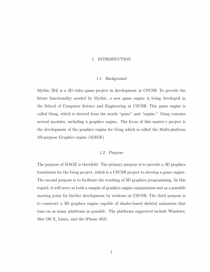
1.1 Background
Mythic [B4] is a 3D video game project in development at CSUSB. To provide the
future functionality needed by Mythic, a new game engine is being developed in
the School of Computer Science and Engineering at CSUSB. This game engine is
called Geng, which is derived from the words “game” and “engine.” Geng contains
several modules, including a graphics engine. The focus of this master’s project is
the development of the graphics engine for Geng which is called the Multi-platform
All-purpose Graphics engine (MAGE).
1.2 Purpose
The purpose of MAGE is threefold. The primary purpose is to provide a 3D graphics
foundation for the Geng project, which is a CSUSB project to develop a game engine.
The second purpose is to facilitate the teaching of 3D graphics programming. In this
regard, it will serve as both a sample of graphics engine organization and as a possible
starting point for further development by students at CSUSB. The third purpose is
to construct a 3D graphics engine capable of shader-based skeletal animation that
runs on as many platforms as possible. The platforms supported include Windows,
Mac OS X, Linux, and the iPhone 3GS.
1
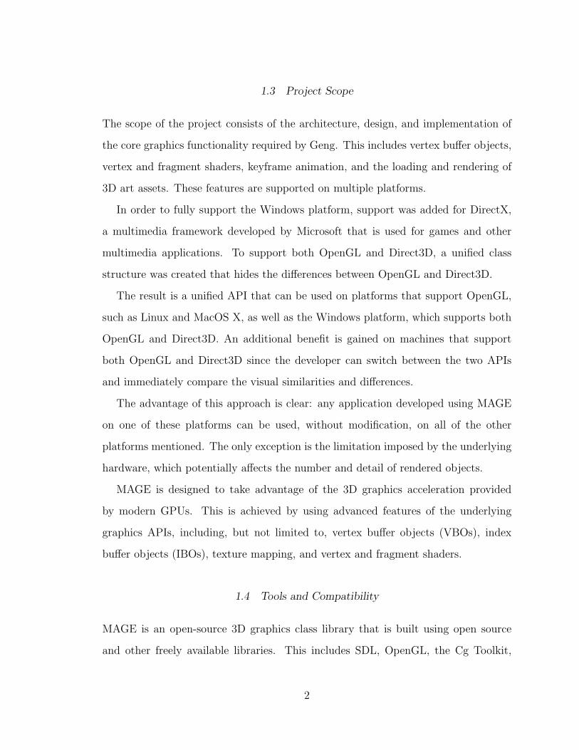
1.3 Project Scope
The scope of the project consists of the architecture, design, and implementation of
the core graphics functionality required by Geng. This includes vertex buffer objects,
vertex and fragment shaders, keyframe animation, and the loading and rendering of
3D art assets. These features are supported on multiple platforms.
In order to fully support the Windows platform, support was added for DirectX,
a multimedia framework developed by Microsoft that is used for games and other
multimedia applications. To support both OpenGL and Direct3D, a unified class
structure was created that hides the differences between OpenGL and Direct3D.
The result is a unified API that can be used on platforms that support OpenGL,
such as Linux and MacOS X, as well as the Windows platform, which supports both
OpenGL and Direct3D. An additional benefit is gained on machines that support
both OpenGL and Direct3D since the developer can switch between the two APIs
and immediately compare the visual similarities and differences.
The advantage of this approach is clear: any application developed using MAGE
on one of these platforms can be used, without modification, on all of the other
platforms mentioned. The only exception is the limitation imposed by the underlying
hardware, which potentially affects the number and detail of rendered objects.
MAGE is designed to take advantage of the 3D graphics acceleration provided
by modern GPUs. This is achieved by using advanced features of the underlying
graphics APIs, including, but not limited to, vertex buffer objects (VBOs), index
buffer objects (IBOs), texture mapping, and vertex and fragment shaders.
1.4 Tools and Compatibility
MAGE is an open-source 3D graphics class library that is built using open source
and other freely available libraries. This includes SDL, OpenGL, the Cg Toolkit,
2
ffmpeg, Bullet physics, and the DirectX SDK. It is written in the C++ language
and is primarily developed in the Windows XP platform using Visual Studio 2008.
Subversion (SVN) is used as the source control tool, and Tortoise is used as the SVN
client. Cygwin, a Windows port of the Unix command-line interface, is used as the
command-line interface.
1.5 Project Limitations
MAGE is designed to support multiple platforms. It can be built and run on Windows,
Mac OS X, Linux, and the iPhone 3GS. The minimum requirements for using MAGE
are DirectX 9 (for Windows only), OpenGL version 2.0, the Cg Toolkit version 2.0,
and a graphics card that supports Shader Model 2.0. For the iPhone, the Cg shader
language is not available, so the only shading language supported is GLSL. The iPhone
is also limited in the use of OpenGL since it only supports OpenGL ES. OpenGL ES
is an OpenGL implementation designed for embedded systems. Other limitations of
the iPhone are hardware related, including a relatively small amount of memory, a
small screen size, and the lack of a physical keyboard.
1.6 Definitions, Acronyms, and Abbreviations
• Blending: The process of combining multiple images in some proportion to create
a single image. This is related to the process of transparency.
• Bump Mapping: Adds texture to images by performing lighting calculations with
respect to the normals assigned to vertices. Creates the illusion of a bumped
surface by causing perturbations in the surface normals.
• Cg Shading Language: Cg is a language for writing vertex and fragment shaders
created by Nvidia.
3
• Direct3D: A 3D API developed by Microsoft designed for use on Windows ma-
chines. Direct3D is a module within DirectX.
• DirectX: A set of modules that serves as a software development kit for creating
multimedia applications on Windows machines. It was originally called the Game
SDK and was motivated by the need of game programmers to bring cutting edge
graphics to early Windows releases.
• Face Culling: When drawing a polygon, only one of the faces can be seen. The
other face can be culled, which means it is not drawn.
• Geng: A game engine being developed at CSUSB to support Mythic.
• GLSL: The OpenGL shading language.
• Glow Effect: A glow is a bright diffuse light that emanates from an object. Where
the object has well-defined boundaries, the glow has a fuzzy boundary. This can
be achieved by blending a special glowing image with the original image.
• Graphics Engine: Provides support for graphics functionality needed by an ap-
plication. Also called a graphics library or a graphics API.
• GPU: Graphics Processing Unit. Also called a Graphics Card. Previously called
a Graphics Accelerator, modern GPUs are also used for scientific computation
and in some cases are designed solely for scientific computation.
• HUD: Stands for heads-up-display. Pixels that are always in front of other pixels
and are transformed with the camera. That is, the HUD is effectively part of
the camera. May include GUI objects.
• Keyframe Animation: A skeletal structure is associated with vertices. Each bone
is a transformation, and each vertex is controlled by a set of bones. Each frame
of animation is a specification of each bones transformation for that frame. The
4

bone transformations are hierarchical in nature, so transformations are releative
to the parents transformation. The two basic parts of the process are called
tweening and skinning. Tweening is done on the CPU, and skinning is done in
the vertex shader on the GPU.
• Khronos Group: A non-profit consortium that manages OpenGL and other tech-
nologies, primarily associated with 3D graphics technologies.
• MAGE: Multi-platform All-purpose Graphics Engine.
• Mesh: A collection of polygons connected together. Commonly, a mesh will
consist of connected quads forming a rectangular pattern.
• Mythic: A 3D game being developed at CSUSB.
• Normal: A vector that is conceptually orthogonal to a polygon (for the purposes
of 3D graphics, a normal is not required to be perpendicular to a surface). Used
in lighting calculations to determine how much light is reflected by a surface.
• Linear Interpolation: Intermediate positions between points are calculated based
on a linear function.
• Object Culling: Objects that are not in the view volume or are obstructed by
other objects are not drawn.
• OpenGL ES 2.0: An OpenGL specification designed for embedded systems, such
as the iPhone 3GS. It is a streamlined version of OpenGL that provides advanced
features such as vertex buffer objects, frame buffer objects, and shader support.
• Particle Effects: Individual vertices, or small polygons, are controlled indepen-
dently to simulate effects such as dust or smoke.
• Shader: A program that is compiled and downloaded to a graphics card. There
are two main types of shaders: vertex and fragment. Vertex shaders manipu-
5
late the vertices as they come through the graphics pipeline. Fragment shaders
manipulate pixel properties as pixels are processed in the graphics pipeline.
• Stencil buffer: A buffer that contains a value for each pixel. The value indicates
that the pixel should be drawn or ignored.
• Texture Mapping: The mapping of a 2D image onto a 3D object.
• Transparency: Simulating the effect of being able to see a background object
through a foreground object.
• Vertex Buffer Object: A container of vertices that represent the geometry of one
or more 3D objects. Usually used with an index buffer that defines the polygons
that comprise the 3D objects.
• Z-buffer: A data buffer that contains a depth value for each pixel. If the depth
of an incoming pixel is less than that in the buffer, then it is drawn over the
previous pixel, otherwise it is ignored.
6
2. AN OVERVIEW OF THREE-DIMENSIONAL GRAPHICS
In order to set the stage for the following technical discussion of MAGE, an overview
of three-dimensional (3D) graphics programming is presented.
2.1 Description of Three-dimensional Graphics
Current video displays are flat. That is, the images that the user sees are displayed
on a two-dimensional surface, or screen. The challenge for three-dimensional (3D)
graphics programmers, then, is to realistically display a 3D scene on a 2D surface.
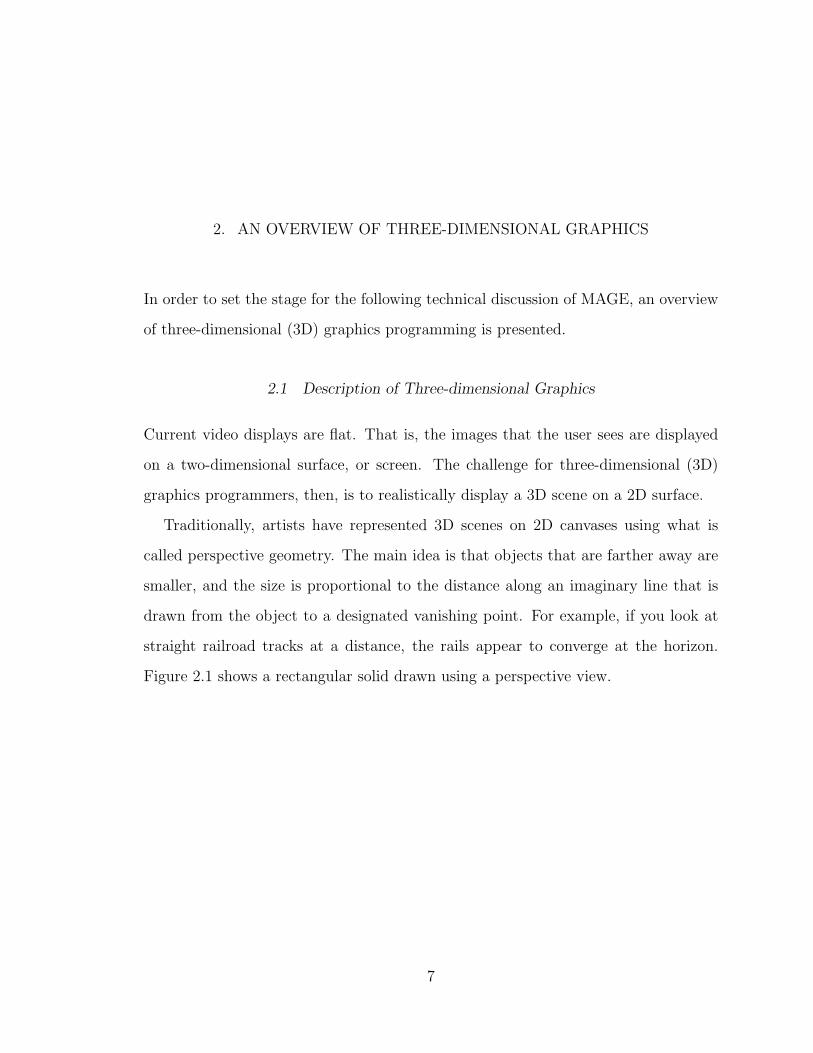
Traditionally, artists have represented 3D scenes on 2D canvases using what is
called perspective geometry. The main idea is that objects that are farther away are
smaller, and the size is proportional to the distance along an imaginary line that is
drawn from the object to a designated vanishing point. For example, if you look at
straight railroad tracks at a distance, the rails appear to converge at the horizon.
Figure 2.1 shows a rectangular solid drawn using a perspective view.
7

Fig. 2.1: Rectangular Solid Drawn With Perspective Projection
Another geometric method for displaying objects in a scene is called the ortho-
graphic projection. In this method, lines are drawn the same length without regard
to the distance from the viewer. Figure 2.2 shows a rectangular solid drawn using
orthographic projection. This projection does not present a realistic rendering of
3D, and is not generally used for displaying 3D virtual worlds. It is useful when the
emphasis is not realism, but accuracy in angles and length, such as 3D architecture.
8

Fig. 2.2: Rectangular Solid Drawn With Orthographic Projection
The three-dimensional (3D) graphics programmer is concerned with rendering ob-
jects in a 3D virtual world. The objects to be rendered are represented internally
by vertices in a 3D Euclidean space. The vertices have three components, sometimes
called width, height, and depth, and can be represented by an ordered triple, such as
(x, y, z). Although the designation is arbitrary, x usually represents the horizontal
position, y represents the vertical position, and z represents the depth. After the
final positions for all of the vertices are determined, a perspective calculation is per-
9
formed to realistically display the vertices on a 2D space. The perception of depth is
achieved by performing what is called a perspective projection on the vertices. Per-
spective projection is a mathematical technique that uses a linear transformation to
project 3D geometry onto flat surfaces.
Besides the perception of depth, there are other considerations that a 3D graph-
ics programmer must deal with. If the viewpoint is changed, the geometry in the
scene needs to be transformed accordingly. Another consideration is an object that
obstructs another object. For example, an object in the foreground may obstruct
the view of an object in the background. To render the objects correctly, a depth
buffer is used to determine which vertices can be seen by the viewer. To render the
objects efficiently, the vertices that are obstructed can be culled. This means they are
removed from the scene before the scene is rendered.
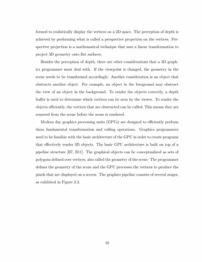
Modern day graphics processing units (GPUs) are designed to efficiently perform
these fundamental transformation and culling operations. Graphics programmers
need to be familiar with the basic architecture of the GPU in order to create programs
that effectively render 3D objects. The basic GPU architecture is built on top of a
pipeline structure [B7, B11]. The graphical objects can be conceptualized as sets of
polygons defined over vertices, also called the geometry of the scene. The programmer
defines the geometry of the scene and the GPU processes the vertices to produce the
pixels that are displayed on a screen. The graphics pipeline consists of several stages,
as exhibited in Figure 2.3.
10
Fig. 2.3: The Graphics Pipeline
The programmer provides the vertices in containers called vertex buffers. In order
to prevent the duplication of vertices due to the fact that polygons can share vertices,
an index buffer can also be used. The index buffer is a container of references to
vertices in the vertex buffer.
The graphics API developed for this project requires the use of vertex buffers to
represent the vertices, and the use of index buffers to define the triangles for models
in the scene. One reason is the efficiency gained, both in space and in time. The
other reason is that some systems are restrictive in how the vertices are represented
and the geometry is presented. For example, Direct3D allows only vertex buffers to
represent vertices, and OpenGL ES allows only triangles to represent the 3D geometry
(OpenGL ES also supports individual points and lines). On the other hand, general
OpenGL allows vertices to be set on an individual basis and geometry to be defined
by more general polygons.
Another fundamental concept in 3D programming is that of texture mapping. Tex-
ture mapping is heavily used in modern 3D applications and is one of the fundamental
operations that GPUs support. Texture mapping is the process of applying 2D im-
ages, such as digitized pictures, to the polygons of 3D objects. Texture mapping is
generally a very efficient way to add realistic patterns of colors to 3D objects, and is
used in many advanced 3D graphical techniques, such as bump mapping.
The last topic discussed in the overview of 3D graphics is that of vertex and frag-
ment shaders. Figure 4 shows the different stages of the graphics pipeline. Modern
graphics cards generally allow two of these stages to be programmed by the appli-
11
cation developer. One of these stages is the vertex processor, and the other is the
pixel processor. Essentially the vertex processor determines the final positions of the
vertices, and the pixel processor determines the final color of the pixels that are dis-
played on the screen. A vertex processing program is called a vertex shader, and a
pixel processing program is called a pixel shader, or alternatively, a fragment shader.
Utilizing the processing power of the GPU, many effects can be achieved, such as wa-
ter waves, particle effects, and customized lighting effects, that would not be practical
for a real-time application otherwise.
2.2 Real-time Interactive Three-dimensional Graphics
MAGE was designed to be used for the creation of real-time three-dimensional (3D)
graphics applications. Real-time applications include, but are not limited to, com-
puter games, scientific simulations, 3D presentation applications, and educational
software. In this type of application, graphical objects are updated and rendered on
a frame-by-frame basis, at a frame rate that is sufficiently high to give the illusion
of smooth motion. This is the same principle that gives motion pictures the illusion
of motion, even though a motion picture consists of fixed images. These images are
shown in sequence, usually at the rate of 24 per second. To achieve this smooth-
motion effect for computer games, generally a higher frame rate is needed, such as
50 frames per second, or higher. The higher frame rate for games is needed due to
the existence of graphical artifacts, or anomalies, that are perceived by the human
eye as a result of the digital nature of computer displays and the level of detail of
rendered objects. It is also important to match the frame rate with the refresh rate
of the computer monitor. If a scene is updated during the screen refresh process,
a graphical artifact known as tearing may result. To put the challenge of creating
real-time graphical applications into perspective, consider that, in order to achieve 50
frames per second, all of the computations required to manipulate all of the objects
12

in a scene must be done within 20 milliseconds. If you play a modern game with this
in mind, you can see how amazing modern games are as a technical achievement.
MAGE is also designed to support interactions with the user. This is needed in a
computer game, and is provided by supporting both 2D and 3D picking. This means
that user can use a mouse to select 3D objects in the scene. Two dimensional overlays
are also supported, for which icons serve as examples.
2.3 The Illusion of Three-dimensions
The term ”three-dimensional” can have different meanings. For three-dimensional
(3D) movies, special glasses are required to correctly show the slight difference in
images that the left and right eye are viewing, called parallax. This could be called
true 3D, since it simulates true depth of field that the eyes see in the real world. But
this is not the 3D representation that is usual used for 3D computer applications.
For 3D computer applications and games, 3D means that the underlying geometry
is represented using three directions, or coordinates, even though the final image is
displayed on a standard two-dimensional display. That is, it is not true 3D, but
nevertheless our minds perceive it as being 3D.
So how is it, then, that we can perceive a three-dimensional scene displayed in two
dimensions? There are many articles and books that deal with this topic, which is
usually under the moniker of optical illusions. It is the same mechanisms that allows
us to perceive three dimensions when, in actuality, only two dimensions are rendered.
A simple example of an optical illusion is shown in Figure 2.4. The rectangle that
appears to be farther away also appears to be larger than the other rectangle, but
they are the same size. Some more examples of optical illusions are presented in [B3].
13
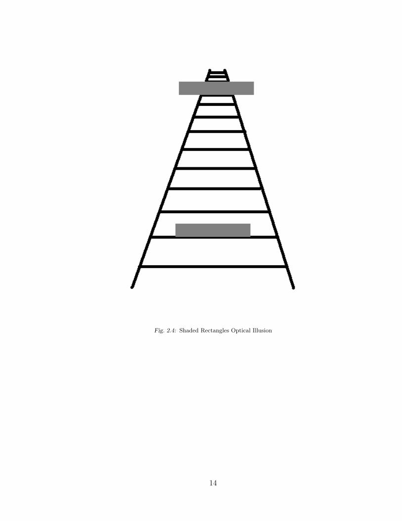
Fig. 2.4: Shaded Rectangles Optical Illusion
14
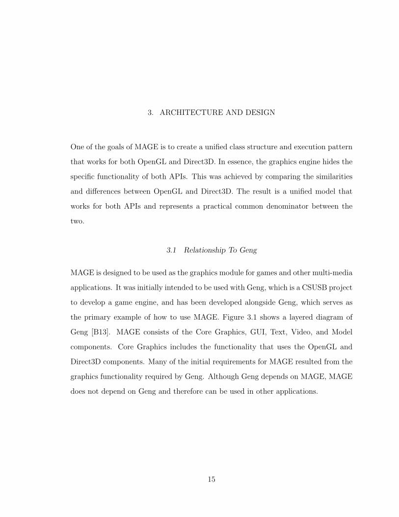
3. ARCHITECTURE AND DESIGN
One of the goals of MAGE is to create a unified class structure and execution pattern
that works for both OpenGL and Direct3D. In essence, the graphics engine hides the
specific functionality of both APIs. This was achieved by comparing the similarities
and differences between OpenGL and Direct3D. The result is a unified model that
works for both APIs and represents a practical common denominator between the
two.
3.1 Relationship To Geng
MAGE is designed to be used as the graphics module for games and other multi-media
applications. It was initially intended to be used with Geng, which is a CSUSB project
to develop a game engine, and has been developed alongside Geng, which serves as
the primary example of how to use MAGE. Figure 3.1 shows a layered diagram of
Geng [B13]. MAGE consists of the Core Graphics, GUI, Text, Video, and Model
components. Core Graphics includes the functionality that uses the OpenGL and
Direct3D components. Many of the initial requirements for MAGE resulted from the
graphics functionality required by Geng. Although Geng depends on MAGE, MAGE
does not depend on Geng and therefore can be used in other applications.
15

Fig. 3.1: Geng Block Diagram
3.2 The Unified Application Programming Interface
The unified application programming interface (API) is encapsulated in an interface
called Graphics. This interface is implemented for OpenGL using a concrete class
called GLGraphics, and for Direct3D using a concrete class called D3DGraphics. A
class diagram for the Graphics class can be seen in Figure 3.2.
16
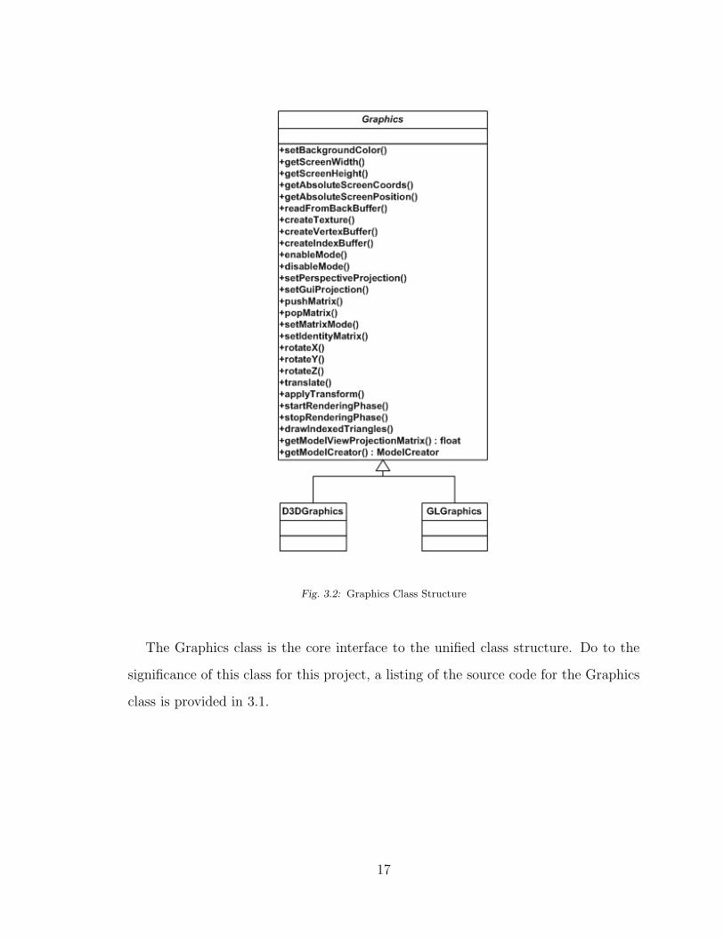
Fig. 3.2: Graphics Class Structure
The Graphics class is the core interface to the unified class structure. Do to the
significance of this class for this project, a listing of the source code for the Graphics
class is provided in 3.1.
17
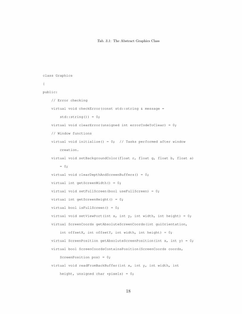
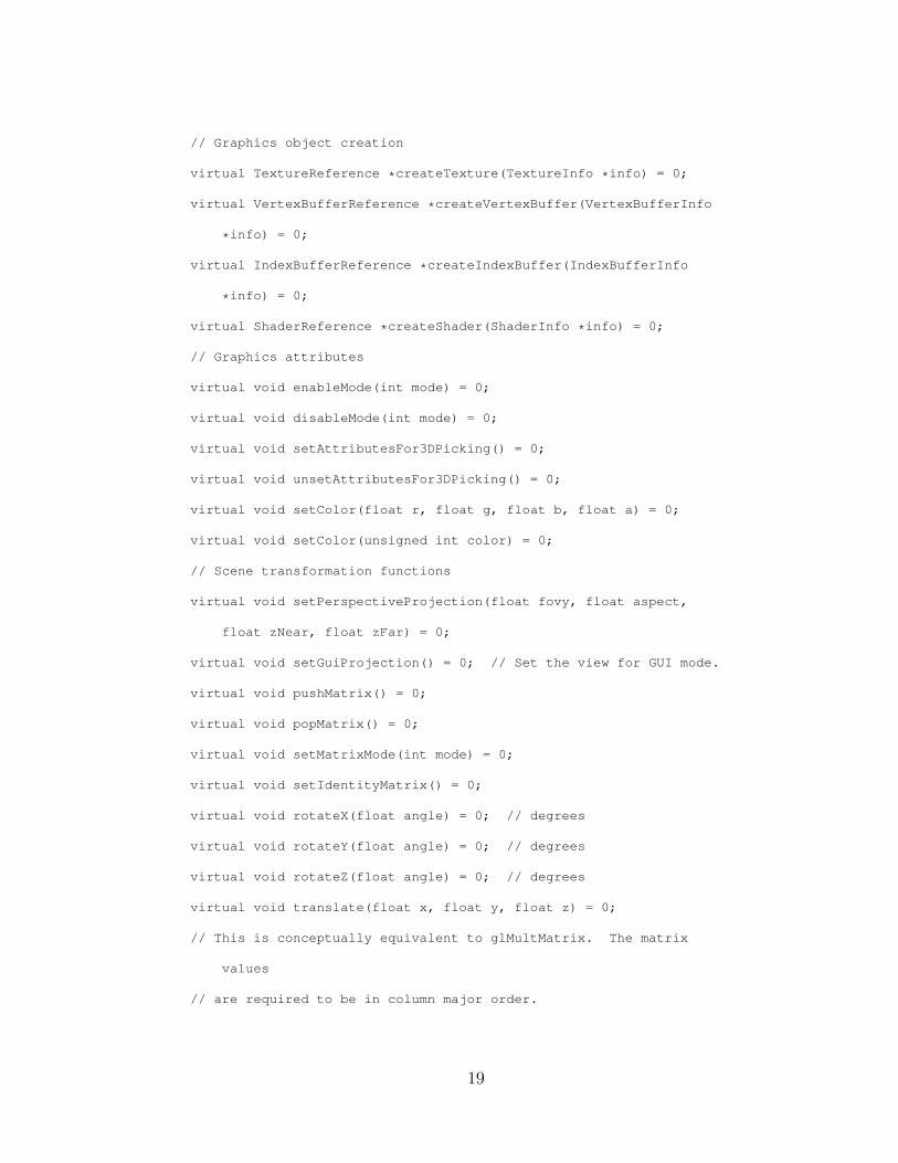
Tab. 3.1: The Abstract Graphics Class
class Graphics
{
public:
// Error checking
virtual void checkError(const std::string & message =
std::string()) = 0;
virtual void clearError(unsigned int errorCodeToClear) = 0;
// Window functions
virtual void initialize() = 0; // Tasks performed after window
creation.
virtual void setBackgroundColor(float r, float g, float b, float a)
= 0;
virtual void clearDepthAndScreenBuffers() = 0;
virtual int getScreenWidth() = 0;
virtual void setFullScreen(bool useFullScreen) = 0;
virtual int getScreenHeight() = 0;
virtual bool isFullScreen() = 0;
virtual void setViewPort(int x, int y, int width, int height) = 0;
virtual ScreenCoords getAbsoluteScreenCoords(int guiOrientation,
int offsetX, int offsetY, int width, int height) = 0;
virtual ScreenPosition getAbsoluteScreenPosition(int x, int y) = 0;
virtual bool ScreenCoordsContainsPosition(ScreenCoords coords,
ScreenPosition pos) = 0;
virtual void readFromBackBuffer(int x, int y, int width, int
height, unsigned char *pixels) = 0;
18
// Graphics object creation
virtual TextureReference *createTexture(TextureInfo *info) = 0;
virtual VertexBufferReference *createVertexBuffer(VertexBufferInfo
*info) = 0;
virtual IndexBufferReference *createIndexBuffer(IndexBufferInfo
*info) = 0;
virtual ShaderReference *createShader(ShaderInfo *info) = 0;
// Graphics attributes
virtual void enableMode(int mode) = 0;
virtual void disableMode(int mode) = 0;
virtual void setAttributesFor3DPicking() = 0;
virtual void unsetAttributesFor3DPicking() = 0;
virtual void setColor(float r, float g, float b, float a) = 0;
virtual void setColor(unsigned int color) = 0;
// Scene transformation functions
virtual void setPerspectiveProjection(float fovy, float aspect,
float zNear, float zFar) = 0;
virtual void setGuiProjection() = 0; // Set the view for GUI mode.
virtual void pushMatrix() = 0;
virtual void popMatrix() = 0;
virtual void setMatrixMode(int mode) = 0;
virtual void setIdentityMatrix() = 0;
virtual void rotateX(float angle) = 0; // degrees
virtual void rotateY(float angle) = 0; // degrees
virtual void rotateZ(float angle) = 0; // degrees
virtual void translate(float x, float y, float z) = 0;
// This is conceptually equivalent to glMultMatrix. The matrix
values
// are required to be in column major order.
19
// Use array of floats to maintain independence from a specific
math library
virtual void applyTransform(float matrix[16]) = 0;
// Rendering functions
virtual void startRenderingPhase() = 0; // Call this before
rendering graphics objects.
virtual void stopRenderingPhase() = 0; // Call this when finished
rendering graphics objects.
virtual void drawIndexedTriangles(int count, int startIndex) = 0;
// Draws from currently active vertex and index buffers
virtual void swapBuffers() = 0;
// Misc
virtual float *getModelViewProjectionMatrix() = 0; // row-major
format
virtual bool usingDirect3D() = 0;
virtual void bindOpenGLExtensions() = 0;
// OpenGL and Direct3D have different creators due to some
// underlying differences in vertex formats.
virtual ModelCreator *getModelCreator() = 0;
virtual GuiImageCreator *getGuiImageCreator() = 0;
virtual FontGeometry *createFontGeometry() = 0;
virtual void setShaderIsActive(bool value) = 0;
enum {
ALPHA_TRANSPARENCY,
CULLING,
PROJECTION,
MODELVIEW,
TEXTURE_2D,
DEPTH_TEST,
20
ALPHA_TEST,
BLEND,
LIGHTING,
WIREFRAME
};
};
The following sections will discuss the details of the various features provided by
the unified graphics API.
3.3 Geometry
The core functionality of a 3D graphics engine is the handling of 3D geometry and
the transformations of the geometry. The geometry consists of vertices and geometric
primitives defined using the vertices. The primitives include points, lines, and poly-
gons. Although general polygons are supported for both OpenGL and Direct3D, the
use of triangles is usually considered more efficient. For this reason, and also for the
sake of simplicity, MAGE only supports triangles.
OpenGL and Direct3D use different methods for specifying the geometry. OpenGL
is more versatile than Direct3D in this regard. OpenGL allows the vertices to be
specified individually or as arrays of vertices. Direct3D only allows vertices to be
specified as a collection of vertices called a vertex buffer. Later versions of OpenGL
also support the use of vertex buffers and are called vertex buffer objects, or VBOs.
To take advantage of the common support for VBOs, MAGE supports VBOs. Index
buffers can also be used in conjunction with VBOs.
Index buffers contain indicies, or references, to the vertices in a vertex buffer.
The main advantage of using index buffers is to avoid the duplication of vertices for
triangles that share common vertices with other triangles. MAGE requires the use of
index buffers for specifying the triangles.
21
In MAGE, vertex buffers are represented by a VertexBufferReference object, and
index buffers are represented by an IndexBufferReference object. Both of these classes
are abstract, and have OpenGL and Direct3D concrete classes called, respectively,
GLVertexBufferReference, GLIndexBufferReference, D3DVertexBufferReference, and
D3DIndexBufferReference. In order to use a vertex buffer, a VertexBufferInfo object
must be created. This object defines the properties of the vertex buffer. The Graphics
class has a factory method called createVertexBuffer that creates a VertexBufferRef-
erence. The same pattern is used for creating an IndexBufferReference. First, an
IndexBufferInfo object is created, then a factory method in Graphics called createIn-
dexBuffer is called to create the IndexBufferReference. When a model is drawn, its
vertex buffer and index buffer are activated, and these objects are deactivated after
the drawing is complete. Figure 3.3 shows the structure of the classes related to
vertex buffer objects.
22
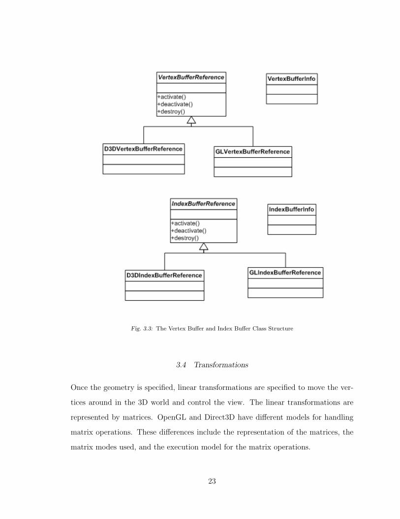
Fig. 3.3: The Vertex Buffer and Index Buffer Class Structure
3.4 Transformations
Once the geometry is specified, linear transformations are specified to move the ver-
tices around in the 3D world and control the view. The linear transformations are
represented by matrices. OpenGL and Direct3D have different models for handling
matrix operations. These differences include the representation of the matrices, the
matrix modes used, and the execution model for the matrix operations.
23

OpenGL stores matrix values using what is called column-major order. Direct3D
uses row-major order. For multiplication, OpenGL multiplies the vertex on the right,
and Direct3D multiplies the vertex on the left. This difference is actually not a
problem to deal with since the reverse order of the operations is offset by the matrix
order.
The matrix modes used by OpenGL and Direct3D are slightly different. The
primary matrix modes used in OpenGL are the projection mode and model-view
mode. The model-view matrix moves vertices in the virtual world. Since vertex
movement and camera movement are relative to each other, OpenGL uses a combines
the model matrix and the view matrix. For example, moving the object forward
is equivalent to moving the camera back. Direct3D, on the other hand, uses three
primary matrix modes: the projection matrix, the world matrix, and the view matrix.
The projection matrix is common to both APIs. But instead of combining the model
and the view matrix, Direct3D uses separate model and view matrices. This difference
has an affect on the execution models of the APIs.
OpenGL uses a matrix stack to keep track of the current matrix for both the
projection matrix and the model-view matrix. The concept of a matrix stack is closely
related to the combined model-view matrix. When a scene consists of multiple 3D
objects that move independently of each other, each object will be associated with
a model matrix. But there will still be only a single camera, so only a single view
matrix operation is required. The solution to this is to save the current matrix state
before applying a transformation to a specific model, and then restoring the matrix
state after the transformation is applied. A stack can be used for saving and restoring
the matrix state, and this is the reason the OpenGL execution model uses a matrix
stack. Direct3D, on the other hand, does not need a matrix stack. Each model can be
associated with its own transformation matrix, and a single matrix is used to specify
the position and orientation of the camera, which is shared by all of the models.
24
MAGE uses the OpenGL paradigm with respect to the matrix stack. This is
ultimately an arbitrary decision, but resulted from the need to convert OpenGL code
into a common framework. Therefore the graphics engine implements a matrix stack
explicitly when Direct3D is the targeted lower-level API (since Direct3D does not
provide a matrix stack).
3.5 Coordinate Systems
It is usually stated that OpenGL uses a right-handed coordinate system and Direct3D
uses a left-handed coordinate system. This is true, but only with respect to the
default behavior when using certain common utility functions. The handedness of
the coordinate system is ultimately determined by the projection matrix that is used.
The default projection matrix for OpenGL results in a right-handed system. Direct3D
offers utility functions for both a left-handed projection matrix and a right-handed
projection matrix. For both OpenGL and Direct3D, it is quite simple to specify
a custom projection matrix. Nevertheless, MAGE uses a right-handed coordinate
system as the default.
3.6 Angles
For mathematical functions that perform rotations, or otherwise operate on angles,
OpenGL uses degrees. Direct3D, on the other hand, uses radians. Many common
math libraries also use radians. Although an arbitrary decision, MAGE uses degrees.
As with the execution model for transformations, this is a result of moving existing
OpenGL code into a common framework.
25

3.7 Texture Mapping
Texture mapping is the process of applying a standard 2D image to a 3D object, and
is one of the primary techniques used to add realism to a real-time interactive 3D
application. Therefore, texture mapping is one of the fundamental operations per-
formed by specialized graphics cards. Since OpenGL and Direct3D are both designed
to support the use of modern graphics cards for 3D acceleration, it seems plausible
that there may be a similar design pattern between the two APIs. Indeed this is the
case. The implementation developed for this project represents one possibility for a
unified approach to texture mapping.
To use texture mapping in OpenGL, a texture object is created with arguments
indicating the properties of the texture. OpenGL returns an integer that represents
the ID of the texture object. When a graphical object that uses the texture is to
be drawn, the texture object is activated using its ID. After the object is drawn, the
texture object is deactivated.
The texture mapping process is very similar when using Direct3D, although the
underlying implementation details are quite different. Instead of an ID, the Direct3D
library returns a pointer to a texture object. When the graphical object that uses the
texture is be drawn, the texture is activated using the pointer to the texture object.
After the object is drawn, the texture can be deactivated.
A design pattern was created for MAGE that accommodates the common func-
tionality used by OpenGL and Direct3D. This can be seen in Figure 3.4. In order
to create a texture object, a TextureInfo object is created. A TextureInfo object
encapsulates the description and properties of the texture and how it will be applied.
A factory method in the Graphics object creates a TextureReference object from the
TextureInfo object.
26
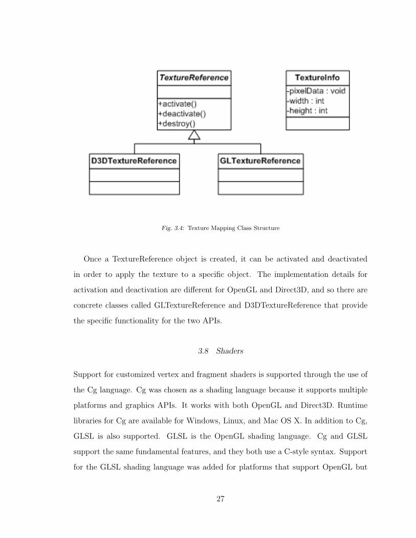
Fig. 3.4: Texture Mapping Class Structure
Once a TextureReference object is created, it can be activated and deactivated
in order to apply the texture to a specific object. The implementation details for
activation and deactivation are different for OpenGL and Direct3D, and so there are
concrete classes called GLTextureReference and D3DTextureReference that provide
the specific functionality for the two APIs.
3.8 Shaders
Support for customized vertex and fragment shaders is supported through the use of
the Cg language. Cg was chosen as a shading language because it supports multiple
platforms and graphics APIs. It works with both OpenGL and Direct3D. Runtime
libraries for Cg are available for Windows, Linux, and Mac OS X. In addition to Cg,
GLSL is also supported. GLSL is the OpenGL shading language. Cg and GLSL
support the same fundamental features, and they both use a C-style syntax. Support
for the GLSL shading language was added for platforms that support OpenGL but
27
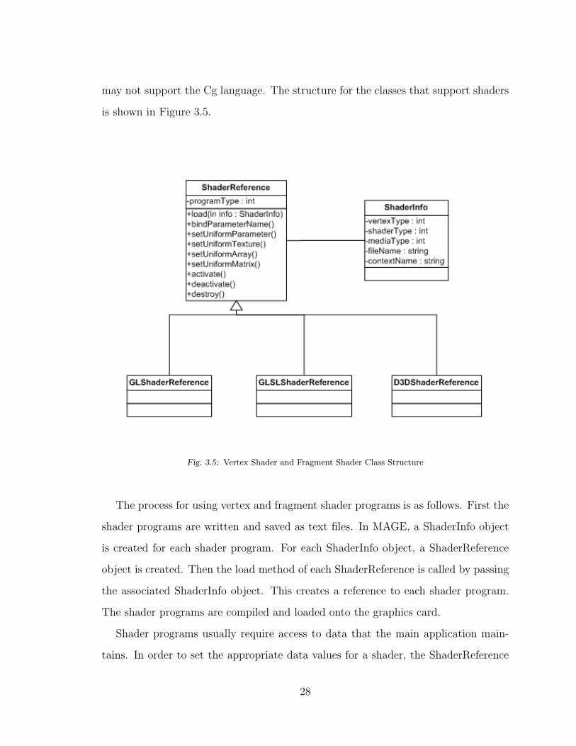
may not support the Cg language. The structure for the classes that support shaders
is shown in Figure 3.5.
Fig. 3.5: Vertex Shader and Fragment Shader Class Structure
The process for using vertex and fragment shader programs is as follows. First the
shader programs are written and saved as text files. In MAGE, a ShaderInfo object
is created for each shader program. For each ShaderInfo object, a ShaderReference
object is created. Then the load method of each ShaderReference is called by passing
the associated ShaderInfo object. This creates a reference to each shader program.
The shader programs are compiled and loaded onto the graphics card.
Shader programs usually require access to data that the main application main-
tains. In order to set the appropriate data values for a shader, the ShaderReference
28
methods setUniformParameter, setUniformTexture, setUniformArray, and setUnifor-
mMatrix can be called. The names of the data values used must be bound to the
shader program before it is used by calling the bindParameterName method.
When a shader program is used to render a model, the corresponding Shader-
Reference object is activated. When the rendering of the model is complete, the
corresponding ShaderReference object is deactivated. When a shader program is no
longer needed, the corresponding ShaderReference object is destroyed.
3.9 The Graphical User Interface
A graphical user interface generally consists of buttons, text input controls, combo
boxes, and other graphical controls that a user operates on using a mouse or other
pointing device. In a 3D application, where the user also interacts with 3D objects and
can manipulate the 3D scene, the entire application can be thought of as a graphical
user interface. The distinction can be made between the 2D controls and the 3D
scene by referring to the collection of 2D controls simply as the GUI. The elements in
the GUI move with the camera and are always displayed in front of other objects in
the scene, i.e. they are fixed with respect to the view. The GUI can also be referred
to as the HUD, for heads-up-display, and the individual elements of the GUI can be
referred to as overlay elements, since they overlay the objects in the 3D scene. The
elements in the GUI are subclasses of the GuiOverlay class. They include GuiText,
GuiImage, and GuiVideo. The class structure of the GUI in shown in Figure 3.6.
29
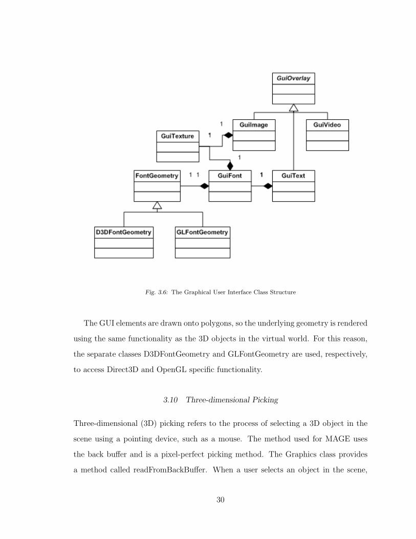
Fig. 3.6: The Graphical User Interface Class Structure
The GUI elements are drawn onto polygons, so the underlying geometry is rendered
using the same functionality as the 3D objects in the virtual world. For this reason,
the separate classes D3DFontGeometry and GLFontGeometry are used, respectively,
to access Direct3D and OpenGL specific functionality.
3.10 Three-dimensional Picking
Three-dimensional (3D) picking refers to the process of selecting a 3D object in the
scene using a pointing device, such as a mouse. The method used for MAGE uses
the back buffer and is a pixel-perfect picking method. The Graphics class provides
a method called readFromBackBuffer. When a user selects an object in the scene,
30

each object is given a unique color and drawn to the back buffer. This image is not
displayed on the screen. Instead, we look at the position selected, get the color at
that position, and find the object that was drawn with that color.
31
4. THREE-DIMENSIONAL MODELS
4.1 Model Class Structure
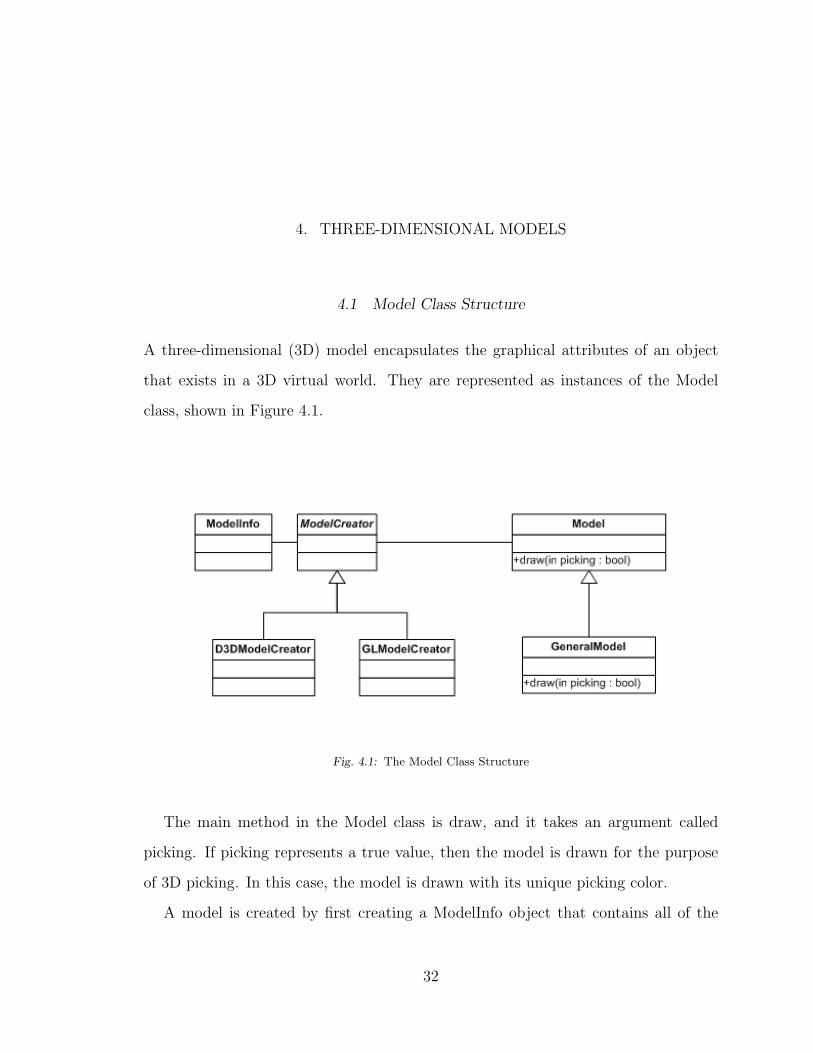
A three-dimensional (3D) model encapsulates the graphical attributes of an object
that exists in a 3D virtual world. They are represented as instances of the Model
class, shown in Figure 4.1.
Fig. 4.1: The Model Class Structure
The main method in the Model class is draw, and it takes an argument called
picking. If picking represents a true value, then the model is drawn for the purpose
of 3D picking. In this case, the model is drawn with its unique picking color.
A model is created by first creating a ModelInfo object that contains all of the
32

information needed to describe the model. Then the method createModel in the
Graphics concrete class is used to create a Model object from the ModelInfo object.
Due to the underlying differences in the vertex structures for OpenGL and Direct3D,
each lower level API has its own class. For OpenGL there is the GLModelCreator,
and for Direct3D, there is the D3DModelCreator.
GeneralModel is a special subclass of Model that supports animation and texture
mapping using Cg shaders. Depending on whether the model has a texture defined
for it, or whether or not it has an animation sequence, GeneralModel will choose the
appropriate shaders to correctly render the model.
4.2 Loading Three-dimensional Models
One of the major challenges of three-dimensional (3D) graphics programming is the
creation and integration of content. The content consists of 3D art assets that are
displayed in the scene. Generally, external programs are used to create the art assets,
including 3D models, which are then exported into an intermediary file format, and
eventually imported into the 3D graphics application. One such file format is called
Collada. Blender, a free 3D model creation tool, can be used to create 3D models
and export them to a Collada file. Another file format that is often used is the X file
format, which is also supported by this graphics engine.
4.3 Loading Collada Models
For this graphics engine, a simple XML file reader is used to read Collada files.
Currently, only static models consisting of a single mesh are supported. Figure 4.2
shows the class structure for the loading of a 3D model from a Collada file. This class
structure represents the nodes In the Collada file that are relevant to storing a single
mesh object.
33
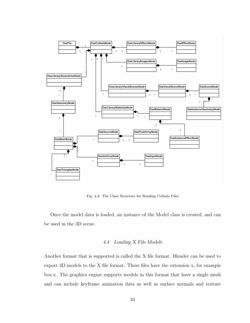
Fig. 4.2: The Class Structure for Reading Collada Files
Once the model data is loaded, an instance of the Model class is created, and can
be used in the 3D scene.
4.4 Loading X File Models
Another format that is supported is called the X file format. Blender can be used to
export 3D models to the X file format. These files have the extension x, for example
box.x. The graphics engine supports models in this format that have a single mesh
and can include keyframe animation data as well as surface normals and texture
34
coordinates.
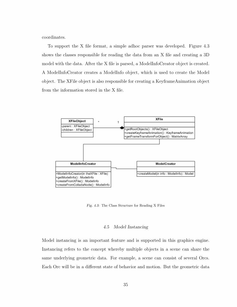
To support the X file format, a simple adhoc parser was developed. Figure 4.3
shows the classes responsible for reading the data from an X file and creating a 3D
model with the data. After the X file is parsed, a ModelInfoCreator object is created.
A ModelInfoCreator creates a ModelInfo object, which is used to create the Model
object. The XFile object is also responsible for creating a KeyframeAnimation object
from the information stored in the X file.
Fig. 4.3: The Class Structure for Reading X Files
4.5 Model Instancing
Model instancing is an important feature and is supported in this graphics engine.
Instancing refers to the concept whereby multiple objects in a scene can share the
same underlying geometric data. For example, a scene can consist of several Orcs.
Each Orc will be in a different state of behavior and motion. But the geometric data
35

for an Orc can be large, and if this data is duplicated for each Orc the system resources
can be quickly used up. Figure 4.4 shows the class structure for the representation
of 3D models. The geometrical data is contained in the Model class. The dynamic
properties of an object in the scene, including current position, are contained in the
SceneNode class.
Fig. 4.4: Model Class Structure With SceneNode
36
5. KEYFRAME ANIMATION
5.1 Overview of Keyframe Animation
Animation can refer to any dynamic motion of objects in a scene. A distinction is
made between real-time animation and pre-rendered animation. For real-time ani-
mation, the positions and orientations of objects are calculated when the program is
running. For pre-rendered animation, the positions and orientations of objects are
calculated before the program runs, and are stored in the file system. Due to the time
constraints of real-time applications, it is advantages to pre-compute animation se-
quences when possible. In some animation sequences, such as running or walking, the
motions are highly repetitive in nature and lend themselves to pre-computation with-
out loss of realism. One technique that uses pre-computed values is called keyframe
animation.
Keyframe animation is a technique that uses pre-calculated positions to represent
individual frames of an animated object. To get the position of an object at an instant
of time that is in between two keyframes, linear interpolation is applied between the
two frames to get the approximate position.
Using linear interpolation for rotations can have an interesting side-effect if the
angle of rotation between successive snapshots is too large. For example, a square is
to be rotated 90 degress in the counter-clockwise direction. If linear interpolation is
used for the rotation, the square appears to shrink as it rotates from 0 to 45 degrees,
and then increases in size as it rotates from 45 to 90 degrees. This is shown in
Figure 5.1.
37

Fig. 5.1: Distortion Effect When Rotating a Square
The effect is caused by performing a linear approximation of a cosine wave and a
sine wave. The x and y values for a rotating point are given by x = r * cos(a) and
y = r * sin(a), where r is the distance from the point to the axis of rotation and a
is the angle of rotation. Figure 5.2 shows the graph of a cosine wave, and Figure 5.3
shows the graph of a sine wave.
Fig. 5.2: Cosine Wave
38
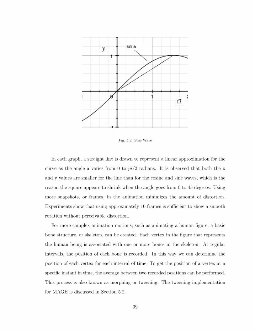
Fig. 5.3: Sine Wave
In each graph, a straight line is drawn to represent a linear approximation for the
curve as the angle a varies from 0 to pi/2 radians. It is observed that both the x
and y values are smaller for the line than for the cosine and sine waves, which is the
reason the square appears to shrink when the angle goes from 0 to 45 degrees. Using
more snapshots, or frames, in the animation minimizes the amount of distortion.
Experiments show that using approximately 10 frames is sufficient to show a smooth
rotation without perceivable distortion.
For more complex animation motions, such as animating a human figure, a basic
bone structure, or skeleton, can be created. Each vertex in the figure that represents
the human being is associated with one or more bones in the skeleton. At regular
intervals, the position of each bone is recorded. In this way we can determine the
position of each vertex for each interval of time. To get the position of a vertex at a
specific instant in time, the average between two recorded positions can be performed.
This process is also known as morphing or tweening. The tweening implementation
for MAGE is discussed in Section 5.2.
39
To get more realistic behavior for vertices, they can be associated with multiple
bones. The final position of each vertex is a weighted average between several bones.
Linear interpolation can also be used to get the final approximated position of each
vertex. This process is called skinning, since it used to simulate how skin is stretched
when connected bones move relative to each other. The skinning implementation for
MAGE is discussed in Section 5.3.
5.2 The Tweening Process
Each frame in a keyframe animation is a snapshot of the positioning of a skeleton,
which consists of a collection of bones. Each vertex is associated with a number of
bones. A bone is represented by a transformation, which determines the position of
the bone. A bones transformation is applied to the vertices that it influences. To
find the final position of a vertex for a given frame, its bone transformations are
applied to it. The first step is to get the bone transformations at a given instant
of time. This step is known a tweening. Assume an animation takes T seconds and
consists of N frames. So each frame has a time interval of T/N. For each bone, there
is a transformation defined for each interval. Let t0, t1, ..., tN represent the boundary
points for the time intervals. Let t be the current time, and assume 0 < t < N .
Then there is an i and j such that ti < t < tj. For each bone, we can get the
transformation at ti and tj, and then perform a linear interpolation computation to
get the transformation at t. Once we have all of the bone transformations at time
t, we can determine the influence of the bones on the vertices, which is the skinning
process and is discussed in Section 5.3. MAGE performs the tweening process in
a class called GeneralModel. This class reads a model from an X file. The model
could be a static model or it can include keyframes. The model can also have texture
coordinates and normals defined for it, in which case the GeneralModel class will
apply the appropriate operations to render it correctly. Below is the source code in
40
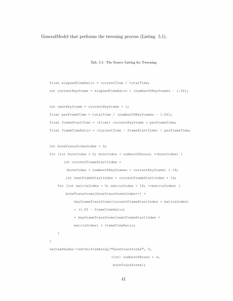
GeneralModel that performs the tweening process (Listing 5.1).
Tab. 5.1: The Source Listing for Tweening
float elapsedTimeRatio = currentTime / totalTime;
int currentKeyframe = elapsedTimeRatio * (numberOfKeyframes - 1.0f);
int nextKeyframe = currentKeyframe + 1;
float perFrameTime = totalTime / (numberOfKeyframes - 1.0f);
float frameStartTime = (float) currentKeyframe * perFrameTime;
float frameTimeRatio = (currentTime - frameStartTime) / perFrameTime;
int boneTransformsIndex = 0;
for (int boneIndex = 0; boneIndex < numberOfBones; ++boneIndex) {
int currentFrameStartIndex =
(boneIndex * numberOfKeyframes + currentKeyframe) * 16;
int nextFrameStartIndex = currentFrameStartIndex + 16;
for (int matrixIndex = 0; matrixIndex < 16; ++matrixIndex) {
boneTransforms[boneTransformsIndex++] =
keyframeTransforms[currentFrameStartIndex + matrixIndex]
* (1.0f - frameTimeRatio)
+ keyframeTransforms[nextFrameStartIndex +
matrixIndex] * frameTimeRatio;
}
}
vertexShader->setUniformArray("boneTransforms", 0,
(int) numberOfBones * 4,
boneTransforms);
41

The animation object is an instance of the KeyframeAnimation class shown in
Figure 5.4.
Fig. 5.4: The Animation Class Structure
5.3 The Skinning Process
The tweening process will determine the bone positions at a given time t. The next
step is to determine the influence of the bones on each vertex, which is called the
skinning process. Since this is a per-vertex operation, it can be more efficiently done
in a vertex shader.
For each vertex v, we get the bone transformations and bone weights that influence
the vertex. Assume that v is influenced by four bone transformations called B1, B2,
B3, and B4, and that the weights are, respectively, w1, w2, w3, and w4. An important
condition for the weights is that w1+w2+w3+w4 = 1. To calculate the final influence
on v, the linear interpolation equation is applied to get the resultant transformation
42
Br = w1 ∗B1 +w2 ∗B2 +w3 ∗B3 +w4 ∗B4. The resultant transformation Br is applied
to v to get its final position.
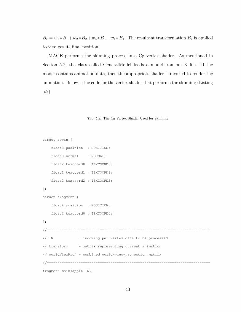
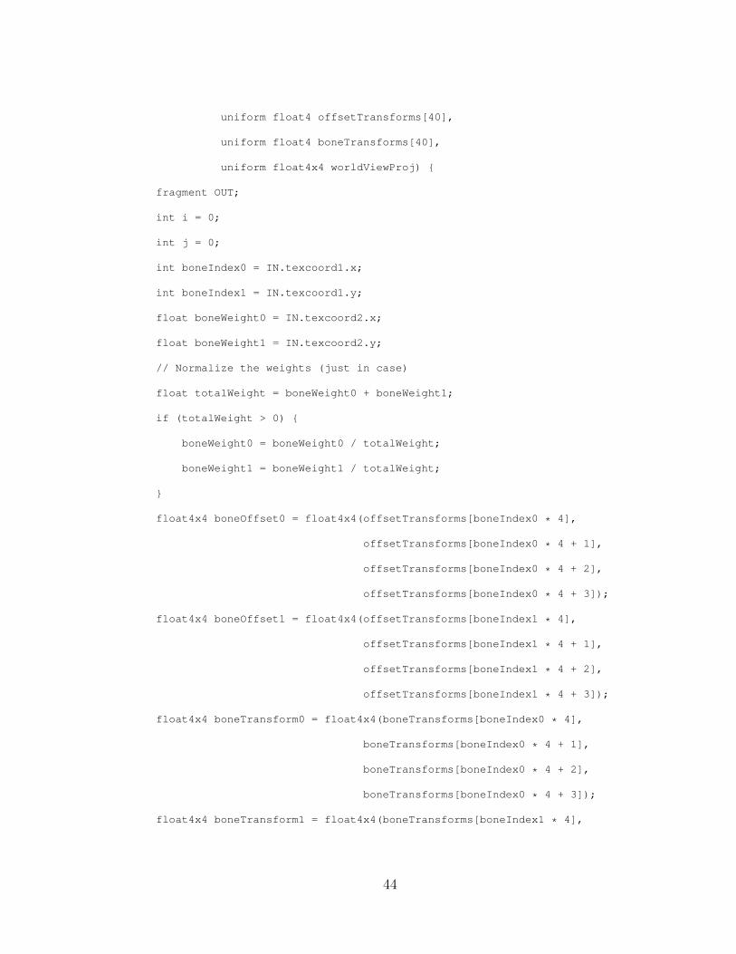
MAGE performs the skinning process in a Cg vertex shader. As mentioned in
Section 5.2, the class called GeneralModel loads a model from an X file. If the
model contains animation data, then the appropriate shader is invoked to render the
animation. Below is the code for the vertex shader that performs the skinning (Listing
5.2).
Tab. 5.2: The Cg Vertex Shader Used for Skinning
struct appin {
float3 position : POSITION;
float3 normal : NORMAL;
float2 texcoord0 : TEXCOORD0;
float2 texcoord1 : TEXCOORD1;
float2 texcoord2 : TEXCOORD2;
};
struct fragment {
float4 position : POSITION;
float2 texcoord0 : TEXCOORD0;
};
//-----------------------------------------------------------------------------
// IN - incoming per-vertex data to be processed
// transform - matrix representing current animation
// worldViewProj - combined world-view-projection matrix
//-----------------------------------------------------------------------------
fragment main(appin IN,
43
uniform float4 offsetTransforms[40],
uniform float4 boneTransforms[40],
uniform float4x4 worldViewProj) {
fragment OUT;
int i = 0;
int j = 0;
int boneIndex0 = IN.texcoord1.x;
int boneIndex1 = IN.texcoord1.y;
float boneWeight0 = IN.texcoord2.x;
float boneWeight1 = IN.texcoord2.y;
// Normalize the weights (just in case)
float totalWeight = boneWeight0 + boneWeight1;
if (totalWeight > 0) {
boneWeight0 = boneWeight0 / totalWeight;
boneWeight1 = boneWeight1 / totalWeight;
}
float4x4 boneOffset0 = float4x4(offsetTransforms[boneIndex0 * 4],
offsetTransforms[boneIndex0 * 4 + 1],
offsetTransforms[boneIndex0 * 4 + 2],
offsetTransforms[boneIndex0 * 4 + 3]);
float4x4 boneOffset1 = float4x4(offsetTransforms[boneIndex1 * 4],
offsetTransforms[boneIndex1 * 4 + 1],
offsetTransforms[boneIndex1 * 4 + 2],
offsetTransforms[boneIndex1 * 4 + 3]);
float4x4 boneTransform0 = float4x4(boneTransforms[boneIndex0 * 4],
boneTransforms[boneIndex0 * 4 + 1],
boneTransforms[boneIndex0 * 4 + 2],
boneTransforms[boneIndex0 * 4 + 3]);
float4x4 boneTransform1 = float4x4(boneTransforms[boneIndex1 * 4],
44

boneTransforms[boneIndex1 * 4 + 1],
boneTransforms[boneIndex1 * 4 + 2],
boneTransforms[boneIndex1 * 4 + 3]);
float4x4 boneResult0 = mul(boneOffset0, boneTransform0);
float4x4 boneResult1 = mul(boneOffset1, boneTransform1);
////////////////////////////////////////////////////////
//
// Interpolate the 2 bones according the the weights
//
////////////////////////////////////////////////////////
float4x4 resultTransform = float4x4(0,0,0,0,0,0,0,0,0,0,0,0,0,0,0,0);
// Do the interpolation to set the result animation transform
for (i = 0; i < 4; i++) {
for (j = 0; j < 4; j++) {
resultTransform[i][j] = boneWeight0 * boneResult0[i][j]
+ boneWeight1 * boneResult1[i][j];
}
}
/////////////////////////////////////////////////////////////
//
// Get the final position by applying the result transform
//
/////////////////////////////////////////////////////////////
float4 initialPosition = float4(IN.position.x,
IN.position.y,
IN.position.z,
1.0f);
float4 resultPosition = float4(IN.position.x,
45

IN.position.y,
IN.position.z,
1.0f);
resultPosition = mul(resultPosition, resultTransform);
// Vector on the right since worldViewProj matrix is transposed.
OUT.position = mul( worldViewProj, resultPosition);
// Pass texture coordinates to the fragment shader.
OUT.texcoord0 = IN.texcoord0;
return OUT;
}
46

6. EXAMPLES AND USAGE
One of the features provided by MAGE is the loading of 3D models from external
resource files. For example, a 3D model can be created using an open-source tool
called Blender [B1]. MAGE requires that the data exported from Blender follows a
strict format. Therefore, a tutorial is presented that shows how to create a 3D model
that can be used in MAGE. After the Blender tutorial, demonstration applications
that use Geng are discussed.
6.1 Using Blender to Create An Animated Model
Blender [B1] is an open-source application for creating 3D objects. It is the free
alternative to programs like 3D Studio Max and Maya, which can cost thousands of
dollars. Blender is available for Windows, Linux, and Mac OS X. This tutorial will
show how to create a very simple robot, how to add an animation sequence, how to
create the texture coordinates, and how to export the model to the X file format.
The tutorial will also cover the how to add the model to a scene using Geng and this
graphics engine.
When Blender is first opened, there is a default scene consisting of a cube, a light,
and a camera. The light and camera can be ignored for the purposes of this tutorial.
Initially there are two panels. There is the view panel and the button panel. The
view panel is used to edit the 3D model. The button panel is used to set various
properties of the model. In the lower left corner of the view panel is a 2D graph
showing the y-axis pointing up and the x-axis pointing to the right. This indicates
47
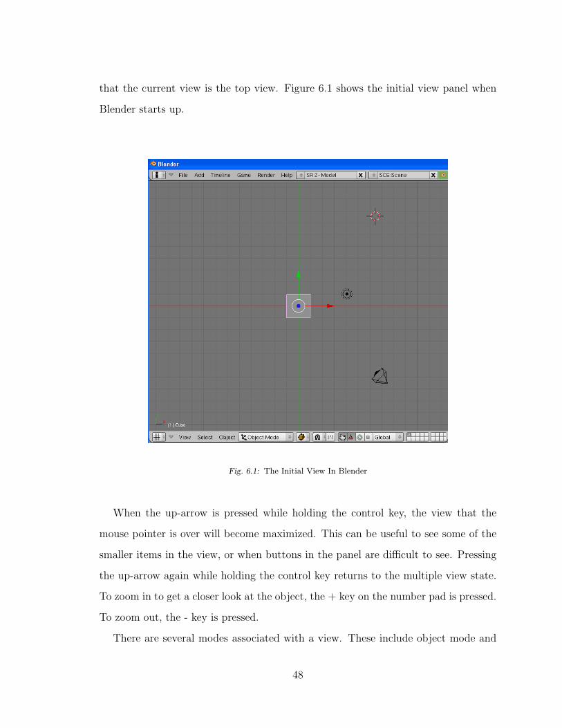
that the current view is the top view. Figure 6.1 shows the initial view panel when
Blender starts up.
Fig. 6.1: The Initial View In Blender
When the up-arrow is pressed while holding the control key, the view that the
mouse pointer is over will become maximized. This can be useful to see some of the
smaller items in the view, or when buttons in the panel are difficult to see. Pressing
the up-arrow again while holding the control key returns to the multiple view state.
To zoom in to get a closer look at the object, the + key on the number pad is pressed.
To zoom out, the - key is pressed.
There are several modes associated with a view. These include object mode and
48
edit mode. Initially the view is in object mode. Object mode is used to modify the
object as an individual unit. Edit mode is used to modify the individual vertices of
the object. Initially the view is in object mode.
The menu bar can be used to switch to the front view. This is done by pressing the
view menu and selecting front from the available choices. The first step is to move the
cube so that it is resting on the red line. This is done while in object mode. Pressing
the A key will toggle the selection of all the objects. Press the A key until all of the
objects are deselected, and then right-click on the cube to select only the cube. Once
the cube is selected, press G to grab the cube and move the mouse until the cube
is resting on the red line. The next step is to change the thickness of the cube. To
do this, switch to the side view and then switch to edit mode by pressing the TAB
key until Edit mode is displayed in the menu bar below the view. Groups of vertices
can be selected by pressing the B key and using the mouse. The left mouse button is
pressed and then the mouse is moved to create a rectangle. All of the vertices inside
the rectangle are selected. Select the vertices on the left of the cube, press the G
key to grab the vertices, and then use the mouse to move the vertices to the right.
Use the A key to deselect everything, then use the B key to grab the vertices on the
right and move them closer to the center. Now the object will be thinner, as shown
in Figure 6.2. The faces of the object can be made transparent by using the Z key
while in object mode.
49
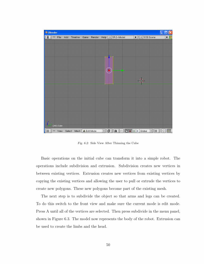
Fig. 6.2: Side View After Thinning the Cube
Basic operations on the initial cube can transform it into a simple robot. The
operations include subdivision and extrusion. Subdivision creates new vertices in
between existing vertices. Extrusion creates new vertices from existing vertices by
copying the existing vertices and allowing the user to pull or extrude the vertices to
create new polygons. These new polygons become part of the existing mesh.
The next step is to subdivide the object so that arms and legs can be created.
To do this switch to the front view and make sure the current mode is edit mode.
Press A until all of the vertices are selected. Then press subdivide in the menu panel,
shown in Figure 6.3. The model now represents the body of the robot. Extrusion can
be used to create the limbs and the head.
50

Fig. 6.3: The Subdivide Button in Blender
In edit mode and with all of the vertices deselected, select the two right-most
bottom vertices. Since this is a 3D model, the hidden vertices behind the selected
vertices should also be selected. Now press the E key and select Region from the
extrude menu. Then the mouse is moved to pull the vertices down to create a leg.
The G key can be used to grab the vertices to move them to the desired position.
This same process can be used to create the other leg, the arms, and the head. The
robot model is shown in Figure 6.4. This is a very crude model, but the same basic
operations can be used to create a much more detailed model.
51
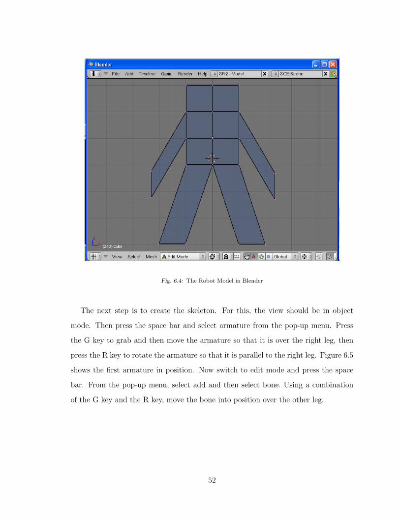
Fig. 6.4: The Robot Model in Blender
The next step is to create the skeleton. For this, the view should be in object
mode. Then press the space bar and select armature from the pop-up menu. Press
the G key to grab and then move the armature so that it is over the right leg, then
press the R key to rotate the armature so that it is parallel to the right leg. Figure 6.5
shows the first armature in position. Now switch to edit mode and press the space
bar. From the pop-up menu, select add and then select bone. Using a combination
of the G key and the R key, move the bone into position over the other leg.
52
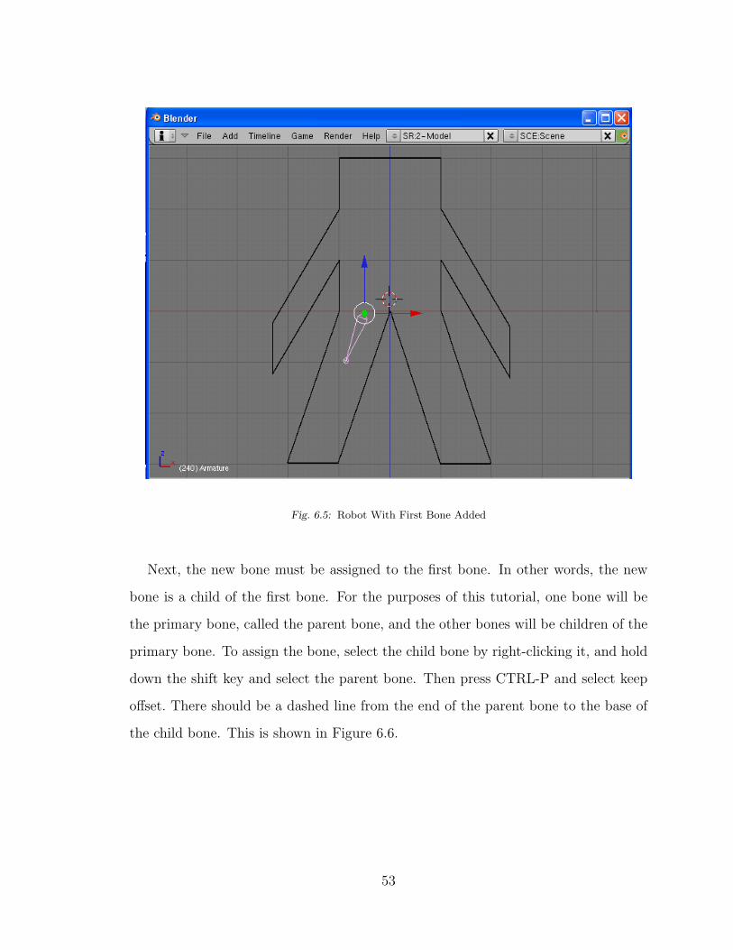
Fig. 6.5: Robot With First Bone Added
Next, the new bone must be assigned to the first bone. In other words, the new
bone is a child of the first bone. For the purposes of this tutorial, one bone will be
the primary bone, called the parent bone, and the other bones will be children of the
primary bone. To assign the bone, select the child bone by right-clicking it, and hold
down the shift key and select the parent bone. Then press CTRL-P and select keep
offset. There should be a dashed line from the end of the parent bone to the base of
the child bone. This is shown in Figure 6.6.
53
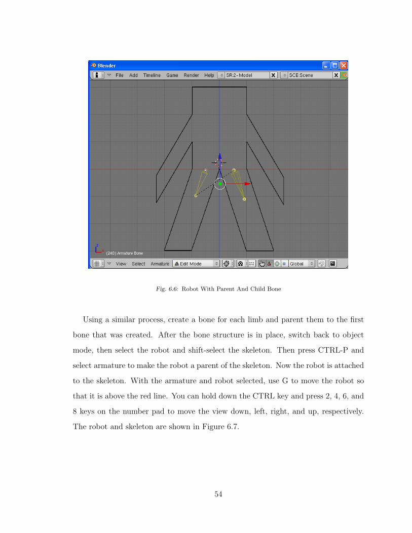
Fig. 6.6: Robot With Parent And Child Bone
Using a similar process, create a bone for each limb and parent them to the first
bone that was created. After the bone structure is in place, switch back to object
mode, then select the robot and shift-select the skeleton. Then press CTRL-P and
select armature to make the robot a parent of the skeleton. Now the robot is attached
to the skeleton. With the armature and robot selected, use G to move the robot so
that it is above the red line. You can hold down the CTRL key and press 2, 4, 6, and
8 keys on the number pad to move the view down, left, right, and up, respectively.
The robot and skeleton are shown in Figure 6.7.
54

Fig. 6.7: Blender With Skeleton
The next step is to assign vertices to the bones. Blender does its best to assign
vertices, but usually you will need to change the assignments. While in object mode,
select the robot, and then switch to edit mode. In the button panel, there is a vertex
groups panel. This is where vertices are assigned to the bones. First, select a bone
by name and then press the select button. This should select the vertices that the
specified bone is assigned to. To change the assignment press remove, then select the
vertices in the view pane, and then press assign in the vertex groups panel.
Once the vertices have been properly assigned to the bones, it is time to create the
keyframes. Just below the Figure is a small window with a 1 in it. This indicates the
current frame. The small arrows can be pressed to increase or decrease the current
55
frame number. Switch back to object mode and select the skeleton. Then switch to
pose mode. Now the individual bones can be selected, moved, and rotated to their
desired placement. Once the bones are in their proper positions, select all of the bones
using the A key and then press the I key. Select LocRot from the pop-up menu. Now
the transformations are set for the current frame. The same process can be repeated
for any number of frames until the desired animation sequence has been created.
The next step is to create the texture coordinates so that texture mapping can be
used with the model. Select the robot and switch to edit mode. Seams need to be
created. The robot will be unfolded onto a flat surface using the seams. To create a
seam, select the vertices for the seam and press CTRL-E, and then select mark seam.
Once all of the seams are created, press the U key and select unwrap in the pop-up
menu. This will perform the operation that maps the 3D model to a 2D surface. The
last thing to do is export the model to the proper format.
Before saving the model, make sure double sided in the buttons panel is not se-
lected. In edit mode, press CTRL-N and select recalculate normals outside. Then
save the blender file. Once the blender file is saved, export the file to the X file for-
mat, also called the DirectX format. In the export screen, select anim to export the
animations, select Flip z to select left-handed coordinate system, then select export
all. Now the model is ready to use in the graphics engine.
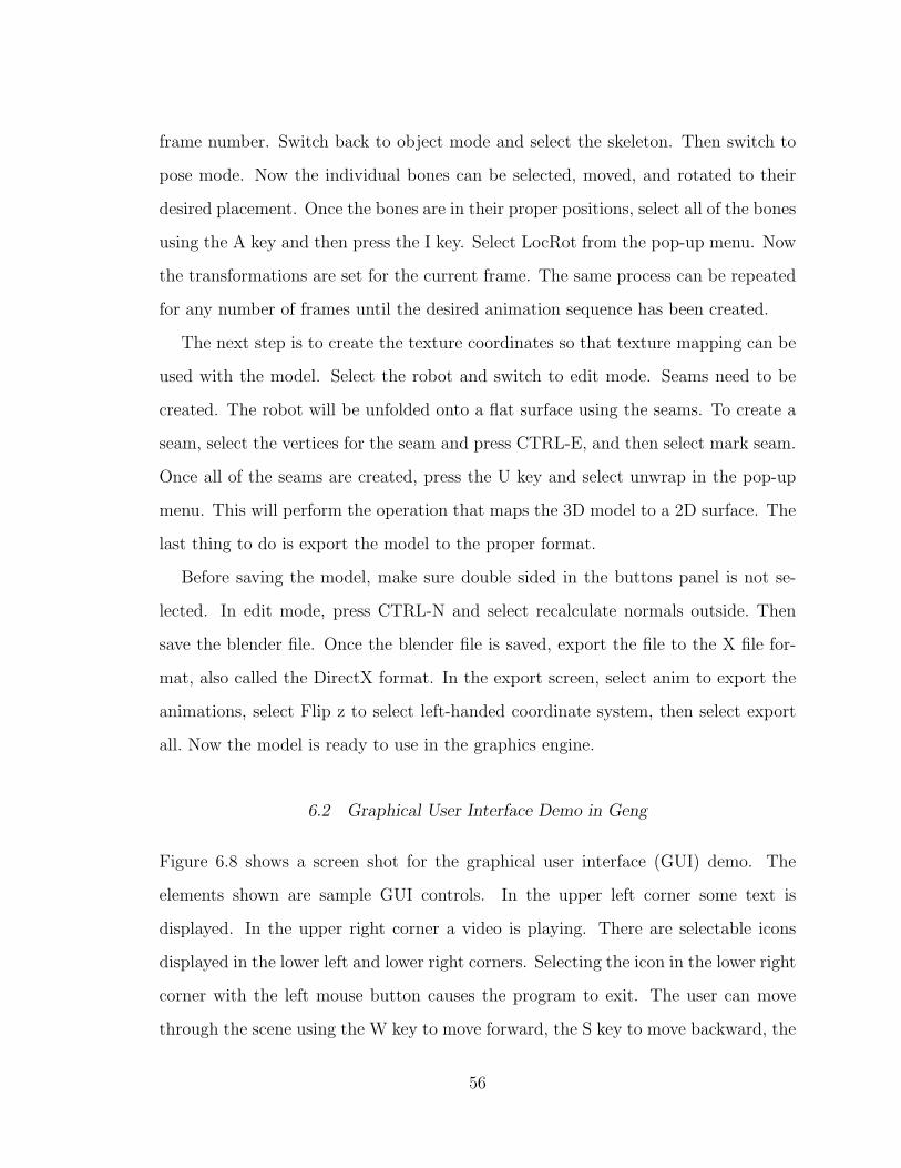
6.2 Graphical User Interface Demo in Geng
Figure 6.8 shows a screen shot for the graphical user interface (GUI) demo. The
elements shown are sample GUI controls. In the upper left corner some text is
displayed. In the upper right corner a video is playing. There are selectable icons
displayed in the lower left and lower right corners. Selecting the icon in the lower right
corner with the left mouse button causes the program to exit. The user can move
through the scene using the W key to move forward, the S key to move backward, the
56

A key to strafe left, and the D key to strafe right. If the user holds the right mouse
button, moving the mouse will control the direction of the camera.
Fig. 6.8: The Graphics Engine Demo Using Geng
6.3 Physics Demo in Geng
A box is shown near the center of the view, as seen in Figure 6.8. The box represents
a static object in the scene. As the user uses the W key to move forward, the user will
collide with the box, halting the forward motion, and will slide off of the box. The
collision detection and sliding effect are handled in the Bullet physics engine [B2].
57

6.4 Animation Demo
Several animated robots have been placed at random locations in the scene, as seen
in figure 6.9. These robots were created in Blender [B1] and exported in the X file
format. One of the robots is caused to wander around the scene, and the other robots
are chasing it. As the robots move beyond the boundary, they reappear at the other
side. As the wandering robot moves beyond the boundary and reappears at the other
side, it is interesting to see the pursuing robots change direction. The source code for
the AI is provided by the AI textbook found in [B10]. The user can use the movement
keys W, S, A, and D, to move through the scene and take part in the chasing.
Fig. 6.9: Robots Chasing Each Other
58
7. FUTURE WORK AND CONCLUSION
7.1 Future Work
Although MAGE provides the basic graphics support needed by a 3D application,
the features it has can be improved, and new features can be added. For example,
MAGE supports 3D models with single keyframe animation sequences, but does not
support multiple keyframe animation sequences. The following sections discuss some
additional improvements that can be added to MAGE.
7.1.1 Multiple Animation Sequences
Currently the graphics engine supports single animation sequences. That is, a graph-
ics object can have only one animation associated with it. This functionality should
be extended to support multiple animations per model. For example, the animation
sequences may include a running animation, a walking animation, an idle animation,
and an attacking animation.
In order to support multiple animations, it is also necessary to support the blending
between animations. This avoids sudden changes in motion caused when switching
between animations. One animation should have a smooth transition to another
animation.
7.1.2 Terrain
The graphical representation of terrain is supported by the graphics engine since
terrain can be by a textured mesh. But there is more to real terrain than a simple
59
mesh. One necessary improvement is support for a height map. This allows the
physics engine to properly place objects on the terrain and perform collision detection
with the terrain. Another requirement for terrain support is space partitioning.
To support a large virtual world, a large terrain is required. The standard practice
is to split the terrain into smaller sections called quads. The quads are placed in
a special data structure called a partitioning tree. The partitioning tree can then
be used to load only the sections of the terrain that are in the viewable area. So
support for a space partitioning tree should be added to the graphics engine. An
excellent reference for creating space partitioning trees and other advanced topics for
the development of terrain can be found in [B12].
7.1.3 Shadows
There are several techniques for calculating shadows in real-time. The simplest and
most limited uses projection. For this technique each model is drawn twice. First the
model is drawn normally, and second a projection transformation is applied to the
model to essentially flatten it, and then it is drawn with a dark color to represent the
shadow.
There are two remaining techniques that are more advanced, and new functionality
must be added to the Graphics class to support them. One technique is called volume
shadows, and uses the depth buffer to determine what pixels are in a shadow. Another
technique uses the stencil buffer to determine which pixels are in a shadow. To support
these techniques, access to the depth buffer and stencil buffer will need to be added
to the graphics engine.
7.1.4 Reflections
Real-time reflections can be added by using environment mapping. Essentially, the
scene is drawn to an off-screen buffer from the perspective of the objects that are
60
reflected. The off-screen buffer is then converted to an image and a texture object is
created for the image. Then the texture is applied to the objects that are reflecting.
In order to support this functionality, the ability to draw to an off-screen buffer
will need to be added. Additionally, support for creating a texture object using the
off-screen buffer will need to be added.
7.1.5 Three-dimensional Text
Text is currently supported by this graphics engine, and is implemented in the context
of an overlay element. This limits the use of text to the graphical user interface. It
would be valuable to be able to display text within the 3D virtual world. Since the
current text implementation uses texture mapping as its basis, it should be a straight
forward process to create a 3D text class that can be used to display text on 3D
objects within the 3D scene.
7.1.6 Three-dimensional Video
For some applications, it may be desirable to play a video on the polygonal surfaces of
3D models. Video, like text, is currently supported only in the context of an overlay
element. Also similar to the implementation of text, video has texture mapping as
its basis, and therefore it should be a straightforward process to use video within the
3D scene.
7.2 Conclusion
Mythic is a new 3D game being developed at CSUSB. A game engine called Geng
is being developed for use by Mythic. The subject of this paper is a project called
MAGE, which is the core graphics engine used by Geng.
Real-time interactive 3D graphics is a complex problem that brings together many
different fields of study. This includes linear algebra, classical physics, artificial intel-
61

ligence, computer architecture and optimization, as well as many other fields. This is
further complicated by the ever changing technological landscape and the multitude
of libraries available, which includes OpenGL and Direct3D.
MAGE can be used as the rendering vehicle for creating 3D real-time interac-
tive computer applications. Support is provided for creating graphical user interface
controls, including the use of text and playing movies. Support is also provided for
importing models created using Blender and adding the models to a 3D virtual scene.
The models created can include keyframe animation sequences. Attention has been
paid to the efficient rendering of models via the use of vertex and index buffers, vertex
and fragment shaders, and model instancing. Support for pixel-perfect 3D picking
is provided for applications that require the real-time selection of 3D models in the
scene.
Particular attention has been paid to fundamental design concepts, so the graphics
engine can be used as a pedagogical tool for teaching how to develop a 3D graphics
engine. The implementation of fundamental rendering concepts using both OpenGL
and Direct3D is an advantage to students for the understanding of core concepts. A
deeper understanding of these concepts can be gained by comparing and contrasting
the two implementations.
The graphics engine developed also supports multiple platforms, including Win-
dows, Linux, and Mac OS X. The graphics API developed both simplifies the program-
ming process and provides support for advanced features. For Windows development,
support is provided for both OpenGL and Direct3D. Besides allowing the program-
mer to choose the underlying API that provides the best performance, an additional
advantage is gained in the development process. That is, if a new feature does not
work for either OpenGL or Direct3D, then it is likely that the underlying logic of the
new feature is faulty. If it works for one but not the other, then this is an indication
that the logic is correct, so the programmer can focus on the one that is not working.
62

Once the feature is working for both underlying APIs, the logic can be modified until
the functionality is visually equivalent for both. The visual equivalency of the feature
for both APIs serves as a positive indicator that the feature has been implemented
successfully.
63
BIBLIOGRAPHY
[B1] Blender Web Page, http://www.blender.org/.
[B2] Bullet Web Page, http://bulletphysics.org/wordpress/.
[B3] Google Commons, http://commons.wikimedia.org.
[B4] Mythic Home Page, http://cse.csusb.edu/games/mythic/.
[B5] Nvidia Developer Home Page, http://developer.nvidia.com/.
[B6] OpenGL Home Page, http://www.opengl.org/.
[B7] Akenine-Moller, T., Real-time Rendering, 2nd Ed. A. K. Peters, 2002.
[B8] Buss, S., 3-D Computer Graphics - A Mathematical Introduction with OpenGL
Cambridge Press, 2003.
[B9] Granberg, C., Programming an RTS Game with Direct3D Charles River Media,
2007.
[B10] Millington, I., and Funge, J., Artificial Intelligence for Games Morgan Kauf-
mann, 2009.
[B11] Munshi, A., Ginsburg, D., and Shreiner, D., OpenGL ES 2.0 Programming
Guide Addison Wesley, 2009.
[B12] Snook, G., Real-time 3D Terrain Engines using C++ and DirectX 9 Charles
River Media, 2003.
64

[B13] Yu, T., Turner, D., Concepcion, A., and Stover, D., “Incorporating Video
in Platform-Independent Video Games Using Open-Source Software,” Third
IEEE International Conference on Computer Science and Information Technol-
ogy , July 2010.
65

66


![Image Rendering by Adaptive Refinementfuchs//publications/Bergman1986.pdf · Graphics]: Picture/Image Generation -- Display algorithms, 1.3.7 [Computer Graphics]: Three-Dimensional](https://img.pdfslide.us/doc/110x75/5ff6b7cc840fc932077bf59c/image-rendering-by-adaptive-fuchspublicationsbergman1986pdf-graphics-pictureimage.jpg)

![Blending Liquids - Georgia Institute of Technologyturk/my_papers/blending_liquids.pdf · Blending Liquids Karthik Raveendran ... [Computer Graphics]: Three-Dimensional Graphics and](https://img.pdfslide.us/doc/110x75/5b5d28297f8b9ad21d8d938f/blending-liquids-georgia-institute-of-turkmypapersblendingliquidspdf.jpg)