Embed Size (px)
Citation preview

-- I
UNAVAILABLE REMOVED PER LETTER DTD 1-25-85 "" ."
f o r t h e
Bureau of Aeronautics, Department of the Navy
FLIGHT TESTS O F A 0.13-SCALF: MODEL OF TEE
COWAIR XFY-1 VET<ZCALLY R I S I X G AIRPLANE
WITH THE LOWER VERTICAL TAIL REMOVED
TED NO. NACA DE 368
t By Powell M. Lovell, Jr.
Langley Aeronautical Laboratory, Langley Fie ld , Va. . .
of the espionage laws, n t l e 18, U.S.C., Secs. 193 and 794, the transmlssion or revelation of which in any This material contains information affecting the National Defense of the Unlted States within the meaning
manner to an unauthorized person is prohibited by law.
NATIONAL ADVISORY COMMITTEE FOR. AERONAUTICS
Restriction/Classification Cancelled

.
NACA RM SLf54E07
NATIONAL ADVISORY COMMITTEE FOR AERONAUTICS
RESEARCH ME"
for the
Bureau of Aeronautics, Department of the Navy
FLIGHT TESTS OF A 0.13-SCALE MODEL OF THE
CONVAlR XFY-1 VERTICALLY RISING AlRPLANE
W I T E THF3 LOWER VERTICAL TAIL RFsI0YEI.l
TED NO. NACA DE 368
By Powell M. Lovell, Jr .
SUMMARY
An experimental investigation has been conducted to determine the dynamic stability and control characteristics in hovering and transition flight of a 0.13-scale flying model of the Convair XFY-1 vertically rising airplane with the lower vertical tail removed. "he purpose of the tests was to obtain a general indication of the behavior of a verti- cally rising airplane of the same general type as the XFY-1 but without a lower vertical tail in order to simplify power-off belly landings in an emergency.
The model was flown satisfactorily in hovering flight and in the transition from hovering to normal unstalled forward flight (angle of attack approximately 30°). F r o m an angle of attack of about 30° down to the lowest angle of attack covered in the flight tests (approxi- mately 13O) the model became progressively more difficult to control. These control difficulties were attributed partly to a lightly damped Dutch roll oscillation and partly to the fact that the control deflec- tions required for hovering and transition flight were too great for smooth flight at high speeds. In the low-angle-of-attack range not covered in the flight tests, force tests have indicated very low static directional stability which would probably result in poor flight char- acteristics. It appears, therefore, that the attainment of satisfactory directional stability, at angles of attack less than loo, rather than in the hovering and trans-ition ranges of flight is the critical factor in
' . the design of the vertical tail for such a configuration.

2
INTRODUCTION
NACA RM SL54E07
At the request of the Bureau of Aeronautics, Department of the Navy, an investigation is being conducted to determine the dynamic stability and control characteristics of a 0.13-scale model of the Convair XFY-1 vertically rising airplane. The first phase of the investigation, which was reported in reference 1, dealt with hovering flight at altitude and near the ground, various landing techniques using tethering lines to pull the model down to the ground, unrestrained take-offs and landings, and low-speed forward flight in gusty wind. The second phase of the investigation was reported in reference 2 and covered the transition range of flight between hovering and normal unstalled forward flight.
The airplane 'has a modified triangular wing and modified triangular vertical-tail surfaces mounted symmetrically above and below the fuselage but has no horizontal tail. The airplane has a large dual-rotating propeller and sufficient power to take off and land vertically. Control is provided by flap-type elevons and rudders operating in the propeller slipstream. Because of the large lower vertical tail, emergency belly landings in the event of a power failure do not appear feasible. The present series of tests were made, therefore, to determine whether a model of generally similar configuration but without a lower vertical tail could be flown satisfactorily in hovering flight and through the transition range from hovering to normal unstalled forward flight. The information derived from the tests is intended primarily as a basis for future designs of vertically rising airplanes rather than for direct application to the XFY-1, since this airplane would probably require more vertical-tail area than is afforded by the upper vertical tail alone. The XFY-1 model was used, however, because it was readily available.
The results of the investigation were obtained primarily from the pilots' observations of the stability and controllability of the model. In addition, some time histories of the motions of the model were pre- pared from motion-picture records of the flights to aid in the study of particular phases of the behavior of the model.
NOMENCLATURE AND SYMBOLS
In order to avoid confusion in terminology which might arise because of the large range of operating attitudes of the model, it should be explained that the controls and motions of the model are referred to in conventional terms relative to the body system of axes; that is, the rudder on the vertical tail produces yaw about the normal axis, differ- ential deflection of the elevons on the wings produces roll about the

NACA RM SL54E07 - 3
fuselage axis, and simultaneous up or down deflection of the elevons produces pitch about the spanwise axis. Figure 1 shows the axes and the positive directions of the linear and angular displacements.
The definitions of the symbols used in the present paper are as follows :
airspeed, mph
angle of pitch of thrust axis relative to horizontal, deg
angle of yaw, positive for right yaw; measured from the vertical in the plane shown by the rear camera
time, sec
mean aerodynamic chord
rate of change of yawing-moment coefficient with sideslip angle
yawing-moment coefficient, N/qSb
rate of change of rolling-moment coefficient with sideslip angle
rolling-moment coefficient, 2/qSb
sideslip angle, radians
yawing moment, ft-lb
rolling moment, ft-lb
dynamic pressure, --pV 1 2 , lb/sq ft
area of wing, sq ft
span of wing, ft
wing angle of attack, deg
APPARATUS AND MODEL
The investigation was conducted by the Langley free-flight-tunnel section in the return passage and in the 30- by 60-foot test section of -

I I I 1 I I
4 NACA RM SL’J4E07
the Langley full-scale tunnel by using the test setups for hovering and transition flight described in references 1 and 2, respectively.
A multiple-exposure photograph showing the model sitting on the full-scale-tunnel ground board and in hovering and transition flight is shown in figure 2. A sketch showing some of the more important dimen- sions of the model is shown in figure 3 and the geometric character- istics are presented in detail in table I. The model was the same one used in the investigations of references 1 and 2 except that the lower vertical tail was removed. The model had an eight-blade dual-rotating, fixed-pitch propeller (two four-blade elements in tandemj powered by a 5-horsepower electric motor.
Maneuvering was accomplished by means of flap-type elevons and a rudder operating in the propeller slipstream. The control surfaces were deflected by flicker-type (full-on, full-off) pneumatic actuators which were remotely operated by the pilots. These actuators were equipped with integrating-type trimmers which trimed the controls a small amount in the direction the controls were moved each time a control movement was applied. With actuators of-this type, the model became accurately trimed after flying a short time in a given flight condition. Separate pilots were used to control the model in pitch, roll, and yaw in order that they might give careful attention to studying the motions of the model about each of the axes. In some of the hovering flights a rate- gyro roll-damping device was used; but for most of the hovering flights and all of the transition flights, no automatic stabilization devices were used in the roll control system. A yaw damper was used during all of the transition flights but was not used in any of the hovering flights. No automatic trimming devices were used in the control systems in which dampers were used. The operation of these damping devices is explained in detail in reference 2.
TESTS
The investigation covered in the present paper consisted entirely of flight tests of the model. The stability and controllability of the model were determined from the pilots’ observations and opinions of the behavior of the model, from the study of motion-picture records of the flight tests, and from time-history plots of the motions of the model read from the motion-picture records.
The present series of tests were much less detailed than the previous tests of the model with both upper and lower vertical tails since the present tests were intended to show only whether the removal of the lower vertical tail caused any major differences in the overall
NACA RM SL54E07 - 5
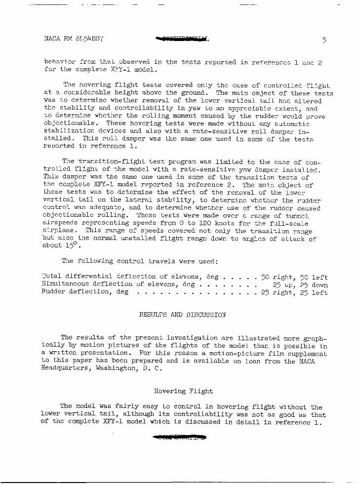
behavior f rom that observed in the tests reported in references 1 and 2 for the complete XFY-1 model.
The hovering flight tests covered only the case of controlled flight at a considerable height above the ground. The main object of these tests was to determine whether removal of the lower vertical tail had altered the stability and controllability in yaw to an appreciable extent, and to determine whether the rolling moment caused by the rudder would prove objectionable. These hovering tests were made without any automatic stabilization devices and also with a rate-sensitive roll damper in- stalled. This roll damper was the same one used in some of the tests reported in reference 1.
The transition-flight test program was limited to the case of con- trolled flight of the model with a rate-sensitive yaw damper installed. This damper was the same one used in some of the transition tests of the complete XFY-1 model reported in reference 2. The main object of these tests was to determine the effect of the removal of the lower vertical tail on the lateral stability, to determine whether the rudder control was adequate, and to determine whether use of the rudder caused objectionable rolling. These tests were made over a range of tunnel airspeeds representing speeds from 0 to 120 knots for the full-scale airplane. This range of speeds covered not only the transition range but also the normal unstalled flight range down to angles of attack of about 1.5' .
The following control travels were used:
Total differential deflection of elevons, deg . . . . . 50 right, 50 left Simultaneous deflection of elevons, deg . . . . . . . 25 up, 25 down Rudder deflection, deg . . . . . . . . . . . . . . . . 25 right, 25 left
RESULTS AND DISCUSSION
The results of the present investigation are illustrated more graph- ically by motion pictures of the flights of the model than is possible in a written presentation. For this reason a motion-picture film supplement to this paper has been prepared and is available on loan from the NACA Headquarters, Washington, D. C.
Hovering Flight
The model was fairly easy to control in hovering flight without the lower vertical tail, although its controllability was not as good as that of the complete XI%-1 model which is discussed in detail in reference 1.

It was evident to the pilot that without the lower vertical tail the model had less rudder effectiveness than the complete model and that he was, therefore, required to control the model more carefully and to main- tain a more nearly vertical attitude at all times. The available control power was too little to erect the model and stop the sidewise transla- tion within the limits of displacement allowed by the safety cable if the model were allowed to reach a fairly large angle of yaw (about 15') .
No difficulty was encountered in controlling the rolling motions of the model without the roll damper operating even though a rudder deflec- tion obviously produced a rolling moment as well as a yawing moment. Apparently the rolling motions of the model were slow enough and the elevons powerful enough to allow the r o l l pilot to maintain the model in proper roll orientation very easily. The rolling motions were some- what smoother and slower when the r o l l damper was operating than when it was not operating.
The control characteristics in pitch seemed, as would be expected, identical to those noted for the complete model and are discussed in detail in reference 1.
Transition Flight
The model could be flown smoothly through the complete transition between hovering and normal unstalled forward flight (angle of attack approximately 30"). Figure 4 presents time histories of the yawing and pitching motions of the model and airspeed and control movements during a complete flight. In the transition range (approximately 90' to 30° angle of attack), the model appeared to have about the same stability and control characteristics as those observed during the investigation of reference 2. The rolling motions were easy to control at angles of attack above about 30' even though the model was out of trim f o r a large portion of the transition. The roll-control movements shown in figure 4 indicate that the model became trimmed in r o l l shortly before reaching about 50' angle of attack and, since only a few r o l l control movements were required at angles of attack between 50' and 30°, it appeared that the model had stability in bank about the body axis (or positive dihedral effect) in this range as had been the case for the complete XFY-1 model.
The behavior of the model in yaw was generally satisfactory over the entire transition range of flight. As in the case of the complete model of the XFY-I., however, the stability of the model was somewhat worse at angles of attack between 40° and 50' than over the rest of the transition range, and the pilot had some difficulty in controlling the model in this angle-of-attack range. This difficulty is evident in the time history of figure 4 which shows that there was an increase in the amplitude of the yawing motions at angles of attack between 40° and 50'.

NACA RM SL54E07 Wmmmmm 7
Since the behavior of the model with the yaw damper seemed very similar to that observed for the complete XFY-1 model with the yaw damper, the characteristics of the model without a yaw damper might be expected to be similar to those of the XFY-1 model without a yaw damper. It seems likely, therefore, that the model could be flown through the transition range without the yaw damper although the behavior would be expected to be less satisfactory than it was with the yaw damper, particularly at angles of attack between 40' and 50'. It appears from a comparison of the results of the present tests with those for the complete XFY-1 model that, during the transition range of flight, the lower vertical tail did not contribute much to the directional stability, probably because the propeller slipstream was being blown upward and was not covering much of the lower tail.
The stability and control characteristics of the model in pitch seemed exactly the same as those of the complete XFY-1 model. The model was easy to fly in pitch and seemed to have stability of angle of attack over much of the speed range. The rapid variations of angle of pitch about the mean value which are evident in figure 4 did not seem to be caused by poor stability but seemed to result partly from the difficulty in coordinating thrust and pitch controls as the airspeed increased, and partly because the large elevator travel (2.25') required to enable the pilot to correct for the large changes in trim was too great to permit smooth flight. (The trimming devices on the flicker-type control actu- ators did not change the setting of the elevator control surfaces rapidly enough to keep the model in trim during transition flight.)
Normal Unstalled Flight
At angles of attack below about 30' the model became difficult to control in roll and at an angle of attack of about 15' sustained flight was impossible. Every transition flight was terminated at about 15' angle of attack because of the difficulty experienced in controlling the rolling motions.
The roll pilot felt that this difficulty resulted partly from a tendency for him to overcontrol because the aileron travel was too high (f50°) for smooth flight at the higher speeds and partly from the rolling caused by the rudder. The use of coordinated r o l l and yaw controls would probably make the motions easier to control. Examination of the motion- picture records of the flight tests indicated that another cause of the difficulty experienced in controlling the rolling motions might be that the model had too much dihedral effect and that the Dutch roll oscilla- tion was not heavily damped. The fact that the effective dihedral of the model was greater with the lower vertical tail removed than for the complete XFY-1 model is shown by the force test data of figure 5 which were computed from data taken from reference 3. The motions looked very

8 NACA .RM SL54E07
much like those experienced in the Langley free-flight tunnel with models in which the trouble could definitely be attributed to excessive dihedral effect and too little Dutch roll damping. The pilot has difficulty in controlling such motions and often applies controls in phase with the Dutch roll, thereby reinforcing instead of damping it.
As indicated by the time history of the angle of yaw in figure 4, the yawing motions became more violent and difficult to control at angles of attack below about 30'. This difficulty in controlling the yawing motions can probably be attributed largely to the fact that the rudder deflections were too large for smooth flight at these speeds and to the fact that the model was practically always out of trim since the rudder actuator did not incorporate an automatic trirmning device. Because of the out-of-trim moments, the pilot had to give frequent left rudder deflections, so that the model was continually being disturbed by large rudder yawing moments. The data of reference 2 indicate that, with the lower vertical tail on, the pilot had no appreciable difficulty control- ling the model directionally at angles of attack below about 40°. It was the feeling of the pilot, therefore, that in the unstalled flight range the lower vertical tail makes an important contribution to the directional stability of the model. The actual magnitude of the contri- bution of the vertical tails to the static directional stability is illustrated in figure 5, which was computed from the force-test data of reference 3; These data indicate that the static directional stability of the model without the lower vertical tail was considerably less than that of the complete model.
The characteristics of the model in pitch seemed identical to those noticed during the investigation of the complete XFY-1 model. The rapid variations in pitch about the mean value (in the normal flight range) which are evident in figure 4 seemed to be caused mostly by overcontrolling because the elevator travel (i23O) was excessive for angles of attack below about 30'.
APPLICATION OF RESULTS
The results of the present investigation might be applied to either of two cases - to an airplane designed to have only an upper vertical tail, or to the XFY-1 airplane in an emergency condition in which the lower vertical tail is jettisoned to permit a belly landing in the event of a power failure. Although this latter condition is not currently planned for the airplane, it has been suggested as a possibility in order to avoid demolishing the airplane in the event of a power failure.

NACA RM SL54E07 - 9
For an airplane designed to have only an upper vertical tail, the results of the present tests indicate that it is probably possible to design an airplane of this type that will have acceptable stability and control characteristics over the entire speed range. The force-test data of figure 5 indicate that an airplane of this type should have a larger vertical tail than the upper vertical tail of the XFY-1 to pro- vide adequate directional stability at very low angles of attack (angles near 0'). It seems likely that the larger tail would improve the behavior at angles of attack between 15' and 30' since it would give a larger percentage increase in directional stability than in effective dihedral. It appears also that there is no reason to believe that the larger tail would have any appreciable adverse effect on stability and control characteristics in the transition and hovering flight conditions.
For the case of the XFY-1 airplane with the lower vertical tail removed, the results of the tests indicate that it should be possible to fly the airplane in a condition in which an emergency belly landing could be made. In the event of a partial power failure, the airplane could be flown satisfactorily to as low a speed as possible with the thrust available. The tests indicate that it might be important, how- ever, to avoid going to too low an angle of attack after the lower tail had been jettisoned since lateral-stability and control difficulties might be encountered. In the event of a complete power failure, land- ings of the XFY-1 with the lower tail removed might be dangerous since, as shown by the force-test data of figure 6, it is about neutrally directionally stable at angles of attack below about 10' with zero thrust. At angles of attack between about 10' and 20°, however, these data show that the XFY-1 should be directionally stable with power off. It might be possible, therefore, to accomplish an emergency landing in this condition.
Langley Aeronautical Laboratory, National Advisory Committee for Aeronautics,
Langley Field, Va., April 28, 1.954.
Q d h . *p* Powell M. Lovell, Jr.
Aeronautical Research Scientist
Approved : Thomas A . Harris
Chief of Stability Research Division
BS

10 NACA RM SL54E07
REFERENCES
1. Lovell, Powell M., Jr., Smith, Charles C., Jr., and Kirby, Robert H.: Stability and Control Flight Tests of a 0.13-Scale Model of the Consolidated-Vultee )(Fy-1 Airplane in Take-Offs, Landings, and Hovering Flight - TED No. NACA DE 368. NACA RM ~~52126, Bur. Aero., 1952
2. Lovell, Powell M., Jr., Kirby, Robert H., and Smith, Charles C., Jr.: Flight Investigation of the Stability and Control Characteristics of a 0.13-Scale Model of the Convair XFY-1 Vertically Rising Air- plane During Constant-Altitude Transitions - TED No. NACA DE 368. NACA RM SL53E18, Bur. Aero., 1953.
3. Queijo, M. J., Wolhart, W. D., and Fletcher, H. S.: Wind"D.mnel Investigation at Low Speed of the Static Longitudinal and Lateral Stability Characteristics of a l/g-Scale Powered Model of the Convair XFY-1 Vertically Rising Airplane - TED No. NACA DE 373. NACA RM SL33B20, Bur. Aero., 1953.

NACA RM SL9E07 emmMwRw 11
TABLE I
GEOMETRIC CHARACTERISTICS OF MODEL
Weight. lb . . . . . . . . . . . . . . . . . . . . . . . . . . . 35.00
Wing (modified triangular plan f o m ) : Sweepback. deg . . . . . . . . . . . . . . . . . . . . Airfo i l sec t ion . . . . . . . . . . . . . . . . NACA A s p e c t r a t i o . . . . . . . . . . . . . . . . . . . . . Taper r a t i o ( r o o t t o t h e o r e t i c a l t i p ) . . . . . . . . . Area ( t o t a l t o c e n t e r l i n e ) . sq i n . . . . . . . . . . Span ( theo re t i ca l ) . i n . . . . . . . . . . . . . . . . Mean aerodynamic chord. i n . . . . . . . . . . . . . . Span of elevon (each). i n . . . . . . . . . . . . . . . Chord of elevon. i n . . . . . . . . . . . . . . . . . . Dihedral angle. deg . . . . . . . . . . . . . . . . .
. . . . 55 63-009 modified . . . . 1.90 . . . . 5.23 . . . . 818.95 . . . . 39.49 . . . . 23.94 . . . . 15.37 . . . . 2.92 . . . . 0
Overall length of model. i n . . . . . . . . . . . . . . . . . . . 49.40 Fuselage length. i n . . . . . . . . . . . . . . . . . . . . . . . 45.40
Vert ical t a i l s (modified triangular plan form) : Sweepback. deg . . . . . . . . . . . . . . . . . . . . Airfo i l sec t ion . . . . . . . . . . . . . . . . NACA A s p e c t r a t i o . . . . . . . . . . . . . . . . . . . . . Taper r a t i o ( r o o t t o t h e o r e t i c a l t i p ) . . . . . . . . Area ( t o t a l t o center l ine) . sq i n . . . . . . . . . . Span. i n . . . . . . . . . . . . . . . . . . . . . . . Mean aerodynamic chord. i n . . . . . . . . . . . . . . Span of rudder. i n . . . . . . . . . . . . . . . . . . Chord of rudders. i n . . . . . . . . . . . . . . . . .
. . . . 40 63-009 modified . . . . 3.18 . . . . 3.15 . . . . 189.94 . . . . 17.05 . . . . 13.07 . . . . 14.13 . . . . 2.85
Propellers (eight-blade dual-rotating) : Diameter. i n . . . . . . . . . . . . . . . . . . . . . . . . . 23.85
Solidity. one blade . . . . . . . . . . . . . . . . . . . . . 0.0475 Gap. i n . . . . . . . . . . . . . . . . . . . . . . . . . . . 3.00
Hamilton Standard design. drawing number . . . . . . . . . 3155-6-1.5
.

NACA RM SL54E07
I
Figure 1.- The body system of axes. Arrows indicate positive directions of linear and angular displacements.

NACA RM SL54EO7
CONFIDENTIAL
1_i00
L -82886Figure 2.- Multiple-exposure photograph showing model in different stages
of flight.
CONFIDENTIAL

I
” “
Figure 3. - The XFY-1 model w i t h lower v e r t i c a l t a i l removed. All dimensions are in inches.

@ 40 0'
20 L
Figure 4.- Time histories of yawing and pitching motions of model in forward flight.

NACA RM SL54E07
,004
.002
7 002
7004
,004
,002
-c ' p 0
7002
I I I I I 1 I I I I I I
\ \ \ \ \
0 4 12 16 20
Figure 5.- S t a t i c l a t e r a l s t a b i l i t y c h a r a c t e r i s t i c s of X??Y-1 model with various portions of v e r t i c a l t a i l i n s t a l l e d . T h r u s t i s that required for l e v e l f l i g h t a t each angle of attack.

, 0 0 2 -
-
0 \
-
7002 I I I I I I I I I I I
.004 - -
002 -
-
0 I I I I I I I I I I I
-4 0 4 8 12 . I 6 20 a Y deg
Figure 6.- S t a t i c l a t e r a l s t a b i l i t y c h a r a c t e r i s t i c s of model with zero thrust . Lower v e r t i c a l t a i l removed. (Data taken from ref. 3 . )