Embed Size (px)
Citation preview
An IoT simulator in NS3 and akey-based authentication
architecture for IoT devices usingblockchain
A thesis submitted in partial fulfillment of the requirements
for the degree of Master of Technology
by
Saptarshi Gan
DEPARTMENT OF COMPUTER SCIENCE AND ENGINEERING
INDIAN INSTITUTE OF TECHNOLOGY KANPUR
July 2017


ii

Abstract
Name of the student: Saptarshi Gan Roll No: 12807624
Degree for which submitted: M.Tech. Department: Computer Science and
Engineering
Thesis title: An IoT simulator in NS3 and a key-based authentication
architecture for IoT devices using blockchain
Thesis supervisor: Dr. Sandeep Shukla
Month and year of thesis submission: July 2017
The Internet of Things or IoT is a rapidly growing phenomenon. Many of the devices
around us are getting connected to the internet, becoming ”smart” in the process.
However, increased connection to the internet opens up possible attacks from mul-
tiple dimensions. One of the fundamental problems of IoT devices is that they are
bought and deployed in batches. So majority of IoT devices deployed remain with
their default username password combination for the sake of authentication. Hence
it becomes very easy to brute force into these devices and take control of them.
The Mirai attack that took down the Dyn DNS and many other important sites
used a DDOS attack [1]. The attack formed its botnet by brute forcing into IoT
devices using default username password combinations. One way to protect against
this kind of brute force authentication is to use key-based authentication for all IoT
communication. This work describes an architecture for using key-based authentica-
tion for IoT devices with the help of blockchain. This work also describes a scalable
simulator in NS3 to test IoT specific networks and communication protocols.

Acknowledgements
I would extend my sincere gratitude to Dr. Sandeep Shukla for introducing me to
this field and guiding me through every aspect of this thesis.
I would also like to sincerely thank the lab members of RM505 and RM506 for
supporting me and keeping me motivated throughout the project. I would also like
to thank Abhay Kumar and Avik Dayal for helping me write my thesis. I am
grateful to my friends for being there for me all the time in IITK. I would also like
to thank my parents and sister for supporting me throughout. I would also like to
thank Pranjul Ahuja, Vineet Purswani, Ajay Singh, Saurabh Kumar, Debleena Das,
Neha Ajmani and others in the lab for helping me brace my 5th year.
Finally, I would like to thank the entire open-source community for making such
awesome products open-source.
vi

Contents
Abstract iv
Acknowledgements vi
Contents viii
List of Figures xii
List of Tables xiv
Abbreviations xvi
1 Introduction 1
1.1 Recent IoT Attacks . . . . . . . . . . . . . . . . . . . . . . . . . . . . 2
1.1.1 Mirai . . . . . . . . . . . . . . . . . . . . . . . . . . . . . . . . 2
1.1.2 Hajime . . . . . . . . . . . . . . . . . . . . . . . . . . . . . . . 3
1.1.3 IoTWorm . . . . . . . . . . . . . . . . . . . . . . . . . . . . . 3
1.2 A Possible Solution . . . . . . . . . . . . . . . . . . . . . . . . . . . . 3
1.3 IoT Simulator . . . . . . . . . . . . . . . . . . . . . . . . . . . . . . . 4
1.4 Contribution of this Thesis . . . . . . . . . . . . . . . . . . . . . . . . 4
2 Related work 5
2.1 IoT Simulators . . . . . . . . . . . . . . . . . . . . . . . . . . . . . . 5
2.1.1 Cooja . . . . . . . . . . . . . . . . . . . . . . . . . . . . . . . 5
2.1.2 IoTSim . . . . . . . . . . . . . . . . . . . . . . . . . . . . . . 6
2.1.3 OMNeT++ . . . . . . . . . . . . . . . . . . . . . . . . . . . . 6
2.1.4 NS3 . . . . . . . . . . . . . . . . . . . . . . . . . . . . . . . . 7
2.1.5 OPNET . . . . . . . . . . . . . . . . . . . . . . . . . . . . . . 7
2.1.6 NetSim . . . . . . . . . . . . . . . . . . . . . . . . . . . . . . 7
2.1.7 CORE . . . . . . . . . . . . . . . . . . . . . . . . . . . . . . . 7
viii
Contents ix
2.2 IoT blockchain architecture . . . . . . . . . . . . . . . . . . . . . . . 7
2.2.1 Blockchain for IoT for a Smart Home . . . . . . . . . . . . . . 8
2.2.2 Smart Contracts for IoT . . . . . . . . . . . . . . . . . . . . . 9
2.2.3 Virtual IoT resources on Edge Hosts with Blockchain . . . . . 9
2.2.4 IoT Electric business model . . . . . . . . . . . . . . . . . . . 9
2.3 IoT Public key encryption . . . . . . . . . . . . . . . . . . . . . . . . 10
2.3.1 WolfSSL . . . . . . . . . . . . . . . . . . . . . . . . . . . . . . 10
2.3.2 AvrCryptoLib . . . . . . . . . . . . . . . . . . . . . . . . . . . 10
2.3.3 WiseLib . . . . . . . . . . . . . . . . . . . . . . . . . . . . . . 10
2.3.4 TinyECC . . . . . . . . . . . . . . . . . . . . . . . . . . . . . 11
2.3.5 RelicToolKit . . . . . . . . . . . . . . . . . . . . . . . . . . . . 11
3 Overall Architecture of Proposed Model 13
3.1 Blockchains . . . . . . . . . . . . . . . . . . . . . . . . . . . . . . . . 13
3.1.1 History . . . . . . . . . . . . . . . . . . . . . . . . . . . . . . . 13
3.1.2 Principle of Blockchain . . . . . . . . . . . . . . . . . . . . . . 14
3.1.3 Advantages . . . . . . . . . . . . . . . . . . . . . . . . . . . . 14
3.1.4 Block . . . . . . . . . . . . . . . . . . . . . . . . . . . . . . . . 15
3.1.4.1 Structure . . . . . . . . . . . . . . . . . . . . . . . . 16
3.1.5 Consensus Protocol . . . . . . . . . . . . . . . . . . . . . . . . 16
3.1.6 Challenges for using existing bitcoin solution in IoT . . . . . . 17
3.2 Proposed Architecture for using PKI in IoT . . . . . . . . . . . . . . 18
3.2.1 Private Permissioned Blockchain and Validators . . . . . . . . 18
3.2.1.1 Blockchain Structure and Protocol . . . . . . . . . . 19
3.2.1.2 Validator Addition Protocol . . . . . . . . . . . . . . 20
3.2.1.3 Node Addition Protocol . . . . . . . . . . . . . . . . 22
3.2.1.4 Validator Update Protocol . . . . . . . . . . . . . . . 22
3.2.1.5 Node Update Protocol . . . . . . . . . . . . . . . . . 23
3.2.1.6 Node Communication Protocol . . . . . . . . . . . . 24
3.2.1.7 Overall Threats . . . . . . . . . . . . . . . . . . . . . 25
3.2.2 Evolution of Internet 4.0 . . . . . . . . . . . . . . . . . . . . . 26
3.2.2.1 Paradox of Trust . . . . . . . . . . . . . . . . . . . . 26
3.2.2.2 Personal Area Network - PAN . . . . . . . . . . . . . 26
3.2.2.3 Global Area Network - GAN . . . . . . . . . . . . . 27
3.2.2.4 Block Addition Protocol . . . . . . . . . . . . . . . . 29
3.2.2.5 Node Addition Protocol . . . . . . . . . . . . . . . . 29
3.2.2.6 Gateway Addition Protocol . . . . . . . . . . . . . . 32
3.2.2.7 Cluster Merge Protocol . . . . . . . . . . . . . . . . 32
3.2.2.8 Node/Gateway Update Protocol . . . . . . . . . . . 34
3.2.2.9 Node Removal Protocol . . . . . . . . . . . . . . . . 34
3.2.2.10 Validator Removal Protocol . . . . . . . . . . . . . . 34
3.2.2.11 Node Communication Protocol . . . . . . . . . . . . 35
Contents x
3.2.2.12 Threat Models . . . . . . . . . . . . . . . . . . . . . 36
3.2.3 Final Model: PUF based Architecture . . . . . . . . . . . . . 36
3.2.3.1 Device Requirements . . . . . . . . . . . . . . . . . . 37
3.2.3.2 Global Unique Device Identifier . . . . . . . . . . . . 38
3.2.3.3 Design of the Layers . . . . . . . . . . . . . . . . . . 38
3.2.3.4 Block Structure . . . . . . . . . . . . . . . . . . . . . 39
3.2.3.5 Device Keys . . . . . . . . . . . . . . . . . . . . . . . 40
3.2.3.6 Node/Validator Addition Protocol . . . . . . . . . . 40
3.2.3.7 Node Update Protocol . . . . . . . . . . . . . . . . . 41
3.2.3.8 Node Deletion Protocol . . . . . . . . . . . . . . . . 42
3.2.3.9 Node Discovery . . . . . . . . . . . . . . . . . . . . . 42
3.2.3.10 Node Communication Protocol . . . . . . . . . . . . 42
3.2.3.11 Privacy and Anonymity . . . . . . . . . . . . . . . . 43
3.2.3.12 Some Threat Models . . . . . . . . . . . . . . . . . . 43
4 IoT Simulator in NS3 45
4.1 IoT Generator . . . . . . . . . . . . . . . . . . . . . . . . . . . . . . . 45
4.2 NS3 Simulator Classes . . . . . . . . . . . . . . . . . . . . . . . . . . 49
5 Simulation Results 51
5.1 Private Permissioned Blockchain Model . . . . . . . . . . . . . . . . 51
5.1.1 Simple Experiment Model . . . . . . . . . . . . . . . . . . . . 51
5.1.1.1 Result . . . . . . . . . . . . . . . . . . . . . . . . . . 52
5.2 Internet 4.0 Model . . . . . . . . . . . . . . . . . . . . . . . . . . . . 54
5.2.1 Simple Experiment Model . . . . . . . . . . . . . . . . . . . . 54
5.2.1.1 Result . . . . . . . . . . . . . . . . . . . . . . . . . . 54
5.3 PUF based Architecture . . . . . . . . . . . . . . . . . . . . . . . . . 57
5.3.1 Simple Experiment Model . . . . . . . . . . . . . . . . . . . . 57
5.3.1.1 Result . . . . . . . . . . . . . . . . . . . . . . . . . . 58
5.3.2 ID Exhaustion . . . . . . . . . . . . . . . . . . . . . . . . . . . 59
6 Conclusion 61
6.1 Attack Case Studies . . . . . . . . . . . . . . . . . . . . . . . . . . . 61
6.1.1 Mirai . . . . . . . . . . . . . . . . . . . . . . . . . . . . . . . . 61
6.1.2 Phillips bulb attack . . . . . . . . . . . . . . . . . . . . . . . . 62
6.2 Other Case Studies . . . . . . . . . . . . . . . . . . . . . . . . . . . . 62
6.2.1 SmartHome Architecture . . . . . . . . . . . . . . . . . . . . . 62
6.2.2 Samsung Pay . . . . . . . . . . . . . . . . . . . . . . . . . . . 63
6.3 Comparison of the Architectures . . . . . . . . . . . . . . . . . . . . . 65
6.4 Contributions of this thesis . . . . . . . . . . . . . . . . . . . . . . . . 65
7 Future Work 68
Contents xi
7.1 Architecture . . . . . . . . . . . . . . . . . . . . . . . . . . . . . . . . 68
7.2 Simulator . . . . . . . . . . . . . . . . . . . . . . . . . . . . . . . . . 69
A Public Key Cryptography 71
B Simulator Class Codes and Explanation 75
B.1 IoT-Generator . . . . . . . . . . . . . . . . . . . . . . . . . . . . . . . 75
B.1.1 Generator Header File . . . . . . . . . . . . . . . . . . . . . . 75
B.1.2 Validator Header File . . . . . . . . . . . . . . . . . . . . . . . 86
B.1.3 Main Window Header . . . . . . . . . . . . . . . . . . . . . . 89
B.2 NS3-Simulator . . . . . . . . . . . . . . . . . . . . . . . . . . . . . . . 93
B.2.1 Blockchain Header . . . . . . . . . . . . . . . . . . . . . . . . 93
B.2.2 Blockchain Node Header . . . . . . . . . . . . . . . . . . . . . 99
B.2.3 Blockchain Validator Header . . . . . . . . . . . . . . . . . . . 105
B.2.4 IoT Sensor Node Header . . . . . . . . . . . . . . . . . . . . . 109
B.2.5 IoT Layer Topology Helper Header . . . . . . . . . . . . . . . 114
B.2.6 IoT Flat Topology Helper Header . . . . . . . . . . . . . . . . 118
Bibliography 123
List of Figures
2.1 Discussed Blockchain based architecture for IoT [2] . . . . . . . . . . 8
3.1 Merkle Tree Example [3] . . . . . . . . . . . . . . . . . . . . . . . . . 15
3.2 Central Chain Validator Network . . . . . . . . . . . . . . . . . . . . 19
3.3 Structure of Blockchain . . . . . . . . . . . . . . . . . . . . . . . . . . 20
3.4 Entire Network Structure . . . . . . . . . . . . . . . . . . . . . . . . . 21
3.5 PAN Architecture . . . . . . . . . . . . . . . . . . . . . . . . . . . . . 27
3.6 Single Manufacturer cluster . . . . . . . . . . . . . . . . . . . . . . . 28
3.7 Evolution of GAN network 1 . . . . . . . . . . . . . . . . . . . . . . . 30
3.8 Evolution of GAN network 2 . . . . . . . . . . . . . . . . . . . . . . . 31
3.9 Blockchain Merge Protocol . . . . . . . . . . . . . . . . . . . . . . . . 33
3.10 PUF Computation in Trusted Zone . . . . . . . . . . . . . . . . . . . 37
3.11 Secure Memory Computation in Trusted Zone . . . . . . . . . . . . . 38
3.12 Entire Network . . . . . . . . . . . . . . . . . . . . . . . . . . . . . . 39
4.1 NS3 Generator example [4] . . . . . . . . . . . . . . . . . . . . . . . . 46
4.2 IoT generator start page . . . . . . . . . . . . . . . . . . . . . . . . . 47
4.3 Sample IoT topology using IoT generator . . . . . . . . . . . . . . . . 48
4.4 Generate IoT simulation code . . . . . . . . . . . . . . . . . . . . . . 48
4.5 Simulation code generated . . . . . . . . . . . . . . . . . . . . . . . . 49
5.1 Simple Experiment Network . . . . . . . . . . . . . . . . . . . . . . . 52
5.2 Simple Experiment Network . . . . . . . . . . . . . . . . . . . . . . . 55
5.3 Simple Experiment Network . . . . . . . . . . . . . . . . . . . . . . . 57
6.1 Typical Smart-Home Architecture . . . . . . . . . . . . . . . . . . . . 62
6.2 Samsung Certificate Architecture . . . . . . . . . . . . . . . . . . . . 64
6.3 Samsung Pay payment flow . . . . . . . . . . . . . . . . . . . . . . . 64
A.1 Diffie-Hellman Key Exchange [5] . . . . . . . . . . . . . . . . . . . . . 72
xii

List of Tables
6.1 Comparison of current and proposed architecture . . . . . . . . . . . 63
6.2 Comparison of different architectures . . . . . . . . . . . . . . . . . . 65
xiv

Abbreviations
IoT Internet of Things
NS3 Network Simulator 3
DNS Domain Name System
IP Internet Protocol
OS Operating Systems
PAN Personal Area Network
GAN Global Area Network
DDoS Distributed Denial of Service
PKI Public Key Infrastructure
AES Advanced Encryption Standard
ZLL Zigbee Light Link
CCM Counter with CBC MAC
RSA Rivest Shamir Adleman
ECC Elliptic Curve Cryptography
CBC Cipher Block Chaining
MAC Message Authentication Code
CCA Central Certifying Authority
PUF Physical Unclonable Function
API Application Programming Interface
CnC Command And Control
MITM Man In The Middle
xvi


Dedicated to my parents, sister and F.R.I.E.N.D.S.
xviii

Chapter 1
Introduction
The Internet of Things (IoT) is defined as the network formed when physical de-
vices are connected to the internet or are connected to each other in some local
network [6]. Connecting the devices to each other allows them to share data among
themselves and take intelligent decisions based on the data. Any physical device
which is connected to some sort of network can be called an IoT device. Popular
examples of IoT devices are thermostats, refrigerators, smart-televisions, washing
machines, surveillance cameras, health monitoring devices, home automation sys-
tems etc. Even though earlier such devices were not networked, increasingly they
come with network interfaces.
The recent years have seen an exponential growth of IoT devices. From smart-
watches to smart-homes, companies and people are increasingly creating and buying
network enabled devices. According to Gartner, there will be 21 million IoT devices
by 2020 all over the world [7]. Whether getting regular health statistics or remotely
controlling the thermostat at home, IoT devices are definitely making lives of people
easier and better.
As more devices are connected to the internet, these devices are at increasingly
risk of being attacked. Typically, IoT devices are small sensors which send data or
actuators that perform some action based on feedback or command. So these devices
need some central device to send the data to or send commands to actuators. The
controlling devices need to authenticate themselves to these IoT devices or else
anyone can sense critical data or send commands to actuators and do damage to
1
Chapter 1. Introduction 2
infrastructure and even endanger lives of people. For authenticating to these IoT
devices, these controllers typically use username and password combination. Many
IoT devices are deployed by non-technical people who do not care to change the
factory default username and password combination for the devices. Each device
manufacturer sets some specific username-password when manufacturing the devices.
There have been a number of attacks in the recent years, which exploited this human
vulnerability of using default username-password [1].
1.1 Recent IoT Attacks
There have been a surge in the number of attacks on IoT devices in the recent years.
Most of these attacks aim to take control of IoT devices so that they can form their
own botnet. Botnets are a group of computers acting together to complete some
particular task. There are several botnets dedicated to launch only DDoS attacks
on specific services. A Distributed Denial of Service (DDoS) attack is an attempt
to make an online service unavailable by overwhelming it with traffic from multiple
sources [8]. So IoT devices that are not protected with proper username-password
combination can be easily compromised and formed into a botnet to launch attacks
on other services. Some of the recent malwares which exploited this IoT vulnerability
are described below.
1.1.1 Mirai
On September 20, 2016 there was a huge DDoS attack on KrebsOnSecurity which
came from multiple locations around the world. The malware responsible for this
attack was the Mirai malware whose source code was made open source by someone
by the pseudonym Anna Senpai [1]. On October 21, 2016, this same malware was
used to launch a large scale attack on the Dyn Domain Name Servers (DNS) which
resulted in large number of sites facing downtime. The working principle of Mirai
malware was as follows:
I. CnC Server : There’s a central Command and Control (CnC) server which controls
all the devices that were infected by Mirai and brought under its control. The
Chapter 1. Introduction 3
malware spreads like a worm and it mainly targets IoT devices. Once a device is
compromised it waits for commands from CnC server to launch its attack.
II. Loader : The loader server is responsible for delivering the malware to the device
once it finds some device with default username-password.
III. IoT devices : The main working principle of the malware is that it has a set of
default username-passwords which it tries on every possible IP. As many IoT devices
do not change their default username-password, they become very easy prey to the
malware and come easily under the control of the CnC server.
1.1.2 Hajime
?? Hajime is a derivative of Mirai which followed the same working principle as Mirai
with the exception that its CnC server was not a single server but a distributed set
of peer to peer servers which made it harder to take it down. It is still in active
development by hackers.
1.1.3 IoTWorm
Some researchers from Israel found out another novel attack that was capable of
starting a chain reaction of rendering smart lights unusable and can take down an
entire city’s smart light system [9]. These lights used an AES-CCM encryption
key to authenticate the firmware updates. So all the lights used the same AES-
CCM key. Through side channel analysis, the AES key was obtained [9]. Using a
vulnerability in the touchlink part of the ZLL protocol, the lights were removed from
their original controllers and then malicious firmware updates were sent by signing
it with the AES key. As the lights used the same AES key, so it was very easy to
exponentially escalate this attack and compromise all smart lights in a locality.
1.2 A Possible Solution
The solution to this problem is to use authenticated public-key infrastructure for all
communications among IoT devices and the authenticity of the public-keys can be
Chapter 1. Introduction 4
maintained using blockchains. Using a public key based authentication scheme with
a public key infrastructure (PKI) would have stopped both the Mirai and Hajime
attacks as guessing the private keys of so many IoT devices would be much harder.
Also the IoTWorm would not have spreaded exponentially as different IoT devices
would have individual private keys and not a single key across all devices. Each light
would have to be hacked manually to get the key and send the malicious updates.
1.3 IoT Simulator
Although the protocols used by most IoT devices are implemented in NS3, but there
is no proper scalable simulator in NS3 to test out different IoT architectures and
network issues. Hence we built a simulator in NS3 to test out IoT architectures and
communication schemes including the proposed PKI.
1.4 Contribution of this Thesis
The major contributions of this thesis are:
• We propose an architecture for using public-key infrastructure for communi-
cation among IoT devices enabled with blockchains to keep the public keys
secure and hard to manipulate.
• We develop an IoT simulator in NS3 to test our architecture for different threat
models and possible attacks.
• We demonstrate the utility of our simulator by simulating different attack
models on our architecture in our simulator.
Chapter 2
Related work
This chapter details the past works done in the area of simulators for IoT, Pub-
lic key encryption architecture using blockchains for IoT and optimized public key
algorithms designed for IoT devices
2.1 IoT Simulators
Simulators are very important component for any prototype development, architec-
ture exploration and testing of threat models. IoT projects usually have very high
density of sensor and actuator nodes. Hence it is not feasible to physically deploy an
entire network and test new ideas. A simulator is required which can both simulate
IoT functionality and the network properties of the network. Hacks can also be
simulated to discover threat models and to test out mitigation techniques.
2.1.1 Cooja
Cooja is an emulator built over the Contiki OS. Contiki OS is a tiny OS which
is optimized to be used with very little memory footprint and minimal processing
capabilities [10]. It is specially designed to be used for Internet of things. Cooja em-
ulates different functional properties of IoT devices such as emulating temperature
5
Chapter 2. Related work 6
sensing, pressure sensing etc. It can also emulate nearby peer to peer communi-
cation among the nodes and nearby broadcast of messages based on distance. It
emulates all the functionalities by building over the abstraction layer of contiki OS.
Since it emulates over a real OS it can do time based profiling of different functions.
However, as it is built over contiki OS, all the nodes in the network are simulated to
be running the same tiny OS. Therefore testing architectures which require commu-
nication between nodes running a heterogenity of operating systems is not possible.
In any blockchain architecture the validator or the miner nodes (the nodes to mine
the blocks and store the blockchain) can not be nodes with tiny OS as they need to
have sufficient memory and processing power.
2.1.2 IoTSim
IoTSim is another simulator for analyzing IoT applications [11]. It uses the cloudsim
simulation toolkit [12], which allows the simulation of cloud computing environ-
ments. It also simulates the map-reduce framework for the purpose of handling the
big data from the IoT applications on the cloud. However it only simulates the
end-user level IoT applications and its data processing in the cloud but it doesn’t
simulate the IoT nodes individually and the communications between different nodes
in the network.
2.1.3 OMNeT++
OMNeT++ is discrete event-based simulator which is written in C++ and is used for
simulation of communication networks, distributed systems and other multiprocessor
applications [13]. It is a generic simulator which allows the development of various
simulation models and frameworks on top of it. It was developed to fill the gap
between community supported, open-source, research oriented simulators such as
NS3 and expensive commercial simulators such as OPNET.
Chapter 2. Related work 7
2.1.4 NS3
NS3 is the Network Simulator 3 which is the open-source, research-oriented, community-
supported simulator for testing networking protocols [14]. It has been developed over
the years and and it supports almost all communication protocols such as MQTT,
Zigbee, bluetooth etc. It also supports different modules which allows parallel sim-
ulation, distributed simulation etc. It can be extended easily to support and test
different applications.
2.1.5 OPNET
OPNET is the commercial network simulator which is maintained by Riverbed tech-
nologies and supports only windows platform [15].
2.1.6 NetSim
NetSim is another commercial simulator and emulator which is used to test IoT
networks and applications [16].
2.1.7 CORE
CORE is the Common Open Research Emulator which is used to emulate PCs and
networks on one or multiple PCs [17]. It uses FreeBSD’s kernel network stack for the
emulation. However it does not support many of the protocols and network stacks
used in IoT communication.
2.2 IoT blockchain architecture
Both blockchains and IoT are emerging and growing technologies and hence there
have been lots of efforts to put IoT over blockchains. Some of the notable works are
as follows
Chapter 2. Related work 8
2.2.1 Blockchain for IoT for a Smart Home
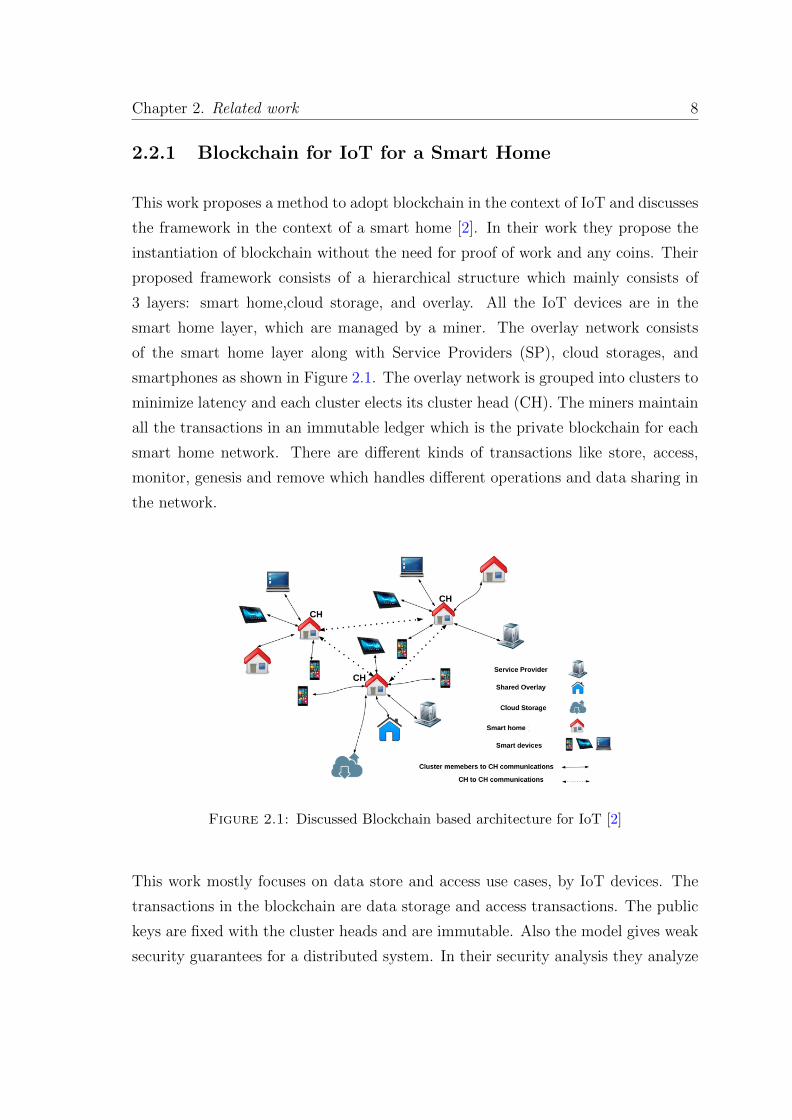
This work proposes a method to adopt blockchain in the context of IoT and discusses
the framework in the context of a smart home [2]. In their work they propose the
instantiation of blockchain without the need for proof of work and any coins. Their
proposed framework consists of a hierarchical structure which mainly consists of
3 layers: smart home,cloud storage, and overlay. All the IoT devices are in the
smart home layer, which are managed by a miner. The overlay network consists
of the smart home layer along with Service Providers (SP), cloud storages, and
smartphones as shown in Figure 2.1. The overlay network is grouped into clusters to
minimize latency and each cluster elects its cluster head (CH). The miners maintain
all the transactions in an immutable ledger which is the private blockchain for each
smart home network. There are different kinds of transactions like store, access,
monitor, genesis and remove which handles different operations and data sharing in
the network.
Figure 2.1: Discussed Blockchain based architecture for IoT [2]
This work mostly focuses on data store and access use cases, by IoT devices. The
transactions in the blockchain are data storage and access transactions. The public
keys are fixed with the cluster heads and are immutable. Also the model gives weak
security guarantees for a distributed system. In their security analysis they analyze
Chapter 2. Related work 9
their model for DDOS attack and linking attack. They also measure the overhead
for using their model over traditional message exchange.
2.2.2 Smart Contracts for IoT
The authors in this work describe the potential uses of blockchain with IoT devices
[18]. They describe scenarios for decentralized working of IoT devices with the
help of blockchains. Instead of a centralized deployment of firmware updates they
describe a smart contract based peer-to-peer mechanism for update of firmware. It
also uses the blockchains’ use of cryptocurrency to add a convenient business and
billing layer to the already existing network of devices. It describes the use of smart-
contracts and the Ethereum blockchain in the working of renting a smart lock for a
house [19]. It also describes the use of IoT and blockchain in the efficient use and
sharing of energy in the energy sector. It also describes a scenario for the use of IoT
and blockchain in supply chain management.
2.2.3 Virtual IoT resources on Edge Hosts with Blockchain
This work describes a method for hosting and distributing virtual resources and ap-
plications on IoT devices with the help of blockchains [20]. In this all the end device
applications and virtual resources are kept in a permissioned blockchain (multichain)
which are then deployed into the end devices. Code is pushed and updated on the
devices by using RESTful apis from blockchain.
2.2.4 IoT Electric business model
This work discusses a business model for IoT devices [21]. It proposes an architecture
to facilitate e-business with IoT devices with the help of blockchains and smart
contracts. It introduces the concept of IoTcoin, a parallel of bitcoin, for the purpose
of enabling e-business among IoT devices using smart-contracts.
Chapter 2. Related work 10
2.3 IoT Public key encryption
As IoT devices have both memory and processing power constraint so normal public
key encryption algorithms will incur huge latency and is not a feasible solution. So
there have been lots of research for implementing optimized public key encryption
algorithms for IoT. All public key encryption discussed to be used in later chapters
are one form of the optimized Elliptic Curve Cryptography (ECC) encryption. There
are different libraries which implement different optimized cryptographic protocols
for IoT devices [22]. Some of them are as follows:
2.3.1 WolfSSL
This library is written in ANSI C and has very low memory footprint. It allows
generation of keys and certificates and supports lots of cryptography algorithms. Its
runtime memory usage is very low and it has very simple api to use.
2.3.2 AvrCryptoLib
This library has the implementation of algorithms optimized for AVR 8-bit micro-
controllers. Besides supporting a wide range of algorithms it also supports MAC
functions and Pseudo Random Number Generators. It optimizes the execution time
by performing modular exponentiation in 8-bit assembly language. It also allows
direct access to keys by storing them in flash memory.
2.3.3 WiseLib
It is written in C++ and is mainly written for connected devices (devices connected
to some network). It can be easily used in various platforms like Contiki, iSense,
Shawn etc. It implements elliptic curve over prime fields only and in order to make
platform independent loses over the assembly level performance optimization.
Chapter 2. Related work 11
2.3.4 TinyECC
It is an Elliptic Curve Cryptography library which can be used to perform ECC-
based public key operations. It is mainly implemented for devices running TinyOS
however parts of its code can be altered to be used with other OSes as well.
2.3.5 RelicToolKit
It is a flexible and efficient toolkit which can be used for constructing custom crypto-
graphic toolkit. It also supports ECC-based algorithms. It supports customization
for inclusion of required components in desired platform and selecting desired math-
ematical optimization for optimum performance in the desired platform.

Chapter 3
Overall Architecture of Proposed
Model
We describe three different architectures which have different properties and func-
tionalities. Also the threats and possible attack vectors are different for each of
them. However the major component driving the architectures is the blockchain
technology which is the backbone for all the digital currencies like bitcoin, dogecoin,
namecoin etc [23].
3.1 Blockchains
Blockchain is a distributed database that maintains a continuously growing list of
records that is organized into entities called blocks. Blockchain, as the name sug-
gests, is a chain of these blocks with each block connected to its previous one by a
hash of the previous block.
3.1.1 History
The concept of blockchains dates back to the 90s which was just a variant of dis-
tributed database but the concept got traction in 2008 after the global financial
meltdown, when an anonymous person pseudo-named Satoshi Nakamoto published
13
Chapter 3. Overall Architecture of Proposed Model 14
a white paper for a type of digital currency from which bitcoin was born [23]. Orig-
inally in the paper, Nakamoto used the words block and chain separately but even-
tually on wider use the term became a single word blockchain [24]. The sole purpose
of blockchains is to facilitate secure online transactions which are publicly verifiable.
3.1.2 Principle of Blockchain
The main principle of a blockchain is that it maintains a distributed and decentral-
ized ledger of records across multiple computers so that a record can not be altered
without the alteration of all subsequent blocks or collusion of all nodes of the net-
work [25]. All the nodes maintaining the blockchain needs to reach a consensus on
the state of the blockchain. Blockchains can be classified into two types based on
the nature of the participants in the consensus protocol.
1. Public Blockchains : Public blockchains are open and permissionless, where
anybody can join the network and participate in the consensus protocol without
requiring the permission or trust of other nodes in the network. The consensus
protocols used in public blockchains are more complicated than those used in private
blockchains [24]. Some of the popular consensus protocols are Proof of Work (POW),
Proof of Stake (POS), Proof of Activity (POA), Proof of Burn (POB) etc [26].
2. Private Blockchains : Private blockchains are permissioned blockchains, where
each node knows and trusts every other node and any new node to be added to the
network needs to be allowed by majority nodes in the network. As every node is
added to the network, after validation the consensus protocols in the network are
relatively simpler [24].
3.1.3 Advantages
The prime advantages that a blockchain provides are as follows:
I. Public : The greatest advantage of blockchain is that it is public. Everyone can
see and verify its contents and also monitor the changes and updates made to it.
Chapter 3. Overall Architecture of Proposed Model 15
II. Decentralized : In blockchains there is no single authority to approve or dis-
approve new transactions. The nodes in the network must reach a consensus for
any transaction to be approved. Hence the trust of the network remains distributed
among the participating nodes.
III. Secure : The way the blocks are arranged in a blockchain makes it secure as it
becomes very hard computationally to modify multiple blocks in the blockchain.
3.1.4 Block
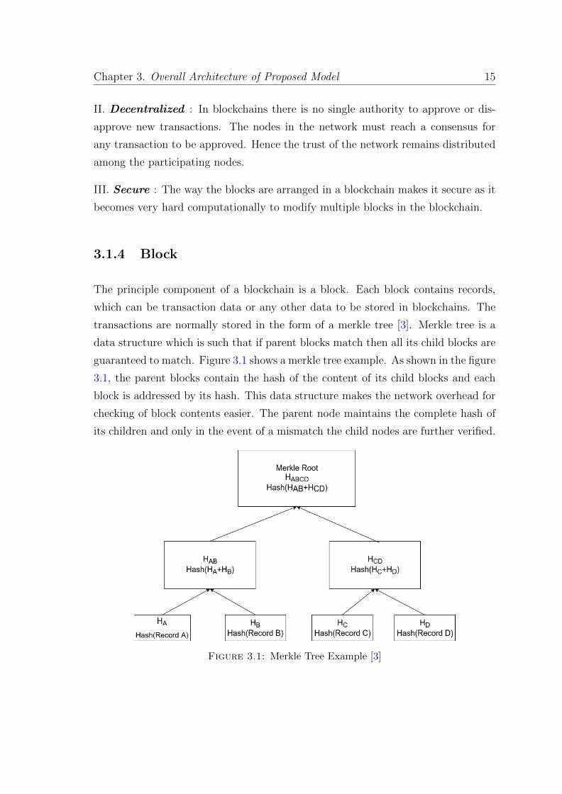
The principle component of a blockchain is a block. Each block contains records,
which can be transaction data or any other data to be stored in blockchains. The
transactions are normally stored in the form of a merkle tree [3]. Merkle tree is a
data structure which is such that if parent blocks match then all its child blocks are
guaranteed to match. Figure 3.1 shows a merkle tree example. As shown in the figure
3.1, the parent blocks contain the hash of the content of its child blocks and each
block is addressed by its hash. This data structure makes the network overhead for
checking of block contents easier. The parent node maintains the complete hash of
its children and only in the event of a mismatch the child nodes are further verified.
Figure 3.1: Merkle Tree Example [3]
Chapter 3. Overall Architecture of Proposed Model 16
The hash of previous parent block is included in the child block so that each block
is made cryptographically secure and it remains hard to modify the blocks in the
blockchain making them immutable.
3.1.4.1 Structure
The structure of a block varies and depends hugely on the use-case of the blockchain.
The generic structure is that a block starts with the hash of the parent block and
then there are contents. Each block in the chain is identified by its hash. Also
maintaining the hash of the parent block at the beginning of the block makes the
block immutable as in order to change any content of the blockchain one has to
change the entire chain as the hash of a block will change if any of its content
changes.
3.1.5 Consensus Protocol
The crux and the basic trust mechanism of any distributed system and hence the
blockchain also is its consensus protocol. Every participant of any distributed sys-
tem needs to agree on the same state of the whole system maintained by all the
peers. The process through which the participants in a distributed system comes
to an agreement for a common state of the system is called a consensus protocol.
For private blockchain, the protocol is simple as every participant is trusted and
hence they can come to a consensus through some gossip protocol or other simple
peer-to-peer messaging. However public blockchain needs some different consensus
protocols as anyone can join the network and as the nodes can be anonymous about
their identity, by joining with multiple anonymous identity anyone can influence the
network in favor of its own interests. A completely open network becomes prone to
the Sybil attack without a robust consensus protocol [27]. For public blockchain, the
consensus protocol decides which participant will add the new block to the chain.
Some of the popular consensus protocols are as follows:
• Proof of Work: Proof of Work asks for the computation power from the
participants. So the participating miner has to solve a computational problem
Chapter 3. Overall Architecture of Proposed Model 17
which is hard to solve but very easy to verify. This way the miner has to spend
some computational power in order to add a block.
• Proof of Stake: By this protocol a participant gets to add that much amount
of blocks to the network as much stake he holds in the network. For example
in a money network, a participant adds the percentage of transactions to the
network as much percentage of total value of the network he owns.
• Proof of Activity: It is an extension of the proof of work using the proof
of stake. After the computational problem is solved, some miners are chosen
based on an algorithm to sign the block and add it to the chain.
• Proof of Burn: In this protocol a miner gets the right to mine a block by
burning some assets (generally coins). By sacrificing his own assets he gets
the rights to add blocks to the blockchain.
3.1.6 Challenges for using existing bitcoin solution in IoT
Most of the adopted blockchain solutions are forks of the main bitcoin-core code-
base. However the major challenges of adopting the general bitcoin-core for the IoT
scenario are as follows:
• Computational Power: IoT devices are extremely small devices with limited
computational capability. Hence the computational power required for proof
of work is not feasible at all. Even the computation required for public key
encryption and decryption needs to be optimized in order to make it work for
IoT devices.
• Memory: IoT devices are also memory-constrained. So computations requir-
ing too much memory are not feasible.
• Storage: Blockchains require large amount of storage space to store the data.
IoT devices are tiny devices and do not have much storage space to store the
data.
Chapter 3. Overall Architecture of Proposed Model 18
3.2 Proposed Architecture for using PKI in IoT
There can be multiple models for using blockchains to store and deploy public keys
of IoT devices. We discuss three models of architectures of achieving it and discuss
their advantages and disadvantages. By discussing the different models we shift from
a completely centralized model to a completely decentralized model. Also in all the
models we use IPv6 for the sake of communication among various entities of the
network. IPv4 can’t be used as the address space of it is already getting exhausted
and the number of IoT devices would be too large for IPv4 to incorporate. Also
using the existing IPv6 allows the architectures to be integrated easily in to the
existing Internet infrastructure.
3.2.1 Private Permissioned Blockchain and Validators
This model works much like the current workflow for the use of public key in the
internet today. In this model there is a Central Certifying Authority (CCA) which is
considered to be fully secure. This model contains a central chain of validators who
are considered as miners. The blockchain is maintained only by these validators.
These validators will be the nodes maintained by different IoT device manufacturers
and are considered to have enough computational power and storage. These cen-
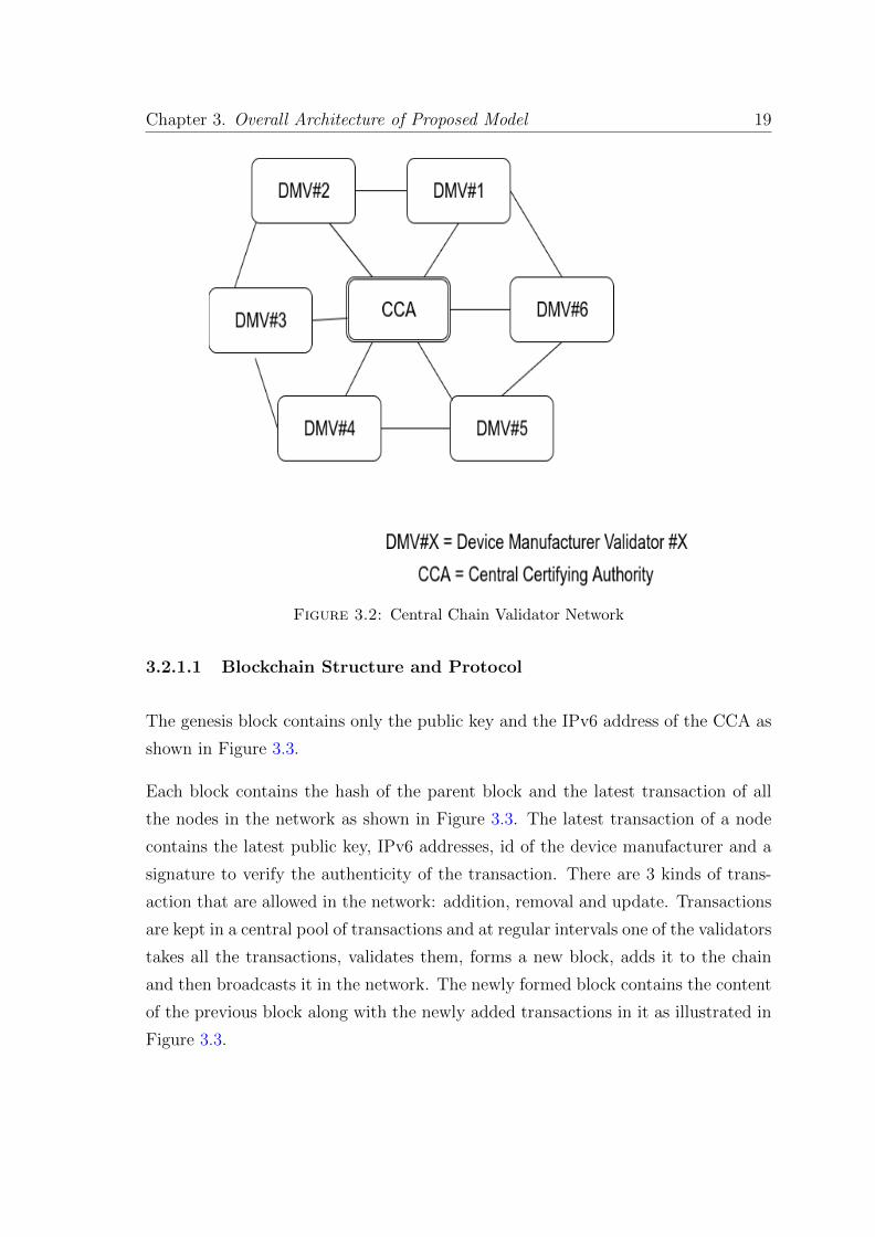
tral chain of validators are only added after proper verification by the CCA. Figure
3.2 shows the central validator network where each Device Manufacturer Validator
(DMV) are connected to each other and also connected to the CCA which is the
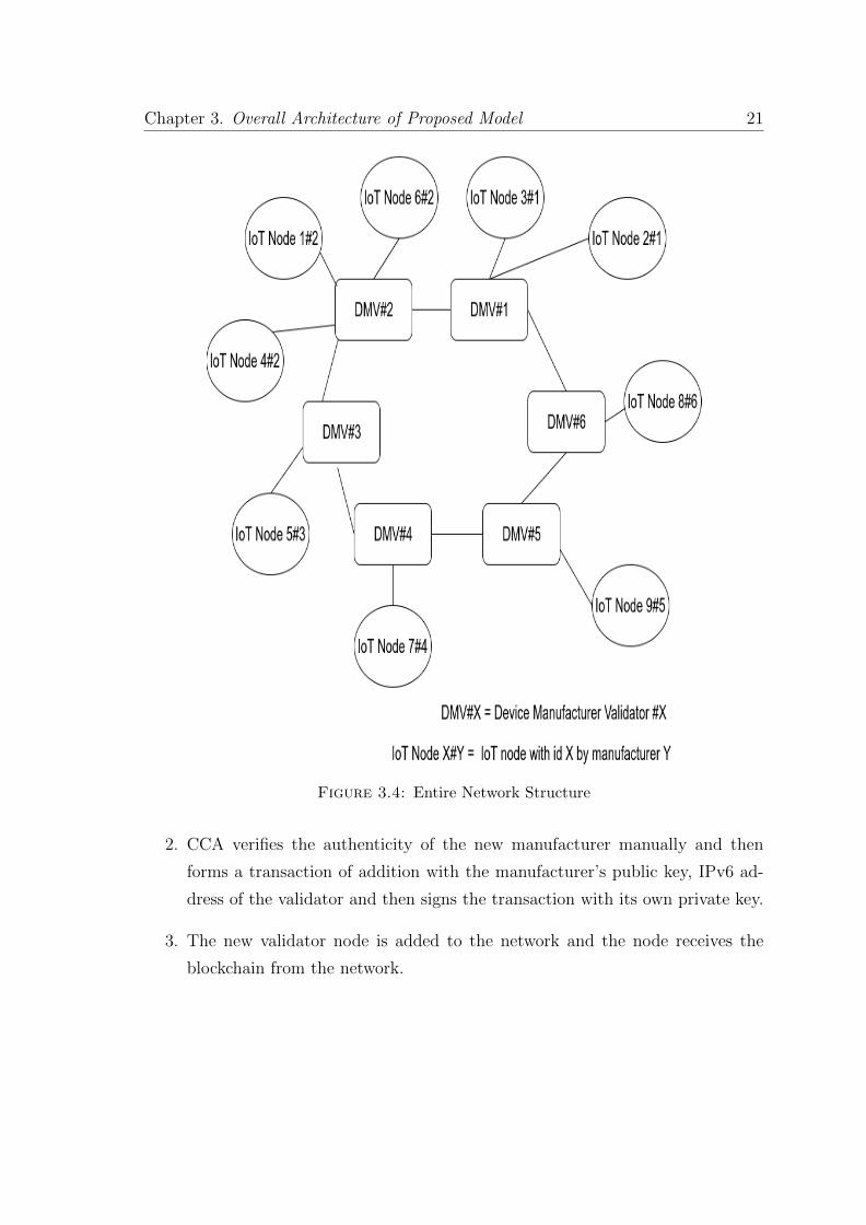
central authority. Figure 3.4 illustrates the entire network where the IoT nodes are
connected to the central validator network. In the Figure 3.4 each IoT node is con-
nected to the validator of its own manufacturer. In Figure 3.4 IoT Node X#Y means
the IoT device with id X manufactured by manufacturer with manufacturer id Y and
DMV#X means Device Manufacturer Validator of manufacture with manufacturer
id X. For sake of simplicity the central CCA is not shown in Figure 3.4.
Chapter 3. Overall Architecture of Proposed Model 19
Figure 3.2: Central Chain Validator Network
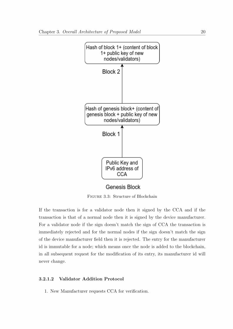
3.2.1.1 Blockchain Structure and Protocol
The genesis block contains only the public key and the IPv6 address of the CCA as
shown in Figure 3.3.
Each block contains the hash of the parent block and the latest transaction of all
the nodes in the network as shown in Figure 3.3. The latest transaction of a node
contains the latest public key, IPv6 addresses, id of the device manufacturer and a
signature to verify the authenticity of the transaction. There are 3 kinds of trans-
action that are allowed in the network: addition, removal and update. Transactions
are kept in a central pool of transactions and at regular intervals one of the validators
takes all the transactions, validates them, forms a new block, adds it to the chain
and then broadcasts it in the network. The newly formed block contains the content
of the previous block along with the newly added transactions in it as illustrated in
Figure 3.3.
Chapter 3. Overall Architecture of Proposed Model 20
Figure 3.3: Structure of Blockchain
If the transaction is for a validator node then it signed by the CCA and if the
transaction is that of a normal node then it is signed by the device manufacturer.
For a validator node if the sign doesn’t match the sign of CCA the transaction is
immediately rejected and for the normal nodes if the sign doesn’t match the sign
of the device manufacturer field then it is rejected. The entry for the manufacturer
id is immutable for a node; which means once the node is added to the blockchain,
in all subsequent request for the modification of its entry, its manufacturer id will
never change.
3.2.1.2 Validator Addition Protocol
1. New Manufacturer requests CCA for verification.
Chapter 3. Overall Architecture of Proposed Model 21
Figure 3.4: Entire Network Structure
2. CCA verifies the authenticity of the new manufacturer manually and then
forms a transaction of addition with the manufacturer’s public key, IPv6 ad-
dress of the validator and then signs the transaction with its own private key.
3. The new validator node is added to the network and the node receives the
blockchain from the network.
Chapter 3. Overall Architecture of Proposed Model 22
3.2.1.3 Node Addition Protocol
1. The manufacturer generates a public-private key-pair for the device and then
puts the private key in the device.
2. The manufacturer then forms a new transaction of addition with the device
id, the public key, the device IPv6 address, its own id as manufacturer id and
then signs the entire transaction using its private key. As the manufacturer
itself adds the manufacturer id in the transaction and signs it and once it is
added it can not be changed anytime, so the manufacturer id is not spoofable.
3. The node forming the block verifies the signature and then adds the block.
Threat Models
• Manufacturer Id Spoof: Someone tries to spoof the device manufacturer
id as somebody else. In this scenario the attacker would not have the private
key of the manufacturer he is spoofing and hence the sign would not match.
• Public Key Spoof: If the device manufacturer tries to put in a wrong public
key then other devices would not be able to communicate with this device and
it will hurt the reputation of the manufacturer.
• IPv6 Spoof: This scenario is the same as the above case and hence will not
occur.
3.2.1.4 Validator Update Protocol
1. In case of a compromised validator its public key is revoked by the CCA. The
CCA forms a new transaction of removal of the public key of the validator and
then signs the transaction.
2. The validator needs to go through the entire process of verification again in
order to update its public key.
3. On update of the public key of the validator, the manufacturer forms new
transactions to update the signature for all its devices.
Chapter 3. Overall Architecture of Proposed Model 23
There is no automated process for the CCA to detect a malicious validator. It is
done by manual reporting by other validators and manual verification by the CCA.
The CCA can also use an nomaly detector to detect malicious validators.
3.2.1.5 Node Update Protocol
1. In case a node requests to update its public key or IPv6 address then the node
requests the manufacturer with the update and the manufacturer then forms
a transaction of update and then signs it.
2. In case a node is compromised then the manufacturer revokes its key by forming
a transaction of removal and signs it.
3. When the access of the node is regained then the node asks for the public key
of its manufacturer from the blockchain. Then the node sends its new public
key and IPv6 address by encrypting them with the manufacturer’s public key
which the manufacturer forms as a transaction of update and then signs it.
4. Any update request can only have request for update of any 1 entry, either
public key or the IPv6. Request for update of both at once will be rejected by
the validator.
5. In case of public-key update, IP address can be spoofed. In order to remove
IP spoofing, a challenge-response system is used discussed later.
Threat Models
• Update Attack 1: Malicious Node A claims to be Node B and asks its
public-key to be updated to the manufacturer. However as it will come from
different IPv6 address than that is registered as its IPv6 address so the request
will be rejected.
• Update Attack 2: In the previous attack Node A can use IP spoofing and
make the update happen. IP spoofing can be mitigated by using a challenge-
response system. After the initial request, validator sends a challenge, which
needs to be encrypted using with the private key, to that IP address and only
Chapter 3. Overall Architecture of Proposed Model 24
on getting the correct response, the update is done. As malicious node A won’t
get the challenge (it’s IP address is different), the update won’t go through.
• Update Attack 3: Malicious Node A asks for the update of the IPv6 address
of Node B with its own IPv6 address. However as the message would not be
signed by the private key of original node B and thus it will be rejected.
• Update Attack 4: A man in the middle (MITM) intercepts the update
request and tries to change it but as the request is encrypted using the public
key of the manufacturer so he would not be able to change it.
The initial request for the public key of the manufacturer from the blockchain is
done using Diffie-Hellman Key exchange protocol as explained in Appendix A or
else it would be prone to man-in-the-middle attack.
The method for a manufacturer to detect malicious nodes can be by using some
anomaly detection techniques.
3.2.1.6 Node Communication Protocol
1. Node A requests the public key for the node B with which it wants to commu-
nicate from the validator. It encrypts the request with the validator’s public
key and signs it with its own private key.
2. The validator receives the request, checks its valiadity and checks the latest
block in the blockchain for the public key of node B. If the public key for the
node B is present in the block and it is valid then it sends the response by
signing it with its own private key and encrypting it with node A’s public key
which it can get from the blockchain. If the public key of node B is not present
or it marked invalid then it sends a null response to node A after signing and
encrypting it.
3. Node A receives the public key and IPv6 address for node B. Now it generates
a symmetric key which it signs with own private key and then encrypts with
node B’s public key and sends the message to node B.
Chapter 3. Overall Architecture of Proposed Model 25
4. Node B receives the message from node A and checks its validity. If it want’s
to communicate with node A then it sends message encrypted by encrypting
it with secret key established between these nodes.
5. The header of each message contains the type of encryption used in the mes-
sage.
Threat Models
• Man in the Middle Attack: As all the messages are sent in a encrypted way
so there can be no Man in the middle attack in the communication. However a
man-in-the-middle can intercept the messages and resend them later resulting
in a replay attack [28]. So in order to mitigate this attack, time-stamping is
used along with the messages.
• Denial of message: This model is vulnerable to a denial of message attack
where as the type of encryption is in the header so anyone in between can
intercept the message and change the type of encryption in the header field to
confuse the receiver to decrypt the message in a wrong way. This problem can
be avoided by trying the other method of encryption if one mode of decryption
fails to produce anything meaningful. The type of encryption in the header is
only to reduce double computation for every message.
3.2.1.7 Overall Threats
1. 51% Attack: As this model is a centralised model where there are verified
controllers so it is not vulnerable to the 51% attack threat as any malicious
validator will only affect the working of the manufacturer’s own devices and
not anybody else.
2. Man in the middle attacks: As all communications are encrypted so there
can be no man-in-the-middle attack. Also time-stamping is used to mitigate
replay attacks.
3. Single point of failure: Huge trust is placed on the CCA. Hence compromise
of the CCA would result in the failure of the entire protocol.
Chapter 3. Overall Architecture of Proposed Model 26
4. DDOS Attack: Just like most networks here also the nodes are vulnerable to
DDOS attacks but it can be prevented by using a normal rate limiting firewall.
5. Insider Attack: In case of insider attack in the CCA, the entire network is
compromised as it is the single point of failure of the network.
3.2.2 Evolution of Internet 4.0
This model is inspired from the early decentralized rise of the internet by linking
computers together with each other. It is a more decentralized approach and involves
formation of clusters and merging of clusters into bigger clusters. The entire idea
is born out of a way of finding trust in a completely trustless environment. The
problem is how to trust the public key of a completely unknown node.
3.2.2.1 Paradox of Trust
The paradox of trust is like a chicken-egg problem. Trusting someone needs to know
that person very well. But in order to know a person the person needs to trust him.
This problem is discussed and handled in the context of prisoner’s dilemma problem
previously [29]. In order to reach a trust based consensus, there needs to be some
root of trust and some way of spreading trust among the network.
This model of architecture consists mainly of two different layers in it: The Personal
Area Network (PAN) and the Global Area Network (GAN). The entire point of
trust in this model stays with the device manufacturer. Instead of a already existing
central chain of validators and CCA, in this model the trust network grows slowly
and eventually to a bigger clusters. In this model the manufacturer becomes the
CCA for its own network.
3.2.2.2 Personal Area Network - PAN
The PAN consists of all the user-level devices and a gateway to communicate with
the global network. All the IoT device endpoints connected to a single gateway
constitute of a PAN. The devices and the gateway must be manufactured by the
Chapter 3. Overall Architecture of Proposed Model 27
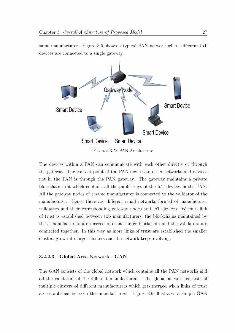
same manufacturer. Figure 3.5 shows a typical PAN network where different IoT
devices are connected to a single gateway.
Figure 3.5: PAN Architecture
The devices within a PAN can communicate with each other directly or through
the gateway. The contact point of the PAN devices to other networks and devices
not in the PAN is through the PAN gateway. The gateway maintains a private
blockchain in it which contains all the public keys of the IoT devices in the PAN.
All the gateway nodes of a same manufacturer is connected to the validator of the
manufacturer. Hence there are different small networks formed of manufacturer
validators and their corresponding gateway nodes and IoT devices. When a link
of trust is established between two manufacturers, the blockchains maintained by
these manufacturers are merged into one larger blockchain and the validators are
connected together. In this way as more links of trust are established the smaller
clusters grow into larger clusters and the network keeps evolving.
3.2.2.3 Global Area Network - GAN
The GAN consists of the global network which contains all the PAN networks and
all the validators of the different manufacturers. The global network consists of
multiple clusters of different manufacturers which gets merged when links of trust
are established between the manufacturers. Figure 3.6 illustrates a simple GAN
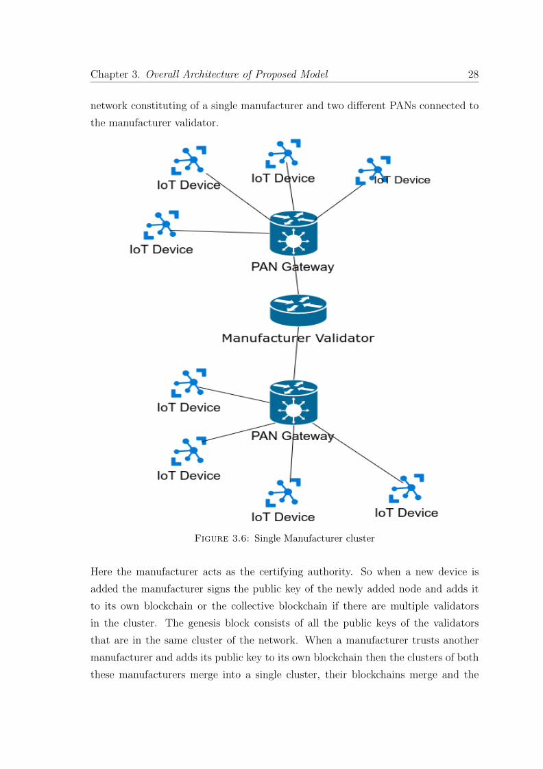
Chapter 3. Overall Architecture of Proposed Model 28
network constituting of a single manufacturer and two different PANs connected to
the manufacturer validator.
Figure 3.6: Single Manufacturer cluster
Here the manufacturer acts as the certifying authority. So when a new device is
added the manufacturer signs the public key of the newly added node and adds it
to its own blockchain or the collective blockchain if there are multiple validators
in the cluster. The genesis block consists of all the public keys of the validators
that are in the same cluster of the network. When a manufacturer trusts another
manufacturer and adds its public key to its own blockchain then the clusters of both
these manufacturers merge into a single cluster, their blockchains merge and the
Chapter 3. Overall Architecture of Proposed Model 29
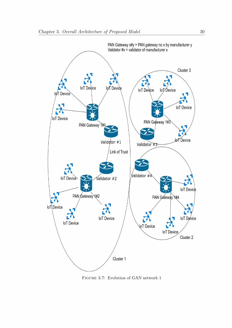
devices of each manufacturer can establish communication among each other. It
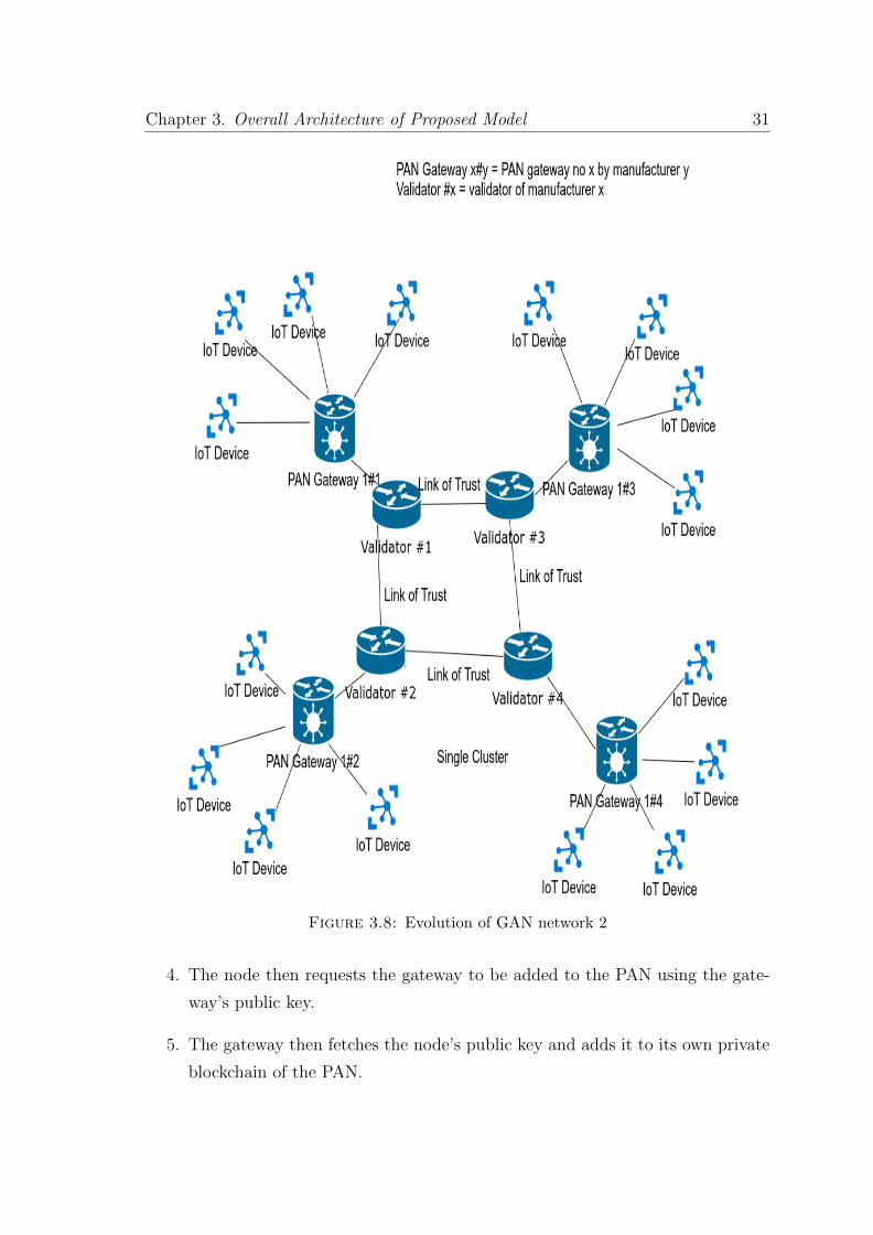
is a more decentralized model than the previous model. Figure 3.7 and Figure 3.8
illustrates this idea of merging of the clusters. In both the figures validator#X refers
to the validator by manufacturer X. PAN gateway X#Y refers PAN gateway no X
manufactured by manufacturer Y. Figure 3.7 illustrates the merge of manufacturer
1 and manufacturer 2 into a single cluster (cluster 1) and manufacturer 3 and 4
remaining in there own clusters (cluster 3 and 2 respectively). In Figure 3.8 all four
manufacturers are merged into a single cluster and so their validators are linked
together in a single network.
3.2.2.4 Block Addition Protocol
1. There are 3 kinds of transactions: Addition, Removal and Update.
2. There is a central pool of all the transactions for each cluster.
3. At regular intervals one of the validators from the cluster forms a block from
all the transactions in the pool, signs it and then broadcasts it in the network.
The interval of block formation can be fixed by the network protocol as per
requirements of the network.
4. The validator to add the block to the blockchain is decided in a round-robin
fashion.
5. In case of a single manufacturer in the cluster it forms the block at regular
intervals.
3.2.2.5 Node Addition Protocol
1. The manufacturer generates the private-key and public-key of the node and
store the private key in the node.
2. The manufacturer then forms a transaction of addition, signs the transaction
and adds it to the pool to be later added to a block.
3. When the node is added to a PAN then the node requests for the public key
of the gateway from the validator using Diffie-Hellman protocol as explained
in Appendix A.
Chapter 3. Overall Architecture of Proposed Model 30
Figure 3.7: Evolution of GAN network 1
Chapter 3. Overall Architecture of Proposed Model 31
Figure 3.8: Evolution of GAN network 2
4. The node then requests the gateway to be added to the PAN using the gate-
way’s public key.
5. The gateway then fetches the node’s public key and adds it to its own private
blockchain of the PAN.
Chapter 3. Overall Architecture of Proposed Model 32
3.2.2.6 Gateway Addition Protocol
1. The manufacturer generates the private-key and public-key of the gateway and
stores the private key in the gateway.
2. The manufacturer then forms a transaction of addition, signs the transaction
and adds it to the pool to be later added to a block.
3. When the gateway is deployed it just needs to connect to the validator directly.
3.2.2.7 Cluster Merge Protocol
1. Manufacturer A establishes a link of trust with manufacturer B. They exchange
their public keys through some other trusted methods like exchanging mails
or manual exchange.
2. Validator of manufacturer A forms a link with validator of manufacturer B.
Validator A forms a new transaction of addition, adds validator B’s public
key to it, signs it and adds it to its blockchain. Similarly Validator B adds
validator A’s public key to its blockchain.
3. Now validator A requests latest block from validator B. The request is sent by
encrypting with validator B’s public key.
4. Now validator A forms a new block which contains the content of its latest
block and the latest block of validator B and adds it to the blockchain and
then broadcasts it in the network.
5. Now both validators maintain a single blockchain and new blocks are added
to this chain.
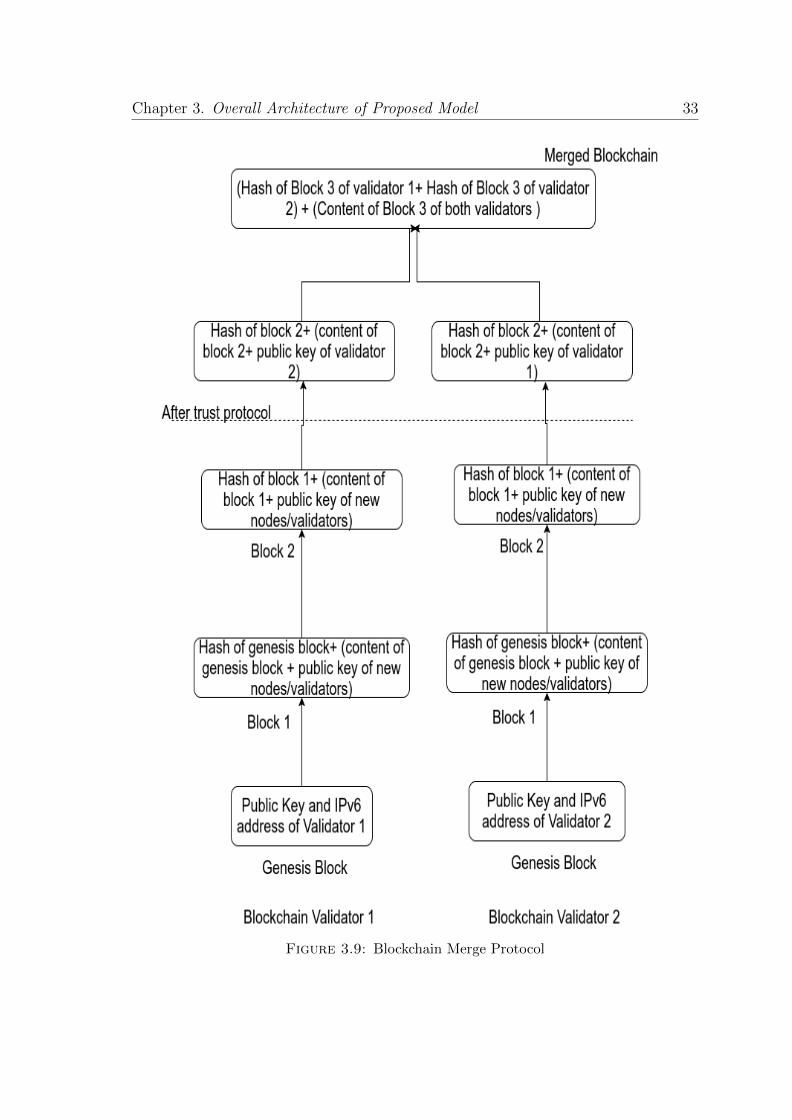
Figure 3.9 illustrates the merging procedure of two blockchains into a single blockchain.
As shown in the figure, before trust was established between the validators both val-
idators maintained their own separate blockchains. After the link of trust is estab-
lished, validator 1 adds validator 2’s public key to its own blockchain after signing
it properly and vice-versa as shown in Figure 3.9. After that a block is formed with
content of the latest block of both blockchains and so the blockchains merge into a
single blockchain as shown in Figure 3.9.
Chapter 3. Overall Architecture of Proposed Model 33
Figure 3.9: Blockchain Merge Protocol
Chapter 3. Overall Architecture of Proposed Model 34
3.2.2.8 Node/Gateway Update Protocol
1. The node/gateway requests the validator for the update of its IPv6 address/pub-
lic key. Changing of both the values at once is forbidden.
2. In case of public-key update the request has to be sent from the IPv6 address
of the node/gateway in the blockchain. IP address spoofing in this case can be
mitigated by using a challenge-response system as discussed in Section 3.2.1.5.
3. In case of a IPv6 update the request needs to be sent after signing with the
node’s private key.
4. The validator then forms a transaction of update and then signs it and adds
it to the pool.
5. In case the update is of node the updated record is sent to the gateway of the
PAN the node is in. The PAN gateway updates its own private blockchain
with the record.
6. In case the update is of a gateway, the validator sends the update to all the
nodes in the PAN of the gateway so that they can communicate with the
gateway.
3.2.2.9 Node Removal Protocol
1. In case a node/gateway needs to be removed the validator forms a transaction
of removal, signs it and adds it to the pool.
3.2.2.10 Validator Removal Protocol
1. In case a validator is compromised, one of the uncompromised validators forms
a transaction of removal for the validator and adds it to the blockchain.
2. The validator is removed from the central network. All public keys signed by
the validator after the last update of its own public key are revoked.
Chapter 3. Overall Architecture of Proposed Model 35
3. A new block is formed which consists of all these public keys and the validator’s
public key marked as invalid and the new block is broadcast in the network
and added to the blockchain.
The way a validator is deemed compromised is when majority of the validators find
a validator rogue (validator is adding malicious nodes in the network).
3.2.2.11 Node Communication Protocol
1. Node A requests for public key of node B with which it wishes to establish
communication from the gateway.
2. The gateway looks for the public key in its own private blockchain. If it finds
a valid key it means the other node is in the same PAN. If it couldn’t find the
key it means the device is in some other PAN. It requests for the public key
from the validator node.
3. It sends the public key by signing it to the node. If the other node is in the
same PAN then node A sends a symmetric key to node B after signing it and
encrypting it.
4. If node B wishes to communicate it asks for the public key of node A from the
gateway and checks the validity of the message and starts the communication
using the symmetric key.
5. If node B is in some other PAN the node A signs and encrypts the symmetric
key and sends it to its own gateway. The gateway asks for the public key of
the gateway of node B. It then establishes a communication channel with the
gateway of node B and forwards the packet of node A to the other gateway
after itself signing it and encrypting it. The other gateway then sends the
packet to node B and a communication channel is established between the
nodes. All further communications from node A to node B happen through
the gateways of the respective nodes.
Chapter 3. Overall Architecture of Proposed Model 36
3.2.2.12 Threat Models
1. 51% Attack It is vulnerable to compromise if 51% of the validators in a cluster
are compromised as the root of trust remains with the validators themselves.
2. Man in the middle attacks: As all communications are encrypted so there
can be no man-in-the-middle attack. Time-stamping is used in order to miti-
gate replay attacks.
3. Point of failure: Instead of single point of failure as in previous model, the
point of failure shifts to the validators and in case of compromise of a validator,
all devices of that manufacturer is compromised. Also as the rogue validator
can easily add rogue devices in the network, it can add the entries of the rogue
devices in the blockchain and as the other validators trust the rogue validator,
so the entire network is compromised.
4. Insider Attack: In case of insider attack in any manufacturer, the key of a
manufacturer can get compromised. So when the validator of the manufacturer
gets rogue, the entire network is compromised.
3.2.3 Final Model: PUF based Architecture
The final model is a fully decentralized model for the communication of IoT devices
using blockchains. It removes any central authority similar to namecoin [30] and
certcoin [31] and is based on identifying devices uniquely through their IDs. It
requires the devices to have Physical Unclonable Function (PUF) [32] capability
which may be hard to guarantee in all IoT devices. Although having a PUF may
guarantee tighter security benefits but this necessity can be relaxed by having a
secure memory location in all devices. The PUF is only required for the generation
of public key pair whose private key is not kept anywhere but it is calculated on the
fly in a trusted zone when required. This requirement can be relaxed if the devices
have a trusted memory location to store the generated secret key.
Chapter 3. Overall Architecture of Proposed Model 37
3.2.3.1 Device Requirements
In order to guarantee security requirements the devices need to have the following
properties:
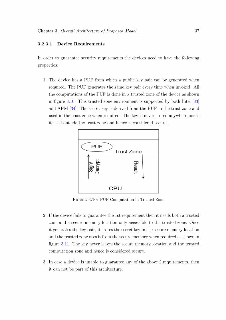
1. The device has a PUF from which a public key pair can be generated when
required. The PUF generates the same key pair every time when invoked. All
the computations of the PUF is done in a trusted zone of the device as shown
in figure 3.10. This trusted zone environment is supported by both Intel [33]
and ARM [34]. The secret key is derived from the PUF in the trust zone and
used in the trust zone when required. The key is never stored anywhere nor is
it used outside the trust zone and hence is considered secure.
Figure 3.10: PUF Computation in Trusted Zone
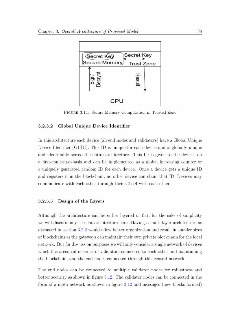
2. If the device fails to guarantee the 1st requirement then it needs both a trusted
zone and a secure memory location only accessible to the trusted zone. Once
it generates the key pair, it stores the secret key in the secure memory location
and the trusted zone uses it from the secure memory when required as shown in
figure 3.11. The key never leaves the secure memory location and the trusted
computation zone and hence is considered secure.
3. In case a device is unable to guarantee any of the above 2 requirements, then
it can not be part of this architecture.
Chapter 3. Overall Architecture of Proposed Model 38
Figure 3.11: Secure Memory Computation in Trusted Zone
3.2.3.2 Global Unique Device Identifier
In this architecture each device (all end nodes and validators) have a Global Unique
Device Identifier (GUDI). This ID is unique for each device and is globally unique
and identifiable across the entire architecture. This ID is given to the devices on
a first-come-first-basis and can be implemented as a global increasing counter or
a uniquely generated random ID for each device. Once a device gets a unique ID
and registers it in the blockchain, no other device can claim that ID. Devices may
communicate with each other through their GUDI with each other.
3.2.3.3 Design of the Layers
Although the architecture can be either layered or flat, for the sake of simplicity
we will discuss only the flat architecture here. Having a multi-layer architecture as
discussed in section 3.2.2 would allow better organization and result in smaller sizes
of blockchains as the gateways can maintain their own private blockchain for the local
network. But for discussion purposes we will only consider a single network of devices
which has a central network of validators connected to each other and maintaining
the blockchain, and the end nodes connected through this central network.
The end nodes can be connected to multiple validator nodes for robustness and
better security as shown in figure 3.12. The validator nodes can be connected in the
form of a mesh network as shown in figure 3.12 and messages (new blocks formed)
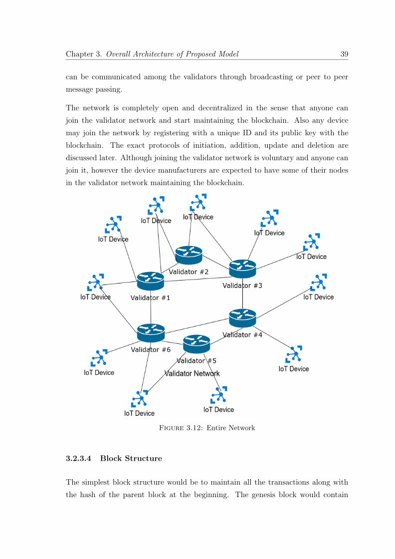
Chapter 3. Overall Architecture of Proposed Model 39
can be communicated among the validators through broadcasting or peer to peer
message passing.
The network is completely open and decentralized in the sense that anyone can
join the validator network and start maintaining the blockchain. Also any device
may join the network by registering with a unique ID and its public key with the
blockchain. The exact protocols of initiation, addition, update and deletion are
discussed later. Although joining the validator network is voluntary and anyone can
join it, however the device manufacturers are expected to have some of their nodes
in the validator network maintaining the blockchain.
Figure 3.12: Entire Network
3.2.3.4 Block Structure
The simplest block structure would be to maintain all the transactions along with
the hash of the parent block at the beginning. The genesis block would contain
Chapter 3. Overall Architecture of Proposed Model 40
only the transaction of the initiation of the record of the node starting the network.
Each transaction would contain the following fields: the GUDI of the node, the
IPv6 address of the node, the public key of the node, the type of the transaction
and the signature of the transaction. Each transaction is self-signed by the device
generating the transaction. There is no involvement of the manufacturer in signing
the transactions in this architecture.
A more efficient storage method of the transactions would be to store all the trans-
actions in a merkle tree, discussed in section 3.1.4, at some central location and
then storing the state of the merkle tree in the new block. In this method there
can be some central storage, which contains the merkle tree, maintained by all the
validators thus saving space for all the validators. On addition of new transactions,
the transactions are added to the merkle tree and the updated state of the tree is
stored in the new block and added to the blockchain. This central storing of the
merkle tree is just an optimization technique that can be used by the validators to
reduce the space requirement. Multiple validators can have a single central storage
to maintain the merkle tree together and save space.
3.2.3.5 Device Keys
Each device in the network maintain 2 sets of keys. One set of keys is used for all
the communication with other devices which is the ”Use Key (UK)”. The other set
of keys is used for signing all the addition and update of the transactions in the
blockchain which is the ”Signing Key (SK)”. The Use Key can be stored in normal
memory, but the Signing Key needs to be formed either from the PUF or stored in
the secure memory location in the trust zone as discussed in section 3.2.3.1. The
Signing Key is the root of trust for the device and compromise of it would leave the
device useless.
3.2.3.6 Node/Validator Addition Protocol
1. The node gets a new GUDI for itself. In case of a increasing global counter,
the node checks the current state of the counter and gets its corresponding
GUDI. In case of random generated GUDI, the node generates a random ID,
Chapter 3. Overall Architecture of Proposed Model 41
checks for its existence in the current blockchain and if not present uses it, else
it keeps on generating new IDs until it finds one which is unused.
2. The Signing Key’s public key is retrieved from the PUF or a key pair is gen-
erated and the secret key is stored in the secure memory location, in case of
absence of PUF.
3. The node forms a new initiation transaction with its GUDI, IPv6 address and
the Signing Public Key (SPK) and then signs the transaction with its Signing
Secret Key (SSK) in the trust zone.
4. The validator adding the transaction to the blockchain verifies the signature
of the transaction and adds it to the new block if the signature is correct, else
it discards it.
5. After the initiation transaction is formed, the node generates the Use Key pair.
It then forms a transaction of addition with its GUDI, IPv6 address and the
Use Public Key (UPK) and then signs the transaction with its Signing Secret
Key.
6. The validator adding the transaction to the blockchain retrieves the Signing
Public Key of the node from the blockchain, verifies the signature of the trans-
action and if verified adds it to the blockchain, else it discards the transaction.
7. If the node is a validator, then it receives a copy of the blockchain from its
peers.
3.2.3.7 Node Update Protocol
1. The node can update both its IPv6 address and Use Public Key. In case
of compromise of the Use Secret Key (USK), the Use Public Key needs to be
updated. The GUDI and the SPK are fixed for a node and can not be updated.
2. The node forms a update transaction with the necessary changes and then
signs it with its SSK.
3. The validator adding the transaction to the blockchain will retrieve the SPK
of the node from the blockchain, verify the signature of the transaction and if
verified will add it to the blockchain, else will reject the transaction.
Chapter 3. Overall Architecture of Proposed Model 42
3.2.3.8 Node Deletion Protocol
1. The node who wants to revoke its UPK, due to its compromise or some reason,
forms a delete transaction and signs the transaction with its SSK.
2. The validator adding the transaction retrieves the SPK of the node, verifies
the signature of the transaction and if verified adds it to the blockchain. Else
it rejects the transaction.
3.2.3.9 Node Discovery
The previous models had implicit node discovery in them. In those architectures as
the addition of the nodes was done by the manufacturer, so each node was associated
with the manufacturer and the manufacturer can also add the type of the node in
the blockchain if required. If some node wanted to find some specific device of a
manufacturer, it could search the blockchain and get the corresponding record for
that device. However in this model nodes are only identified through their GUDI and
as nodes add themselves in the blockchain, there is no way to know the manufacturer
and type of the device correctly. So if a device wants to communicate with some
other device then it needs to get the GUDI of that device through some other method
like writing letters or exchanging mails.
3.2.3.10 Node Communication Protocol
Following is the workflow when device A wants to establish communication with
device B.
1. Device A gets the GUDI of the device B through some other method from
device B.
2. Device A asks for the record of device with GUDI of device B from one of the
validators maintaining the blockchain. The communication with the validator
is established using the Diffie-Hellman protocol as explained in Appendix A
to avoid MITM attacks.
Chapter 3. Overall Architecture of Proposed Model 43
3. The validator from which the record is asked fetches the record with cor-
responding GUDI from the blockchain. As the record was added in the
blockchain after verifying the signature, so verifying its content again is not
necessary. The validator sends the record to Device A.
4. Device A gets the public key and the IPv6 address of device B from the record
and sends a secret key, by encrypting it with the public key, to device B. If
device B wants to continue the communication, it responds with an acknowl-
edgement, else it does nothing.
3.2.3.11 Privacy and Anonymity
This model has the limitation of the absence of device discovery as discussed in Sec-
tion 3.2.3.9. However this limitation empowers it with the powerful tool of anonymity
and ensures privacy of the device. As the devices add themselves to the blockchain,
their privacy and anonymity is maintained in the network. As most IoT devices can
have critical information in it, privacy is an important part and this model provides
the required anonymity to the devices.
3.2.3.12 Some Threat Models
• 51% Attack This architecture is secure based on the honesty of the validator
nodes. The validator nodes need to verify the correctness of the new transac-
tions that are being added and reject them if the signature is not verified. So if
majority of nodes are honest, then only correct transactions will get added to
the blockchain. However if more than 51% of the validators are malicious and
they collude, then incorrect malicious transactions (transactions with wrong
public key and wrong signature) may get added to the blockchain resulting in
compromise of the whole network. Hence the network is vulnerable to 51%
collusion attack.
• Loss of Private Key In case the SK pair of a device is compromised, the
control of the device can not be regained without manual intervention.
Chapter 3. Overall Architecture of Proposed Model 44
• Point of Failure In the first model, the CCA was the single point of failure
and compromise of it would render the network compromised. In the second
model, the point of failure is the manufacturer validators. However in this
model, the point of failure is distributed among the devices, as authenticity of
each device is maintained entirely using its SK pair.
• Aging of PUF One of the problems with PUFs is that PUFs generally de-
teriorate with time. If a PUF deteriorates, then it won’t be able to produce
the same key pair and so it is equivalent to the loss of private key, and so the
device control is completely lost.
• Insider Attack: This model is not vulnerable to any insider attack as the
root of trust is with the devices itself.
Chapter 4
IoT Simulator in NS3
A simulator is an essential component for testing and validating new models and
architectures of any system. As testing new threat models is expensive to test on
real networks and devices, so NS3 simulator was formed. Network Simulator 3
(NS3) simulator was designed to be used for research purposes to test new protocols
and architecture [14]. NS3 has been actively developed by the community and
new modules are being actively developed and maintained by the community. NS3
simulator has support for most of the networking protocols and also supports most
types of networking devices. The different protocols generally used by IoT devices
like Bluetooth, LTE, Zigbee, 6LOWPAN are also supported in the simulator.
4.1 IoT Generator
IoT generator is extended from the NS3 topology generator [4]. It is visual inter-
face using QT4 to form a network topology of nodes/devices with applications and
connecting them using different protocols. Figure 4.1 shows an example topology of
devices formed using the generator. After the topology is formed it can then gener-
ate both C++ and python simulation source files for NS3 which can be run directly
in NS3 to get simulation results. The generator is built on the QT framework of
C++ and new types of nodes can be added to be generated by the generator. For
the IoT simulator we have added 3 kinds of devices namely IoT node, Blockchain
45
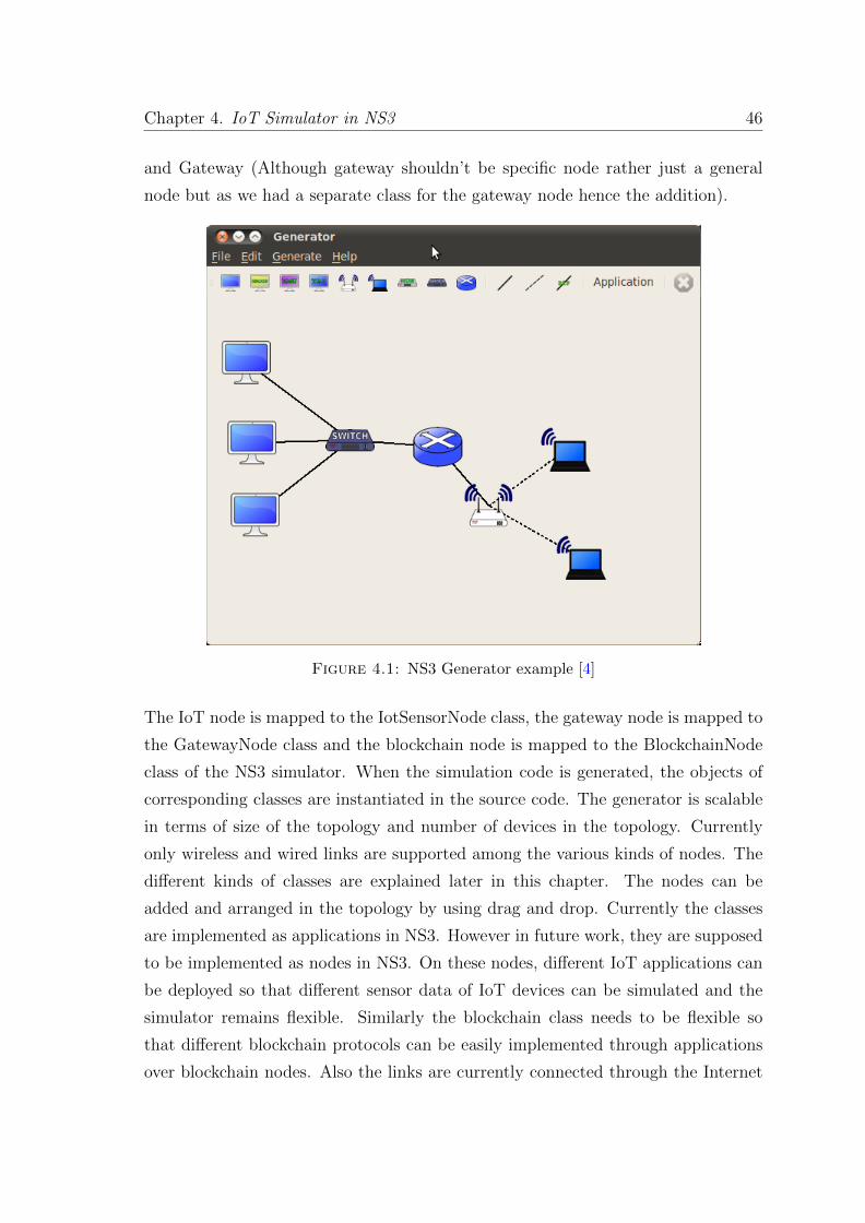
Chapter 4. IoT Simulator in NS3 46
and Gateway (Although gateway shouldn’t be specific node rather just a general
node but as we had a separate class for the gateway node hence the addition).
Figure 4.1: NS3 Generator example [4]
The IoT node is mapped to the IotSensorNode class, the gateway node is mapped to
the GatewayNode class and the blockchain node is mapped to the BlockchainNode
class of the NS3 simulator. When the simulation code is generated, the objects of
corresponding classes are instantiated in the source code. The generator is scalable
in terms of size of the topology and number of devices in the topology. Currently
only wireless and wired links are supported among the various kinds of nodes. The
different kinds of classes are explained later in this chapter. The nodes can be
added and arranged in the topology by using drag and drop. Currently the classes
are implemented as applications in NS3. However in future work, they are supposed
to be implemented as nodes in NS3. On these nodes, different IoT applications can
be deployed so that different sensor data of IoT devices can be simulated and the
simulator remains flexible. Similarly the blockchain class needs to be flexible so
that different blockchain protocols can be easily implemented through applications
over blockchain nodes. Also the links are currently connected through the Internet
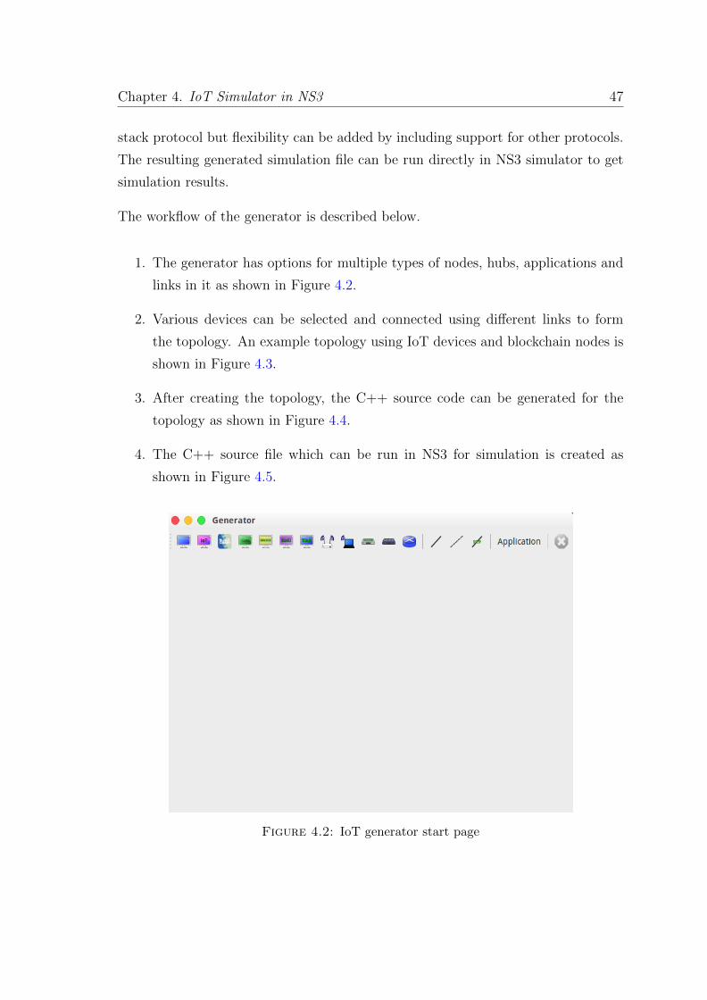
Chapter 4. IoT Simulator in NS3 47
stack protocol but flexibility can be added by including support for other protocols.
The resulting generated simulation file can be run directly in NS3 simulator to get
simulation results.
The workflow of the generator is described below.
1. The generator has options for multiple types of nodes, hubs, applications and
links in it as shown in Figure 4.2.
2. Various devices can be selected and connected using different links to form
the topology. An example topology using IoT devices and blockchain nodes is
shown in Figure 4.3.
3. After creating the topology, the C++ source code can be generated for the
topology as shown in Figure 4.4.
4. The C++ source file which can be run in NS3 for simulation is created as
shown in Figure 4.5.
Figure 4.2: IoT generator start page
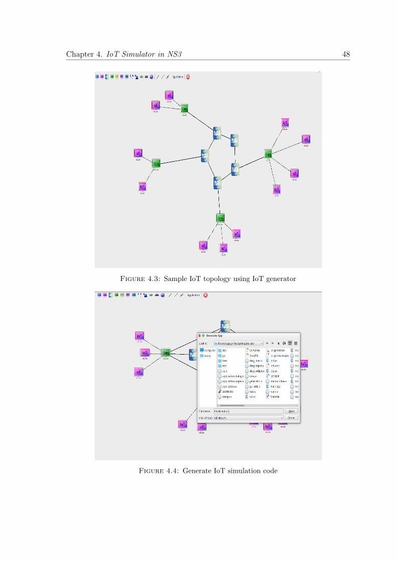
Chapter 4. IoT Simulator in NS3 48
Figure 4.3: Sample IoT topology using IoT generator
Figure 4.4: Generate IoT simulation code
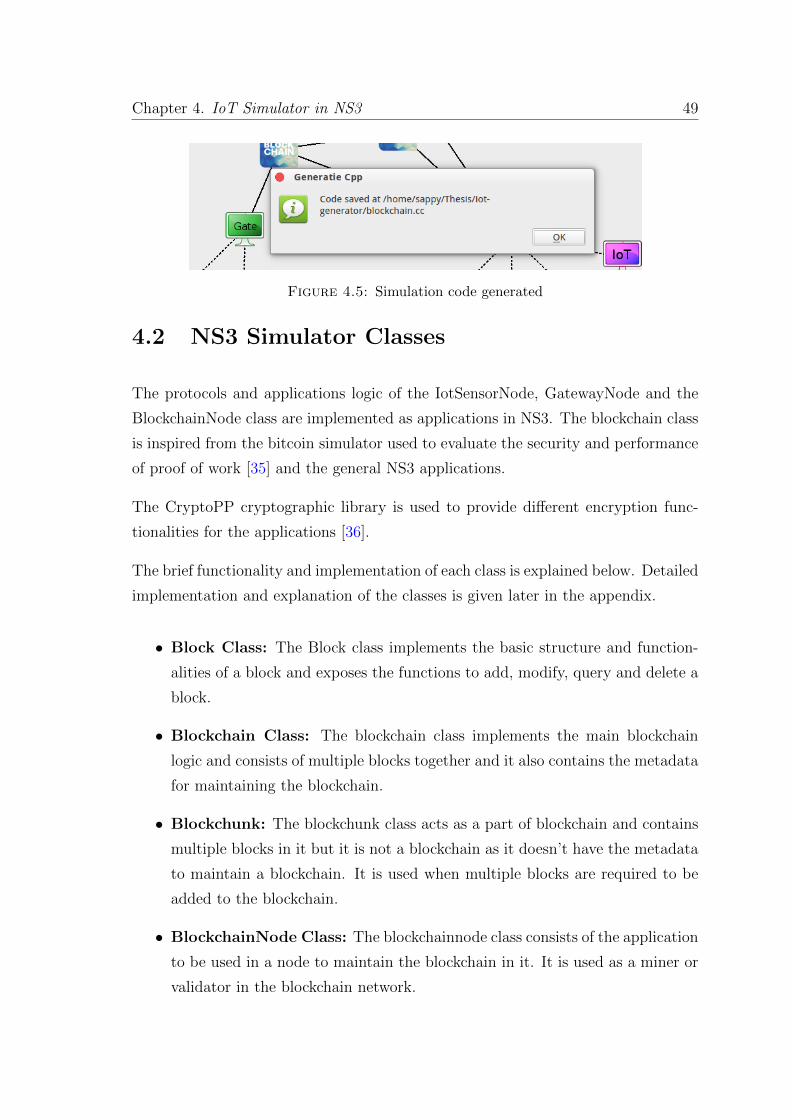
Chapter 4. IoT Simulator in NS3 49
Figure 4.5: Simulation code generated
4.2 NS3 Simulator Classes
The protocols and applications logic of the IotSensorNode, GatewayNode and the
BlockchainNode class are implemented as applications in NS3. The blockchain class
is inspired from the bitcoin simulator used to evaluate the security and performance
of proof of work [35] and the general NS3 applications.
The CryptoPP cryptographic library is used to provide different encryption func-
tionalities for the applications [36].
The brief functionality and implementation of each class is explained below. Detailed
implementation and explanation of the classes is given later in the appendix.
• Block Class: The Block class implements the basic structure and function-
alities of a block and exposes the functions to add, modify, query and delete a
block.
• Blockchain Class: The blockchain class implements the main blockchain
logic and consists of multiple blocks together and it also contains the metadata
for maintaining the blockchain.
• Blockchunk: The blockchunk class acts as a part of blockchain and contains
multiple blocks in it but it is not a blockchain as it doesn’t have the metadata
to maintain a blockchain. It is used when multiple blocks are required to be
added to the blockchain.
• BlockchainNode Class: The blockchainnode class consists of the application
to be used in a node to maintain the blockchain in it. It is used as a miner or
validator in the blockchain network.
Chapter 4. IoT Simulator in NS3 50
• IoTSensorNode Class: The IotSensorNode class contains the application
logic to be used as an endpoint IoT device in the IoT network.
• GatewayNode Class: The gatewaynode class contains the application logic
for use in a gateway node. It is useful for simulating the architecture in the
2nd proposed model.
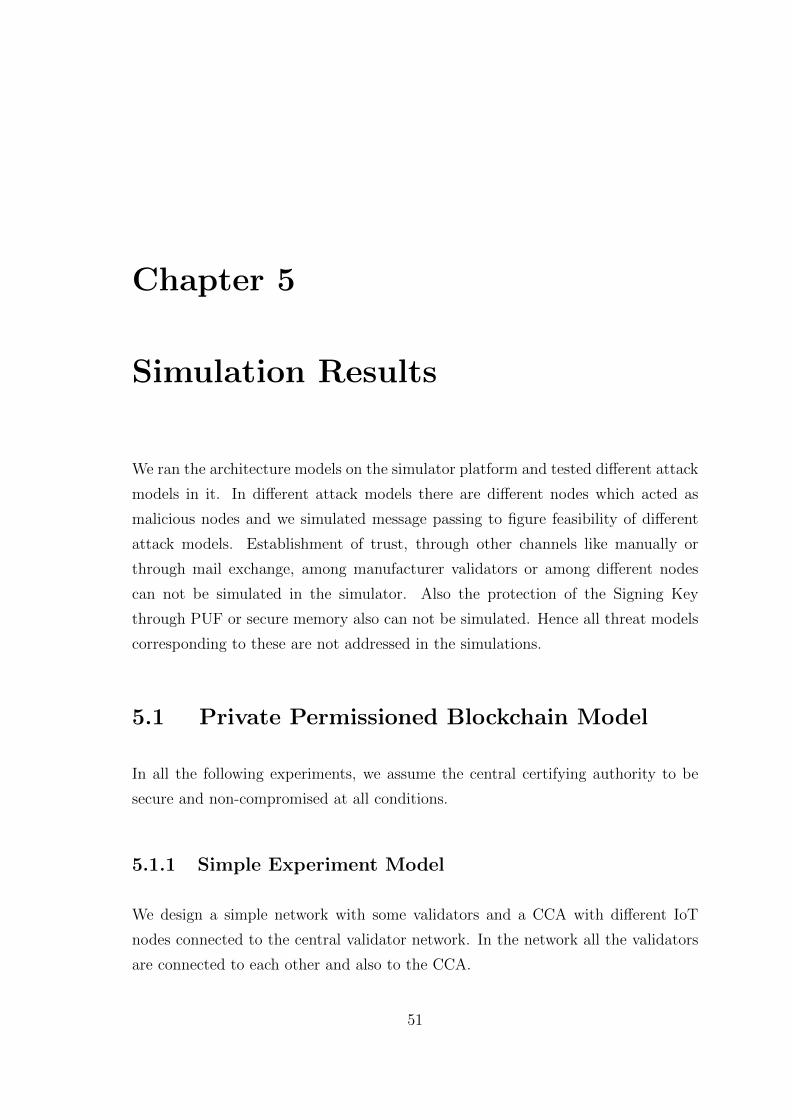
Chapter 5
Simulation Results
We ran the architecture models on the simulator platform and tested different attack
models in it. In different attack models there are different nodes which acted as
malicious nodes and we simulated message passing to figure feasibility of different
attack models. Establishment of trust, through other channels like manually or
through mail exchange, among manufacturer validators or among different nodes
can not be simulated in the simulator. Also the protection of the Signing Key
through PUF or secure memory also can not be simulated. Hence all threat models
corresponding to these are not addressed in the simulations.
5.1 Private Permissioned Blockchain Model
In all the following experiments, we assume the central certifying authority to be
secure and non-compromised at all conditions.
5.1.1 Simple Experiment Model
We design a simple network with some validators and a CCA with different IoT
nodes connected to the central validator network. In the network all the validators
are connected to each other and also to the CCA.
51
Chapter 5. Simulation Results 52
Figure 5.1: Simple Experiment Network
Figure 5.1 shows the topology of the simple experimental network. The result of
running the simulation is given below.
5.1.1.1 Result
Validator 1 is CCA
Validator 2 is of Manufacturer IBM
Validator 3 is of Manufacturer ERICSSON
Validator 4 is of Manufacturer QUALCOMM
Validator 5 is of Manufacturer SILICON
Validator 6 is of Manufacturer QUALCOMM
Building the topology!
Creating list of all nodes!
Forming the CCA and validator links!
Forming the validators links!
Forming validator and device links!
All links formed!
The nodes connections were created in 0.000144005s.
Creating 15 nodes!
Chapter 5. Simulation Results 53
The nodes were created in 0.000437021s.
Creating the links between the validator nodes!
Creating the links between rest of the nodes!
Created all the links!
The total number of links is 24 (0.0288s).
Installing the internet stack!
Internet stack installed in 0.00601697s.
The IP addresses have been assigned in 0.00878096s.
Validator 3: Adding Node 10 public key
Validator 6: Adding Node 11 public key
Validator 5: Adding Node 13 public key
Validator 2: Adding Node 7 public key
Validator 2: Mining Block
Validator 3: Received Block from Validator 2
Validator 4: Received Block from Validator 2
Validator 5: Received Block from Validator 4
Validator 6: Received Block from Validator 3
Validator 4: Adding Node 15 public key
Node 10: Get public key of Node 7
Validator 3: Key request from Node 10
Node 10: Message from Validator 3
Node 10: Received public key of Node 7
Node 10: Sending message to Node 7
Validator 3: Received message from Node 10
Validator 2: Received message from Validator 3
Node 7: Received message from Validator 2
Node 7: Received message from Node 10
Node 7: Received secret key from Node 10
Node 7: Sending message to Node 10
Validator 2: Received message from Node 7
Validator 3: Received message from Validator 2
Node 10: Received message from Validator 3
Node 10: Received message from Node 7
Validator 2: Adding Node 8 public key
Validator 2: Adding Node 9 public key
Node 13: Get public key of Node 14
Validator 5: Key request from Node 14
Validator 5: No key for Node 14
Node 13: Message from Validator 5
Node 13: No public key of Node 14
Validator 6: Adding Node 12 public key
Validator 5: Adding Node 14 public key
Validator 3: Mining Block
Validator 2: Received Block from Validator 3
Validator 6: Received Block from Validator 3
Validator 4: Received Block from Validator 2
Validator 5: Received Block from Validator 6
Node 11: Get public key of Node 15
Validator 6: Key request from Node 11
Node 11: Message from Validator 6
Node 11: Received public key of Node 15
Node 11: Sending message to Node 15
Chapter 5. Simulation Results 54
Validator 6: Received message from Node 11
Validator 5: Received message from Validator 6
Validator 4: Received message from Validator 5
Node 15: Received message from Validator 4
Node 15: Received message from Node 11
Node 15: Received secret key from Node 11
Node 15: Sending message to Node 11
Validator 4: Received message from Node 15
Validator 5: Received message from Validator 4
Validator 6: Received message from Validator 5
Node 11: Received message from Validator 3
Node 11: Received message from Node 15
5.2 Internet 4.0 Model
As it is model in which clusters get merged, so a time based simulation in which
clusters are formed and they are merge into larger clusters, forming bigger networks
would be appropriate. However the link of trust that is established manually be-
tween the manufacturers is not possible to simulate. Hence for the purpose of the
experiments we test by forming small clusters.
5.2.1 Simple Experiment Model
We designed a simple network with two manufacturers, one having 2 PANs in it and
the other having a single PAN in it. The IoT end nodes are within the PAN. The
topology of the network is shown in Figure 5.2.
5.2.1.1 Result
Validator 1 is of Manufacturer QUALCOMM
Validator 2 is of Manufacturer IBM
Building the topology!
Creating list of all nodes!
Forming the validators links!
Forming the gateway links!
All links formed!
The nodes connections were created in 0.000114918s.
Creating 11 nodes!
The nodes were created in 0.000408888s.
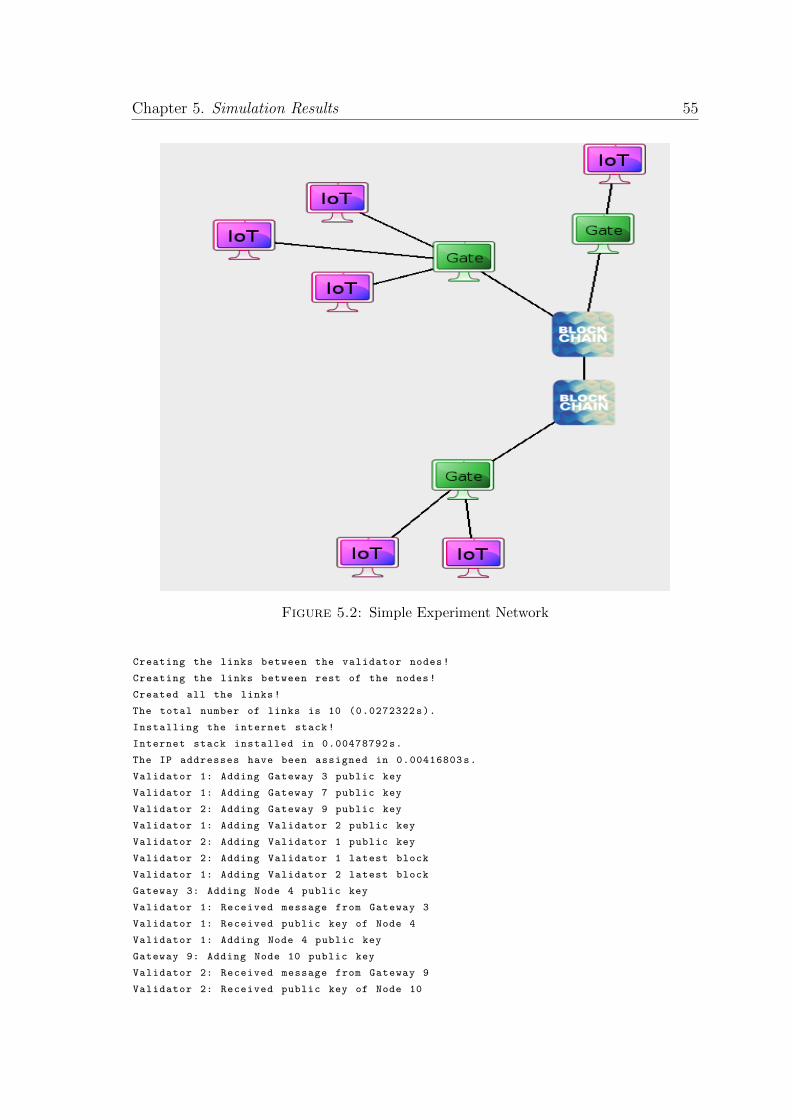
Chapter 5. Simulation Results 55
Figure 5.2: Simple Experiment Network
Creating the links between the validator nodes!
Creating the links between rest of the nodes!
Created all the links!
The total number of links is 10 (0.0272322s).
Installing the internet stack!
Internet stack installed in 0.00478792s.
The IP addresses have been assigned in 0.00416803s.
Validator 1: Adding Gateway 3 public key
Validator 1: Adding Gateway 7 public key
Validator 2: Adding Gateway 9 public key
Validator 1: Adding Validator 2 public key
Validator 2: Adding Validator 1 public key
Validator 2: Adding Validator 1 latest block
Validator 1: Adding Validator 2 latest block
Gateway 3: Adding Node 4 public key
Validator 1: Received message from Gateway 3
Validator 1: Received public key of Node 4
Validator 1: Adding Node 4 public key
Gateway 9: Adding Node 10 public key
Validator 2: Received message from Gateway 9
Validator 2: Received public key of Node 10
Chapter 5. Simulation Results 56
Validator 2: Adding Node 10 public key
Gateway 9: Adding Node 11 public key
Validator 2: Received message from Gateway 11
Validator 2: Received public key of Node 11
Validator 2: Adding Node 11 public key
Gateway 7: Adding Node 8 public key
Validator 1: Received message from Gateway 7
Validator 1: Received public key of Node 8
Validator 1: Adding Node 8 public key
Validator 2: Mining Block
Validator 1: Received Block from Validator 2
Gateway 3: Adding Node 5 public key
Validator 1: Received message from Gateway 3
Validator 1: Received public key of Node 5
Validator 1: Adding Node 5 public key
Gateway 3: Adding Node 6 public key
Validator 1: Received message from Gateway 3
Validator 1: Received public key of Node 6
Validator 1: Adding Node 6 public key
Validator 1: Mining Block
Validator 2: Received Block from Validator 1
Node 4: Get public key of Node 6
Gateway 3: Key request from Node 4
Node 4: Message from Validator 3
Node 4: Received public key of Node 6
Node 4: Sending message to Node 6
Gateway 3: Received message from Node 4
Node 6: Received message from Gateway 3
Node 6: Received message from Node 4
Node 6: Received secret key from Node 4
Node 6: Sending message to Node 4
Gateway 3: Received message from Node 6
Node 4: Received message from Gateway 3
Node 4: Received message from Node 6
Node 10: Get public key of Node 8
Gateway 9: Key request from Node 10
Gateway 9: Key not in store
Validator 2: Key request from Gateway 9
Gateway 9: Received message from Validator 2
Node 10: Message from Gateway 9
Node 10: Received public key of Node 8
Node 10: Sending message to Node 8
Gateway 9: Received message from Node 10
Validator 2: Received message from Gateway 9
Validator 1: Received message from Validator 2
Gateway 7: Received message from Validator 1
Node 8: Received message from Gateway 7
Node 8: Received message from Node 10
Node 8: Received secret key from Node 10
Node 8: Sending message to Node 10
Gateway 7: Received message from Node 8
Validator 1: Received message from Gateway 7
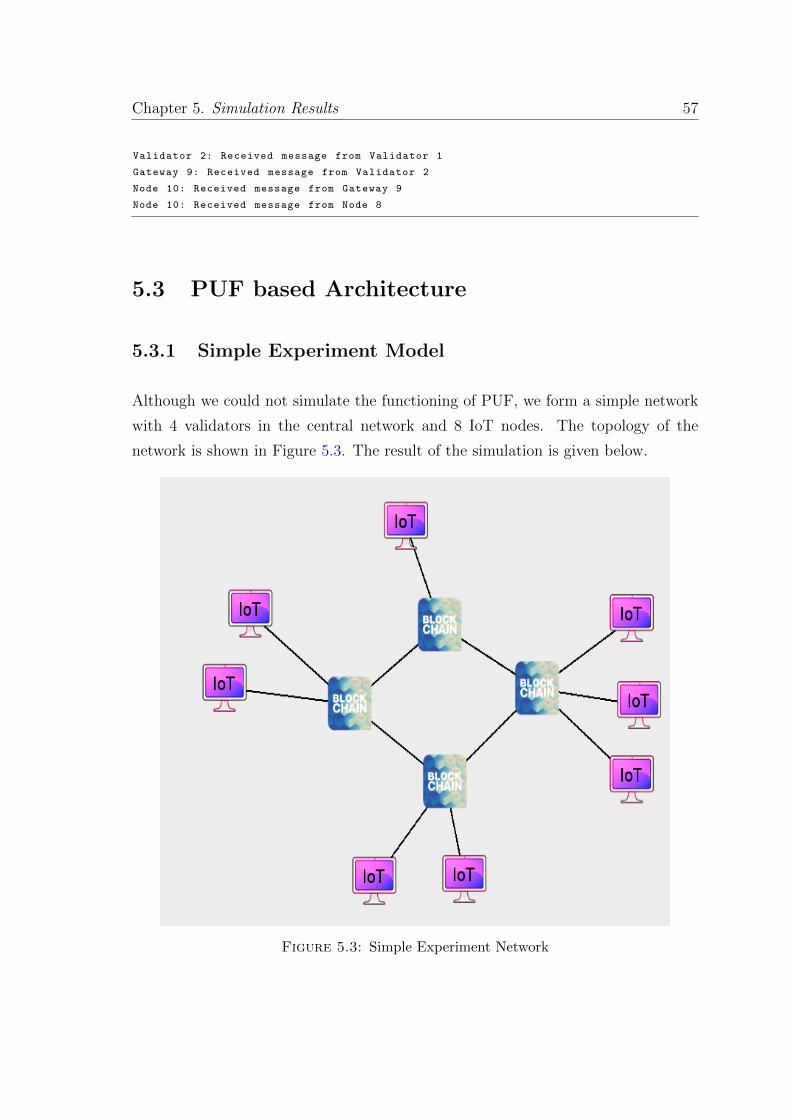
Chapter 5. Simulation Results 57
Validator 2: Received message from Validator 1
Gateway 9: Received message from Validator 2
Node 10: Received message from Gateway 9
Node 10: Received message from Node 8
5.3 PUF based Architecture
5.3.1 Simple Experiment Model
Although we could not simulate the functioning of PUF, we form a simple network
with 4 validators in the central network and 8 IoT nodes. The topology of the
network is shown in Figure 5.3. The result of the simulation is given below.
Figure 5.3: Simple Experiment Network
Chapter 5. Simulation Results 58
5.3.1.1 Result
Building the topology!
Creating list of all nodes!
Forming the validators links!
Forming validator and device links!
All links formed!
The nodes connections were created in 0.000139952s.
Creating 12 nodes!
The nodes were created in 0.000445843s.
Creating the links between the validator nodes!
Creating the links between rest of the nodes!
Created all the links!
The total number of links is 12 (0.0277789s).
Installing the internet stack!
Internet stack installed in 0.00515389s.
The IP addresses have been assigned in 0.00466204s.
Validator 3: Adding signing key with of Node with Id 100
Validator 2: Adding signing key with of Node with Id 101
Validator 1: Adding signing key with of Node with Id 102
Validator 1: Adding signing key with of Node with Id 103
Validator 4: Adding signing key with of Node with Id 104
Validator 3: Adding signing key with of Node with Id 105
Validator 4: Adding signing key with of Node with Id 106
Validator 7: Adding signing key with of Node with Id 107
Validator 1: Adding Node 103 public key
Validator 1: Adding Node 102 public key
Validator 3: Adding Node 100 public key
Validator 2: Adding Node 101 public key
Validator 3: Adding Node 105 public key
Validator 4: Adding Node 104 public key
Validator 4: Adding Node 106 public key
Validator 4: Adding Node 107 public key
Validator 1: Mining Block
Validator 2: Received Block from Validator 1
Validator 3: Received Block from Validator 1
Validator 4: Received Block from Validator 2
Validator 4: Received Block from Validator 3
Node 100: Get public key of Node 107
Validator 3: Key request from Node 100
Node 100: Message from Validator 3
Node 100: Received public key of Node 107
Node 100: Sending message to Node 107
Validator 3: Received message from Node 100
Validator 4: Received message from Validator 3
Node 107: Received message from Validator 4
Node 107: Received message from Node 100
Node 107: Received secret key from Node 100
Node 107: Sending message to Node 100
Validator 4: Received message from Node 107
Validator 3: Received message from Validator 4
Node 100: Received message from Validator 3
Chapter 5. Simulation Results 59
Node 100: Received message from Node 107
Node 102: Get public key of Node 101
Validator 1: Key request from Node 102
Node 102: Message from Validator 1
Node 102: Received public key of Node 101
Node 102: Sending message to Node 101
Validator 1: Received message from Node 102
Validator 2: Received message from Validator 1
Node 101: Received message from Validator 2
Node 101: Received message from Node 102
Node 101: Received secret key from Node 102
Node 101: Sending message to Node 102
Validator 2: Received message from Node 101
Validator 1: Received message from Validator 2
Node 102: Received message from Validator 1
Node 102: Received message from Node 101
5.3.2 ID Exhaustion
While simulating the network we came across a new possible threat model. The id
of the devices are maintained using a integer container in C++ with a incrementing
counter. As integer is a 32 bit container, so there can be maximum of 232 maximum
ids. Hence a malicious device can register as multiple ids and exhaust all ids so
that no other new device may register. This attack depends entirely on how the
management of id is done in the code and having a 256 bit id would make this
attack unfeasible in real life.

Chapter 6
Conclusion
In this thesis we presented 3 different architectures for using key-based message
communication among IoT devices. We also designed a scalable network simulator
to test IoT network simulations in NS3. Case studies for the architectures are as
follows:
6.1 Attack Case Studies
6.1.1 Mirai
The foundation of the Mirai attack was to expand its botnet by brute-forcing into
as many devices as possible and gain control over them. The nature of the brute-
forcing was to use default username password combinations of the devices. If all
the devices use key-based architecture for all the communications then although the
attacker may initiate a communication using the device’s public key but it would
not gain control over the device as the device will reject the communication if the
communicating device is not in its allowed list of devices. Hence the Mirai malware
would not spread and it would have failed. Hajime which is a variant of Mirai would
also fail as its spreading mechanism is the same as that of Mirai.
61
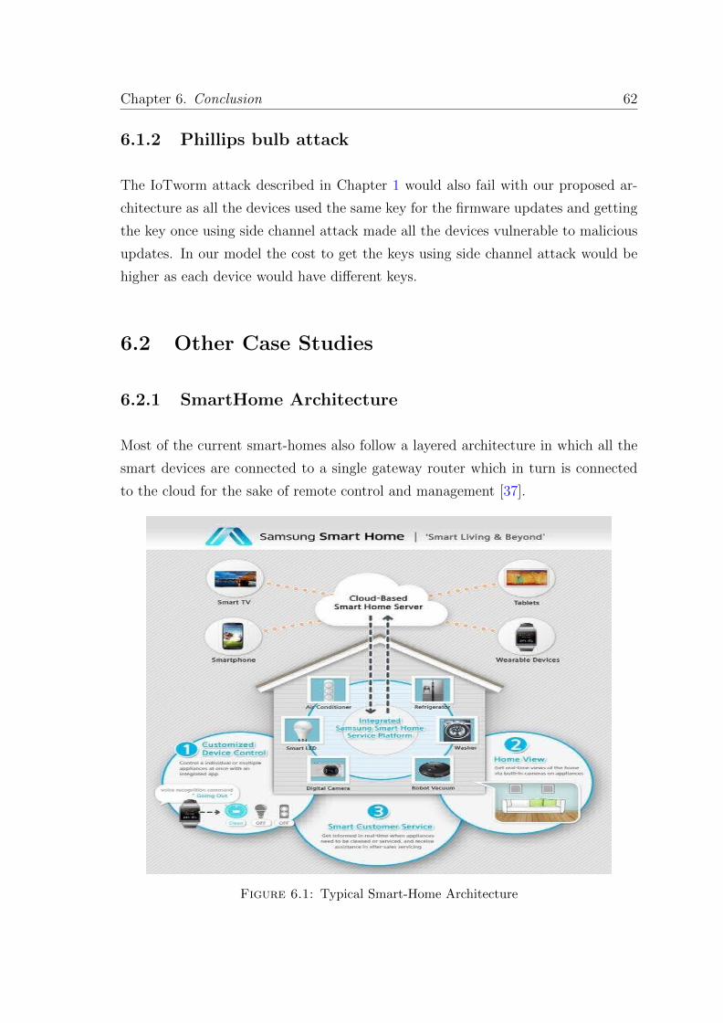
Chapter 6. Conclusion 62
6.1.2 Phillips bulb attack
The IoTworm attack described in Chapter 1 would also fail with our proposed ar-
chitecture as all the devices used the same key for the firmware updates and getting
the key once using side channel attack made all the devices vulnerable to malicious
updates. In our model the cost to get the keys using side channel attack would be
higher as each device would have different keys.
6.2 Other Case Studies
6.2.1 SmartHome Architecture
Most of the current smart-homes also follow a layered architecture in which all the
smart devices are connected to a single gateway router which in turn is connected
to the cloud for the sake of remote control and management [37].
Figure 6.1: Typical Smart-Home Architecture
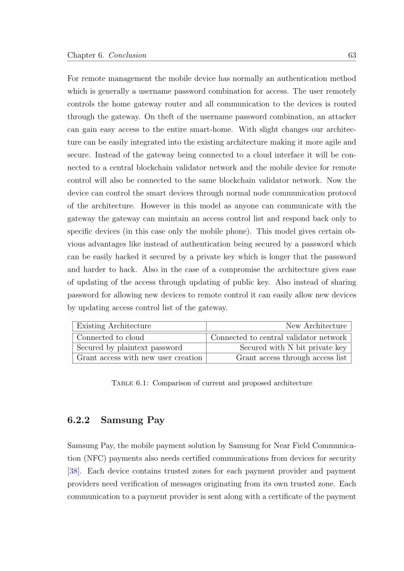
Chapter 6. Conclusion 63
For remote management the mobile device has normally an authentication method
which is generally a username password combination for access. The user remotely
controls the home gateway router and all communication to the devices is routed
through the gateway. On theft of the username password combination, an attacker
can gain easy access to the entire smart-home. With slight changes our architec-
ture can be easily integrated into the existing architecture making it more agile and
secure. Instead of the gateway being connected to a cloud interface it will be con-
nected to a central blockchain validator network and the mobile device for remote
control will also be connected to the same blockchain validator network. Now the
device can control the smart devices through normal node communication protocol
of the architecture. However in this model as anyone can communicate with the
gateway the gateway can maintain an access control list and respond back only to
specific devices (in this case only the mobile phone). This model gives certain ob-
vious advantages like instead of authentication being secured by a password which
can be easily hacked it secured by a private key which is longer that the password
and harder to hack. Also in the case of a compromise the architecture gives ease
of updating of the access through updating of public key. Also instead of sharing
password for allowing new devices to remote control it can easily allow new devices
by updating access control list of the gateway.
Existing Architecture New Architecture
Connected to cloud Connected to central validator networkSecured by plaintext password Secured with N bit private keyGrant access with new user creation Grant access through access list
Table 6.1: Comparison of current and proposed architecture
6.2.2 Samsung Pay
Samsung Pay, the mobile payment solution by Samsung for Near Field Communica-
tion (NFC) payments also needs certified communications from devices for security
[38]. Each device contains trusted zones for each payment provider and payment
providers need verification of messages originating from its own trusted zone. Each
communication to a payment provider is sent along with a certificate of the payment
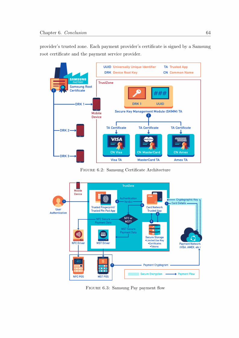
Chapter 6. Conclusion 64
provider’s trusted zone. Each payment provider’s certificate is signed by a Samsung
root certificate and the payment service provider.
Figure 6.2: Samsung Certificate Architecture
Figure 6.3: Samsung Pay payment flow
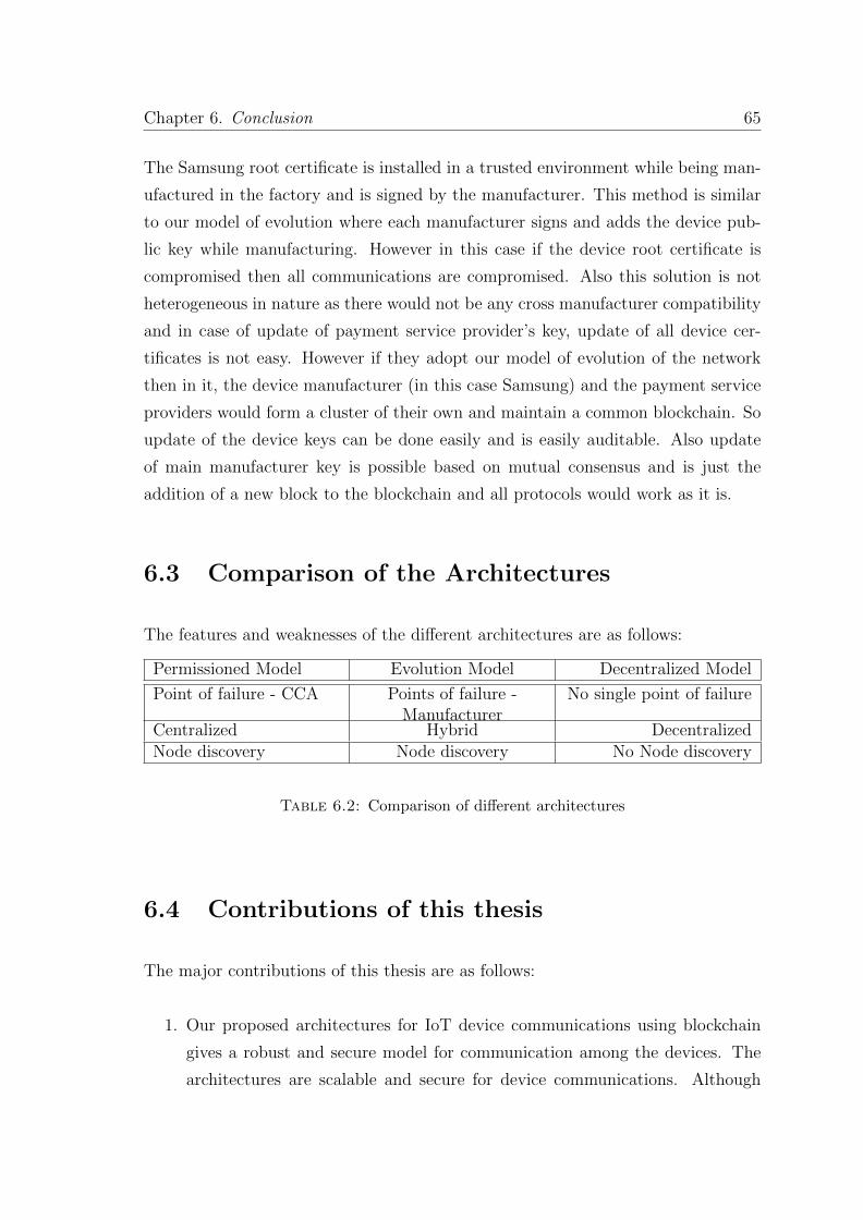
Chapter 6. Conclusion 65
The Samsung root certificate is installed in a trusted environment while being man-
ufactured in the factory and is signed by the manufacturer. This method is similar
to our model of evolution where each manufacturer signs and adds the device pub-
lic key while manufacturing. However in this case if the device root certificate is
compromised then all communications are compromised. Also this solution is not
heterogeneous in nature as there would not be any cross manufacturer compatibility
and in case of update of payment service provider’s key, update of all device cer-
tificates is not easy. However if they adopt our model of evolution of the network
then in it, the device manufacturer (in this case Samsung) and the payment service
providers would form a cluster of their own and maintain a common blockchain. So
update of the device keys can be done easily and is easily auditable. Also update
of main manufacturer key is possible based on mutual consensus and is just the
addition of a new block to the blockchain and all protocols would work as it is.
6.3 Comparison of the Architectures
The features and weaknesses of the different architectures are as follows:
Permissioned Model Evolution Model Decentralized Model
Point of failure - CCA Points of failure -Manufacturer
No single point of failure
Centralized Hybrid DecentralizedNode discovery Node discovery No Node discovery
Table 6.2: Comparison of different architectures
6.4 Contributions of this thesis
The major contributions of this thesis are as follows:
1. Our proposed architectures for IoT device communications using blockchain
gives a robust and secure model for communication among the devices. The
architectures are scalable and secure for device communications. Although
Chapter 6. Conclusion 66
there is a overhead for encryption & decryption in key-based communication
but this overhead would be minimal as normal username password based au-
thentication would also require a secure channel or else it would be vulnerable
to sniffing attack. Also this model gives flexibility as any device willing to
establish communication with some device can do so.
2. Our work also gives a IoT simulator in NS3. Now IoT network models with
IoT protocols can be easily designed and tested in NS3.

Chapter 7
Future Work
The possible improvements in the simulator and the architecture are as follows:
7.1 Architecture
• Quantum blockchains The authors in [39] describe a way for securing blockchain
using quantum computing. They define a consensus protocol for the blockchain
which is secure against even quantum computing and doesn’t need the com-
putationally intensive proof of work for the consensus. Their work uses the
quantum key distribution to guarantee authentication in the protocol and as
quantum key distribution is based on the laws of quantum physics so the mes-
sage can not be tampered without destroying it. As quantum computing is
the future so a protocol using quantum secured blockchain would be required.
• Formal method verification In order to properly verify the different threat
models and workings of a protocol, proper formal method verification of a
protocol needs to be done. Formal method verification of all 3 protocols need
to be done in order to find new vulnerabilities and test existing threat models
for the protocols.
• More Robust Decentralized Model Currently on compromise of the Sign-
ing Key would make the device useless. A more robust model would even allow
the update of the Signing Key on compromise.
68
Chapter 7. Future Work 69
7.2 Simulator
• Nodes Currently the different IoT nodes, validator and gateway nodes are
implemented as applications in NS3. However they need to be implemented
as node classes which can be extended easily.
• IoT Sensors After IoT nodes are implemented as node classes, different ap-
plication classes can be implemented which simulate functionalities of different
IoT sensors to send sensor data.
• Batch Deploy Currently the simulator allows the nodes to be deployed indi-
vidually. However batch deploy of multiple IoT nodes would be a good feature.
• Communication Protocols Functionality for different nodes communicate
over other protocols like LTE, Zigbee would be a nice feature.

Appendix A
Public Key Cryptography
Before the advent of public key cryptography there was only symmetric key cryp-
tography where both parties had a common key and all communications used to
happen by encrypting using the common key. However the common key needed
to be transferred using some physical channel or some trusted courier. Then came
the the public key cryptography which eliminated the need for this secure physical
channel.
Diffie-Hellman Key Exchange: Diffie-Hellman Key Exchange was the first of the
protocols for public-key cryptography [5]. It allowed establishing a secret key among
two parties even when both are initially communicating on a open, unencrypted
channel. The protocol uses mathematical functions in order to establish the secret
key. The working of the protocol is explained below.
General Explanation
Communicating parties A and B need to choose an arbitrary color which may not be
secret but needs to be different every time. Suppose the color is yellow. Now both
A and B selects some secret colors which they keep to themselves. Let the secret
colors be red and aqua. Now both parties mix their own chosen secret color with
the decided common color. So in this case A mixes red and yellow and forms orange
and B mixes aqua and yellow and forms blue. Now A and B exchange their mixed
colors with each other. Now each partner mixes his own chosen secret color with
the mixed color he received from his partner and forms the common secret among
71
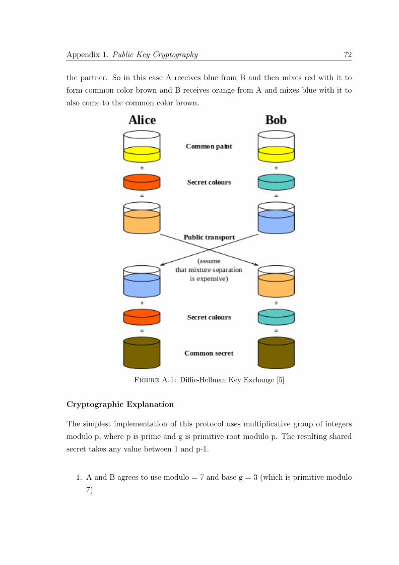
Appendix 1. Public Key Cryptography 72
the partner. So in this case A receives blue from B and then mixes red with it to
form common color brown and B receives orange from A and mixes blue with it to
also come to the common color brown.
Figure A.1: Diffie-Hellman Key Exchange [5]
Cryptographic Explanation
The simplest implementation of this protocol uses multiplicative group of integers
modulo p, where p is prime and g is primitive root modulo p. The resulting shared
secret takes any value between 1 and p-1.
1. A and B agrees to use modulo = 7 and base g = 3 (which is primitive modulo
7)
Appendix 1. Public Key Cryptography 73
2. A chooses a secret integer say 11 and then sends B 311 mod 7 which is 5.
3. B chooses a secret integer say 51 and then sends A 351 mod 7 which is 6.
4. A now computes 611 mod 7 and get secret as 6.
5. B now computes 551 mod 7 and get secret as 6.
6. Now both A and B share the secret key of 6 among them.
RSA Algorithm: The RSA algorithm was discovered later by three people Rivest,
Shamir and Adleman on whose name the algorithm was named. This protocol also
uses the mathematical property of primes that it is hard to find the prime factors of
a number which is the product of two very large primes. In this protocol there are
2 distinct set of keys used for encryption and decryption. There are 2 keys called
public key and private key. The public key as the name suggests is public and known
to everyone and the private key is only known to the user. Now anyone can send a
message to the user by encrypting using the public key of the user and only the user
can decrypt the message as the message can only be decrypted using the private
key which is with the user. Now signing of a message works in the reverse order in
which the user signs the message with his private key (signing algorithm is same as
the encryption algorithm) and anyone can verify the signature using the public key
(verification algorithm is same as decryption algorithm).
Let there be 3 positive integers e,d and n. Let the message be m. Now the public
key consists of e and n. So a simple encryption algorithm would be c = me mod n
. Now e and d are chosen in a way such that (me)d = m mod n. Now decrypting
the encrypted message c would be cd mod n = (me)d mod n = m.
Elliptic Curve Cryptography Elliptic Curve Cryptography came after RSA and
it is based on the algebraic structure of elliptic curves over finite fields. ECC al-
gorithms use much smaller key sizes as compared to RSA algorithms and also re-
quires much less computational power to provide the same security. The mathemat-
ical problem behind this protocol is the ”elliptic curve discrete logarithm problem”
(ECDLP) which states that it is infeasible to find the discrete logarithm of a ran-
dom elliptic curve element with respect to a publicly known base point. Multiple
cryptographic schemes have been developed based on this elliptic curve problem.

Appendix B
Simulator Class Codes and
Explanation
The simulator contains 2 parts: the IoT-generator and the NS3 classes implementing
the IoT and blockchain logic.
B.1 IoT-Generator
B.1.1 Generator Header File
#ifndef GENERATOR_H
#define GENERATOR_H
#include "node.h"
#include "network -hardware.h"
#include "application.h"
#include <iostream >
#include <fstream >
#include <string >
#include <vector >
/**
* \ingroup generator
* \brief The main class of the Generator.
*
* The Generator class is the main class of the kern folder.
75
Appendix B. Simulator Class Codes and Explanation 76
* It is used for call all the classes you can found here.
*
* This class works around three vector which contain Nodes , Links and Applications.
*
* Usage example:
* - create an Generator object ,
* Generator *gen = new Generator(std:: string (" Simulation Name "));
* - add nodes ,
* gen ->AddNode(std:: string ("Pc "));// or router , wifi station , ...
* - add links ,
* gen ->AddNetworkHardware(std:: string ("Hub "));// or ap, bridge , ....
* - connect nodes to link ,
* gen ->(link)->Install(Node name);
* - add applications ,
* gen ->AddApplication(std:: string ("Ping"), senderNodeName , receiverNodeName , startTime , endTime );
*
* You can see all examples of all implementation into kern/examples/ folder.
*/
class Generator
{
public:
/**
* \brief Constructor.
* \param simulationName simulation name
*/
Generator(const std:: string &simulationName );
/**
* \brief Destructor.
*/
~Generator ();
/**
* \brief Add a config line.
* \param config new config to add to config list
*/
void AddConfig(const std:: string &config );
/**
* \brief Add an node.
*
* This used to add an node. It add the node to the
* vector listNode and increment the number of node.
*
* \param type node type. (pc , hub , switch ,...)
*/
void AddNode(const std:: string &type);
/**
* \brief Add an node group.
* \param type node type
* \param number number which will be added
Appendix B. Simulator Class Codes and Explanation 77
*/
void AddNode(const std:: string &type , const size_t number );
/**
* \brief Remove an node element.
* \param name node name to remove
*/
void RemoveNode(const std:: string &name);
/**
* \brief Remove an node element.
* \param index node index to be removed
*/
void RemoveNode(const size_t index);
/**
* \brief Get node at specified index.
* \param index index
* \return node pointer
*/
Node* GetNode(const size_t index );
/**
* \brief Get number of nodes.
* \return number of nodes.
*/
size_t GetNNodes () const;
/**
* \brief Add an appplication.
*
* This procedure is used to add an procedure. It add the application to the
* vector listApplication and increment the number of application.
*
* \param type type of the application. (ping , tcp -large -transfert , udp -echo ...)
* \param senderNode sender node
* \param receiverNode receiver node
* \param startTime start time
* \param endTime end time
* \param port port
*/
void AddApplication(const std:: string &type , const std:: string &senderNode , const std:: string &receiverNode , const size_t &startTime , const size_t &endTime , const size_t &port);
/**
* \brief Add an application.
*
* This procedure is used to add an procedure. It add the application to the
* vector listApplication and increment the number of application.
*
* \param type the type of the application. (ping , tcp -large -transfert , udp -echo ...)
* \param senderNode sender node
* \param receiverNode receiver node
Appendix B. Simulator Class Codes and Explanation 78
* \param startTime start time
* \param endTime end time
*/
void AddApplication(const std:: string &type , const std:: string &senderNode , const std:: string &receiverNode , const size_t &startTime , const size_t &endTime );
/**
* \brief Remove an application element.
* \param name application name to remove
*/
void RemoveApplication(const std:: string &name);
/**
* \brief Get application element at specified index.
* \param index index
* \return application pointer
*/
Application* GetApplication(const size_t index);
/**
* \brief Get number of applications.
* \return number of applications
*/
size_t GetNApplications () const;
/**
* \brief Add an link.
*
* This procedure is used to add an link. It add the link to the
* vector listLink and increment the number of link.
*
* \param type type of the link. (point -to-point , csma ,...)
*/
void AddNetworkHardware(const std:: string &type);
/**
* \brief Add link and his linkNode.
*
* Example , an Ap, must have an ap node to be generated.
*
* \param type link type
* \param linkNode node name
*/
void AddNetworkHardware(const std:: string &type , const std:: string &linkNode );
/**
* \brief Add link with her linkNode and ifaceName.
*
* \param type link type
* \param linkNode node name
* \param ifaceName iface name
*/
void AddNetworkHardware(const std:: string &type , const std:: string &linkNode , const std:: string &ifaceName );
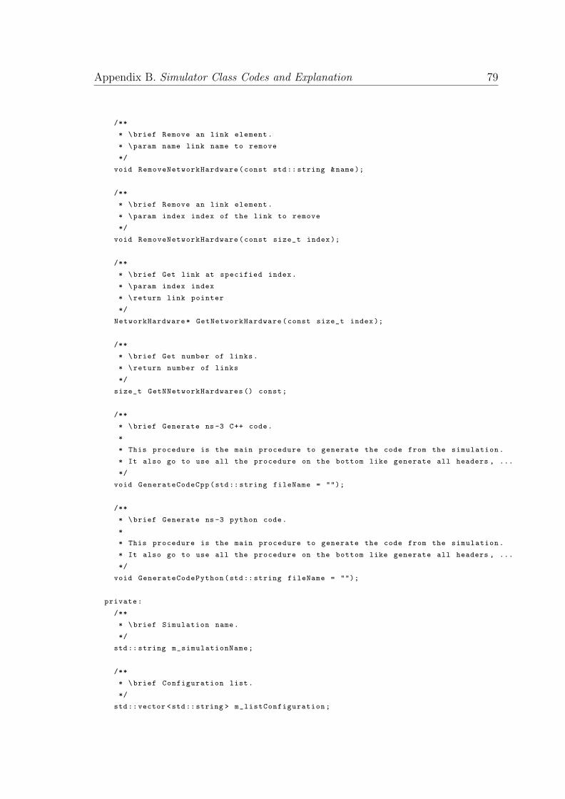
Appendix B. Simulator Class Codes and Explanation 79
/**
* \brief Remove an link element.
* \param name link name to remove
*/
void RemoveNetworkHardware(const std:: string &name);
/**
* \brief Remove an link element.
* \param index index of the link to remove
*/
void RemoveNetworkHardware(const size_t index);
/**
* \brief Get link at specified index.
* \param index index
* \return link pointer
*/
NetworkHardware* GetNetworkHardware(const size_t index );
/**
* \brief Get number of links.
* \return number of links
*/
size_t GetNNetworkHardwares () const;
/**
* \brief Generate ns -3 C++ code.
*
* This procedure is the main procedure to generate the code from the simulation.
* It also go to use all the procedure on the bottom like generate all headers , ...
*/
void GenerateCodeCpp(std:: string fileName = "");
/**
* \brief Generate ns -3 python code.
*
* This procedure is the main procedure to generate the code from the simulation.
* It also go to use all the procedure on the bottom like generate all headers , ...
*/
void GenerateCodePython(std:: string fileName = "");
private:
/**
* \brief Simulation name.
*/
std:: string m_simulationName;
/**
* \brief Configuration list.
*/
std::vector <std::string > m_listConfiguration;
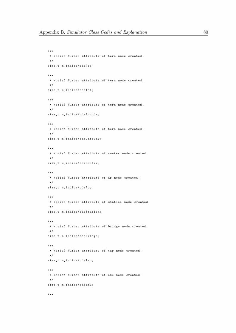
Appendix B. Simulator Class Codes and Explanation 80
/**
* \brief Number attribute of term node created.
*/
size_t m_indiceNodePc;
/**
* \brief Number attribute of term node created.
*/
size_t m_indiceNodeIot;
/**
* \brief Number attribute of term node created.
*/
size_t m_indiceNodeBcnode;
/**
* \brief Number attribute of term node created.
*/
size_t m_indiceNodeGateway;
/**
* \brief Number attribute of router node created.
*/
size_t m_indiceNodeRouter;
/**
* \brief Number attribute of ap node created.
*/
size_t m_indiceNodeAp;
/**
* \brief Number attribute of station node created.
*/
size_t m_indiceNodeStation;
/**
* \brief Number attribute of bridge node created.
*/
size_t m_indiceNodeBridge;
/**
* \brief Number attribute of tap node created.
*/
size_t m_indiceNodeTap;
/**
* \brief Number attribute of emu node created.
*/
size_t m_indiceNodeEmu;
/**
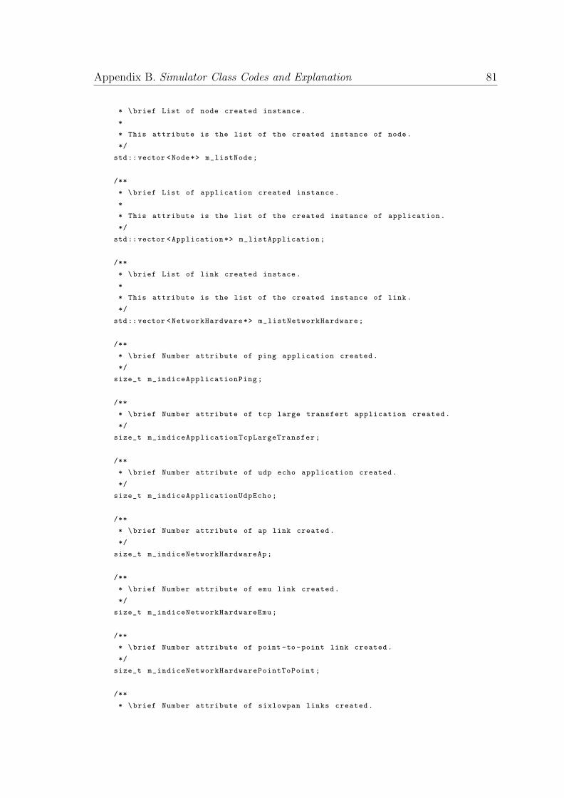
Appendix B. Simulator Class Codes and Explanation 81
* \brief List of node created instance.
*
* This attribute is the list of the created instance of node.
*/
std::vector <Node*> m_listNode;
/**
* \brief List of application created instance.
*
* This attribute is the list of the created instance of application.
*/
std::vector <Application*> m_listApplication;
/**
* \brief List of link created instace.
*
* This attribute is the list of the created instance of link.
*/
std::vector <NetworkHardware*> m_listNetworkHardware;
/**
* \brief Number attribute of ping application created.
*/
size_t m_indiceApplicationPing;
/**
* \brief Number attribute of tcp large transfert application created.
*/
size_t m_indiceApplicationTcpLargeTransfer;
/**
* \brief Number attribute of udp echo application created.
*/
size_t m_indiceApplicationUdpEcho;
/**
* \brief Number attribute of ap link created.
*/
size_t m_indiceNetworkHardwareAp;
/**
* \brief Number attribute of emu link created.
*/
size_t m_indiceNetworkHardwareEmu;
/**
* \brief Number attribute of point -to-point link created.
*/
size_t m_indiceNetworkHardwarePointToPoint;
/**
* \brief Number attribute of sixlowpan links created.
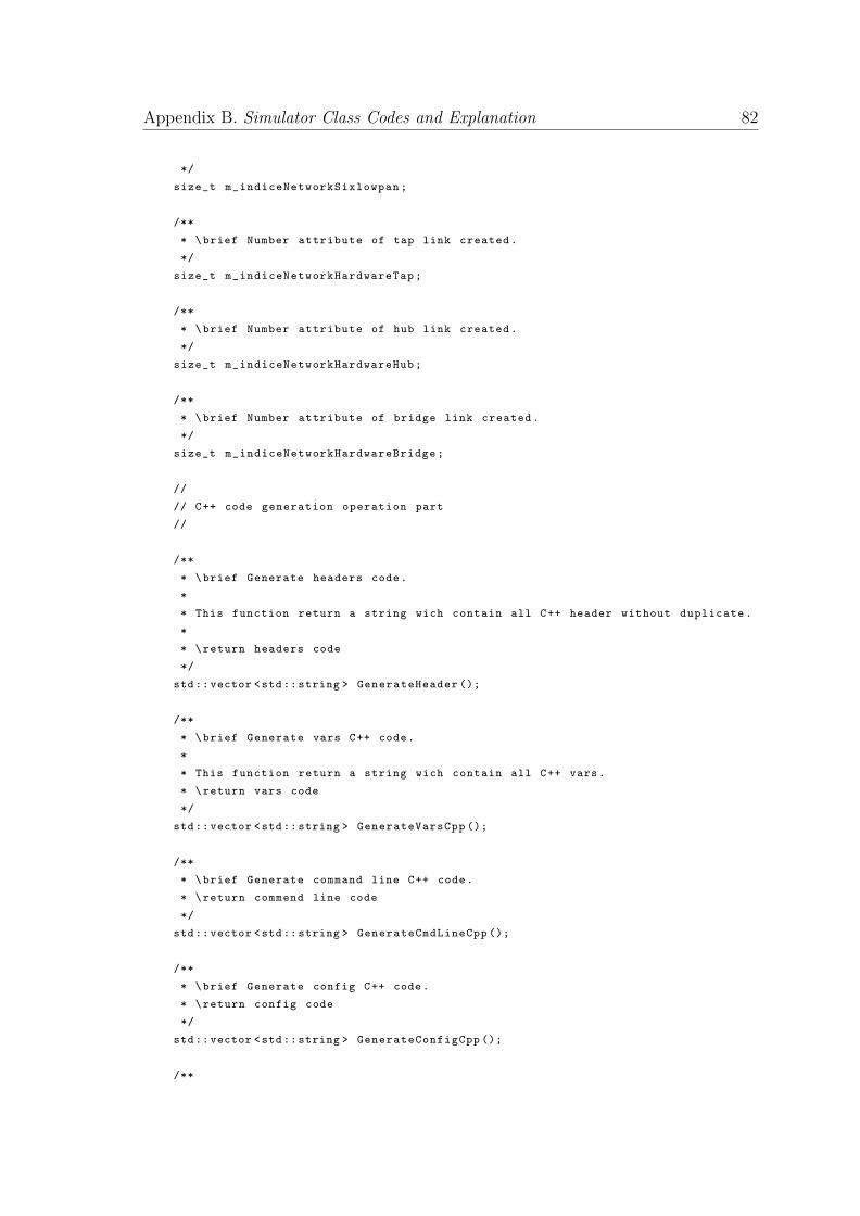
Appendix B. Simulator Class Codes and Explanation 82
*/
size_t m_indiceNetworkSixlowpan;
/**
* \brief Number attribute of tap link created.
*/
size_t m_indiceNetworkHardwareTap;
/**
* \brief Number attribute of hub link created.
*/
size_t m_indiceNetworkHardwareHub;
/**
* \brief Number attribute of bridge link created.
*/
size_t m_indiceNetworkHardwareBridge;
//
// C++ code generation operation part
//
/**
* \brief Generate headers code.
*
* This function return a string wich contain all C++ header without duplicate.
*
* \return headers code
*/
std::vector <std::string > GenerateHeader ();
/**
* \brief Generate vars C++ code.
*
* This function return a string wich contain all C++ vars.
* \return vars code
*/
std::vector <std::string > GenerateVarsCpp ();
/**
* \brief Generate command line C++ code.
* \return commend line code
*/
std::vector <std::string > GenerateCmdLineCpp ();
/**
* \brief Generate config C++ code.
* \return config code
*/
std::vector <std::string > GenerateConfigCpp ();
/**
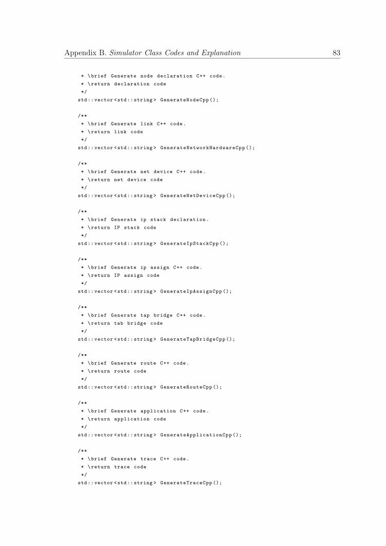
Appendix B. Simulator Class Codes and Explanation 83
* \brief Generate node declaration C++ code.
* \return declaration code
*/
std::vector <std::string > GenerateNodeCpp ();
/**
* \brief Generate link C++ code.
* \return link code
*/
std::vector <std::string > GenerateNetworkHardwareCpp ();
/**
* \brief Generate net device C++ code.
* \return net device code
*/
std::vector <std::string > GenerateNetDeviceCpp ();
/**
* \brief Generate ip stack declaration.
* \return IP stack code
*/
std::vector <std::string > GenerateIpStackCpp ();
/**
* \brief Generate ip assign C++ code.
* \return IP assign code
*/
std::vector <std::string > GenerateIpAssignCpp ();
/**
* \brief Generate tap bridge C++ code.
* \return tab bridge code
*/
std::vector <std::string > GenerateTapBridgeCpp ();
/**
* \brief Generate route C++ code.
* \return route code
*/
std::vector <std::string > GenerateRouteCpp ();
/**
* \brief Generate application C++ code.
* \return application code
*/
std::vector <std::string > GenerateApplicationCpp ();
/**
* \brief Generate trace C++ code.
* \return trace code
*/
std::vector <std::string > GenerateTraceCpp ();
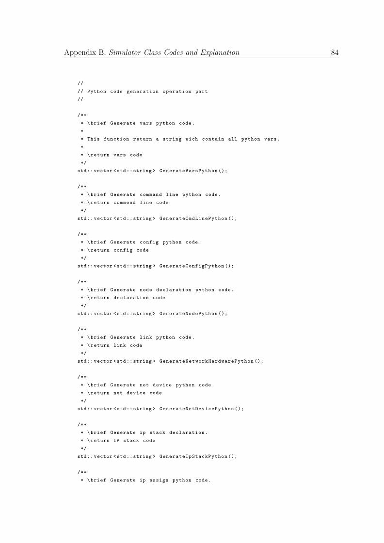
Appendix B. Simulator Class Codes and Explanation 84
//
// Python code generation operation part
//
/**
* \brief Generate vars python code.
*
* This function return a string wich contain all python vars.
*
* \return vars code
*/
std::vector <std::string > GenerateVarsPython ();
/**
* \brief Generate command line python code.
* \return commend line code
*/
std::vector <std::string > GenerateCmdLinePython ();
/**
* \brief Generate config python code.
* \return config code
*/
std::vector <std::string > GenerateConfigPython ();
/**
* \brief Generate node declaration python code.
* \return declaration code
*/
std::vector <std::string > GenerateNodePython ();
/**
* \brief Generate link python code.
* \return link code
*/
std::vector <std::string > GenerateNetworkHardwarePython ();
/**
* \brief Generate net device python code.
* \return net device code
*/
std::vector <std::string > GenerateNetDevicePython ();
/**
* \brief Generate ip stack declaration.
* \return IP stack code
*/
std::vector <std::string > GenerateIpStackPython ();
/**
* \brief Generate ip assign python code.
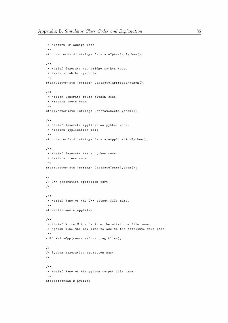
Appendix B. Simulator Class Codes and Explanation 85
* \return IP assign code
*/
std::vector <std::string > GenerateIpAssignPython ();
/**
* \brief Generate tap bridge python code.
* \return tab bridge code
*/
std::vector <std::string > GenerateTapBridgePython ();
/**
* \brief Generate route python code.
* \return route code
*/
std::vector <std::string > GenerateRoutePython ();
/**
* \brief Generate application python code.
* \return application code
*/
std::vector <std::string > GenerateApplicationPython ();
/**
* \brief Generate trace python code.
* \return trace code
*/
std::vector <std::string > GenerateTracePython ();
//
// C++ generation operation part.
//
/**
* \brief Name of the C++ output file name.
*/
std:: ofstream m_cppFile;
/**
* \brief Write C++ code into the attribute file name.
* \param line the new line to add to the attribute file name
*/
void WriteCpp(const std:: string &line);
//
// Python generation operation part.
//
/**
* \brief Name of the python output file name.
*/
std:: ofstream m_pyFile;
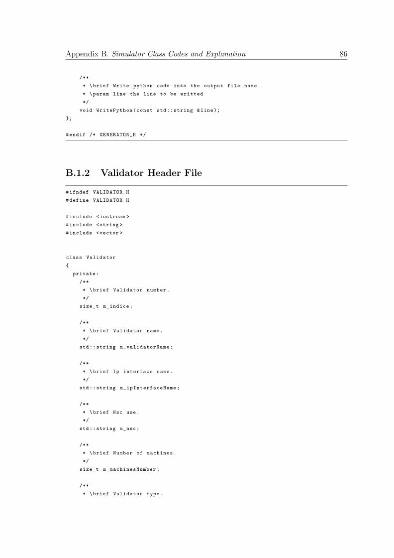
Appendix B. Simulator Class Codes and Explanation 86
/**
* \brief Write python code into the output file name.
* \param line the line to be writted
*/
void WritePython(const std:: string &line);
};
#endif /* GENERATOR_H */
B.1.2 Validator Header File
#ifndef VALIDATOR_H
#define VALIDATOR_H
#include <iostream >
#include <string >
#include <vector >
class Validator
{
private:
/**
* \brief Validator number.
*/
size_t m_indice;
/**
* \brief Validator name.
*/
std:: string m_validatorName;
/**
* \brief Ip interface name.
*/
std:: string m_ipInterfaceName;
/**
* \brief Nsc use.
*/
std:: string m_nsc;
/**
* \brief Number of machines.
*/
size_t m_machinesNumber;
/**
* \brief Validator type.
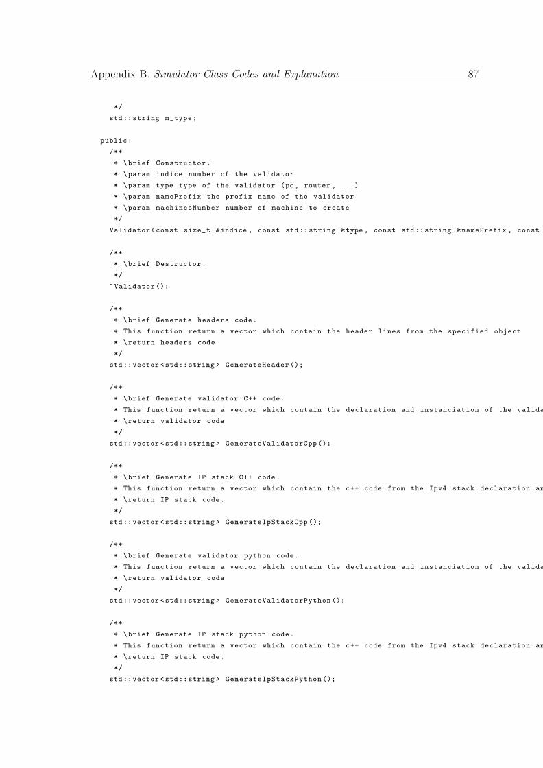
Appendix B. Simulator Class Codes and Explanation 87
*/
std:: string m_type;
public:
/**
* \brief Constructor.
* \param indice number of the validator
* \param type type of the validator (pc , router , ...)
* \param namePrefix the prefix name of the validator
* \param machinesNumber number of machine to create
*/
Validator(const size_t &indice , const std:: string &type , const std:: string &namePrefix , const size_t &machinesNumber );
/**
* \brief Destructor.
*/
~Validator ();
/**
* \brief Generate headers code.
* This function return a vector which contain the header lines from the specified object
* \return headers code
*/
std::vector <std::string > GenerateHeader ();
/**
* \brief Generate validator C++ code.
* This function return a vector which contain the declaration and instanciation of the validator
* \return validator code
*/
std::vector <std::string > GenerateValidatorCpp ();
/**
* \brief Generate IP stack C++ code.
* This function return a vector which contain the c++ code from the Ipv4 stack declaration and instanciation
* \return IP stack code.
*/
std::vector <std::string > GenerateIpStackCpp ();
/**
* \brief Generate validator python code.
* This function return a vector which contain the declaration and instanciation of the validator
* \return validator code
*/
std::vector <std::string > GenerateValidatorPython ();
/**
* \brief Generate IP stack python code.
* This function return a vector which contain the c++ code from the Ipv4 stack declaration and instanciation
* \return IP stack code.
*/
std::vector <std::string > GenerateIpStackPython ();
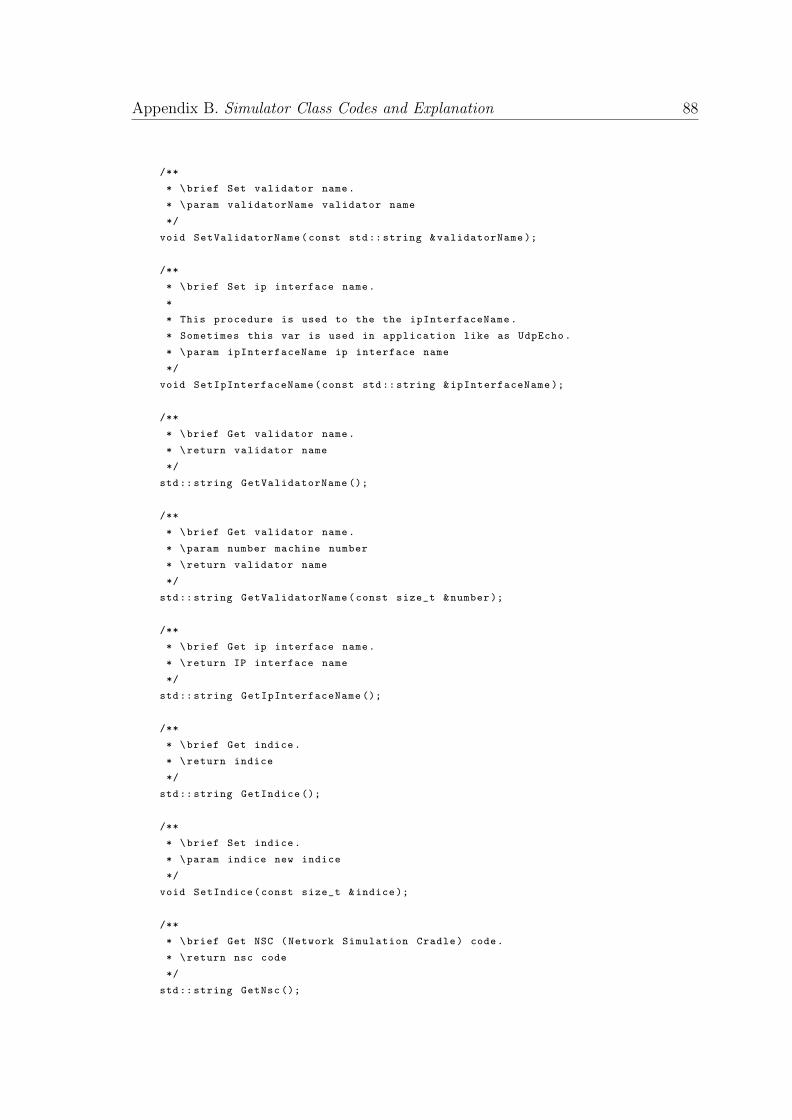
Appendix B. Simulator Class Codes and Explanation 88
/**
* \brief Set validator name.
* \param validatorName validator name
*/
void SetValidatorName(const std:: string &validatorName );
/**
* \brief Set ip interface name.
*
* This procedure is used to the the ipInterfaceName.
* Sometimes this var is used in application like as UdpEcho.
* \param ipInterfaceName ip interface name
*/
void SetIpInterfaceName(const std:: string &ipInterfaceName );
/**
* \brief Get validator name.
* \return validator name
*/
std:: string GetValidatorName ();
/**
* \brief Get validator name.
* \param number machine number
* \return validator name
*/
std:: string GetValidatorName(const size_t &number );
/**
* \brief Get ip interface name.
* \return IP interface name
*/
std:: string GetIpInterfaceName ();
/**
* \brief Get indice.
* \return indice
*/
std:: string GetIndice ();
/**
* \brief Set indice.
* \param indice new indice
*/
void SetIndice(const size_t &indice );
/**
* \brief Get NSC (Network Simulation Cradle) code.
* \return nsc code
*/
std:: string GetNsc ();
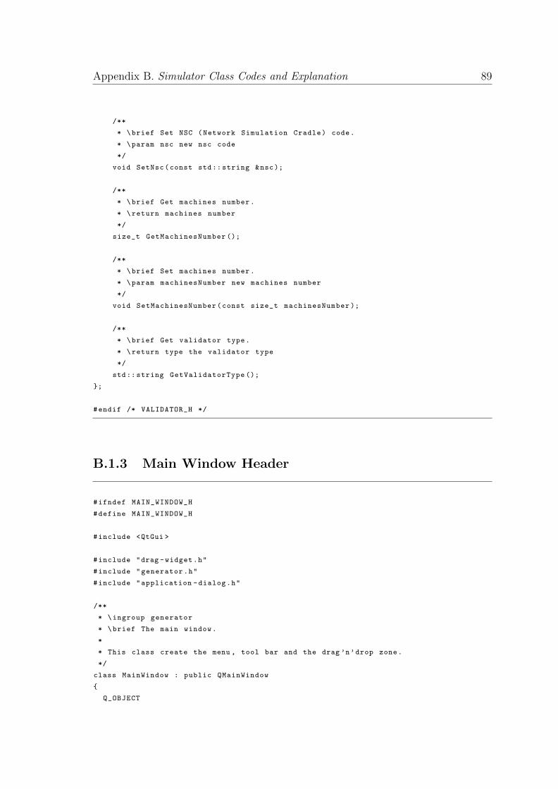
Appendix B. Simulator Class Codes and Explanation 89
/**
* \brief Set NSC (Network Simulation Cradle) code.
* \param nsc new nsc code
*/
void SetNsc(const std:: string &nsc);
/**
* \brief Get machines number.
* \return machines number
*/
size_t GetMachinesNumber ();
/**
* \brief Set machines number.
* \param machinesNumber new machines number
*/
void SetMachinesNumber(const size_t machinesNumber );
/**
* \brief Get validator type.
* \return type the validator type
*/
std:: string GetValidatorType ();
};
#endif /* VALIDATOR_H */
B.1.3 Main Window Header
#ifndef MAIN_WINDOW_H
#define MAIN_WINDOW_H
#include <QtGui >
#include "drag -widget.h"
#include "generator.h"
#include "application -dialog.h"
/**
* \ingroup generator
* \brief The main window.
*
* This class create the menu , tool bar and the drag ’n’drop zone.
*/
class MainWindow : public QMainWindow
{
Q_OBJECT
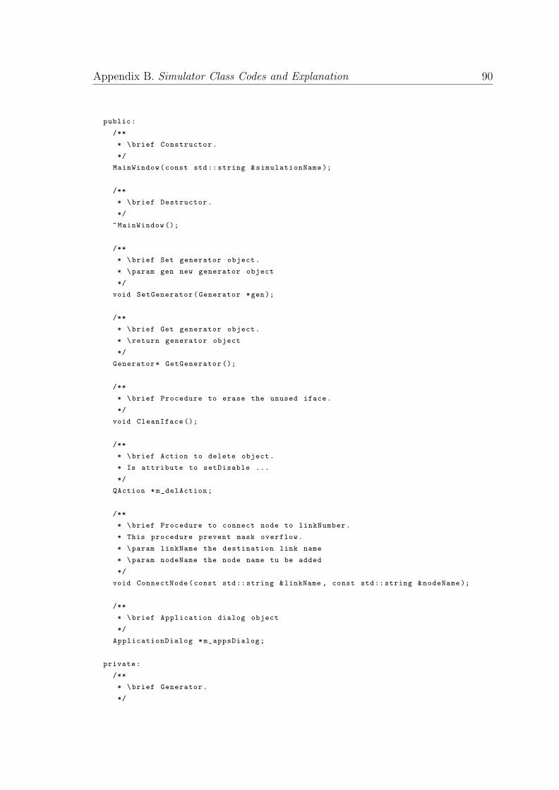
Appendix B. Simulator Class Codes and Explanation 90
public:
/**
* \brief Constructor.
*/
MainWindow(const std:: string &simulationName );
/**
* \brief Destructor.
*/
~MainWindow ();
/**
* \brief Set generator object.
* \param gen new generator object
*/
void SetGenerator(Generator *gen);
/**
* \brief Get generator object.
* \return generator object
*/
Generator* GetGenerator ();
/**
* \brief Procedure to erase the unused iface.
*/
void CleanIface ();
/**
* \brief Action to delete object.
* Is attribute to setDisable ...
*/
QAction *m_delAction;
/**
* \brief Procedure to connect node to linkNumber.
* This procedure prevent mask overflow.
* \param linkName the destination link name
* \param nodeName the node name tu be added
*/
void ConnectNode(const std:: string &linkName , const std:: string &nodeName );
/**
* \brief Application dialog object
*/
ApplicationDialog *m_appsDialog;
private:
/**
* \brief Generator.
*/
Appendix B. Simulator Class Codes and Explanation 91
Generator *m_gen;
/**
* \brief The drag ’n’drop zone.
*/
DragWidget *m_dw;
/**
* \brief interface which are used.
*/
std::vector <std::string > m_listIface;
private slots:
/**
* \brief Create PC.
*/
void CreatePc ();
/**
* \brief Create PC.
*/
void CreateIoT ();
/**
* \brief Create PC.
*/
void CreateBCNode ();
/**
* \brief Create PC.
*/
void CreateGateway ();
/**
* \brief Create group of PCs.
*/
void CreatePcGroup ();
/**
* \brief Create an "Emu" link.
*/
void CreateEmu ();
/**
* \brief Create a tap device.
*/
void CreateTap ();
/**
* \brief Create an access point (AP).
*/
Appendix B. Simulator Class Codes and Explanation 92
void CreateAp ();
/**
* \brief Create a WI -FI station.
*/
void CreateStation ();
/**
* \brief Create a hub (csma link)
*/
void CreateHub ();
/**
* \brief Create a switch (bridge)
*/
void CreateSwitch ();
/**
* \brief Create a router.
*/
void CreateRouter ();
/**
* \brief Create a wired link from equipement to equipement.
*/
void CreateWiredLink ();
/**
* \brief Create a link from station to AP.
*/
void CreateWifiLink ();
/**
* \brief Procedure to create a p2p link from equipement to equipement.
*/
void CreateP2pLink ();
/**
* \brief Create applications.
*/
void CreateApplication ();
/**
* \brief Generate the C++ code.
*/
void GenerateCpp ();
/**
* \brief Generate the Python code.
*/
void GeneratePython ();
Appendix B. Simulator Class Codes and Explanation 93
/**
* \brief Procedure called by the tool bar to delete an object.
*/
void DeleteObject ();
/**
* \brief Show about UI.
*/
void About ();
/**
* \brief Save simulation as a picture.
*/
void SavePicture ();
/**
* \brief Save Simulation into xml file.
*/
void SaveXml ();
/**
* \brief Load xml simulation file.
*/
void LoadXml ();
};
#endif /* MAIN_WINDOW_H */
The entire code is available at Github
B.2 NS3-Simulator
B.2.1 Blockchain Header
/**
* This file contains all the necessary enumerations and structs used throughout the simulation for the blockchain nodes.
* It also defines 3 very important class; the Block and Blockchain.
*/
#ifndef BLOCKCHAIN_H
#define BLOCKCHAIN_H
#include <vector >
#include <map >
Appendix B. Simulator Class Codes and Explanation 94
#include "ns3/address.h"
#include <algorithm >
namespace ns3 {
/**
* The different blockchain message and node message types that have been implemented.
*/
enum Messages
{
INV , //0
GET_HEADERS , //1
HEADERS , //2
GET_BLOCKS , //3
BLOCK , //4
GET_DATA , //5
NO_MESSAGE , //6
SEND_PUBLIC_KEY , //7
RECEIVE_PUBLIC_KEY , //8
RECEIVE_MESSAGE , //9
CREATE_ENTRY , //10
UPDATE_ENTRY , //11
DELETE_ENTRY , //12
};
/**
* The blockchain miner types that have been implemented. The first one is the normal miner (default), the second one is the gateway miner to keep 2 different types of blockchains , the last 3 are used to simulate different attacks.
*/
enum MinerType
{
NORMAL_MINER , // Default Miner to validate new gateways
GATEWAY_MINER // Maintains 2 different blockchains
};
/**
* The different block broadcast types that the node uses to adventize newly formed blocks.
*/
enum BlockBroadcastType
{
STANDARD , // DEFAULT
UNSOLICITED ,
RELAY_NETWORK ,
UNSOLICITED_RELAY_NETWORK
};
/**
* The protocol that the nodes use to advertise new blocks. The STANDARD_PROTOCOL (default) uses the standard INV messages for advertising ,
* whereas the SENDHEADERS uses HEADERS messages to advertise new blocks.
*/
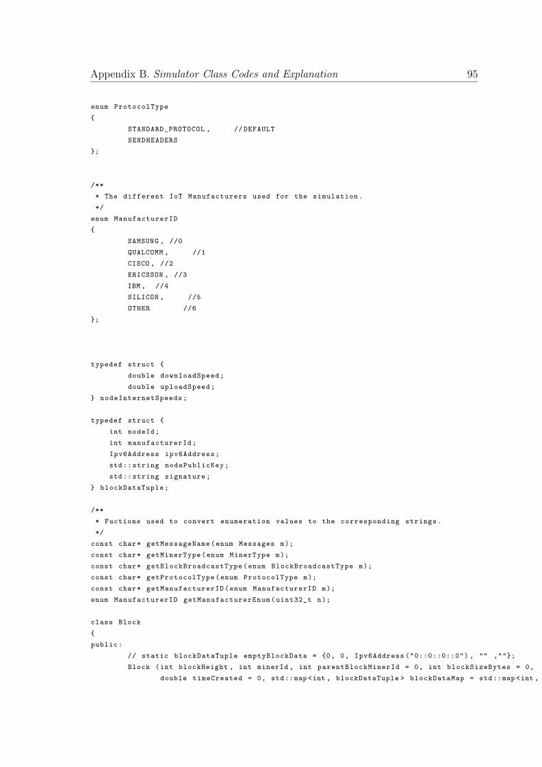
Appendix B. Simulator Class Codes and Explanation 95
enum ProtocolType
{
STANDARD_PROTOCOL , // DEFAULT
SENDHEADERS
};
/**
* The different IoT Manufacturers used for the simulation.
*/
enum ManufacturerID
{
SAMSUNG , //0
QUALCOMM , //1
CISCO , //2
ERICSSON , //3
IBM , //4
SILICON , //5
OTHER //6
};
typedef struct {
double downloadSpeed;
double uploadSpeed;
} nodeInternetSpeeds;
typedef struct {
int nodeId;
int manufacturerId;
Ipv6Address ipv6Address;
std:: string nodePublicKey;
std:: string signature;
} blockDataTuple;
/**
* Fuctions used to convert enumeration values to the corresponding strings.
*/
const char* getMessageName(enum Messages m);
const char* getMinerType(enum MinerType m);
const char* getBlockBroadcastType(enum BlockBroadcastType m);
const char* getProtocolType(enum ProtocolType m);
const char* getManufacturerID(enum ManufacturerID m);
enum ManufacturerID getManufacturerEnum(uint32_t n);
class Block
{
public:
// static blockDataTuple emptyBlockData = {0, 0, Ipv6Address ("0::0::0::0") , "" ,""};
Block (int blockHeight , int minerId , int parentBlockMinerId = 0, int blockSizeBytes = 0,
double timeCreated = 0, std::map <int , blockDataTuple > blockDataMap = std::map <int , blockDataTuple >(), double timeReceived = 0, Ipv6Address receivedFromIpv6Address = Ipv6Address ("0::0::0::0"));
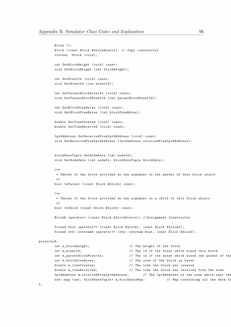
Appendix B. Simulator Class Codes and Explanation 96
Block ();
Block (const Block &blockSource ); // Copy constructor
virtual ~Block (void);
int GetBlockHeight (void) const;
void SetBlockHeight (int blockHeight );
int GetMinerId (void) const;
void SetMinerId (int minerId );
int GetParentBlockMinerId (void) const;
void SetParentBlockMinerId (int parentBlockMinerId );
int GetBlockSizeBytes (void) const;
void SetBlockSizeBytes (int blockSizeBytes );
double GetTimeCreated (void) const;
double GetTimeReceived (void) const;
Ipv6Address GetReceivedFromIpv6Address (void) const;
void SetReceivedFromIpv6Address (Ipv6Address receivedFromIpv6Address );
blockDataTuple GetNodeData (int nodeId );
void SetNodeData (int nodeId , blockDataTuple blockData );
/**
* Checks if the block provided as the argument is the parent of this block object
*/
bool IsParent (const Block &block) const;
/**
* Checks if the block provided as the argument is a child of this block object
*/
bool IsChild (const Block &block) const;
Block& operator= (const Block &blockSource ); // Assignment Constructor
friend bool operator == (const Block &block1 , const Block &block2 );
friend std:: ostream& operator << (std:: ostream &out , const Block &block);
protected:
int m_blockHeight; // The height of the block
int m_minerId; // The id of the miner which mined this block
int m_parentBlockMinerId; // The id of the miner which mined the parent of this block
int m_blockSizeBytes; // The size of the block in bytes
double m_timeCreated; // The time the block was created
double m_timeReceived; // The time the block was received from the node
Ipv6Address m_receivedFromIpv6Address; // The Ipv6Address of the node which sent the block to the receiving node
std::map <int , blockDataTuple > m_blockDataMap; // Map containing all the data for a node.
};
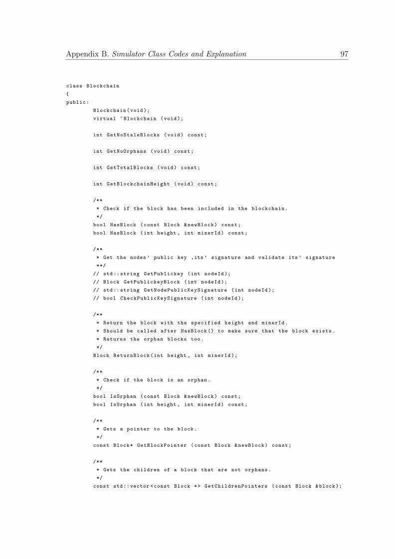
Appendix B. Simulator Class Codes and Explanation 97
class Blockchain
{
public:
Blockchain(void);
virtual ~Blockchain (void);
int GetNoStaleBlocks (void) const;
int GetNoOrphans (void) const;
int GetTotalBlocks (void) const;
int GetBlockchainHeight (void) const;
/**
* Check if the block has been included in the blockchain.
*/
bool HasBlock (const Block &newBlock) const;
bool HasBlock (int height , int minerId) const;
/**
* Get the nodes ’ public key ,its ’ signature and validate its ’ signature
**/
// std:: string GetPublickey (int nodeId );
// Block GetPublickeyBlock (int nodeId );
// std:: string GetNodePublicKeySignature (int nodeId );
// bool CheckPublicKeySignature (int nodeId );
/**
* Return the block with the specified height and minerId.
* Should be called after HasBlock () to make sure that the block exists.
* Returns the orphan blocks too.
*/
Block ReturnBlock(int height , int minerId );
/**
* Check if the block is an orphan.
*/
bool IsOrphan (const Block &newBlock) const;
bool IsOrphan (int height , int minerId) const;
/**
* Gets a pointer to the block.
*/
const Block* GetBlockPointer (const Block &newBlock) const;
/**
* Gets the children of a block that are not orphans.
*/
const std::vector <const Block *> GetChildrenPointers (const Block &block );
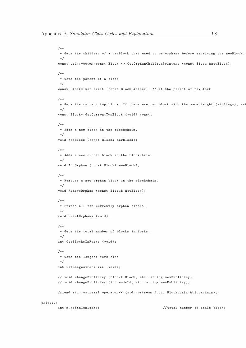
Appendix B. Simulator Class Codes and Explanation 98
/**
* Gets the children of a newBlock that used to be orphans before receiving the newBlock.
*/
const std::vector <const Block *> GetOrphanChildrenPointers (const Block &newBlock );
/**
* Gets the parent of a block
*/
const Block* GetParent (const Block &block ); //Get the parent of newBlock
/**
* Gets the current top block. If there are two block with the same height (siblings), returns the one received first.
*/
const Block* GetCurrentTopBlock (void) const;
/**
* Adds a new block in the blockchain.
*/
void AddBlock (const Block& newBlock );
/**
* Adds a new orphan block in the blockchain.
*/
void AddOrphan (const Block& newBlock );
/**
* Removes a new orphan block in the blockchain.
*/
void RemoveOrphan (const Block& newBlock );
/**
* Prints all the currently orphan blocks.
*/
void PrintOrphans (void);
/**
* Gets the total number of blocks in forks.
*/
int GetBlocksInForks (void);
/**
* Gets the longest fork size
*/
int GetLongestForkSize (void);
// void changePublicKey (Block& Block , std:: string newPublicKey );
// void changePublicKey (int nodeId , std:: string newPublicKey );
friend std:: ostream& operator << (std:: ostream &out , Blockchain &blockchain );
private:
int m_noStaleBlocks; //total number of stale blocks
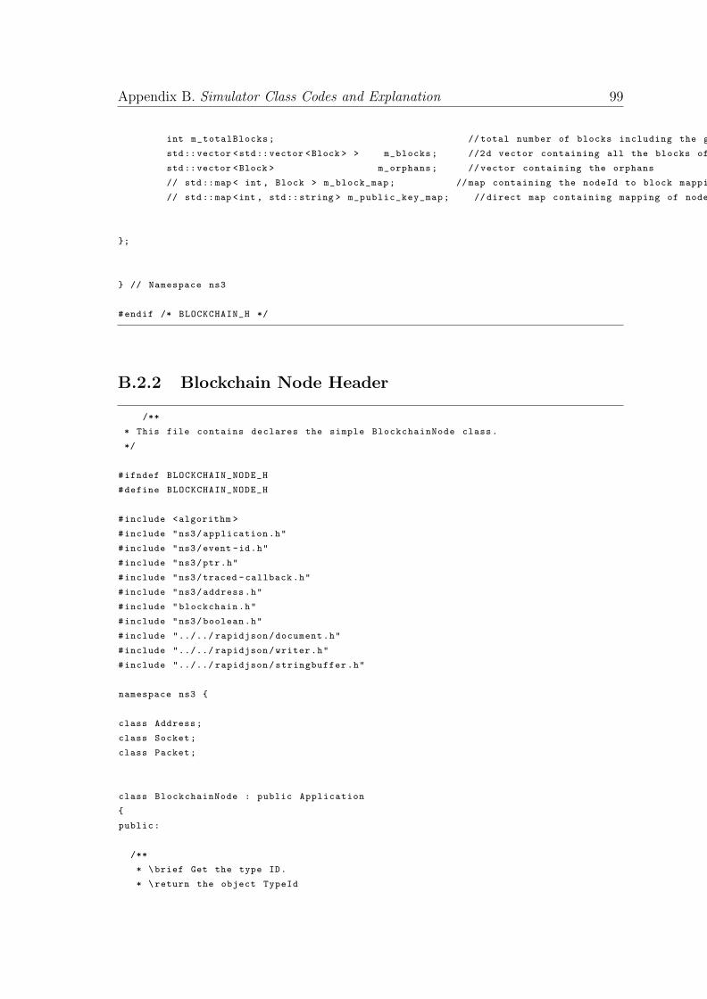
Appendix B. Simulator Class Codes and Explanation 99
int m_totalBlocks; //total number of blocks including the genesis block
std::vector <std::vector <Block > > m_blocks; //2d vector containing all the blocks of the blockchain. (row ->blockHeight , col ->sibling blocks)
std::vector <Block > m_orphans; // vector containing the orphans
// std::map < int , Block > m_block_map; //map containing the nodeId to block mapping
// std::map <int , std::string > m_public_key_map; // direct map containing mapping of node to public key
};
} // Namespace ns3
#endif /* BLOCKCHAIN_H */
B.2.2 Blockchain Node Header
/**
* This file contains declares the simple BlockchainNode class.
*/
#ifndef BLOCKCHAIN_NODE_H
#define BLOCKCHAIN_NODE_H
#include <algorithm >
#include "ns3/application.h"
#include "ns3/event -id.h"
#include "ns3/ptr.h"
#include "ns3/traced -callback.h"
#include "ns3/address.h"
#include "blockchain.h"
#include "ns3/boolean.h"
#include "../../ rapidjson/document.h"
#include "../../ rapidjson/writer.h"
#include "../../ rapidjson/stringbuffer.h"
namespace ns3 {
class Address;
class Socket;
class Packet;
class BlockchainNode : public Application
{
public:
/**
* \brief Get the type ID.
* \return the object TypeId
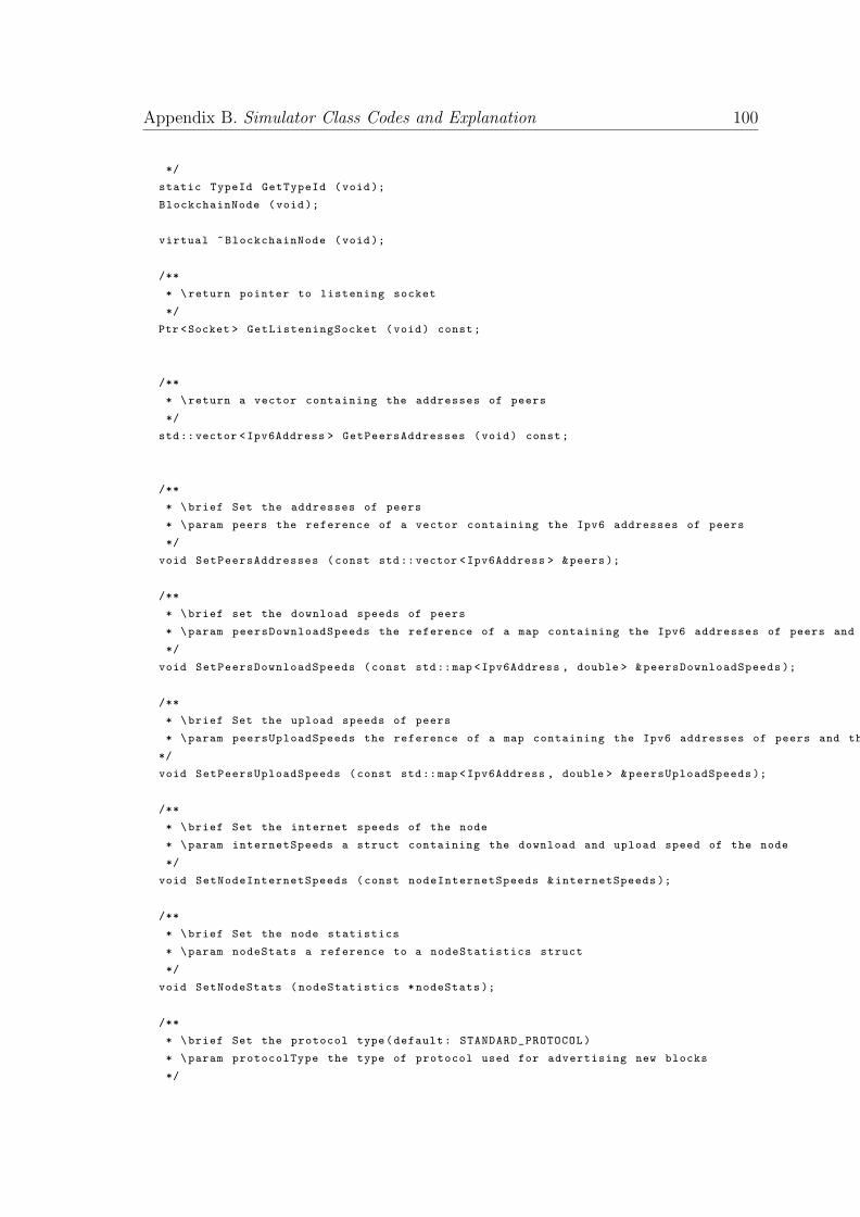
Appendix B. Simulator Class Codes and Explanation 100
*/
static TypeId GetTypeId (void);
BlockchainNode (void);
virtual ~BlockchainNode (void);
/**
* \return pointer to listening socket
*/
Ptr <Socket > GetListeningSocket (void) const;
/**
* \return a vector containing the addresses of peers
*/
std::vector <Ipv6Address > GetPeersAddresses (void) const;
/**
* \brief Set the addresses of peers
* \param peers the reference of a vector containing the Ipv6 addresses of peers
*/
void SetPeersAddresses (const std::vector <Ipv6Address > &peers);
/**
* \brief set the download speeds of peers
* \param peersDownloadSpeeds the reference of a map containing the Ipv6 addresses of peers and their corresponding download speed
*/
void SetPeersDownloadSpeeds (const std::map <Ipv6Address , double > &peersDownloadSpeeds );
/**
* \brief Set the upload speeds of peers
* \param peersUploadSpeeds the reference of a map containing the Ipv6 addresses of peers and their corresponding upload speed
*/
void SetPeersUploadSpeeds (const std::map <Ipv6Address , double > &peersUploadSpeeds );
/**
* \brief Set the internet speeds of the node
* \param internetSpeeds a struct containing the download and upload speed of the node
*/
void SetNodeInternetSpeeds (const nodeInternetSpeeds &internetSpeeds );
/**
* \brief Set the node statistics
* \param nodeStats a reference to a nodeStatistics struct
*/
void SetNodeStats (nodeStatistics *nodeStats );
/**
* \brief Set the protocol type(default: STANDARD_PROTOCOL)
* \param protocolType the type of protocol used for advertising new blocks
*/
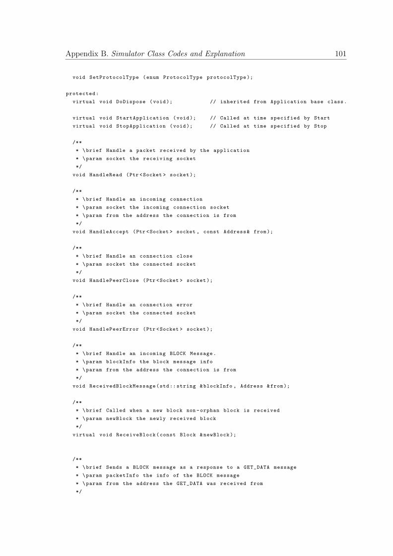
Appendix B. Simulator Class Codes and Explanation 101
void SetProtocolType (enum ProtocolType protocolType );
protected:
virtual void DoDispose (void); // inherited from Application base class.
virtual void StartApplication (void); // Called at time specified by Start
virtual void StopApplication (void); // Called at time specified by Stop
/**
* \brief Handle a packet received by the application
* \param socket the receiving socket
*/
void HandleRead (Ptr <Socket > socket );
/**
* \brief Handle an incoming connection
* \param socket the incoming connection socket
* \param from the address the connection is from
*/
void HandleAccept (Ptr <Socket > socket , const Address& from);
/**
* \brief Handle an connection close
* \param socket the connected socket
*/
void HandlePeerClose (Ptr <Socket > socket );
/**
* \brief Handle an connection error
* \param socket the connected socket
*/
void HandlePeerError (Ptr <Socket > socket );
/**
* \brief Handle an incoming BLOCK Message.
* \param blockInfo the block message info
* \param from the address the connection is from
*/
void ReceivedBlockMessage(std:: string &blockInfo , Address &from);
/**
* \brief Called when a new block non -orphan block is received
* \param newBlock the newly received block
*/
virtual void ReceiveBlock(const Block &newBlock );
/**
* \brief Sends a BLOCK message as a response to a GET_DATA message
* \param packetInfo the info of the BLOCK message
* \param from the address the GET_DATA was received from
*/
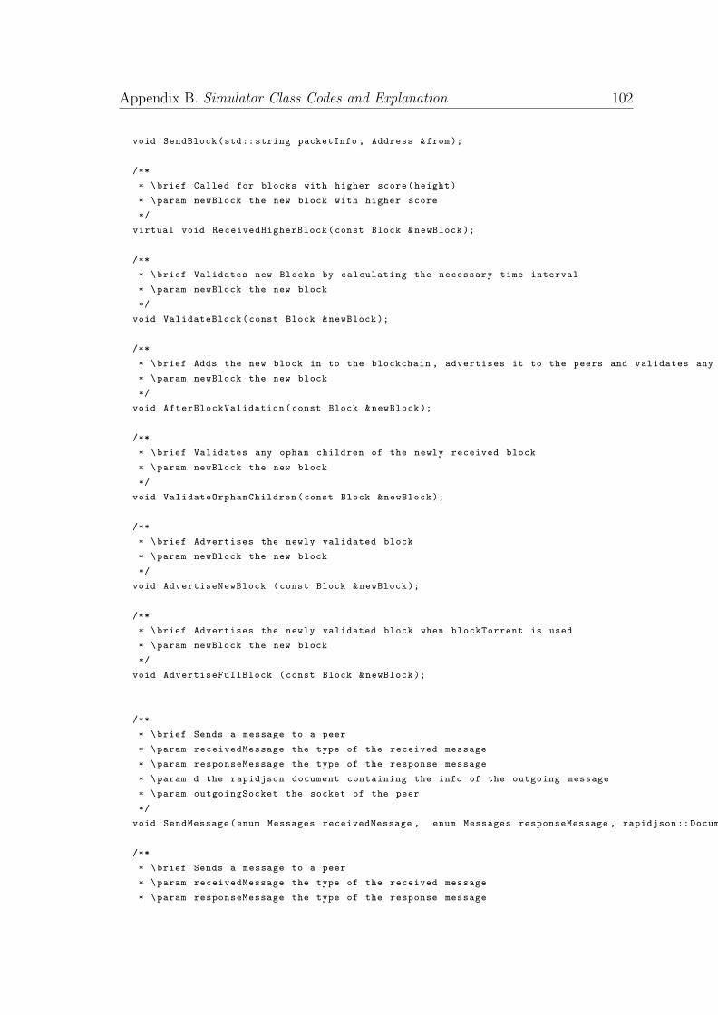
Appendix B. Simulator Class Codes and Explanation 102
void SendBlock(std:: string packetInfo , Address &from);
/**
* \brief Called for blocks with higher score(height)
* \param newBlock the new block with higher score
*/
virtual void ReceivedHigherBlock(const Block &newBlock );
/**
* \brief Validates new Blocks by calculating the necessary time interval
* \param newBlock the new block
*/
void ValidateBlock(const Block &newBlock );
/**
* \brief Adds the new block in to the blockchain , advertises it to the peers and validates any ophan children
* \param newBlock the new block
*/
void AfterBlockValidation(const Block &newBlock );
/**
* \brief Validates any ophan children of the newly received block
* \param newBlock the new block
*/
void ValidateOrphanChildren(const Block &newBlock );
/**
* \brief Advertises the newly validated block
* \param newBlock the new block
*/
void AdvertiseNewBlock (const Block &newBlock );
/**
* \brief Advertises the newly validated block when blockTorrent is used
* \param newBlock the new block
*/
void AdvertiseFullBlock (const Block &newBlock );
/**
* \brief Sends a message to a peer
* \param receivedMessage the type of the received message
* \param responseMessage the type of the response message
* \param d the rapidjson document containing the info of the outgoing message
* \param outgoingSocket the socket of the peer
*/
void SendMessage(enum Messages receivedMessage , enum Messages responseMessage , rapidjson :: Document &d, Ptr <Socket > outgoingSocket );
/**
* \brief Sends a message to a peer
* \param receivedMessage the type of the received message
* \param responseMessage the type of the response message
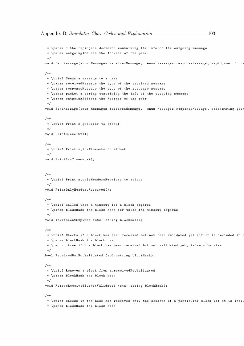
Appendix B. Simulator Class Codes and Explanation 103
* \param d the rapidjson document containing the info of the outgoing message
* \param outgoingAddress the Address of the peer
*/
void SendMessage(enum Messages receivedMessage , enum Messages responseMessage , rapidjson :: Document &d, Address &outgoingAddress );
/**
* \brief Sends a message to a peer
* \param receivedMessage the type of the received message
* \param responseMessage the type of the response message
* \param packet a string containing the info of the outgoing message
* \param outgoingAddress the Address of the peer
*/
void SendMessage(enum Messages receivedMessage , enum Messages responseMessage , std:: string packet , Address &outgoingAddress );
/**
* \brief Print m_queueInv to stdout
*/
void PrintQueueInv ();
/**
* \brief Print m_invTimeouts to stdout
*/
void PrintInvTimeouts ();
/**
* \brief Print m_onlyHeadersReceived to stdout
*/
void PrintOnlyHeadersReceived ();
/**
* \brief Called when a timeout for a block expires
* \param blockHash the block hash for which the timeout expired
*/
void InvTimeoutExpired (std:: string blockHash );
/**
* \brief Checks if a block has been received but not been validated yet (if it is included in m_receivedNotValidated)
* \param blockHash the block hash
* \return true if the block has been received but not validated yet , false otherwise
*/
bool ReceivedButNotValidated (std:: string blockHash );
/**
* \brief Removes a block from m_receivedNotValidated
* \param blockHash the block hash
*/
void RemoveReceivedButNotValidated (std:: string blockHash );
/**
* \brief Checks if the node has received only the headers of a particular block (if it is included in m_onlyHeadersReceived)
* \param blockHash the block hash
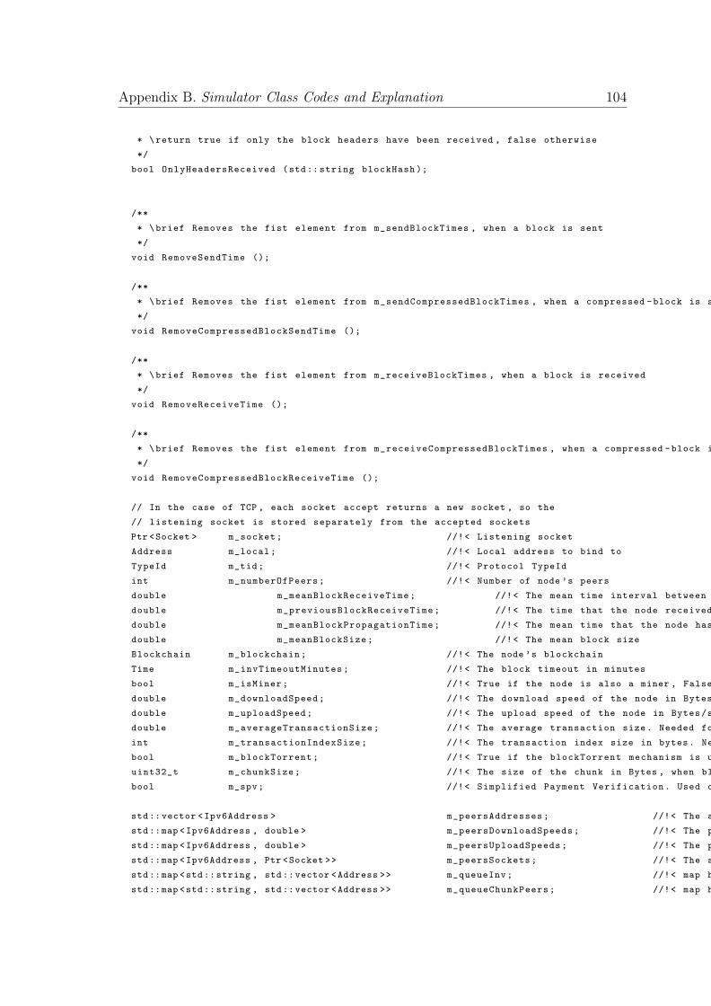
Appendix B. Simulator Class Codes and Explanation 104
* \return true if only the block headers have been received , false otherwise
*/
bool OnlyHeadersReceived (std:: string blockHash );
/**
* \brief Removes the fist element from m_sendBlockTimes , when a block is sent
*/
void RemoveSendTime ();
/**
* \brief Removes the fist element from m_sendCompressedBlockTimes , when a compressed -block is sent
*/
void RemoveCompressedBlockSendTime ();
/**
* \brief Removes the fist element from m_receiveBlockTimes , when a block is received
*/
void RemoveReceiveTime ();
/**
* \brief Removes the fist element from m_receiveCompressedBlockTimes , when a compressed -block is received
*/
void RemoveCompressedBlockReceiveTime ();
// In the case of TCP , each socket accept returns a new socket , so the
// listening socket is stored separately from the accepted sockets
Ptr <Socket > m_socket; //!< Listening socket
Address m_local; //!< Local address to bind to
TypeId m_tid; //!< Protocol TypeId
int m_numberOfPeers; //!< Number of node ’s peers
double m_meanBlockReceiveTime; //!< The mean time interval between two consecutive blocks
double m_previousBlockReceiveTime; //!< The time that the node received the previous block
double m_meanBlockPropagationTime; //!< The mean time that the node has to wait in order to receive a newly mined block
double m_meanBlockSize; //!< The mean block size
Blockchain m_blockchain; //!< The node ’s blockchain
Time m_invTimeoutMinutes; //!< The block timeout in minutes
bool m_isMiner; //!< True if the node is also a miner , False otherwise
double m_downloadSpeed; //!< The download speed of the node in Bytes/s
double m_uploadSpeed; //!< The upload speed of the node in Bytes/s
double m_averageTransactionSize; //!< The average transaction size. Needed for compressed blocks
int m_transactionIndexSize; //!< The transaction index size in bytes. Needed for compressed blocks
bool m_blockTorrent; //!< True if the blockTorrent mechanism is used , False otherwise
uint32_t m_chunkSize; //!< The size of the chunk in Bytes , when blockTorrent is used
bool m_spv; //!< Simplified Payment Verification. Used only in conjuction with blockTorrent
std::vector <Ipv6Address > m_peersAddresses; //!< The addresses of peers
std::map <Ipv6Address , double > m_peersDownloadSpeeds; //!< The peersDownloadSpeeds of channels
std::map <Ipv6Address , double > m_peersUploadSpeeds; //!< The peersUploadSpeeds of channels
std::map <Ipv6Address , Ptr <Socket >> m_peersSockets; //!< The sockets of peers
std::map <std::string , std::vector <Address >> m_queueInv; //!< map holding the addresses of nodes which sent an INV for a particular block
std::map <std::string , std::vector <Address >> m_queueChunkPeers; //!< map holding the addresses of nodes from which we are waiting for a CHUNK , key = block_hash
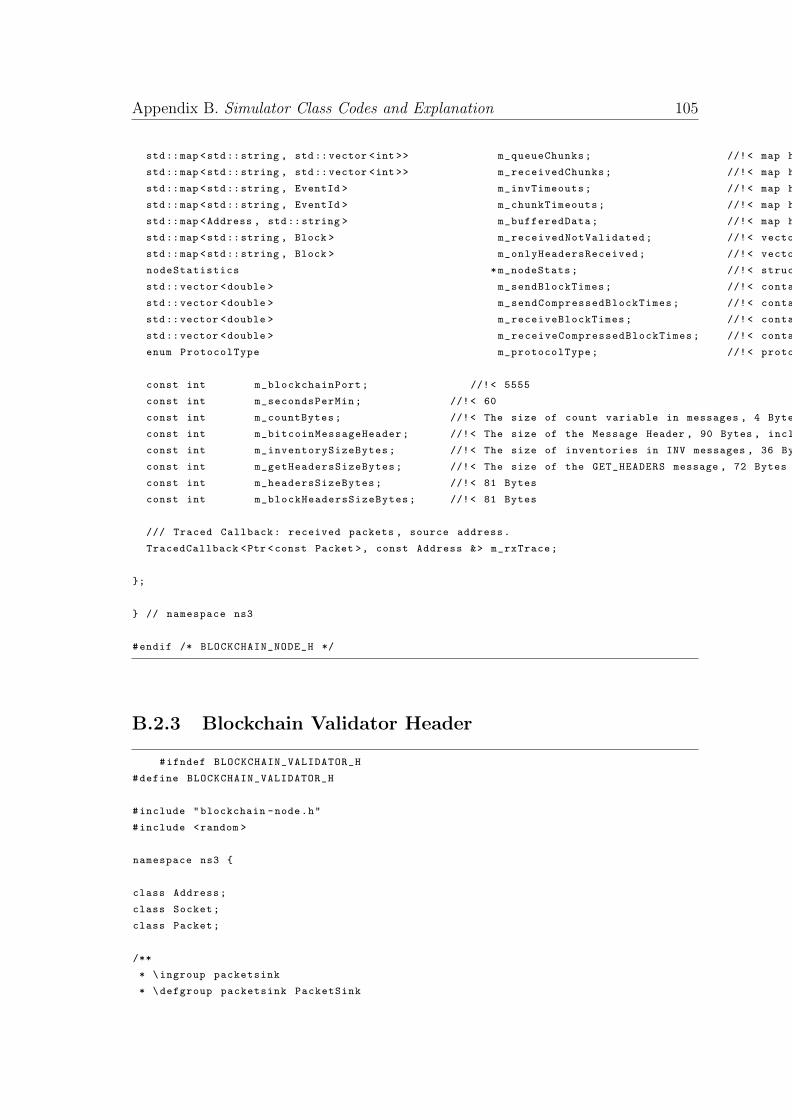
Appendix B. Simulator Class Codes and Explanation 105
std::map <std::string , std::vector <int >> m_queueChunks; //!< map holding the chunks of the blocks which we have not requested yet , key = block_hash
std::map <std::string , std::vector <int >> m_receivedChunks; //!< map holding the chunks of the blocks which we are currently downloading , key = block_hash
std::map <std::string , EventId > m_invTimeouts; //!< map holding the event timeouts of inv messages
std::map <std::string , EventId > m_chunkTimeouts; //!< map holding the event timeouts of chunk messages
std::map <Address , std::string > m_bufferedData; //!< map holding the buffered data from previous handleRead events
std::map <std::string , Block > m_receivedNotValidated; //!< vector holding the received but not yet validated blocks
std::map <std::string , Block > m_onlyHeadersReceived; //!< vector holding the blocks that we know but not received
nodeStatistics *m_nodeStats; //!< struct holding the node stats
std::vector <double > m_sendBlockTimes; //!< contains the times of the next sendBlock events
std::vector <double > m_sendCompressedBlockTimes; //!< contains the times of the next sendBlock events
std::vector <double > m_receiveBlockTimes; //!< contains the times of the next sendBlock events
std::vector <double > m_receiveCompressedBlockTimes; //!< contains the times of the next sendBlock events
enum ProtocolType m_protocolType; //!< protocol type
const int m_blockchainPort; //!< 5555
const int m_secondsPerMin; //!< 60
const int m_countBytes; //!< The size of count variable in messages , 4 Bytes
const int m_bitcoinMessageHeader; //!< The size of the Message Header , 90 Bytes , including both the bitcoinMessageHeaders and the other protocol headers (TCP , IP, Ethernet)
const int m_inventorySizeBytes; //!< The size of inventories in INV messages , 36 Bytes
const int m_getHeadersSizeBytes; //!< The size of the GET_HEADERS message , 72 Bytes
const int m_headersSizeBytes; //!< 81 Bytes
const int m_blockHeadersSizeBytes; //!< 81 Bytes
/// Traced Callback: received packets , source address.
TracedCallback <Ptr <const Packet >, const Address &> m_rxTrace;
};
} // namespace ns3
#endif /* BLOCKCHAIN_NODE_H */
B.2.3 Blockchain Validator Header
#ifndef BLOCKCHAIN_VALIDATOR_H
#define BLOCKCHAIN_VALIDATOR_H
#include "blockchain -node.h"
#include <random >
namespace ns3 {
class Address;
class Socket;
class Packet;
/**
* \ingroup packetsink
* \defgroup packetsink PacketSink
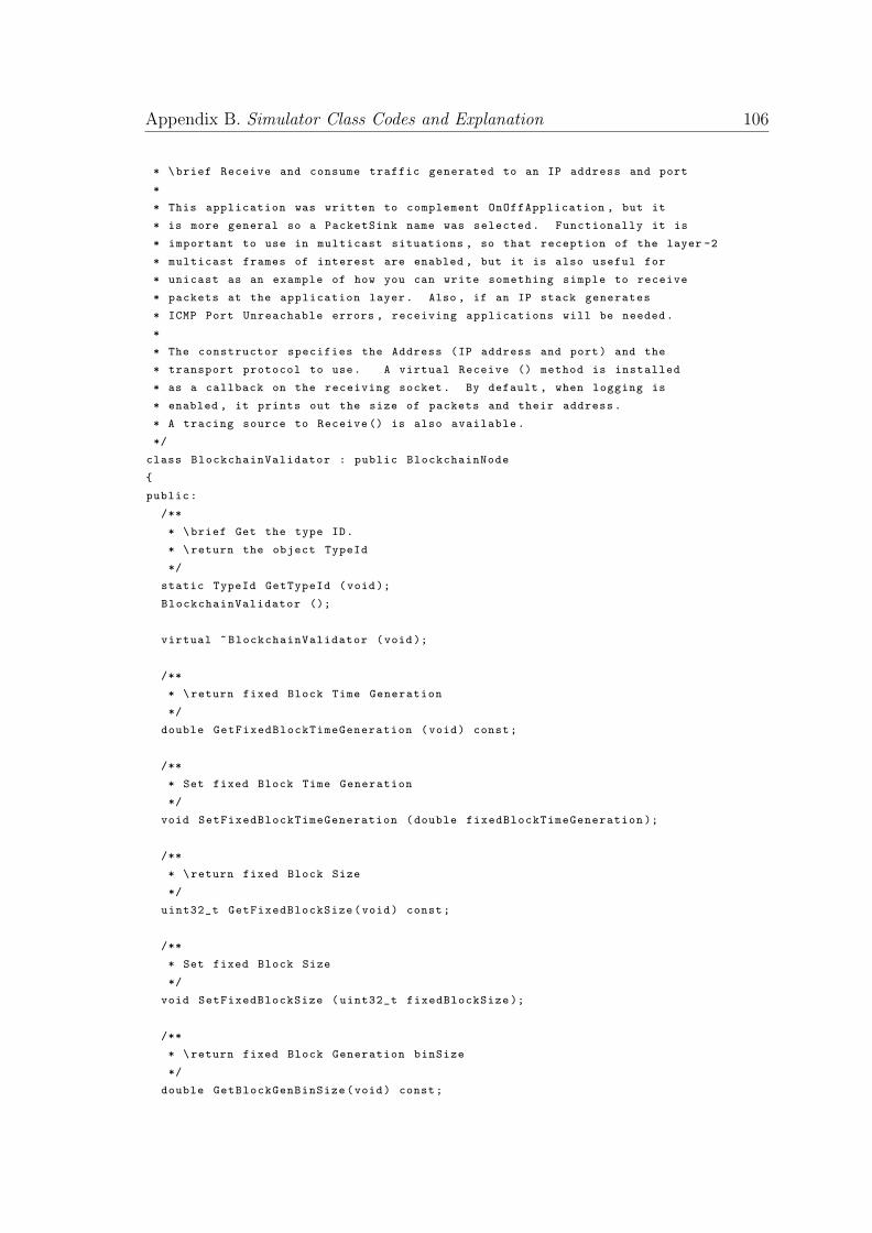
Appendix B. Simulator Class Codes and Explanation 106
* \brief Receive and consume traffic generated to an IP address and port
*
* This application was written to complement OnOffApplication , but it
* is more general so a PacketSink name was selected. Functionally it is
* important to use in multicast situations , so that reception of the layer -2
* multicast frames of interest are enabled , but it is also useful for
* unicast as an example of how you can write something simple to receive
* packets at the application layer. Also , if an IP stack generates
* ICMP Port Unreachable errors , receiving applications will be needed.
*
* The constructor specifies the Address (IP address and port) and the
* transport protocol to use. A virtual Receive () method is installed
* as a callback on the receiving socket. By default , when logging is
* enabled , it prints out the size of packets and their address.
* A tracing source to Receive () is also available.
*/
class BlockchainValidator : public BlockchainNode
{
public:
/**
* \brief Get the type ID.
* \return the object TypeId
*/
static TypeId GetTypeId (void);
BlockchainValidator ();
virtual ~BlockchainValidator (void);
/**
* \return fixed Block Time Generation
*/
double GetFixedBlockTimeGeneration (void) const;
/**
* Set fixed Block Time Generation
*/
void SetFixedBlockTimeGeneration (double fixedBlockTimeGeneration );
/**
* \return fixed Block Size
*/
uint32_t GetFixedBlockSize(void) const;
/**
* Set fixed Block Size
*/
void SetFixedBlockSize (uint32_t fixedBlockSize );
/**
* \return fixed Block Generation binSize
*/
double GetBlockGenBinSize(void) const;
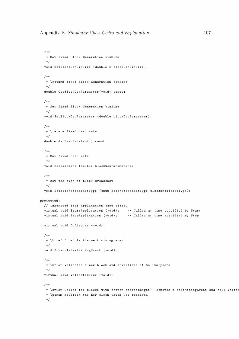
Appendix B. Simulator Class Codes and Explanation 107
/**
* Set fixed Block Generation binSize
*/
void SetBlockGenBinSize (double m_blockGenBinSize );
/**
* \return fixed Block Generation binSize
*/
double GetBlockGenParameter(void) const;
/**
* Set fixed Block Generation binSize
*/
void SetBlockGenParameter (double blockGenParameter );
/**
* \return fixed hash rate
*/
double GetHashRate(void) const;
/**
* Set fixed hash rate
*/
void SetHashRate (double blockGenParameter );
/**
* set the type of block broadcast
*/
void SetBlockBroadcastType (enum BlockBroadcastType blockBroadcastType );
protected:
// inherited from Application base class.
virtual void StartApplication (void); // Called at time specified by Start
virtual void StopApplication (void); // Called at time specified by Stop
virtual void DoDispose (void);
/**
* \brief Schedule the next mining event
*/
void ScheduleNextMiningEvent (void);
/**
* \brief Validates a new block and advertises it to its peers
*/
virtual void ValidateBlock (void);
/**
* \brief Called for blocks with better score(height ). Removes m_nextMiningEvent and call ValidateBlock again.
* \param newBlock the new block which was received
*/
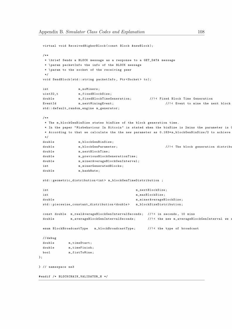
Appendix B. Simulator Class Codes and Explanation 108
virtual void ReceivedHigherBlock(const Block &newBlock );
/**
* \brief Sends a BLOCK message as a response to a GET_DATA message
* \param packetInfo the info of the BLOCK message
* \param to the socket of the receiving peer
*/
void SendBlock(std:: string packetInfo , Ptr <Socket > to);
int m_noMiners;
uint32_t m_fixedBlockSize;
double m_fixedBlockTimeGeneration; //!< Fixed Block Time Generation
EventId m_nextMiningEvent; //!< Event to mine the next block
std:: default_random_engine m_generator;
/**
* The m_blockGenBinSize states binSize of the block generation time.
* In the paper "Misbehaviour In Bitcoin" is stated when the binSize is 2mins the parameter is 0.19.
* According to that we calculate the the new parameter as 0.183* m_blockGenBinSize /2 to achieve better granularity
*/
double m_blockGenBinSize;
double m_blockGenParameter; //!< The block generation distribution parameter
double m_nextBlockTime;
double m_previousBlockGenerationTime;
double m_minerAverageBlockGenInterval;
int m_minerGeneratedBlocks;
double m_hashRate;
std:: geometric_distribution <int > m_blockGenTimeDistribution ;
int m_nextBlockSize;
int m_maxBlockSize;
double m_minerAverageBlockSize;
std:: piecewise_constant_distribution <double > m_blockSizeDistribution;
const double m_realAverageBlockGenIntervalSeconds; //!< in seconds , 10 mins
double m_averageBlockGenIntervalSeconds; //!< the new m_averageBlockGenInterval we set
enum BlockBroadcastType m_blockBroadcastType; //!< the type of broadcast
//debug
double m_timeStart;
double m_timeFinish;
bool m_fistToMine;
};
} // namespace ns3
#endif /* BLOCKCHAIN_VALIDATOR_H */
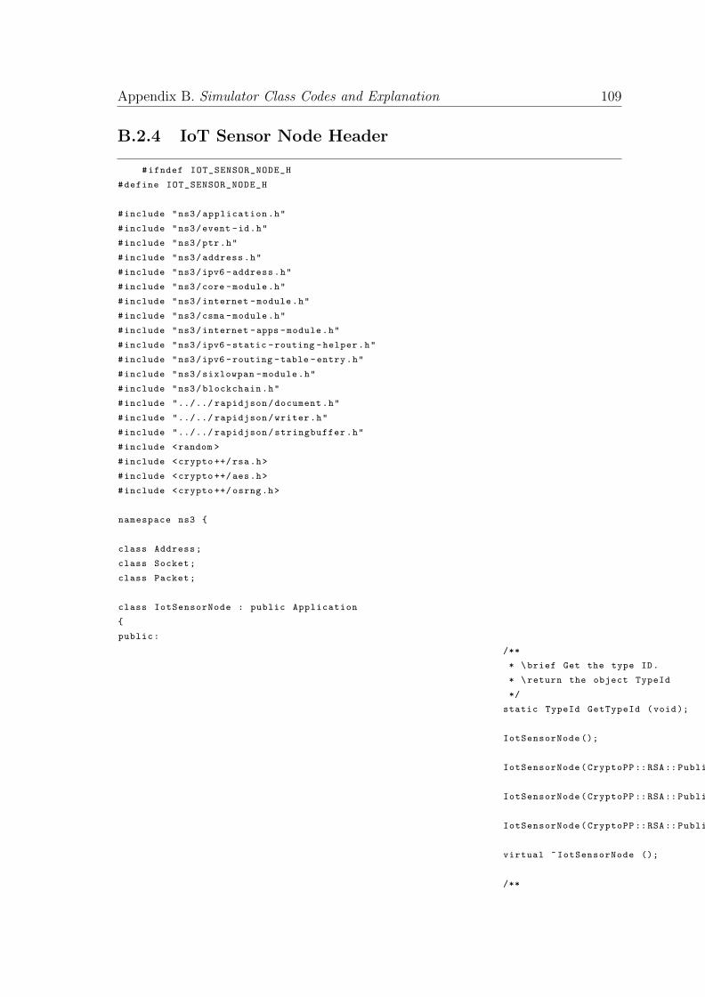
Appendix B. Simulator Class Codes and Explanation 109
B.2.4 IoT Sensor Node Header
#ifndef IOT_SENSOR_NODE_H
#define IOT_SENSOR_NODE_H
#include "ns3/application.h"
#include "ns3/event -id.h"
#include "ns3/ptr.h"
#include "ns3/address.h"
#include "ns3/ipv6 -address.h"
#include "ns3/core -module.h"
#include "ns3/internet -module.h"
#include "ns3/csma -module.h"
#include "ns3/internet -apps -module.h"
#include "ns3/ipv6 -static -routing -helper.h"
#include "ns3/ipv6 -routing -table -entry.h"
#include "ns3/sixlowpan -module.h"
#include "ns3/blockchain.h"
#include "../../ rapidjson/document.h"
#include "../../ rapidjson/writer.h"
#include "../../ rapidjson/stringbuffer.h"
#include <random >
#include <crypto ++/rsa.h>
#include <crypto ++/aes.h>
#include <crypto ++/ osrng.h>
namespace ns3 {
class Address;
class Socket;
class Packet;
class IotSensorNode : public Application
{
public:
/**
* \brief Get the type ID.
* \return the object TypeId
*/
static TypeId GetTypeId (void);
IotSensorNode ();
IotSensorNode(CryptoPP ::RSA:: PublicKey gatewayKey , CryptoPP ::RSA:: PrivateKey privKey );
IotSensorNode(CryptoPP ::RSA:: PublicKey gatewayKey , CryptoPP ::RSA:: PrivateKey privKey ,CryptoPP ::RSA:: PublicKey pubKey );
IotSensorNode(CryptoPP ::RSA:: PublicKey gatewayKey );
virtual ~IotSensorNode ();
/**
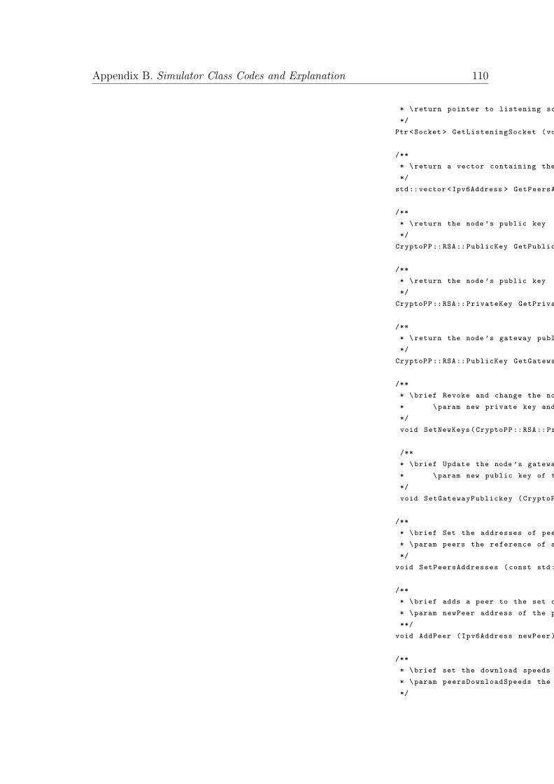
Appendix B. Simulator Class Codes and Explanation 110
* \return pointer to listening socket
*/
Ptr <Socket > GetListeningSocket (void) const;
/**
* \return a vector containing the addresses of peers
*/
std::vector <Ipv6Address > GetPeersAddresses (void) const;
/**
* \return the node ’s public key
*/
CryptoPP ::RSA:: PublicKey GetPublickey (void) const;
/**
* \return the node ’s public key
*/
CryptoPP ::RSA:: PrivateKey GetPrivatekey (void) const;
/**
* \return the node ’s gateway public key
*/
CryptoPP ::RSA:: PublicKey GetGatewayPublickey (void) const;
/**
* \brief Revoke and change the node ’s keys
* \param new private key and public key to be updated.
*/
void SetNewKeys(CryptoPP ::RSA:: PrivateKey newPrivKey , CryptoPP ::RSA:: PublicKey newPublicKey );
/**
* \brief Update the node ’s gateway public key
* \param new public key of the gateway
*/
void SetGatewayPublickey (CryptoPP ::RSA:: PublicKey newGatewayKey );
/**
* \brief Set the addresses of peers
* \param peers the reference of a vector containing the Ipv6 addresses of peers
*/
void SetPeersAddresses (const std::vector <Ipv6Address > &peers);
/**
* \brief adds a peer to the set of peers
* \param newPeer address of the peer to be added
**/
void AddPeer (Ipv6Address newPeer );
/**
* \brief set the download speeds of peers
* \param peersDownloadSpeeds the reference of a map containing the Ipv6 addresses of peers and their corresponding download speed
*/
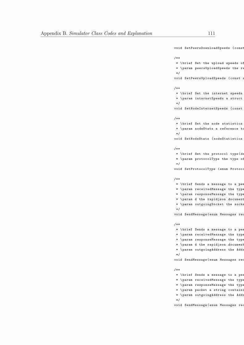
Appendix B. Simulator Class Codes and Explanation 111
void SetPeersDownloadSpeeds (const std::map <Ipv6Address , double > &peersDownloadSpeeds );
/**
* \brief Set the upload speeds of peers
* \param peersUploadSpeeds the reference of a map containing the Ipv6 addresses of peers and their corresponding upload speed
*/
void SetPeersUploadSpeeds (const std::map <Ipv6Address , double > &peersUploadSpeeds );
/**
* \brief Set the internet speeds of the node
* \param internetSpeeds a struct containing the download and upload speed of the node
*/
void SetNodeInternetSpeeds (const nodeInternetSpeeds &internetSpeeds );
/**
* \brief Set the node statistics
* \param nodeStats a reference to a nodeStatistics struct
*/
void SetNodeStats (nodeStatistics *nodeStats );
/**
* \brief Set the protocol type(default: STANDARD_PROTOCOL)
* \param protocolType the type of protocol used for advertising new blocks
*/
void SetProtocolType (enum ProtocolType protocolType );
/**
* \brief Sends a message to a peer
* \param receivedMessage the type of the received message
* \param responseMessage the type of the response message
* \param d the rapidjson document containing the info of the outgoing message
* \param outgoingSocket the socket of the peer
*/
void SendMessage(enum Messages receivedMessage , enum Messages responseMessage , rapidjson :: Document &d, Ptr <Socket > outgoingSocket );
/**
* \brief Sends a message to a peer
* \param receivedMessage the type of the received message
* \param responseMessage the type of the response message
* \param d the rapidjson document containing the info of the outgoing message
* \param outgoingAddress the Address of the peer
*/
void SendMessage(enum Messages receivedMessage , enum Messages responseMessage , rapidjson :: Document &d, Address &outgoingAddress );
/**
* \brief Sends a message to a peer
* \param receivedMessage the type of the received message
* \param responseMessage the type of the response message
* \param packet a string containing the info of the outgoing message
* \param outgoingAddress the Address of the peer
*/
void SendMessage(enum Messages receivedMessage , enum Messages responseMessage , std:: string packet , Address &outgoingAddress );
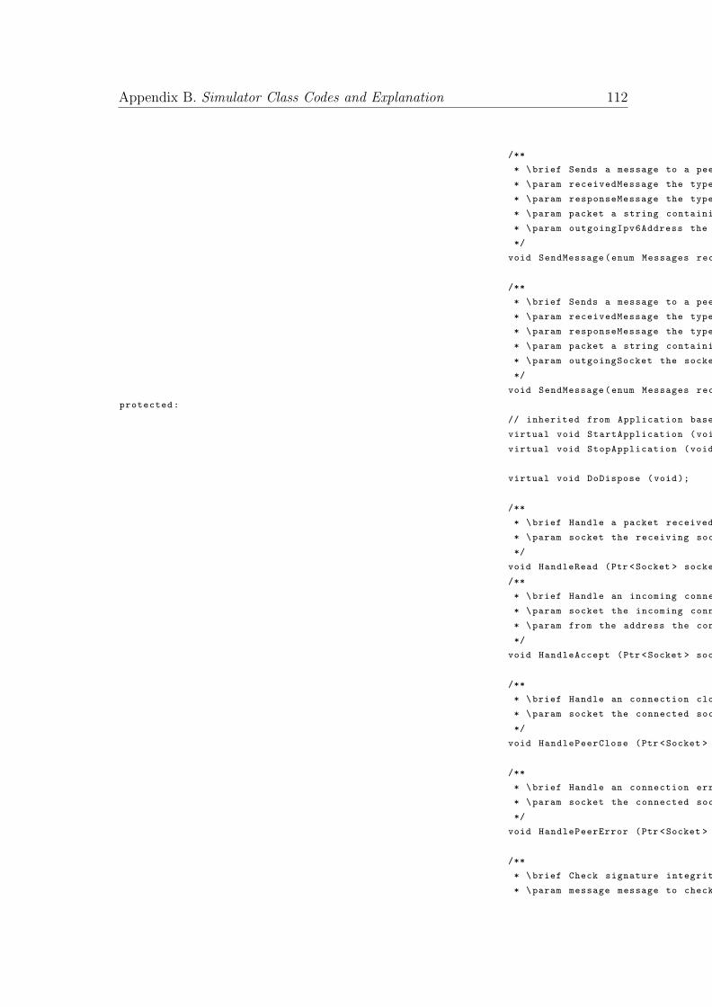
Appendix B. Simulator Class Codes and Explanation 112
/**
* \brief Sends a message to a peer
* \param receivedMessage the type of the received message
* \param responseMessage the type of the response message
* \param packet a string containing the info of the outgoing message
* \param outgoingIpv6Address the Ipv6Address of the peer
*/
void SendMessage(enum Messages receivedMessage , enum Messages responseMessage , std:: string packet , Ipv6Address &outgoingIpv6Address );
/**
* \brief Sends a message to a peer
* \param receivedMessage the type of the received message
* \param responseMessage the type of the response message
* \param packet a string containing the info of the outgoing message
* \param outgoingSocket the socket of the peer
*/
void SendMessage(enum Messages receivedMessage , enum Messages responseMessage , std:: string packet , Ptr <Socket > outgoingSocket );
protected:
// inherited from Application base class.
virtual void StartApplication (void); // Called at time specified by Start
virtual void StopApplication (void); // Called at time specified by Stop
virtual void DoDispose (void);
/**
* \brief Handle a packet received by the application
* \param socket the receiving socket
*/
void HandleRead (Ptr <Socket > socket );
/**
* \brief Handle an incoming connection
* \param socket the incoming connection socket
* \param from the address the connection is from
*/
void HandleAccept (Ptr <Socket > socket , const Address& from);
/**
* \brief Handle an connection close
* \param socket the connected socket
*/
void HandlePeerClose (Ptr <Socket > socket );
/**
* \brief Handle an connection error
* \param socket the connected socket
*/
void HandlePeerError (Ptr <Socket > socket );
/**
* \brief Check signature integrity of a message
* \param message message to check integrity
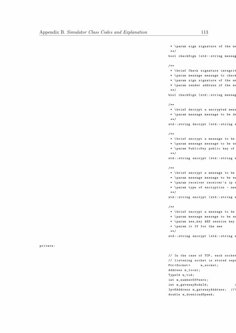
Appendix B. Simulator Class Codes and Explanation 113
* \param sign signature of the message
**/
bool checkSign (std:: string message , std:: string sign);
/**
* \brief Check signature integrity of a message
* \param message message to check integrity
* \param sign signature of the message
* \param sender address of the message sender
**/
bool checkSign (std:: string message , std:: string sign , Ipv6Address sender );
/**
* \brief decrypt a encrypted message
* \param message message to be decrypted
**/
std:: string decrypt (std:: string message );
/**
* \brief encrypt a message to be sent
* \param message message to be encrypted
* \param PublicKey public key of the receiver
**/
std:: string encrypt (std:: string message ,CryptoPP ::RSA:: PublicKey publicKey );
/**
* \brief encrypt a message to be sent
* \param message message to be encrypted
* \param receiver receiver ’s ip address
* \param type of encryption - aes or rsa
**/
std:: string encrypt (std:: string message , Ipv6Address receiver ,int type);
/**
* \brief encrypt a message to be sent
* \param message message to be encrypted
* \param aes_key AES session key
* \param iv IV for the aes
**/
std:: string encrypt (std:: string message , byte* aes_key , byte* iv);
private:
// In the case of TCP , each socket accept returns a new socket , so the
// listening socket is stored separately from the accepted sockets
Ptr <Socket > m_socket; //!< Listening socket
Address m_local; //!< Local address to bind to
TypeId m_tid; //!< Protocol TypeId
int m_numberOfPeers; //!< Number of node ’s peers
int m_gatewayNodeId; //!< Node Id for the gateway
Ipv6Address m_gatewayAddress; //!< Ipv6 address of the gateway
double m_downloadSpeed; //!< The download speed of the node in Bytes/s
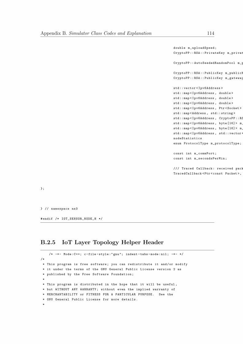
Appendix B. Simulator Class Codes and Explanation 114
double m_uploadSpeed; //!< The upload speed of the node in Bytes/s
CryptoPP ::RSA:: PrivateKey m_privateKey; //!< Private key for the sensor node
CryptoPP :: AutoSeededRandomPool m_prng; //!< PRNG used to generate keys.
CryptoPP ::RSA:: PublicKey m_publicKey; //!< Public key for the sensor node
CryptoPP ::RSA:: PublicKey m_gatewayPublicKey; //!< public key for the gateway
std::vector <Ipv6Address > m_peersAddresses; //!< The addresses of peers
std::map <Ipv6Address , double > m_peersDownloadSpeeds; //!< The peersDownloadSpeeds of channels
std::map <Ipv6Address , double > m_peersUploadSpeeds; //!< The peersUploadSpeeds of channels
std::map <Ipv6Address , double > m_peersSessionKeys; //!< The session keys established with different peers
std::map <Ipv6Address , Ptr <Socket > > m_peersSockets; //!< The sockets of peers
std::map <Address , std::string > m_bufferedData; //!< map holding the buffered data from previous handleRead events
std::map <Ipv6Address , CryptoPP ::RSA::PublicKey > m_publicKeys; //!< map holding the publicKeys for the peers
std::map <Ipv6Address , byte [16]> m_cacheSessionKeys; //!< map holding the cached session keys for peers
std::map <Ipv6Address , byte [16]> m_cacheSessionIVs; //!< map holding the cached session IVs for peers
std::map <Ipv6Address , std::vector <std::string > > m_messages; //!< map holding all the messages from different peers
nodeStatistics *m_nodeStats; //!< struct holding the node stats
enum ProtocolType m_protocolType; //!< protocol type
const int m_commPort; //!< 5555
const int m_secondsPerMin; //!< 60
/// Traced Callback: received packets , source address.
TracedCallback <Ptr <const Packet >, const Address &> m_rxTrace;
};
} // namespace ns3
#endif /* IOT_SENSOR_NODE_H */
B.2.5 IoT Layer Topology Helper Header
/* -*- Mode:C++; c-file -style:"gnu"; indent -tabs -mode:nil; -*- */
/*
* This program is free software; you can redistribute it and/or modify
* it under the terms of the GNU General Public License version 2 as
* published by the Free Software Foundation;
*
* This program is distributed in the hope that it will be useful ,
* but WITHOUT ANY WARRANTY; without even the implied warranty of
* MERCHANTABILITY or FITNESS FOR A PARTICULAR PURPOSE. See the
* GNU General Public License for more details.
*

Appendix B. Simulator Class Codes and Explanation 115
* You should have received a copy of the GNU General Public License
* along with this program; if not , write to the Free Software
* Foundation , Inc., 59 Temple Place , Suite 330, Boston , MA 02111 -1307 USA
*
* Author: Saptarshi Gan <[email protected] >
*/
#ifndef IOT_LAYER_TOPOLOGY_HELPER_H
#define IOT_LAYER_TOPOLOGY_HELPER_H
#include <vector >
#include "internet -stack -helper.h"
#include "point -to-point -helper.h"
#include "ipv4 -address -helper.h"
#include "ipv6 -address -helper.h"
#include "ipv4 -interface -container.h"
#include "ipv6 -interface -container.h"
#include "net -device -container.h"
#include "ipv6 -address -helper -custom.h"
#include "ns3/blockchain.h"
#include <random >
namespace ns3 {
/**
* \ingroup point -to -point -layout
*
* \brief A helper to make it easier to create the discussed layer topology
* with p2p links
*/
class IoTLayerTopologyHelper
{
public:
/**
* Create a IoTLayerTopologyHelper in order to easily create
* discussed layer topology with p2p links
*
*/
IoTLayerTopologyHelper (uint32_t noCpus , uint32_t totalNoNodes , enum ManufacturerID *manufacturers ,
int minConnectionsPerNode , int maxConnectionsPerNode ,
double latencyParetoShapeDivider , uint32_t systemId , std::vector <uint32_t > validators , std::map <uint32_t ,std::vector <uint32_t > > gatewayChildMap , std::map <uint32_t , uint32_t > gatewayValidatorMap , std::map <uint32_t , std::vector <uint32_t > > validatorLinkMap );
~IoTLayerTopologyHelper ();
Ptr <Node > GetNode (uint32_t id);
/**
* This returns an Ipv6 address at the node specified by
* the (row , col) address. Technically , a node will have
* multiple interfaces in the grid; therefore , it also has
* multiple Ipv6 addresses. This method only returns one of
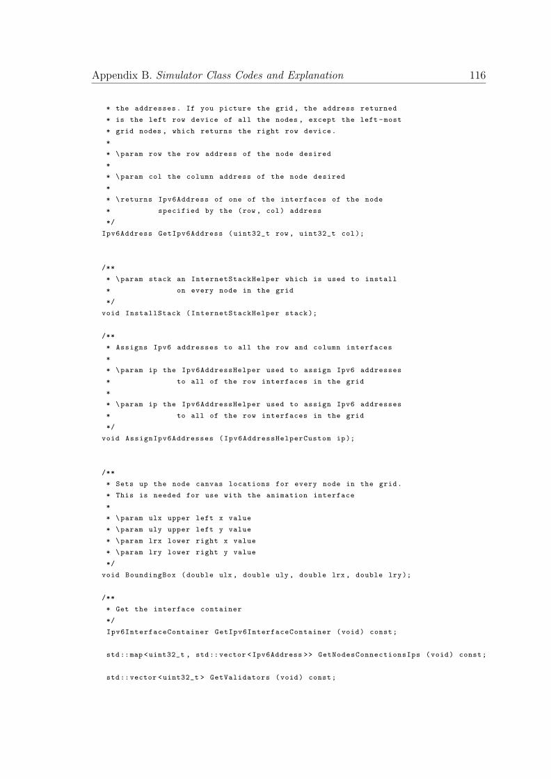
Appendix B. Simulator Class Codes and Explanation 116
* the addresses. If you picture the grid , the address returned
* is the left row device of all the nodes , except the left -most
* grid nodes , which returns the right row device.
*
* \param row the row address of the node desired
*
* \param col the column address of the node desired
*
* \returns Ipv6Address of one of the interfaces of the node
* specified by the (row , col) address
*/
Ipv6Address GetIpv6Address (uint32_t row , uint32_t col);
/**
* \param stack an InternetStackHelper which is used to install
* on every node in the grid
*/
void InstallStack (InternetStackHelper stack);
/**
* Assigns Ipv6 addresses to all the row and column interfaces
*
* \param ip the Ipv6AddressHelper used to assign Ipv6 addresses
* to all of the row interfaces in the grid
*
* \param ip the Ipv6AddressHelper used to assign Ipv6 addresses
* to all of the row interfaces in the grid
*/
void AssignIpv6Addresses (Ipv6AddressHelperCustom ip);
/**
* Sets up the node canvas locations for every node in the grid.
* This is needed for use with the animation interface
*
* \param ulx upper left x value
* \param uly upper left y value
* \param lrx lower right x value
* \param lry lower right y value
*/
void BoundingBox (double ulx , double uly , double lrx , double lry);
/**
* Get the interface container
*/
Ipv6InterfaceContainer GetIpv6InterfaceContainer (void) const;
std::map <uint32_t , std::vector <Ipv6Address >> GetNodesConnectionsIps (void) const;
std::vector <uint32_t > GetValidators (void) const;
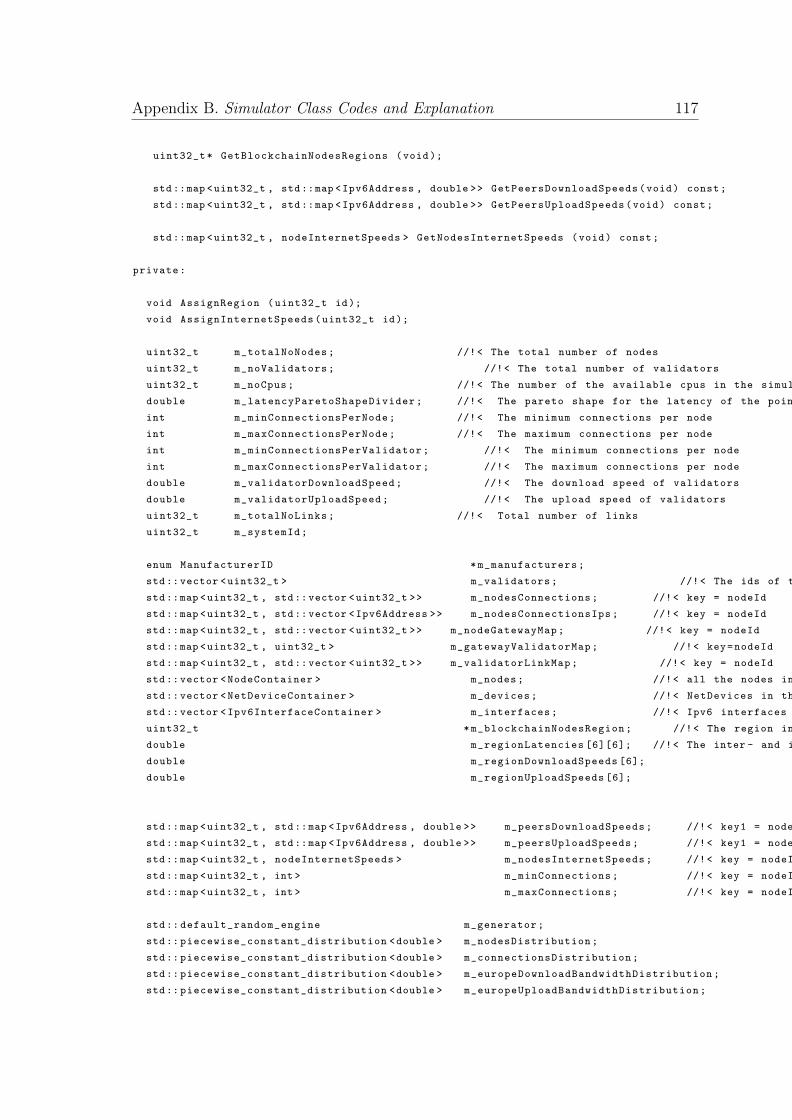
Appendix B. Simulator Class Codes and Explanation 117
uint32_t* GetBlockchainNodesRegions (void);
std::map <uint32_t , std::map <Ipv6Address , double >> GetPeersDownloadSpeeds(void) const;
std::map <uint32_t , std::map <Ipv6Address , double >> GetPeersUploadSpeeds(void) const;
std::map <uint32_t , nodeInternetSpeeds > GetNodesInternetSpeeds (void) const;
private:
void AssignRegion (uint32_t id);
void AssignInternetSpeeds(uint32_t id);
uint32_t m_totalNoNodes; //!< The total number of nodes
uint32_t m_noValidators; //!< The total number of validators
uint32_t m_noCpus; //!< The number of the available cpus in the simulation
double m_latencyParetoShapeDivider; //!< The pareto shape for the latency of the point -to-point links
int m_minConnectionsPerNode; //!< The minimum connections per node
int m_maxConnectionsPerNode; //!< The maximum connections per node
int m_minConnectionsPerValidator; //!< The minimum connections per node
int m_maxConnectionsPerValidator; //!< The maximum connections per node
double m_validatorDownloadSpeed; //!< The download speed of validators
double m_validatorUploadSpeed; //!< The upload speed of validators
uint32_t m_totalNoLinks; //!< Total number of links
uint32_t m_systemId;
enum ManufacturerID *m_manufacturers;
std::vector <uint32_t > m_validators; //!< The ids of the validators
std::map <uint32_t , std::vector <uint32_t >> m_nodesConnections; //!< key = nodeId
std::map <uint32_t , std::vector <Ipv6Address >> m_nodesConnectionsIps; //!< key = nodeId
std::map <uint32_t , std::vector <uint32_t >> m_nodeGatewayMap; //!< key = nodeId
std::map <uint32_t , uint32_t > m_gatewayValidatorMap; //!< key=nodeId
std::map <uint32_t , std::vector <uint32_t >> m_validatorLinkMap; //!< key = nodeId
std::vector <NodeContainer > m_nodes; //!< all the nodes in the network
std::vector <NetDeviceContainer > m_devices; //!< NetDevices in the network
std::vector <Ipv6InterfaceContainer > m_interfaces; //!< Ipv6 interfaces in the network
uint32_t *m_blockchainNodesRegion; //!< The region in which the blockchain nodes are located
double m_regionLatencies [6][6]; //!< The inter - and intra -region latencies
double m_regionDownloadSpeeds [6];
double m_regionUploadSpeeds [6];
std::map <uint32_t , std::map <Ipv6Address , double >> m_peersDownloadSpeeds; //!< key1 = nodeId , key2 = Ipv6Address of peer
std::map <uint32_t , std::map <Ipv6Address , double >> m_peersUploadSpeeds; //!< key1 = nodeId , key2 = Ipv6Address of peer
std::map <uint32_t , nodeInternetSpeeds > m_nodesInternetSpeeds; //!< key = nodeId
std::map <uint32_t , int > m_minConnections; //!< key = nodeId
std::map <uint32_t , int > m_maxConnections; //!< key = nodeId
std:: default_random_engine m_generator;
std:: piecewise_constant_distribution <double > m_nodesDistribution;
std:: piecewise_constant_distribution <double > m_connectionsDistribution;
std:: piecewise_constant_distribution <double > m_europeDownloadBandwidthDistribution;
std:: piecewise_constant_distribution <double > m_europeUploadBandwidthDistribution;
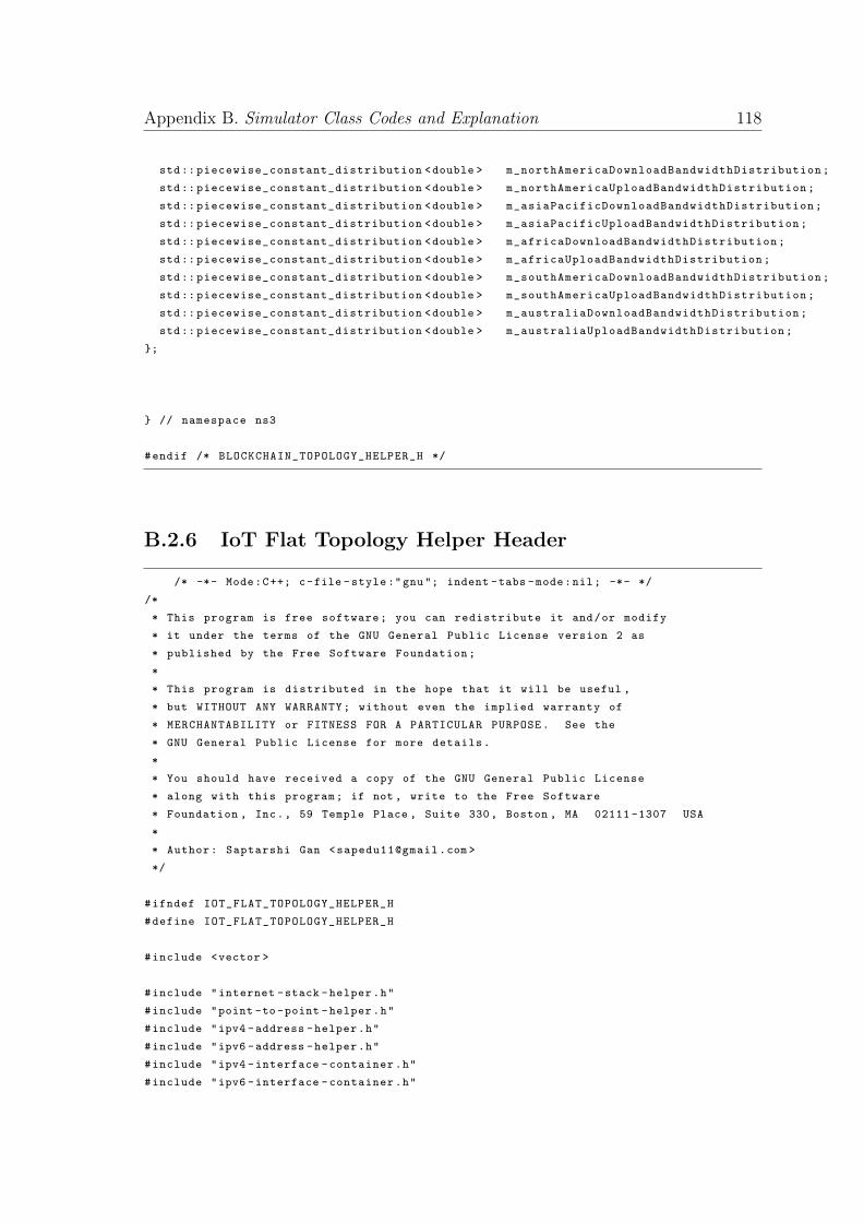
Appendix B. Simulator Class Codes and Explanation 118
std:: piecewise_constant_distribution <double > m_northAmericaDownloadBandwidthDistribution;
std:: piecewise_constant_distribution <double > m_northAmericaUploadBandwidthDistribution;
std:: piecewise_constant_distribution <double > m_asiaPacificDownloadBandwidthDistribution;
std:: piecewise_constant_distribution <double > m_asiaPacificUploadBandwidthDistribution;
std:: piecewise_constant_distribution <double > m_africaDownloadBandwidthDistribution;
std:: piecewise_constant_distribution <double > m_africaUploadBandwidthDistribution;
std:: piecewise_constant_distribution <double > m_southAmericaDownloadBandwidthDistribution;
std:: piecewise_constant_distribution <double > m_southAmericaUploadBandwidthDistribution;
std:: piecewise_constant_distribution <double > m_australiaDownloadBandwidthDistribution;
std:: piecewise_constant_distribution <double > m_australiaUploadBandwidthDistribution;
};
} // namespace ns3
#endif /* BLOCKCHAIN_TOPOLOGY_HELPER_H */
B.2.6 IoT Flat Topology Helper Header
/* -*- Mode:C++; c-file -style:"gnu"; indent -tabs -mode:nil; -*- */
/*
* This program is free software; you can redistribute it and/or modify
* it under the terms of the GNU General Public License version 2 as
* published by the Free Software Foundation;
*
* This program is distributed in the hope that it will be useful ,
* but WITHOUT ANY WARRANTY; without even the implied warranty of
* MERCHANTABILITY or FITNESS FOR A PARTICULAR PURPOSE. See the
* GNU General Public License for more details.
*
* You should have received a copy of the GNU General Public License
* along with this program; if not , write to the Free Software
* Foundation , Inc., 59 Temple Place , Suite 330, Boston , MA 02111 -1307 USA
*
* Author: Saptarshi Gan <[email protected] >
*/
#ifndef IOT_FLAT_TOPOLOGY_HELPER_H
#define IOT_FLAT_TOPOLOGY_HELPER_H
#include <vector >
#include "internet -stack -helper.h"
#include "point -to-point -helper.h"
#include "ipv4 -address -helper.h"
#include "ipv6 -address -helper.h"
#include "ipv4 -interface -container.h"
#include "ipv6 -interface -container.h"
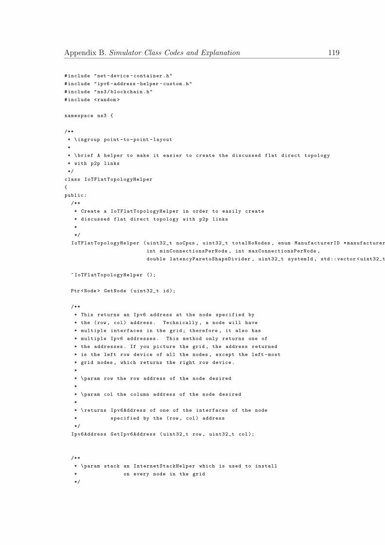
Appendix B. Simulator Class Codes and Explanation 119
#include "net -device -container.h"
#include "ipv6 -address -helper -custom.h"
#include "ns3/blockchain.h"
#include <random >
namespace ns3 {
/**
* \ingroup point -to -point -layout
*
* \brief A helper to make it easier to create the discussed flat direct topology
* with p2p links
*/
class IoTFlatTopologyHelper
{
public:
/**
* Create a IoTFlatTopologyHelper in order to easily create
* discussed flat direct topology with p2p links
*
*/
IoTFlatTopologyHelper (uint32_t noCpus , uint32_t totalNoNodes , enum ManufacturerID *manufacturers ,
int minConnectionsPerNode , int maxConnectionsPerNode ,
double latencyParetoShapeDivider , uint32_t systemId , std::vector <uint32_t > validators , std::map <uint32_t , uint32_t > iotValidatorMap , std::map <uint32_t , std::vector <uint32_t > > validatorLinkMap );
~IoTFlatTopologyHelper ();
Ptr <Node > GetNode (uint32_t id);
/**
* This returns an Ipv6 address at the node specified by
* the (row , col) address. Technically , a node will have
* multiple interfaces in the grid; therefore , it also has
* multiple Ipv6 addresses. This method only returns one of
* the addresses. If you picture the grid , the address returned
* is the left row device of all the nodes , except the left -most
* grid nodes , which returns the right row device.
*
* \param row the row address of the node desired
*
* \param col the column address of the node desired
*
* \returns Ipv6Address of one of the interfaces of the node
* specified by the (row , col) address
*/
Ipv6Address GetIpv6Address (uint32_t row , uint32_t col);
/**
* \param stack an InternetStackHelper which is used to install
* on every node in the grid
*/
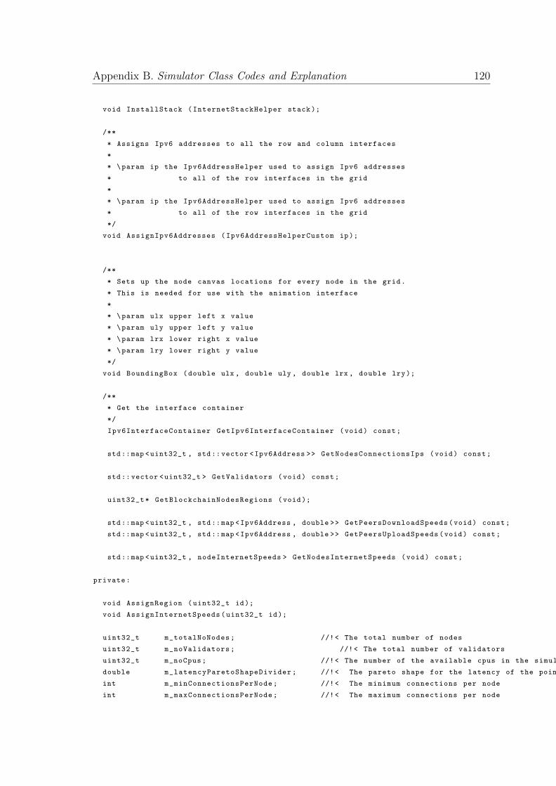
Appendix B. Simulator Class Codes and Explanation 120
void InstallStack (InternetStackHelper stack);
/**
* Assigns Ipv6 addresses to all the row and column interfaces
*
* \param ip the Ipv6AddressHelper used to assign Ipv6 addresses
* to all of the row interfaces in the grid
*
* \param ip the Ipv6AddressHelper used to assign Ipv6 addresses
* to all of the row interfaces in the grid
*/
void AssignIpv6Addresses (Ipv6AddressHelperCustom ip);
/**
* Sets up the node canvas locations for every node in the grid.
* This is needed for use with the animation interface
*
* \param ulx upper left x value
* \param uly upper left y value
* \param lrx lower right x value
* \param lry lower right y value
*/
void BoundingBox (double ulx , double uly , double lrx , double lry);
/**
* Get the interface container
*/
Ipv6InterfaceContainer GetIpv6InterfaceContainer (void) const;
std::map <uint32_t , std::vector <Ipv6Address >> GetNodesConnectionsIps (void) const;
std::vector <uint32_t > GetValidators (void) const;
uint32_t* GetBlockchainNodesRegions (void);
std::map <uint32_t , std::map <Ipv6Address , double >> GetPeersDownloadSpeeds(void) const;
std::map <uint32_t , std::map <Ipv6Address , double >> GetPeersUploadSpeeds(void) const;
std::map <uint32_t , nodeInternetSpeeds > GetNodesInternetSpeeds (void) const;
private:
void AssignRegion (uint32_t id);
void AssignInternetSpeeds(uint32_t id);
uint32_t m_totalNoNodes; //!< The total number of nodes
uint32_t m_noValidators; //!< The total number of validators
uint32_t m_noCpus; //!< The number of the available cpus in the simulation
double m_latencyParetoShapeDivider; //!< The pareto shape for the latency of the point -to-point links
int m_minConnectionsPerNode; //!< The minimum connections per node
int m_maxConnectionsPerNode; //!< The maximum connections per node
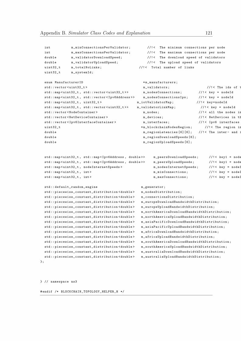
Appendix B. Simulator Class Codes and Explanation 121
int m_minConnectionsPerValidator; //!< The minimum connections per node
int m_maxConnectionsPerValidator; //!< The maximum connections per node
double m_validatorDownloadSpeed; //!< The download speed of validators
double m_validatorUploadSpeed; //!< The upload speed of validators
uint32_t m_totalNoLinks; //!< Total number of links
uint32_t m_systemId;
enum ManufacturerID *m_manufacturers;
std::vector <uint32_t > m_validators; //!< The ids of the validators
std::map <uint32_t , std::vector <uint32_t >> m_nodesConnections; //!< key = nodeId
std::map <uint32_t , std::vector <Ipv6Address >> m_nodesConnectionsIps; //!< key = nodeId
std::map <uint32_t , uint32_t > m_iotValidatorMap; //!< key=nodeId
std::map <uint32_t , std::vector <uint32_t >> m_validatorLinkMap; //!< key = nodeId
std::vector <NodeContainer > m_nodes; //!< all the nodes in the network
std::vector <NetDeviceContainer > m_devices; //!< NetDevices in the network
std::vector <Ipv6InterfaceContainer > m_interfaces; //!< Ipv6 interfaces in the network
uint32_t *m_blockchainNodesRegion; //!< The region in which the blockchain nodes are located
double m_regionLatencies [6][6]; //!< The inter - and intra -region latencies
double m_regionDownloadSpeeds [6];
double m_regionUploadSpeeds [6];
std::map <uint32_t , std::map <Ipv6Address , double >> m_peersDownloadSpeeds; //!< key1 = nodeId , key2 = Ipv6Address of peer
std::map <uint32_t , std::map <Ipv6Address , double >> m_peersUploadSpeeds; //!< key1 = nodeId , key2 = Ipv6Address of peer
std::map <uint32_t , nodeInternetSpeeds > m_nodesInternetSpeeds; //!< key = nodeId
std::map <uint32_t , int > m_minConnections; //!< key = nodeId
std::map <uint32_t , int > m_maxConnections; //!< key = nodeId
std:: default_random_engine m_generator;
std:: piecewise_constant_distribution <double > m_nodesDistribution;
std:: piecewise_constant_distribution <double > m_connectionsDistribution;
std:: piecewise_constant_distribution <double > m_europeDownloadBandwidthDistribution;
std:: piecewise_constant_distribution <double > m_europeUploadBandwidthDistribution;
std:: piecewise_constant_distribution <double > m_northAmericaDownloadBandwidthDistribution;
std:: piecewise_constant_distribution <double > m_northAmericaUploadBandwidthDistribution;
std:: piecewise_constant_distribution <double > m_asiaPacificDownloadBandwidthDistribution;
std:: piecewise_constant_distribution <double > m_asiaPacificUploadBandwidthDistribution;
std:: piecewise_constant_distribution <double > m_africaDownloadBandwidthDistribution;
std:: piecewise_constant_distribution <double > m_africaUploadBandwidthDistribution;
std:: piecewise_constant_distribution <double > m_southAmericaDownloadBandwidthDistribution;
std:: piecewise_constant_distribution <double > m_southAmericaUploadBandwidthDistribution;
std:: piecewise_constant_distribution <double > m_australiaDownloadBandwidthDistribution;
std:: piecewise_constant_distribution <double > m_australiaUploadBandwidthDistribution;
};
} // namespace ns3
#endif /* BLOCKCHAIN_TOPOLOGY_HELPER_H */
Appendix B. Simulator Class Codes and Explanation 122
The entire code is available at Github
Bibliography
[1] Wikipedia. Mirai (malware). https://en.wikipedia.org/wiki/Mirai_
(malware), 2017.
[2] Ali Dorri, Salil S Kanhere, Raja Jurdak, and Praveen Gauravaram. Blockchain
for iot security and privacy: The case study of a smart home. In Pervasive
Computing and Communications Workshops (PerCom Workshops), 2017 IEEE
International Conference on, pages 618–623. IEEE, 2017.
[3] Andreas M. Antonopoulos. Mastering bitcoin. http://chimera.labs.
oreilly.com/books/1234000001802/ch07.html, 2014.
[4] NSNAM. Topology generator. https://www.nsnam.org/wiki/Topology_
Generator, 2017.
[5] Wikipedia. Diffie–hellman key exchange. https://en.wikipedia.org/wiki/
Diffie-Hellman_key_exchange, 2017.
[6] Wikipedia. Internet of things. https://en.wikipedia.org/wiki/Internet_
of_things, 2017.
[7] Nathan Eddy. Gartner: 21 billion iot devices to invade by 2020. Information-
Week, Nov, 10, 2015.
[8] Digital Attack Map. What is a ddos attack? http://www.digitalattackmap.
com/understanding-ddos/, 2017.
[9] Eyal Ronen, Colin O’Flynn, Adi Shamir, and Achi-Or Weingarten. Iot goes
nuclear: Creating a zigbee chain reaction. Weizmann Institute of Science,
Tech. Rep, 2016.
123
Bibliography 124
[10] Adam Dunkels, Oliver Schmidt, Niclas Finne, Joakim Eriksson, Fredrik
Osterlind, Nicolas Tsiftes, and Mathilde Durvy. The contiki os: The oper-
ating system for the internet of things. Online], at http://www. contikios. org,
2011.
[11] Xuezhi Zeng, Saurabh Kumar Garg, Peter Strazdins, Prem Prakash Jayaraman,
Dimitrios Georgakopoulos, and Rajiv Ranjan. Iotsim: A simulator for analysing
iot applications. Journal of Systems Architecture, 72:93–107, 2017.
[12] Rodrigo N. Calheiros, Rajiv Ranjan, Anton Beloglazov, Cesar A. F. De Rose,
and Rajkumar Buyya. Cloudsim: a toolkit for modeling and simulation of cloud
computing environments and evaluation of resource provisioning algorithms.
Software: Practice and Experience, 41(1):23–50, 2011.
[13] Andras Varga and Rudolf Hornig. An overview of the omnet++ simulation
environment. In Proceedings of the 1st international conference on Simula-
tion tools and techniques for communications, networks and systems & work-
shops, page 60. ICST (Institute for Computer Sciences, Social-Informatics and
Telecommunications Engineering), 2008.
[14] Thomas R Henderson, Mathieu Lacage, George F Riley, C Dowell, and
J Kopena. Network simulations with the ns-3 simulator. SIGCOMM demon-
stration, 14, 2008.
[15] Riverbed Technologies. Opnet simulator. https://www.riverbed.com/in/
products/steelcentral/opnet.html, 2017.
[16] Tetcos. Netsim emulator. http://tetcos.com/, 2017.
[17] Jeff Ahrenholz, Claudiu Danilov, Thomas R Henderson, and Jae H Kim. Core:
A real-time network emulator. In Military Communications Conference, 2008.
MILCOM 2008. IEEE, pages 1–7. IEEE, 2008.
[18] Konstantinos Christidis and Michael Devetsikiotis. Blockchains and smart con-
tracts for the internet of things. IEEE Access, 4:2292–2303, 2016.
[19] Slock.it. Slock.it—blockchain + iot. https://slock.it/faq.md, 2017.
Bibliography 125
[20] Mayra Samaniego and Ralph Deters. Hosting virtual iot resources on edge-hosts
with blockchain. In Computer and Information Technology (CIT), 2016 IEEE
International Conference on, pages 116–119. IEEE, 2016.
[21] Yu Zhang and Jiangtao Wen. The iot electric business model: Using blockchain
technology for the internet of things. Peer-to-Peer Networking and Applications,
10(4):983–994, 2017.
[22] Uday Kumar, Tuhin Borgohain, and Sugata Sanyal. Comparative analysis of
cryptography library in iot. arXiv preprint arXiv:1504.04306, 2015.
[23] Satoshi Nakamoto. Bitcoin: A peer-to-peer electronic cash system, 2008.
[24] Wikipedia. Blockchain. https://en.wikipedia.org/wiki/Blockchain, 2017.
[25] Stephen Armstrong. Move over bitcoin, the blockchain is only just getting
started. http://www.wired.co.uk/article/unlock-the-blockchain, 2016.
[26] Ray Patterson. Alternatives for proof of work, part
1: Proof of stake. https://bytecoin.org/blog/
proof-of-activity-proof-of-burn-proof-of-capacity/, 2015.
[27] John R Douceur. The sybil attack. In International Workshop on Peer-to-Peer
Systems, pages 251–260. Springer, 2002.
[28] Wikipedia. Replay attack. https://en.wikipedia.org/wiki/Replay_
attack, 2017.
[29] Harvey S. James Jr. The trust paradox: a survey of economic inquiries into the
nature of trust and trustworthiness. Journal of Economic Behavior & Organi-
zation, 47(3):291 – 307, 2002.
[30] Namecoin. Namecoin. https://namecoin.org/, 2017.
[31] Conner Fromknecht, Dragos Velicanu, and Sophia Yakoubov. Certcoin: A
namecoin based decentralized authentication system 6.857 class project. 2014.
[32] Roel Maes. Physically unclonable functions: Constructions, properties and ap-
plications. Springer Science & Business Media, 2013.
Bibliography 126
[33] Intel. Intel R© trusted execution technol-
ogy. https://www.intel.com/content/www/us/en/
architecture-and-technology/trusted-execution-technology/
trusted-execution-technology-security-paper.html, 2017.
[34] ARM. Arm trustzone. https://www.arm.com/products/security-on-arm/
trustzone, 2017.
[35] Arthur Gervais, Ghassan Karame, Karl Wust, Vasileios Glykantzis, Hubert
Ritzdorf, and Srdjan Capkun. On the security and performance of proof of
work blockchains. In Proceedings of the 23nd ACM SIGSAC Conference on
Computer and Communication Security (CCS). ACM, 2016.
[36] Wei Dai. Crypto++ library. https://www.cryptopp.com/, 2017.
[37] Gao Chong, Ling Zhihao, and Yuan Yifeng. The research and implement of
smart home system based on internet of things. In Electronics, Communications
and Control (ICECC), 2011 International Conference on, pages 2944–2947.
IEEE, 2011.
[38] Samsung. Secured communication with the payment net-
works. http://developer.samsung.com/tech-insights/pay/
secured-communication-with-the-payment-networks, 2017.
[39] EO Kiktenko, NO Pozhar, MN Anufriev, AS Trushechkin, RR Yunusov,
YV Kurochkin, AI Lvovsky, and AK Fedorov. Quantum-secured blockchain.
arXiv preprint arXiv:1705.09258, 2017.
[40] Yury Namestnikov Konstantin Zykov Jornt van der Wiel, Vicente Diaz.
Hajime, the mysterious evolving botnet. https://securelist.com/
hajime-the-mysterious-evolving-botnet/78160/, 2017.