Embed Size (px)
Citation preview
Ocean Systems Engineering, Vol. 9, No. 2 (2019) 157-177
DOI: https:// doi.org/10.12989/ose.2019.9.2.157 157
Copyright © 2019 Techno-Press, Ltd.
http://www.techno-press.org/?journal=ose&subpage=7 ISSN: 2093-6702 (Print), 2093-677X (Online)
An investigation into the motion and stability behaviour of a RO-RO vessel
Poonam Mohan and A.P. Shashikala
Department of Civil Engineering, National Institute of Technology, Calicut, India
(Received November 6, 2018, Revised April 10, 2019, Accepted April 11, 2019)
Abstract. Studies on motion response of a vessel is of great interest to researchers, since a long time. But intensive researches on stability of vessel during motion under dynamic conditions are few. A numerical model of vessel is developed and responses are analyzed in head, beam and quartering sea conditions. Variation of response amplitude operator (RAO) of vessel based on Strip Theory for different wave heights is plotted. Validation of results was done experimentally and numerical results was considered to obtain effect of damping on vessel stability. A scale model ratio of 1:125 was used which is suitable for dimensions of wave flume at National Institute of Technology Calicut. Stability chart are developed based on Mathieu‟s equation of stability. Ince-Strutt chart developed can help to capture variations of stability with damping.
Keywords: in-tact stability; Mathieu‟s equation; Response Amplitude Operator (RAO)
1. Introduction
Ships are generally effected by dynamic waves in head, beam and quarter sea condition. During
its static condition, fluctuations in self- weight and buoyancy play a major role. Onset of waves
contributes to dynamic condition of vessel and then stability conditions vary abruptly along with
change in vessel motion. Direction of wave impact and vessel speed influences motion behavior of
vessel.
Ro-Ro (Roll-on/roll-off) vessel has a high risks in design due to less number of internal
bulkheads (Knapp 1995). It has great stability issues even though this ship proved very useful in
terms of speed, cost and time effectiveness. These vessels require proper and careful handling
because it has large deck area with transverse bulkheads which promotes rapid inrush of flood
water and sudden failure on hull. Also, cargo or passenger movements give rise to unanticipated
intact stability loss and listing (Ibrahim and Grace 2010).Huge superstructure of vessel can cause
stability loss due to wind. Loading and unloading process require great attention in stability point
of view. Due to these reasons, change in GM may make vessel fail to satisfy standard regulatory
requirements, leading to collapse of vessel.
By understanding criticality of vessel design, Allianz Global Corporate published a report
namely “Safety and Shipping 1912-2012: from Titanic to Costa Concordia” from studies done by
Cardiff University, which lists casualty in percentage during year 2000-2010 for Cargo Vessels as
Corresponding author, Research Scholar, E-mail: [email protected]
Poonam Mohan and A.P. Shashikala
44.5%, Passengers/General Cargo as 5.2% and Passenger Cruise as 1.1%. From this survey, it is
understood that problem of motion and stability is to be studied even more intensively in case of
Ro-Ro vessel. Many projects were involved in study of variations in motion in intact and damage
stability to harmonize Ro-Ro vessels and to keep rules and regulations updated to recent
unconventional methods. These includes GOALDS, EMSA III, FLOOD-STAND, HARDER,
ROROPROB etc.
Table 1 Nomenclature
Parameters Unit
Centre of gravity CG
Aft Perpendicular AP
Draft at Aft Perpendicular d
Block coefficient CB
Prismatic coefficient CP
Length overall LOA
Length between perpendiculars L PP
Breadth Moulded b
Midship section coefficient CM
Roll ,Pitch radius of gyration Kxx , Kyy
Breadth Moulded b
Amidships section coefficient CM
Water plane coefficient CWP
Height of keel to metacenter KM
Height of keel to C.G KG
Metacentric height GM
Longitudinal position of C.G LCG
Modulus of Elasticity E
Wavelength λ
Wave Frequency ω
Wave encountering frequency ωe
Displacement Δ
Moment of Inertia about roll axis I4
Angle of heel φ
Heave RAO H
Pitch RAO P
Damping Coefficient B
Stiffness Coefficient C
Damping ratio ϵ
Damped frequency of oscillation ωD
Added mass A
External Exciting Force F4
Forward speed V
158
An investigation into the motion and stability behaviour of a RO-RO vessel
The fact that Ro-Ro Vessels are operated at required metacentric height (GM) close to damage
stability requirement (Hanzu 2016) leaves a gap for further research in this area. Stability criteria
should always be governed by intact stability conditions, rather than damage stability conditions.
Fernández (2015) did stability investigation on damaged ships and found that it is more complex
phenomenon.
Experimental and numerical investigations have been carried out to estimate motion behavior
of vessel. Wave height is varied and type of wave used is small regular waves suitable for model
length. Anastopoulos and Spyrou (2016) performed dynamic stability analysis for varying wave
group excitations. In present study, model study carried out by Korkut et al. (2004) was considered
to validate scale model and results were found to be considerably agreeing. Above results were
also validated using numerical codes. Stable and unstable region of a partial differential equation
like Mathieu‟s equation is represented by Ince-strut chart. Thus region of stability of vessel can be
defined for different wave height and by finding out damping coefficient. Damped Ince Strutt
diagram is plotted to observe stability regions for a vessel in dynamic condition.
2. Review of related works Research in motion of vessel is wide and a number of literatures are available to estimate
response of ships, while stability assessment during motion is often not focused. To start with, focus
is laid on work relating motion response and stability relationships. Moideen and Falzarano (2011)
worked in area of parametric rolling considering both regular and irregular sea conditions. They
tried to simplify roll equation of motion from six degrees of freedom system by retaining nonlinear
properties of system using bounded Ince Strutt Chart. Insperger (2003) analyzed stability of time
delayed Damped Mathieu‟s equation. They developed Strutt Ince and Hsu Bhatt Vyshegradskii
chart which reveals stability properties of an oscillatory system undergoing parametric excitation.
Ribeiro (2010) observed parametric roll of a container. They suggested best method to study vessel
roll behavior as spring-mass system resulting in a relationship between ωe and ω. Another method is
to represent responses in Mathieu‟s equation form and to find out instability regions.
Bergdahl (2009) studied wave-induced loads on ship motion in irregular sea state and suggested
recommendation on allowable motion in vessel while moored in harbor. Taylan (2004) estimated
stability of vessel under motion. Variation of GZ curve at different forward speed was being
observed. He found that with increasing speed damping characteristics have greater influence on
vessel motion behavior. Begovic et al. (2013) performed model test on two scale models and
observed that prediction of responses in resonant condition is very complex. They found
discrepancies in motion responses due to vortex shedding at bilge keel. Hsiung (1991) did
comparison of strip and panel theory to estimate motion response under forward-speed. They
concluded that panel method overestimates at low Froude‟s number for heave and pitch responses at
higher Froude‟s number. Zakaria (2007) studied effects of ship size, speed and wave encountering
direction for different wave heights in container vessel. He found that, in rough sea condition,
problem of bow slamming and propeller emergence is higher. Blome and Krueger (2003) pointed
out requirement of further improving intact and damage stability regulations to demonstrate how
safety levels can be accessed especially in rough weather. Studies to prevent resonant stage in
operating condition are also few. Acanfora and Fabio (2016) studied effects of flooded ship motions
and how flood water moves across damaged hole in three different damage scenarios and obtained
its motion responses.
159
Poonam Mohan and A.P. Shashikala
Korkut et al (2005) found that roll on-roll off type vessel is susceptible to instability, once they
are damaged than all other types of vessel. Motion analysis was done to understand sea keeping
behavior. Ship model was tested by varying H and ω for head, beam, and quartering seas, thus
finding response in damaged condition. Even slight sectional damage was found to show
significant variation in damage response which was also highly influenced by wave directionality
and frequency range (Francescutto 2015). In present study, a combination of different wave
heights and wave frequencies are studied and its effects on motion and stability of Ro-Ro vessel is
evaluated.
3. Governing equations
3.1 Motion analysis
Strip theory assumes slender hull, low speed „V‟, and high encountering frequency. In strip
theory under head sea condition heave and pitch attains maximum value (Zakaria 2007). For a ship
with 6DOF subjected to high sea state, it undergoes a heave, roll, pitch, surge, sway and yaw
motion. Motion equation is influenced by quantities like mass, stiffness and damping coefficients
incorporated where, indices „i‟ represents degrees of freedom and „ij‟ means coupled motion
responses (Xia 2002). When i = 1, 2, 3, they represents surge, sway and heave displacements while
i=4, 5, 6 represents roll, pitch, yaw motion of the vessel. Therefore, general equation of system
maynbe represented as follows
[Mij+Aij] ��i + [Bij ] �� i + [Cij] φ i = [Fi] (1)
External excitation is due to encountering waves at an angle „µ‟, direction of vessel motion and
encountering frequency which is given by
ωe = ω - (𝜔2𝑉𝐶𝑜𝑠 µ)/𝑔 (2)
Analysis include specifying problem under consideration w.r.t parameters like vessel headings,
wave type and locations at which motions is to be evaluated. Panel method requires more
computation time as it uses Green‟s theorem. Strip theory is a widely used method for slender
ships, significantly predicting dynamic condition of vessel. It assumes that radiation and
diffraction terms vary along length of vessel, leading to a simplified formulation hence easy to
compute. Table 1 gives nomenclature related to model under study.
3.2 Mathieu stability equation Uncoupled roll motion may be represented in second order differential equation form as shown
in Eq. (3)
[I4+A44] (�� 4 )+ [B44](�� 4 ) +C44 (φ 4) = [F4] (3)
Where; C44 = g .ΔGM (4)
Time varying Roll equation is
C (t) = Δg. GZ (t)
𝜔𝐷 =𝜔 √ (1-ε2) (5)
160
An investigation into the motion and stability behaviour of a RO-RO vessel
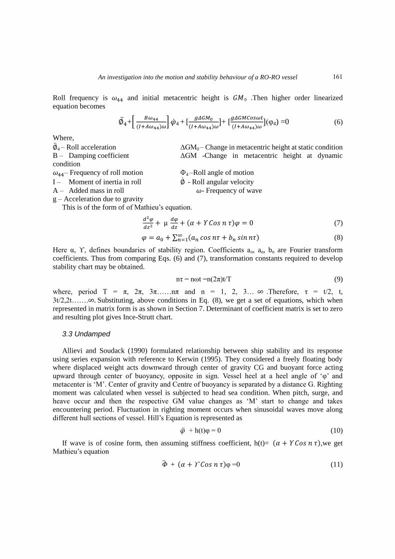
Roll frequency is 𝜔44 and initial metacentric height is 𝐺𝑀0 .Then higher order linearized
equation becomes
∅4 +*
𝐵𝜔44
(𝐼+𝐴𝜔44)𝜔+ ��4 + [
𝑔𝛥𝐺𝑀0
(𝐼+𝐴𝜔44)𝜔]+ [
𝑔𝛥𝐺𝑀𝐶𝑜𝑠𝜔𝑡
(𝐼+𝐴𝜔44)𝜔](φ4) =0 (6)
Where,
∅4 – Roll acceleration ΔGM0 – Change in metacentric height at static condition
B – Damping coefficient ΔGM -Change in metacentric height at dynamic
condition
𝜔44– Frequency of roll motion Փ4 –Roll angle of motion
I – Moment of inertia in roll ∅ - Roll angular velocity
A – Added mass in roll 𝜔- Frequency of wave
g – Acceleration due to gravity
This is of the form of of Mathieu‟s equation.
µ
( 𝐶𝑜𝑠 )𝜑 (7)
𝜑 ∑ ( 𝑜𝑠 𝑠 ) (8)
Here α, ϒ, defines boundaries of stability region. Coefficients ao, an, bn are Fourier transform
coefficients. Thus from comparing Eqs. (6) and (7), transformation constants required to develop
stability chart may be obtained.
nτ = nωt =n(2π)t/T (9)
where, period T = π, 2π, 3π……nπ and n = 1, 2, 3… .Therefore, τ = t/2, t,
3t/2,2t……. Substituting, above conditions in Eq. (8), we get a set of equations, which when
represented in matrix form is as shown in Section 7. Determinant of coefficient matrix is set to zero
and resulting plot gives Ince-Strutt chart.
3.3 Undamped Allievi and Soudack (1990) formulated relationship between ship stability and its response
using series expansion with reference to Kerwin (1995). They considered a freely floating body
where displaced weight acts downward through center of gravity CG and buoyant force acting
upward through center of buoyancy, opposite in sign. Vessel heel at a heel angle of „φ‟ and
metacenter is „M‟. Center of gravity and Centre of buoyancy is separated by a distance G. Righting
moment was calculated when vessel is subjected to head sea condition. When pitch, surge, and
heave occur and then the respective GM value changes as „M‟ start to change and takes
encountering period. Fluctuation in righting moment occurs when sinusoidal waves move along
different hull sections of vessel. Hill‟s Equation is represented as
�� + h(t)φ = 0 (10)
If wave is of cosine form, then assuming stiffness coefficient, h(t)= ( 𝐶𝑜𝑠 ),we get
Mathieu‟s equation
+ ( 𝐶𝑜𝑠 )φ =0 (11)
161
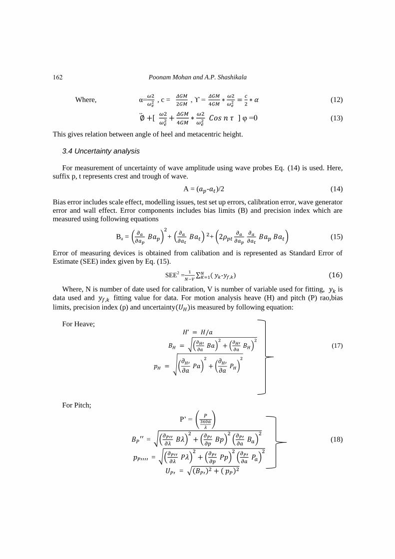
Poonam Mohan and A.P. Shashikala
Where, α=𝜔2
𝜔 , c =
𝛥𝐺𝑀
2𝐺𝑀 , ϒ =
𝛥𝐺𝑀
4𝐺𝑀
𝜔2
𝜔
2 (12)
∅ [ 𝜔2
𝜔
𝛥𝐺𝑀
4𝐺𝑀
𝜔2
𝜔 𝐶𝑜𝑠 ] φ =0 (13)
This gives relation between angle of heel and metacentric height.
3.4 Uncertainty analysis For measurement of uncertainty of wave amplitude using wave probes Eq. (14) is used. Here,
suffix p, t represents crest and trough of wave.
A = ( - 𝑡)/2 (14)
Bias error includes scale effect, modelling issues, test set up errors, calibration error, wave generator
error and wall effect. Error components includes bias limits (B) and precision index which are
measured using following equations
Ba = (
)
2
+ (
𝑡)
2+ ( 𝑡
𝑡) (15)
Error of measuring devices is obtained from calibation and is represented as Standard Error of
Estimate (SEE) index given by Eq. (15).
SEE2 =
∑ (
- ) ( )
Where, N is number of date used for calibration, V is number of variable used for fitting, is
data used and fitting value for data. For motion analysis heave (H) and pitch (P) rao,bias
limits, precision index (p) and uncertainty(𝑈𝐻)is measured by following equation:
For Heave; /
𝐻 √(
)
2
(
𝐻)
2
(17)
𝐻 √( 𝐻
)
2
( 𝐻
𝐻)
2
For Pitch;
P‟ = (
0
)
= √(
)
2 (
)
2(
)
2 (18)
= √(
)
2 (
)
2(
)
2
𝑈 = √( )2 ( )
2
162
An investigation into the motion and stability behaviour of a RO-RO vessel
Similarly, uncertainty in frequency of wave, roll RAO etc.. can be calculated. Overall uncertainity
is given by
𝑈𝐻 = √(𝑈𝐻)2 (
𝑈 )
2
𝑈 = √(𝑈 )2 (
𝑈 )
2
(19)
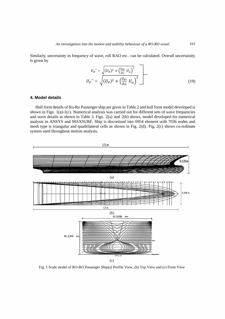
4. Model details
Hull form details of Ro-Ro Passenger ship are given in Table 2 and hull form model developed is
shown in Figs. 1(a)-1(c). Numerical analysis was carried out for different sets of wave frequencies
and wave details as shown in Table 3. Figs. 2(a) and 2(b) shows, model developed for numerical
analysis in ANSYS and MAXSURF. Ship is discretized into 6954 element with 7036 nodes and
mesh type is triangular and quadrilateral cells as shown in Fig. 2(d). Fig. 2(c) shows co-ordinate
system used throughout motion analysis.
(a)
(b)
(c)
Fig. 1 Scale model of RO-RO Passenger Ship(a) Profile View, (b) Top View and (c) Front View
163
Poonam Mohan and A.P. Shashikala
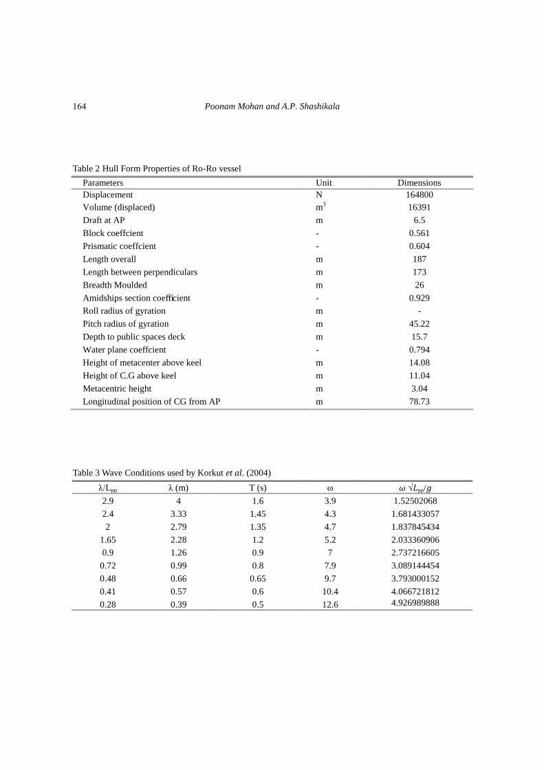
Table 2 Hull Form Properties of Ro-Ro vessel
Parameters Unit Dimensions
Displacement N 164800
Volume (displaced) m3 16391
Draft at AP m 6.5
Block coeffcient - 0.561
Prismatic coeffcient - 0.604
Length overall m 187
Length between perpendiculars m 173
Breadth Moulded m 26
Amidships section coefficient - 0.929
Roll radius of gyration m -
Pitch radius of gyration m 45.22
Depth to public spaces deck m 15.7
Water plane coeffcient - 0.794
Height of metacenter above keel m 14.08
Height of C.G above keel m 11.04
Metacentric height m 3.04
Longitudinal position of CG from AP m 78.73
Table 3 Wave Conditions used by Korkut et al. (2004)
λ/Lpp λ (m) T (s) ω 𝜔 √𝐿pp/𝑔
2.9 4 1.6 3.9 1.52502068
2.4 3.33 1.45 4.3 1.681433057
2 2.79 1.35 4.7 1.837845434
1.65 2.28 1.2 5.2 2.033360906
0.9 1.26 0.9 7 2.737216605
0.72 0.99 0.8 7.9 3.089144454
0.48 0.66 0.65 9.7 3.793000152
0.41 0.57 0.6 10.4 4.066721812
0.28 0.39 0.5 12.6 4.926989888
164
An investigation into the motion and stability behaviour of a RO-RO vessel
(a) (b)
(c) (d)
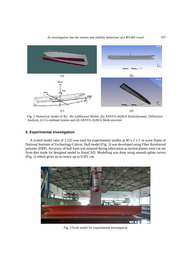
Fig. 2 Numerical model of Ro –Ro (a)Maxsurf Model, (b) ANSYS-AQWA Hydrodynamic Diffraction
Analysis, (c) Co-ordinate system and (d) ANSYS-AQWA Mesh structure
5. Experimental investigation A scaled model ratio of 1:125 was used for experimental studies at 40 x 2 x 2 m wave flume of
National Institute of Technology Calicut. Hull model (Fig. 3) was developed using Fiber Reinforced
polymer (FRP). Accuracy of hull form was ensured during fabrication as section planes were cut out
from dies made for designed model in AutoCAD. Modelling was done using smooth spline curves
(Fig. 1) which gives an accuracy up to 0.001 cm.
Fig. 3 Scale model for experimental investigation
165
Poonam Mohan and A.P. Shashikala
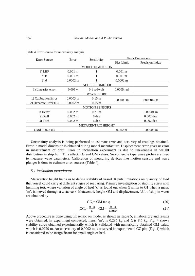
Table 4 Error source for uncertainty analysis
Error Source Error Sensitivity Error Component
Bias Limit Precision Index
MODEL DIMENSION
1) LBP 0.001 m 1 0.001 m
2) B 0.001 m 1 0.001 m
3) d 0.0002 m 1 0.0002 m
ACCELEROMETER
1) Linearity error 0.005 v 0.1 rad/volt 0.0005 rad
WAVE PROBE
1) Calibration Error 0.0003 m 0.15 m 0.00003 m 0.000045 m 2) Dynamic Error (B) 0.0002 m 0.15 m
MOTION SENSORS
1) Heave 0.002 m 0.21 m
0.00001 m
2) Roll 0.002 m 6 deg 0.002 deg
3) Pitch 0.002 m 6 deg 0.002 deg
METACENTRIC HEIGHT
GMd (0.023 m)
0.002 m 0.00005 m
Uncertainty analysis is being performed to estimate error and accuracy of readings obtained.
Error in model dimension is obtained during model manufacture. Displacement error gives us error
in measurement of draft. Error in inclination experiment is due to unevenness in weight
distribution in ship hull. This affect KG and GM values. Servo needle type wave probes are used
to measure wave parameters. Calibration of measuring devices like motion sensors and wave
plunger is done to estimate error sources (Table 4).
5.1 Inclination experiment Metacentric height helps us to define stability of vessel. It puts limitations on quantity of load
that vessel could carry at different stages of sea faring. Primary investigation of stability starts with
Inclining test, where variation of angle of heel „φ‟ is found out when G shifts to G1 when a mass,
„m‟, is moved through a distance x. Metacentric height GM and displacement, „Δ‟, of ship in water
are obtained by
GG1= GM tan φ (20)
GG1=
, GM =
(21)
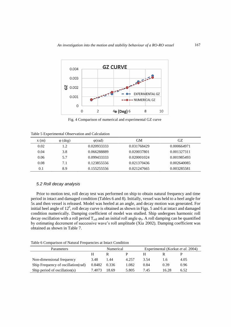
Above procedure is done using tilt sensor on model as shown in Table 5, at laboratory and results
were obtained. In experiment conducted, mass, „m‟, is 0.286 kg and Δ is 8.6 kg. Fig. 4 shows
stability curve obtained experimentally which is validated with numerically obtained GM value,
which is 0.0229 m. An uncertainty of 0.0002 m is observed in experimental GZ plot (Fig. 4) which
is considered to be insignificant for small angle of heel.
166
An investigation into the motion and stability behaviour of a RO-RO vessel
Fig. 4 Comparison of numerical and experimental GZ curve
Table 5 Experimental Observation and Calculation
x (m) φ (deg) φ(rad) GM GZ
0.02 1.2 0.020933333 0.031768429 0.000664971
0.04 3.8 0.066288889 0.020037801 0.001327311
0.06 5.7 0.099433333 0.020001024 0.001985493
0.08 7.1 0.123855556 0.021370436 0.002640085
0.1 8.9 0.155255556 0.021247665 0.003285581
5.2 Roll decay analysis Prior to motion test, roll decay test was performed on ship to obtain natural frequency and time
period in intact and damaged condition (Tables 6 and 8). Initially, vessel was held to a heel angle for
5s and then vessel is released. Model was heeled at an angle, and decay motion was generated. For
initial heel angle of 120, roll decay curve is obtained as shown in Figs. 5 and 6 at intact and damaged
condition numerically. Damping coefficient of model was studied. Ship undergoes harmonic roll
decay oscillation with a roll period Troll and an initial roll angle φ0. A roll damping can be quantified
by estimating decrement of successive wave‟s roll amplitude (Xia 2002). Damping coefficient was
obtained as shown in Table 7.
Table 6 Comparison of Natural Frequencies at Intact Condition
Parameters Numerical Experimental (Korkut et al. 2004)
H R P H R P
Non-dimensional frequency 3.48 1.44 4.257 3.54 1.6 4.05
Ship Frequency of oscillation(rad) 0.8482 0.336 1.082 0.84 0.39 0.96
Ship period of oscillation(s) 7.4073 18.69 5.805 7.45 16.28 6.52
167
Poonam Mohan and A.P. Shashikala
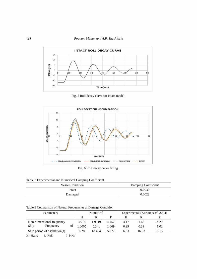
Fig. 5 Roll decay curve for intact model
Fig. 6 Roll decay curve fitting
Table 7 Experimental and Numerical Damping Coefficient
Vessel Condition Damping Coefficient
Intact 0.0030
Damaged 0.0022
Table 8 Comparison of Natural Frequencies at Damage Condition
Parameters Numerical Experimental (Korkut et al. 2004)
H R P H R P
Non-dimensional frequency 3.918 1.9519 4.457 4.17 1.63 4.29
Ship Frequency of
oscillation(rad) 1.0005 0.341 1.069 0.99 0.39 1.02
Ship period of oscillation(s) 6.28 18.424 5.877 6.33 16.03 6.15
H –Heave R- Roll P- Pitch
168
An investigation into the motion and stability behaviour of a RO-RO vessel
Using damping coefficient and period measured in roll decay test curve fitting is done as shown
in Fig. 6. From Eq. (23), damping coefficient δ can be computed depending on roll period Troll and
two consecutive roll angle maxima φi and φi+1 (Molland 2008).
φ(t) φAe-δtcosω0t (22)
log2
+ (23)
Roll decay analysis was performed up-to 70s for which 3 oscillation was completed in 65 s (Fig. 5).
In numerical roll decay analysis, a section of hull is considered to be damaged of size 0.043m to aft
of hull. Opening is located 0.19 m from mid-section of hull. Roll decay under damaged condition is
as shown in Fig. 6. Both in intact and damaged condition, curve show decay in roll amplitudes,
although, after damage, decay of roll amplitude was faster and 3 oscillation was completed in 55s.
Results were validated with that of Korkut et al. (2004). Ro-Ro vessels are designed to operate close
to GM value at damaged condition. Hence damage roll decay response is considered important.
Numerical study on roll decay at intact and damaged condition was done to understand damping
coefficient, which is given in Table 7. Table 6 also shows that natural frequency of vessel in intact
condition is 0.8482 while in damaged condition is 1.0005, which is close.
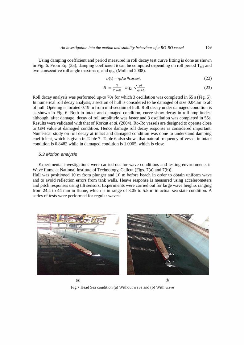
5.3 Motion analysis
Experimental investigations were carried out for wave conditions and testing environments in
Wave flume at National Institute of Technology, Calicut (Figs. 7(a) and 7(b)).
Hull was positioned 10 m from plunger and 10 m before beach in order to obtain uniform wave
and to avoid reflection errors from tank walls. Heave response is measured using accelerometers
and pitch responses using tilt sensors. Experiments were carried out for large wave heights ranging
from 24.4 to 44 mm in flume, which is in range of 3.05 to 5.5 m in actual sea state condition. A
series of tests were performed for regular waves.
(a) (b)
Fig.7 Head Sea condition (a) Without wave and (b) With wave
169
Poonam Mohan and A.P. Shashikala
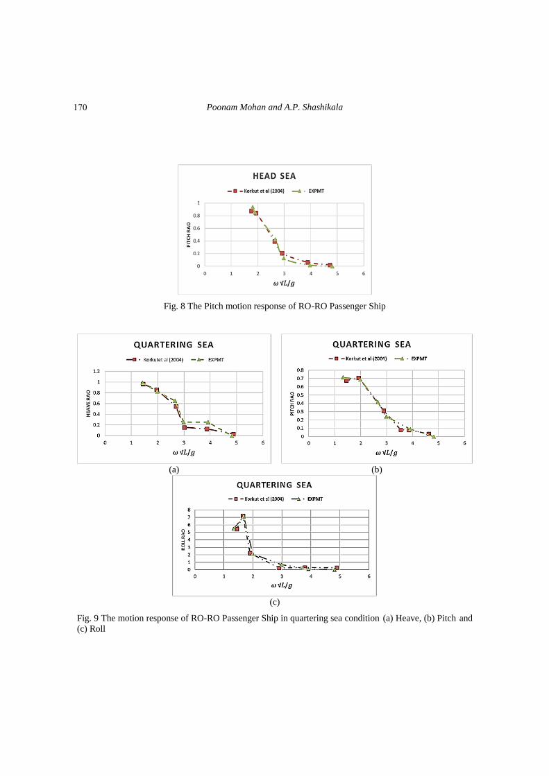
Fig. 8 The Pitch motion response of RO-RO Passenger Ship
(a) (b)
(c)
Fig. 9 The motion response of RO-RO Passenger Ship in quartering sea condition (a) Heave, (b) Pitch and
(c) Roll
170
An investigation into the motion and stability behaviour of a RO-RO vessel
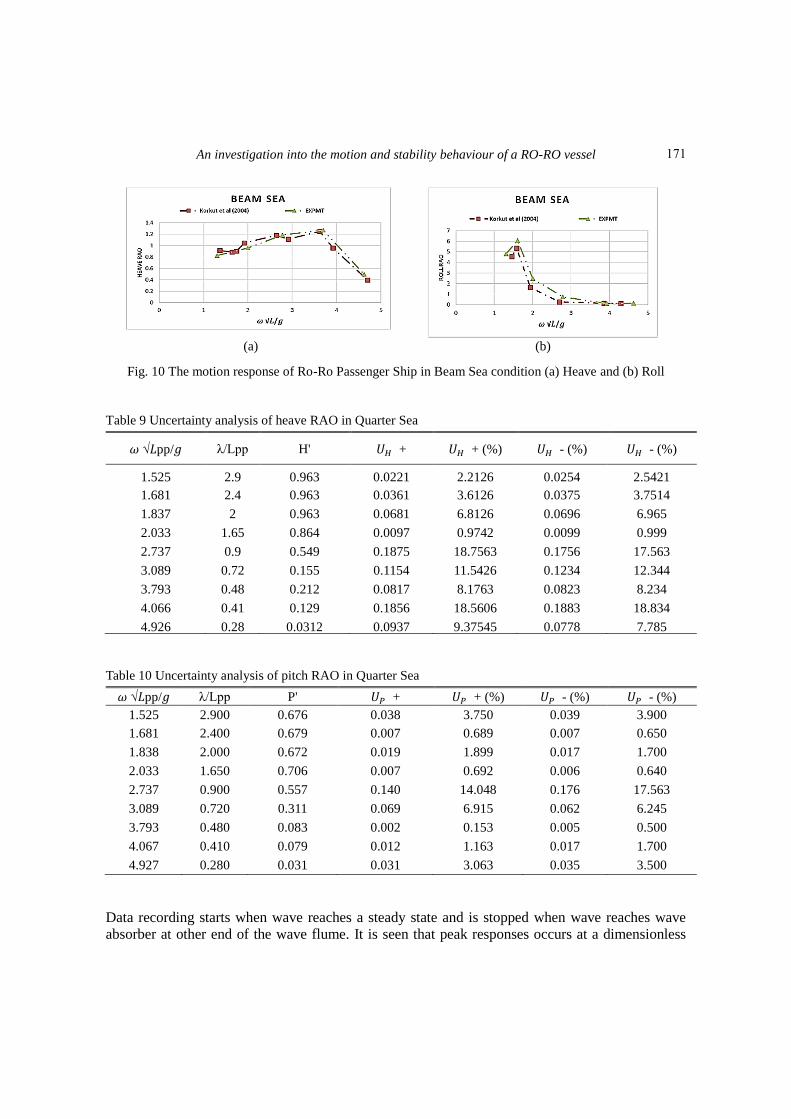
(a) (b)
Fig. 10 The motion response of Ro-Ro Passenger Ship in Beam Sea condition (a) Heave and (b) Roll
Table 9 Uncertainty analysis of heave RAO in Quarter Sea
𝜔 √𝐿pp/𝑔 λ/Lpp H' 𝑈𝐻 + 𝑈𝐻 + (%) 𝑈𝐻 - (%) 𝑈𝐻 - (%)
1.525 2.9 0.963 0.0221 2.2126 0.0254 2.5421
1.681 2.4 0.963 0.0361 3.6126 0.0375 3.7514
1.837 2 0.963 0.0681 6.8126 0.0696 6.965
2.033 1.65 0.864 0.0097 0.9742 0.0099 0.999
2.737 0.9 0.549 0.1875 18.7563 0.1756 17.563
3.089 0.72 0.155 0.1154 11.5426 0.1234 12.344
3.793 0.48 0.212 0.0817 8.1763 0.0823 8.234
4.066 0.41 0.129 0.1856 18.5606 0.1883 18.834
4.926 0.28 0.0312 0.0937 9.37545 0.0778 7.785
Table 10 Uncertainty analysis of pitch RAO in Quarter Sea
𝜔 √𝐿pp/𝑔 λ/Lpp P' 𝑈 + 𝑈 + (%) 𝑈 - (%) 𝑈 - (%)
1.525 2.900 0.676 0.038 3.750 0.039 3.900
1.681 2.400 0.679 0.007 0.689 0.007 0.650
1.838 2.000 0.672 0.019 1.899 0.017 1.700
2.033 1.650 0.706 0.007 0.692 0.006 0.640
2.737 0.900 0.557 0.140 14.048 0.176 17.563
3.089 0.720 0.311 0.069 6.915 0.062 6.245
3.793 0.480 0.083 0.002 0.153 0.005 0.500
4.067 0.410 0.079 0.012 1.163 0.017 1.700
4.927 0.280 0.031 0.031 3.063 0.035 3.500
Data recording starts when wave reaches a steady state and is stopped when wave reaches wave
absorber at other end of the wave flume. It is seen that peak responses occurs at a dimensionless
171
Poonam Mohan and A.P. Shashikala
frequency of 1.5 which corresponds to resonance frequency as shown in Figs. 8-10. These results are
used to validate the model developed.
On performing uncertainty analysis for quarter sea heave and pitch responses, it is found that
nonlinearity occurs at a dimensionless frequency of 2.737 .Uncertainty at this point is maximum of
14.05% in pitch response (Table 10) and 18.75% in case of heave response (Table 9). Similarly
analysis was done for response RAO in head and beam sea conditions. The 95% confidence
interval for pitch and heave RAO‟s was +6% and +8% respectively.
6. Numerical analysis
Numerical analysis is performed by considering a floating body which exhibits 6DOF based on
which motion responses which are calculated in different wave directions (Korkut 2005).
Translational and rotational responses of vessel in 6DOF are as shown in Fig. 2(f). The z-axis is
directed upwards with encountering frequency ωe and wave frequency ω. It was assumed that fluid is
inviscid and incompressible. Strip theory is used which is based on potential flow theory.
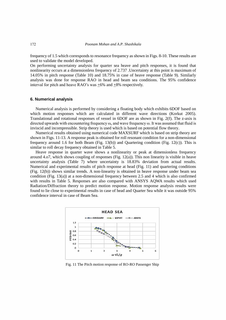
Numerical results obtained using numerical code MAXSURF which is based on strip theory are
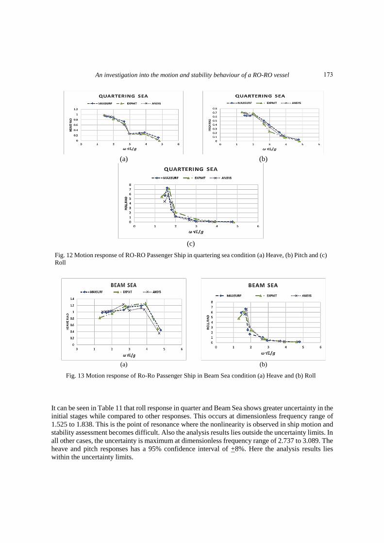
shown in Figs. 11-13. A response peak is obtained for roll resonant condition for a non-dimensional
frequency around 1.6 for both Beam (Fig. 13(b)) and Quartering condition (Fig. 12(c)). This is
similar to roll decay frequency obtained in Table 5.
Heave response in quarter wave shows a nonlinearity or peak at dimensionless frequency
around 4.o7, which shows coupling of responses (Fig. 12(a)). This non linearity is visible in heave
uncertainty analysis (Table 7) where uncertainty is 18.83% deviation from actual results.
Numerical and experimental results of pitch response at head (Fig. 11) and quartering conditions
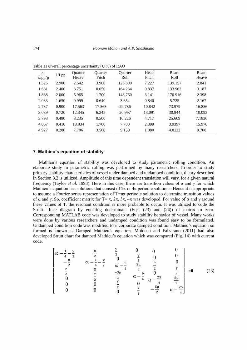
(Fig. 12(b)) shows similar trends. A non-linearity is obtained in heave response under beam sea
condition (Fig. 13(a)) at a non-dimensional frequency between 2.5 and 4 which is also confirmed
with results in Table 5. Responses are also compared with ANSYS AQWA results which used
Radiation/Diffraction theory to predict motion response. Motion response analysis results were
found to lie close to experimental results in case of head and Quarter Sea while it was outside 95%
confidence interval in case of Beam Sea.
Fig. 11 The Pitch motion response of RO-RO Passenger Ship
172
An investigation into the motion and stability behaviour of a RO-RO vessel
(a) (b)
(c)
Fig. 12 Motion response of RO-RO Passenger Ship in quartering sea condition (a) Heave, (b) Pitch and (c)
Roll
(a) (b)
Fig. 13 Motion response of Ro-Ro Passenger Ship in Beam Sea condition (a) Heave and (b) Roll
It can be seen in Table 11 that roll response in quarter and Beam Sea shows greater uncertainty in the
initial stages while compared to other responses. This occurs at dimensionless frequency range of
1.525 to 1.838. This is the point of resonance where the nonlinearity is observed in ship motion and
stability assessment becomes difficult. Also the analysis results lies outside the uncertainty limits. In
all other cases, the uncertainty is maximum at dimensionless frequency range of 2.737 to 3.089. The
heave and pitch responses has a 95% confidence interval of +8%. Here the analysis results lies
within the uncertainty limits.
173
Poonam Mohan and A.P. Shashikala
Table 11 Overall percentage uncertainty (U %) of RAO
𝜔
√𝐿pp/𝑔 λ/Lpp
Quarter
Heave
Quarter
Pitch
Quarter
Roll
Head
Pitch
Beam
Roll
Beam
Heave
1.525 2.900 2.542 3.900 126.800 7.227 139.157 2.841
1.681 2.400 3.751 0.650 164.234 0.837 133.962 3.187
1.838 2.000 6.965 1.700 148.760 3.141 170.916 2.398
2.033 1.650 0.999 0.640 3.654 0.840 5.725 2.167
2.737 0.900 17.563 17.563 29.786 10.842 73.979 16.856
3.089 0.720 12.345 6.245 20.997 13.091 30.944 10.093
3.793 0.480 8.235 0.500 10.226 4.717 25.609 7.1826
4.067 0.410 18.834 1.700 7.700 2.399 3.9397 15.976
4.927 0.280 7.786 3.500 9.150 1.080 4.8122 9.708
7. Mathieu’s equation of stability
Mathieu‟s equation of stability was developed to study parametric rolling condition. An
elaborate study in parametric rolling was performed by many researchers. In-order to study
primary stability characteristics of vessel under damped and undamped condition, theory described
in Section 3.2 is utilized. Amplitude of this time dependent translation will vary, for a given natural
frequency (Taylor et al. 1993). Here in this case, there are transition values of α and γ for which
Mathieu‟s equation has solutions that consist of 2π or 4π periodic solutions. Hence it is appropriate
to assume a Fourier series representation of T=nπ periodic solution to determine transition values
of α and γ. So, coefficient matrix for T= π, 2π, 3π, 4π was developed. For value of α and γ around
these values of T, the resonant condition is more probable to occur. It was utilized to code the
Strutt –Ince diagram by equating determinant (Eqs. (23) and (24)) of matrix to zero.
Corresponding MATLAB code was developed to study stability behavior of vessel. Many works
were done by various researchers and undamped condition was found easy to be formulated.
Undamped condition code was modified to incorporate damped condition. Mathieu‟s equation so
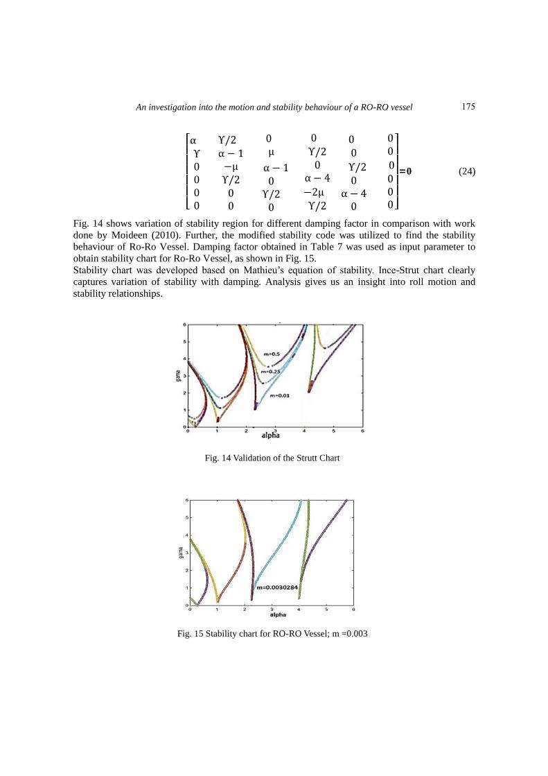
formed is known as Damped Mathieu‟s equation. Moideen and Falzarano (2011) had also
developed Strutt chart for damped Mathieu‟s equation which was compared (Fig. 14) with current
code.
[ ∝ −
4−
𝛾
2
−𝜇
2𝛾
2
𝜇
2
∝ −
4−
𝛾
2
ϒ
2
𝛾
2
∝ −9
4 3μ
2ϒ
2
γ
23μ
2
α −9
4
ϒ
2
ϒ
2
α −25
4
−5μ
2
ϒ
25μ
2
α −25
4 ]
=0 (23)
174
An investigation into the motion and stability behaviour of a RO-RO vessel
[ α ϒ
ϒ/ α − −µϒ/
µ
α − ϒ/
ϒ/
α − 4
− µ ϒ/
ϒ/
α − 4
]
=0 (24)
Fig. 14 shows variation of stability region for different damping factor in comparison with work
done by Moideen (2010). Further, the modified stability code was utilized to find the stability
behaviour of Ro-Ro Vessel. Damping factor obtained in Table 7 was used as input parameter to
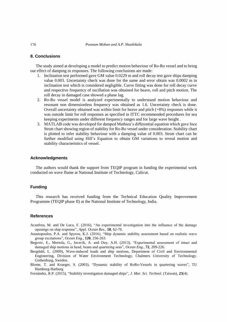
obtain stability chart for Ro-Ro Vessel, as shown in Fig. 15.
Stability chart was developed based on Mathieu‟s equation of stability. Ince-Strut chart clearly
captures variation of stability with damping. Analysis gives us an insight into roll motion and
stability relationships.
Fig. 14 Validation of the Strutt Chart
Fig. 15 Stability chart for RO-RO Vessel; m =0.003
175
Poonam Mohan and A.P. Shashikala
8. Conclusions
The study aimed at developing a model to predict motion behaviour of Ro-Ro vessel and to bring
out effect of damping in responses. The following conclusions are made:
1. Inclination test performed gave GM value 0.0229 m and roll decay test gave ships damping
value 0.003. Uncertainty check was done for the same and error obtain was 0.0002 m in
inclination test which is considered negligible. Curve fitting was done for roll decay curve
and respective frequency of oscillation was obtained for heave, roll and pitch motion. The
roll decay in damaged case showed a phase lag.
2. Ro-Ro vessel model is analyzed experimentally to understand motion behaviour and
resonant non dimensionless frequency was obtained as 1.6. Uncertainty check is done.
Overall uncertainty obtained was within limit for heave and pitch (+8%) responses while it
was outside limit for roll responses as specified in ITTC recommended procedures for sea
keeping experiments under different frequency ranges and for large wave height .
3. MATLAB code was developed for damped Mathieu‟s differential equation which gave Ince
Strutt chart showing region of stability for Ro-Ro vessel under consideration. Stability chart
is plotted to infer stability behaviour with a damping value of 0.003. Strutt chart can be
further modified using Hill‟s Equation to obtain GM variations to reveal motion and
stability characteristics of vessel.
Acknowledgments The authors would thank the support from TEQIP program in funding the experimental work
conducted on wave flume at National Institute of Technology, Calicut.
Funding This research has received funding from the Technical Education Quality Improvement
Programme (TEQIP phase II) at the National Institute of Technology, India.
References
Acanfora, M. and De Luca, F. (2016), “An experimental investigation into the influence of the damage
openings on ship response”, Appl. Ocean Res., 58, 62-70.
Anastopoulos, P.A. and Spyrou, K.J. (2016), “Ship dynamic stability assessment based on realistic wave
group excitations”, Ocean Eng., 120, 256-263.
Begovic, E., Mortola, G., Incecik, A. and Day, A.H. (2013), “Experimental assessment of intact and
damaged ship motions in head, beam and quartering seas”, Ocean Eng., 72, 209-226.
Bergdahl, L. (2009), Wave-induced loads and ship motions, Department of Civil and Environmental
Engineering, Division of Water Environment Technology, Chalmers University of Technology.
Gothenburg, Sweden.
Blome, T. and Krueger, S. (2003), “Dynamic stability of RoRo-Vessels in quartering waves”, TU
Hamburg-Harburg
Fernández, R.P. (2015), “Stability investigation damaged ships”, J. Mar. Sci. Technol. (Taiwan), 23(4).
176
An investigation into the motion and stability behaviour of a RO-RO vessel
Francescutto, A. (2015), “Intact stability criteria of ships - Past, present and future”, Ocean Eng., 120,
312-317.
Hanzu-Pazara, R., Arsenie, P., Duse, A. and Varsami, C. (2016), “Study of VLCC tanker ship damage
stability during off-shore operation”, Proceedings of the IOP Conference Series: Materials Science and
Engineering , 145. http://doi.org/10.1088/1757-899X/145/8/082020
Hsiung, C.C. and Huang, Z.J. (1991), “Comparision of the strip theory and the panel method in computing
ship motion with forward speed”, Proceedings of the Symposium on Selected Topics of Marine
Hydrodynamics, St. John's, Nfld.
Ibrahim, R.A. and Grace, I.M. (2010), “Modeling of ship roll dynamics and its coupling with heave and
pitch”, Math. Problem.Eng., Article ID 934714.
Insperger, T. and St p n, G. (2003), “Stability of the damped mathieu equation with time delay”, J. Dyn.
Syst. Meas. Control, 125(2), 166.
Kerwin, J.E. (1995), “Notes on rolling in longitudinal waves”, Int. Shipbuild. Progress, 2(16), 597-614.
Knapp, G.F. and Anderson, S.L. (1995), U.S. Patent No. 5,474,454. Washington, DC: U.S. Patent and
Trademark Office.
Korkut, E, Atlar, M. and Incecik, A. (2004), “An experimental study of motion behaviour with an intact and
damaged Ro-Ro ship model”, Ocean Eng., 31(3-4), 483-512.
Korkut, E., Atlar, M. and Incecik, A. (2005), “An experimental study of global loads acting on an intact and
damaged Ro-Ro ship model”, Ocean Eng., 32(11-12), 1370-1403.
Maxsurf Motions Program and User Manual (2015), Bentley Systems.
Moideen, H. (2010), “Prediction of parametric roll of ships in regular and irregular sea”, December, 148.
Moideen, H. and Falzarano, J.M. (2011), “A critical assessment of ship parametric roll analysis”,
Proceedings of the 11th International Ship Stability Workshop.
Molland, A.F. (2008), The Maritime Engineering Reference Book, Butterworth Heinemann.
Ribeiro, J, Silva, E, Santos, T.A. and Guedes Soares, C (2010), “On the parametric excitation of a container
vessel”, Int. Shipbuild. Program., 52, 29-56.
Taylan, M. (2004), “Effect of forward speed on ship rolling and stability”, Math. Comput. Appl., 9(2),
133-145.
Taylor, R.E., Brown, D.T. and Patel, M.H. (1983), “Barge motions in random seas - a comparison of theory
and experiment”, J. Fluid Mech., 129, 385-407.
Xia, J. and Fan, S. (2002), Simulation of ship motions - coupled heave, pitch and roll. centre for marine
science and technology, Technical Report no. 35. WA: UWA.
Zakaria, N.M.G. (2007), “Effect of ship size, forward speed and wave direction on relative wave height of
container ships in rough seas”, IEM J., 70(3), 21- 34.
PL
177