Embed Size (px)
Citation preview
IEEE TRANSACTIONS ON EDUCATION, VOL. 45, NO. 3, AUGUST 2002 289
An Introductory Digital Design Course Using aLow-Cost Autonomous Robot
Kimberly E. Newman, Member, IEEE, James O. Hamblen, Senior Member, IEEE, andTyson S. Hall, Student Member, IEEE
Abstract—This paper describes a new digital design laboratorydeveloped for undergraduate students in this electrical andcomputer engineering curriculum. A top-down rapid prototypingapproach with commercial computer-aided design tools andfield-programmable logic devices (FPLDs) is used for laboratoryprojects. Students begin with traditional transistor–transistorlogic-based projects containing a few gates and progress to de-signing a simple 16-bit computer, using very high-speed integratedcircuits hardware description language (VHDL) synthesis toolsand an FPLD. To help motivate students, the simple computerdesign is programmed to control a small autonomous robotwith two servo drive motors and several sensors. The laboratoryconcludes with a team-based design project using the robot.
Index Terms—Autonomous robot, digital design, field-pro-grammable logic device (FPLD), sequential logic, very high-speedintegrated circuits hardware description language (VHDL)synthesis.
I. INTRODUCTION
T HE NATURE and background of undergraduate studentsentering electrical and computer engineering (ECE) pro-
grams have changed significantly in recent decades. Traditionalpedagogical methods of teaching theory before looking at appli-cations do not adequately address the needs of today’s students[1], [2]. Without previous, relevant experience, students are notmotivated to learn the material in the fundamental engineeringcourses that traditionally fill the students’ first several years ofcourse work [1]. In an effort to appeal to this new generationof engineering students, promote higher retention rates, and in-crease motivation in undergraduate students, the faculty at theGeorgia Institute of Technology (Georgia Tech) have redesignedthe computer engineering curricula to follow a more top-downapproach [2].
Traditionally, transistor–transistor logic (TTL) proto-board-based projects have formed the backbone of digitaldesign laboratories. Because of the time-intensive nature ofdesigning with this technology, projects in an introductorylaboratory are limited to a handful of gates. This limitationis unacceptable when trying to introduce students to moreinteresting real-world applications. Alternatively, field-pro-grammable logic devices (FPLDs), which include bothfield-programmable gate arrays and complex programmablelogic devices, offer a design platform that allows students to
Manuscript received August 14, 2000; revised February 21, 2002.K. E. Newman is with the School of Engineering and Computer Science,
University of Denver, Denver, CO 80208 USA.J. O. Hamblen and T. S. Hall are with the School of Electrical and Computer
Engineering, Georgia Institute of Technology, Atlanta, GA 30332 USA.Publisher Item Identifier S 0018-9359(02)05044-6.
Fig. 1. Altera’s UP 1 board contains two FPLDs. All projects discussed in thispaper use the larger FLEX 10K20 FPLD located on the right-hand side of thisboard. This FPLD contains the equivalent of�20 000 logic gates.
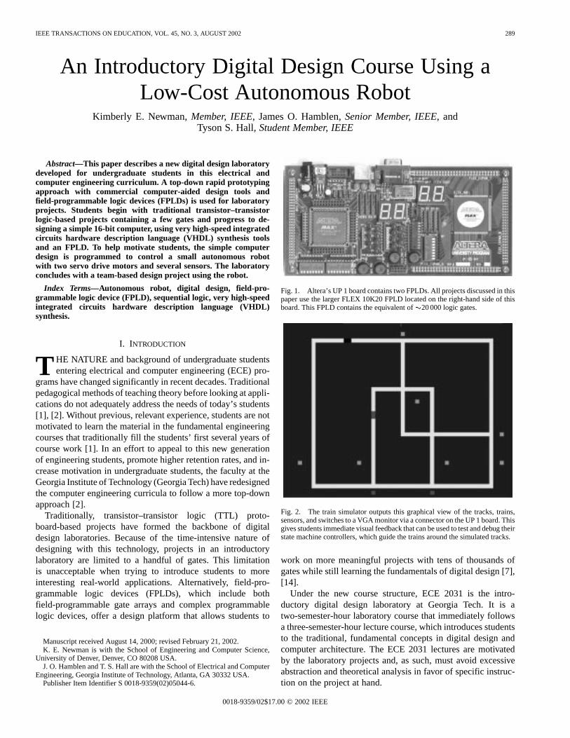
Fig. 2. The train simulator outputs this graphical view of the tracks, trains,sensors, and switches to a VGA monitor via a connector on the UP 1 board. Thisgives students immediate visual feedback that can be used to test and debug theirstate machine controllers, which guide the trains around the simulated tracks.
work on more meaningful projects with tens of thousands ofgates while still learning the fundamentals of digital design [7],[14].
Under the new course structure, ECE 2031 is the intro-ductory digital design laboratory at Georgia Tech. It is atwo-semester-hour laboratory course that immediately followsa three-semester-hour lecture course, which introduces studentsto the traditional, fundamental concepts in digital design andcomputer architecture. The ECE 2031 lectures are motivatedby the laboratory projects and, as such, must avoid excessiveabstraction and theoretical analysis in favor of specific instruc-tion on the project at hand.
0018-9359/02$17.00 © 2002 IEEE
290 IEEE TRANSACTIONS ON EDUCATION, VOL. 45, NO. 3, AUGUST 2002
II. L ABORATORY LOGISTICS
The students’ workload is divided into three phases: prelab,in-lab, and postlab. Before each laboratory session, studentsattend a one-hour lecture given by a faculty member. They arealso required to complete “prelab exercises” before coming tothe laboratory. These exercises vary from week to week, butthey are designed to take no more than two hours per week andtypically include reading from the textbook, working throughonline tutorials, and/or completing an initial circuit design usingthe freely distributed student edition of Altera’s MAX+PLUS IIsoftware. The laboratory session lasts three hours each week andis supervised by graduate and undergraduate teaching assistantssuch that there is, at worst, a 6 : 1 ratio of students to teachingassistants. Undergraduate teaching assistants also staff thelaboratory during limited hours in the evenings and on weekendsfor the few students who fail to complete the laboratoryassignment during their regular session. After completing eachassignment, students must write a laboratory report summarizingtheir work and results. The length, format, and formality ofthese reports vary throughout the semester to give students theopportunity of writing different types of reports. On average,students are expected to spend six hours working on eachlaboratory assignment, including lecture, prelab exercises, andin-lab time.
III. D IGITAL DESIGN USING CAD TOOLS AND FPGAS
The tradeoffs between using commercial and special-purposeeducational tools in a laboratory setting are well debated inengineering educational literature [3]. To provide students withthe tools to be productive and innovative in today’s rapidlyevolving market, academia must keep pace with industry. Byusing commercial products in a controlled/limited laboratoryenvironment, students are trained to use the tools that willmake them immediately productive in industry. They are alsoprovided with standard training in digital design theories andpractices that will equip them to challenge current technologieswith new discoveries [12]. In 1995, students at Georgia Techbegan using commercial computer-aided design (CAD) toolsin senior design classes to design, simulate, and synthesize re-duced instruction set computer processor cores [4], [15]. Sincethen, similar CAD tools have been successfully introduced intojunior-level computer architecture courses, and now into thesophomore-level digital design laboratory as well.
In recent years, FPLD vendors, such as Altera and Xilinx,have offered student versions of CAD tools for a nominal feeor for free. These vendors also offer reasonably sized FPLDs(currently 4000 to 70 000 equivalent gates) integrated ontostudent development boards. (Several commercial offerings arehighlighted in [2].) In particular, Altera’s UP 1 board, shownin Fig. 1, contains two independent FPLDs, pushbuttons, DIPswitches, light-emitting diodes (LEDs), a 15-pin high-densityD-Sub connector for attaching a VGA monitor, a PS/2 con-nector, and external I/O headers. The Altera UP 1 board issufficient for both the introductory digital design laboratoryand the senior design laboratory (although the senior designlaboratory uses larger FPLDs on the new UP1-x board).
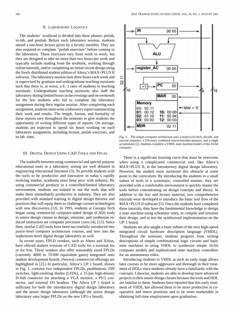
Fig. 3. The simple computer architecture uses a multicycle fetch, decode, andexecute sequence, a 256-entry combined instruction/data memory, and a singleaccumulator [2]. Students complete a VHDL state machine model of this 16-bitcomputer.
There is a significant learning curve that must be overcomewhen using a complicated commercial tool, like Altera’sMAX+PLUS II, in the introductory digital design laboratory.However, the student must surmount this obstacle at somepoint in the curriculum. By introducing the students to a smallsubset of tools in a systematic, controlled manner, they areprovided with a comfortable environment to quickly master thetools before concentrating on design concepts and theory. Inaddition to the text and lecture material, two comprehensivetutorials were developed to introduce the basic tool flow of theMAX+PLUS II software [5]. Once the students have completedthese tutorials, they have the fundamental knowledge to designa state machine using schematic entry, to compile and simulatetheir design, and to test the synthesized implementation on theUP 1 board.
Students are also taught a basic subset of the very high-speedintegrated circuit hardware description language (VHDL).Throughout the semester, students progress from writingdescriptions of simple combinational logic circuits and basicstate machines to using VHDL to synthesize simple 16-bitcomputer models and sophisticated state machine controllersfor an autonomous robot.
Introducing students to VHDL at such an early stage allowslater courses to be more aggressive and thorough in their treat-ment of HDLs since students already have a familiarity with theconcepts. Likewise, students are able to develop more advancedprojects in their senior design classes because the tools and HDLare familiar to them. Students have reported that this early treat-ment of VHDL has allowed them to be more productive in co-operative and intern positions and to be more marketable inobtaining full-time employment upon graduation.
NEWMAN et al.: INTRODUCTORY DIGITAL DESIGN COURSE 291
Fig. 4. A sample memory initialization file that contains instructions and data for testing the basic operations of the simple computer.
Fig. 5. The waveform output from the MAX+PLUS II simulator when the memory is initialized with the MIF file shown in Fig. 4.
IV. L ABORATORY PROJECTS
A. Traditional Protoboard Approach
While adopting top-down pedagogy for the overall cur-riculum, the authors did not want to overlook the fundamentalconcepts within ECE. During the first quarter of the semester,students are introduced to TTL protoboard-based design using7400-series TTL logic integrated circuits (ICs). These earlylaboratory assignments are designed to introduce basic logicgates, counters, decoders, multiplexers, classic state machinedesign, and more. The laboratory assignments in the secondquarter of the semester center on instrumentation and circuitcharacteristics. Students become familiar with digital oscillo-scopes and logic analyzers and learn how to measure circuitcharacteristics, such as rise/fall time, propagation delay, andduty cycle.
B. State Machines
The treatment of state machines provides the transition be-tween protoboard-based design and FPLD-based design. Ini-tially, students use the schematic entry tool in MAX+PLUS II todesign a discrete implementation for the provided state machine.After simulating their design to verify its accuracy, they build iton a protoboard using TTL logic ICs. Finally, they design thesame state machine in VHDL and simulate its operation. Sim-ulation waveforms are compared for the two implementationsand with the original state diagram to verify the correctness ofeach implementation. After being introduced to VHDL in thismanner, students can easily make direct comparisons betweenthese two design methodologies.
At this point in the semester, the transition from proto-board-based design to FPLD-based design is completed byrequiring students to implement a more complicated state
292 IEEE TRANSACTIONS ON EDUCATION, VOL. 45, NO. 3, AUGUST 2002
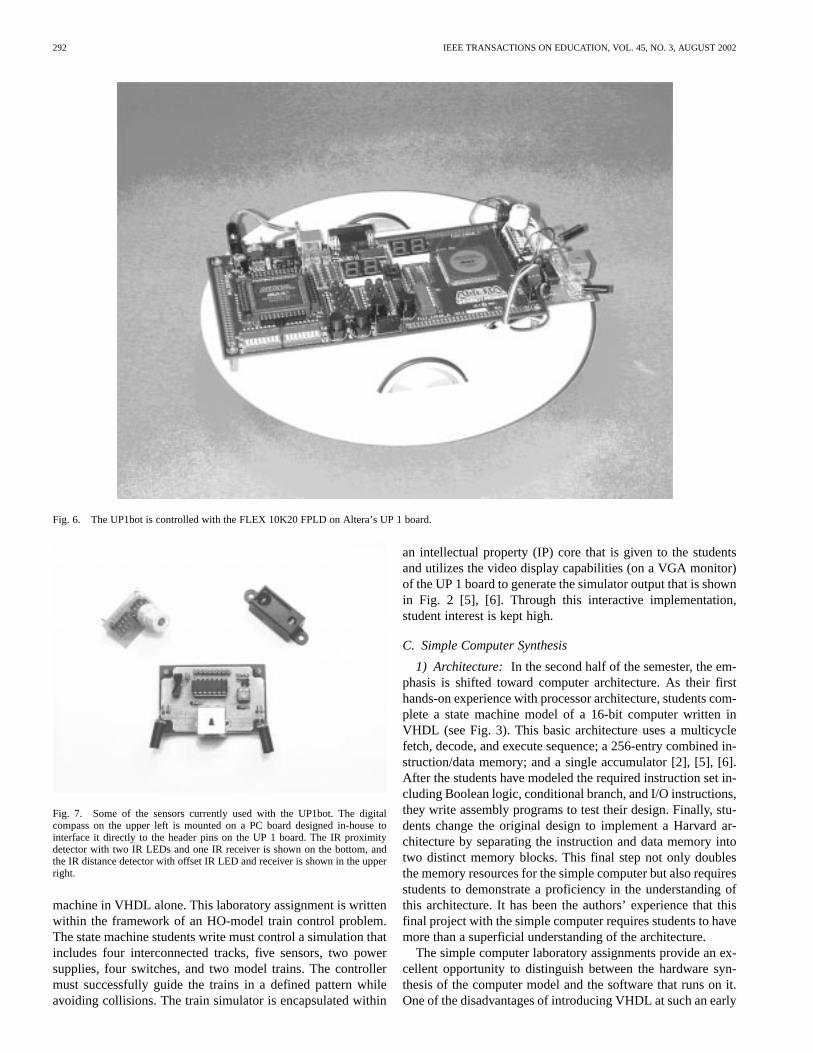
Fig. 6. The UP1bot is controlled with the FLEX 10K20 FPLD on Altera’s UP 1 board.
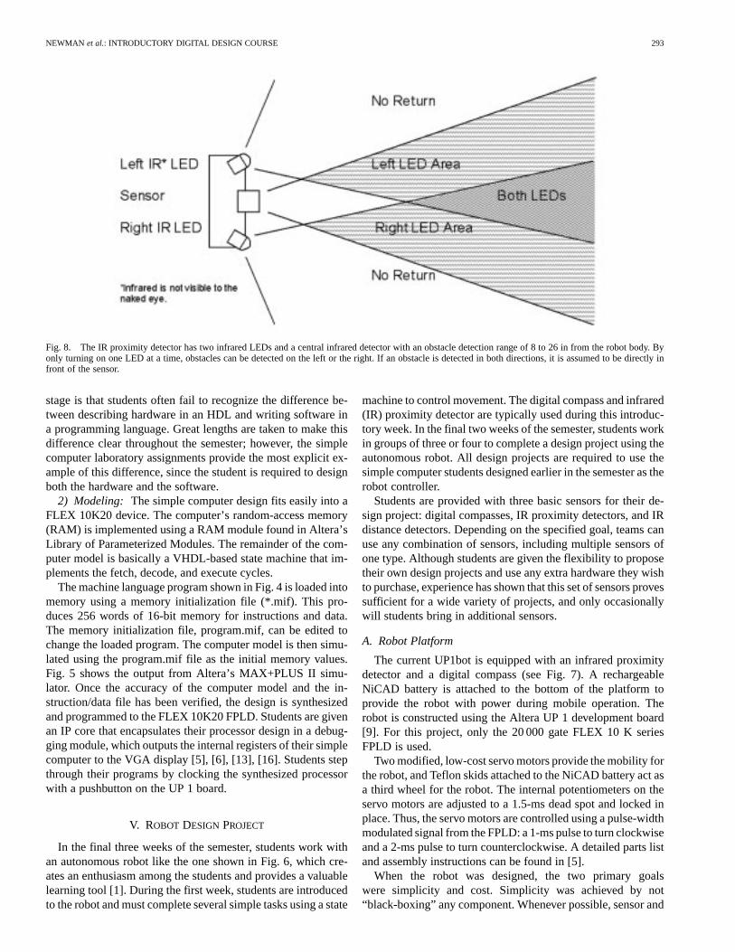
Fig. 7. Some of the sensors currently used with the UP1bot. The digitalcompass on the upper left is mounted on a PC board designed in-house tointerface it directly to the header pins on the UP 1 board. The IR proximitydetector with two IR LEDs and one IR receiver is shown on the bottom, andthe IR distance detector with offset IR LED and receiver is shown in the upperright.
machine in VHDL alone. This laboratory assignment is writtenwithin the framework of an HO-model train control problem.The state machine students write must control a simulation thatincludes four interconnected tracks, five sensors, two powersupplies, four switches, and two model trains. The controllermust successfully guide the trains in a defined pattern whileavoiding collisions. The train simulator is encapsulated within
an intellectual property (IP) core that is given to the studentsand utilizes the video display capabilities (on a VGA monitor)of the UP 1 board to generate the simulator output that is shownin Fig. 2 [5], [6]. Through this interactive implementation,student interest is kept high.
C. Simple Computer Synthesis
1) Architecture: In the second half of the semester, the em-phasis is shifted toward computer architecture. As their firsthands-on experience with processor architecture, students com-plete a state machine model of a 16-bit computer written inVHDL (see Fig. 3). This basic architecture uses a multicyclefetch, decode, and execute sequence; a 256-entry combined in-struction/data memory; and a single accumulator [2], [5], [6].After the students have modeled the required instruction set in-cluding Boolean logic, conditional branch, and I/O instructions,they write assembly programs to test their design. Finally, stu-dents change the original design to implement a Harvard ar-chitecture by separating the instruction and data memory intotwo distinct memory blocks. This final step not only doublesthe memory resources for the simple computer but also requiresstudents to demonstrate a proficiency in the understanding ofthis architecture. It has been the authors’ experience that thisfinal project with the simple computer requires students to havemore than a superficial understanding of the architecture.
The simple computer laboratory assignments provide an ex-cellent opportunity to distinguish between the hardware syn-thesis of the computer model and the software that runs on it.One of the disadvantages of introducing VHDL at such an early
NEWMAN et al.: INTRODUCTORY DIGITAL DESIGN COURSE 293
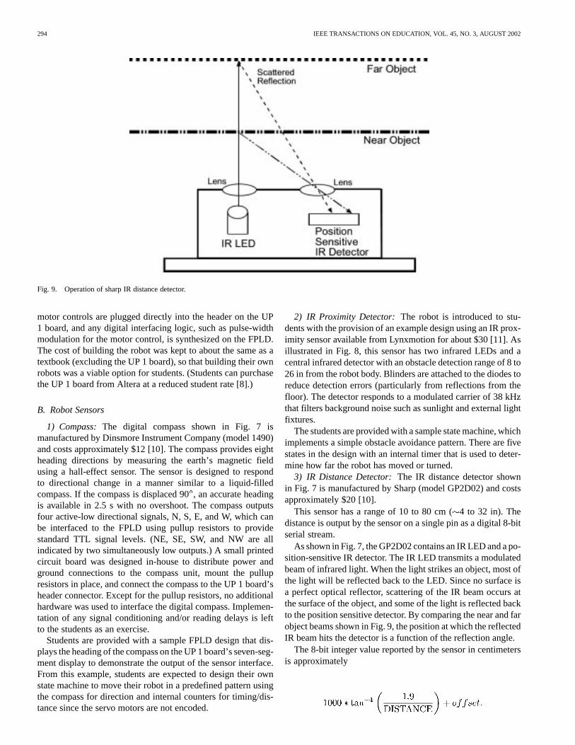
Fig. 8. The IR proximity detector has two infrared LEDs and a central infrared detector with an obstacle detection range of 8 to 26 in from the robot body.Byonly turning on one LED at a time, obstacles can be detected on the left or the right. If an obstacle is detected in both directions, it is assumed to be directly infront of the sensor.
stage is that students often fail to recognize the difference be-tween describing hardware in an HDL and writing software ina programming language. Great lengths are taken to make thisdifference clear throughout the semester; however, the simplecomputer laboratory assignments provide the most explicit ex-ample of this difference, since the student is required to designboth the hardware and the software.
2) Modeling: The simple computer design fits easily into aFLEX 10K20 device. The computer’s random-access memory(RAM) is implemented using a RAM module found in Altera’sLibrary of Parameterized Modules. The remainder of the com-puter model is basically a VHDL-based state machine that im-plements the fetch, decode, and execute cycles.
The machine language program shown in Fig. 4 is loaded intomemory using a memory initialization file (*.mif). This pro-duces 256 words of 16-bit memory for instructions and data.The memory initialization file, program.mif, can be edited tochange the loaded program. The computer model is then simu-lated using the program.mif file as the initial memory values.Fig. 5 shows the output from Altera’s MAX+PLUS II simu-lator. Once the accuracy of the computer model and the in-struction/data file has been verified, the design is synthesizedand programmed to the FLEX 10K20 FPLD. Students are givenan IP core that encapsulates their processor design in a debug-ging module, which outputs the internal registers of their simplecomputer to the VGA display [5], [6], [13], [16]. Students stepthrough their programs by clocking the synthesized processorwith a pushbutton on the UP 1 board.
V. ROBOT DESIGN PROJECT
In the final three weeks of the semester, students work withan autonomous robot like the one shown in Fig. 6, which cre-ates an enthusiasm among the students and provides a valuablelearning tool [1]. During the first week, students are introducedto the robot and must complete several simple tasks using a state
machine to control movement. The digital compass and infrared(IR) proximity detector are typically used during this introduc-tory week. In the final two weeks of the semester, students workin groups of three or four to complete a design project using theautonomous robot. All design projects are required to use thesimple computer students designed earlier in the semester as therobot controller.
Students are provided with three basic sensors for their de-sign project: digital compasses, IR proximity detectors, and IRdistance detectors. Depending on the specified goal, teams canuse any combination of sensors, including multiple sensors ofone type. Although students are given the flexibility to proposetheir own design projects and use any extra hardware they wishto purchase, experience has shown that this set of sensors provessufficient for a wide variety of projects, and only occasionallywill students bring in additional sensors.
A. Robot Platform
The current UP1bot is equipped with an infrared proximitydetector and a digital compass (see Fig. 7). A rechargeableNiCAD battery is attached to the bottom of the platform toprovide the robot with power during mobile operation. Therobot is constructed using the Altera UP 1 development board[9]. For this project, only the 20 000 gate FLEX 10 K seriesFPLD is used.
Two modified, low-cost servo motors provide the mobility forthe robot, and Teflon skids attached to the NiCAD battery act asa third wheel for the robot. The internal potentiometers on theservo motors are adjusted to a 1.5-ms dead spot and locked inplace. Thus, the servo motors are controlled using a pulse-widthmodulated signal from the FPLD: a 1-ms pulse to turn clockwiseand a 2-ms pulse to turn counterclockwise. A detailed parts listand assembly instructions can be found in [5].
When the robot was designed, the two primary goalswere simplicity and cost. Simplicity was achieved by not“black-boxing” any component. Whenever possible, sensor and
294 IEEE TRANSACTIONS ON EDUCATION, VOL. 45, NO. 3, AUGUST 2002
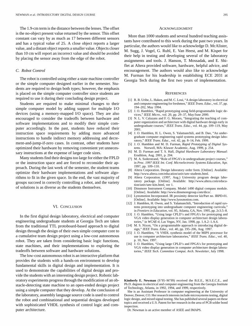
Fig. 9. Operation of sharp IR distance detector.
motor controls are plugged directly into the header on the UP1 board, and any digital interfacing logic, such as pulse-widthmodulation for the motor control, is synthesized on the FPLD.The cost of building the robot was kept to about the same as atextbook (excluding the UP 1 board), so that building their ownrobots was a viable option for students. (Students can purchasethe UP 1 board from Altera at a reduced student rate [8].)
B. Robot Sensors
1) Compass:The digital compass shown in Fig. 7 ismanufactured by Dinsmore Instrument Company (model 1490)and costs approximately $12 [10]. The compass provides eightheading directions by measuring the earth’s magnetic fieldusing a hall-effect sensor. The sensor is designed to respondto directional change in a manner similar to a liquid-filledcompass. If the compass is displaced 90, an accurate headingis available in 2.5 s with no overshoot. The compass outputsfour active-low directional signals, N, S, E, and W, which canbe interfaced to the FPLD using pullup resistors to providestandard TTL signal levels. (NE, SE, SW, and NW are allindicated by two simultaneously low outputs.) A small printedcircuit board was designed in-house to distribute power andground connections to the compass unit, mount the pullupresistors in place, and connect the compass to the UP 1 board’sheader connector. Except for the pullup resistors, no additionalhardware was used to interface the digital compass. Implemen-tation of any signal conditioning and/or reading delays is leftto the students as an exercise.
Students are provided with a sample FPLD design that dis-plays the heading of the compass on the UP 1 board’s seven-seg-ment display to demonstrate the output of the sensor interface.From this example, students are expected to design their ownstate machine to move their robot in a predefined pattern usingthe compass for direction and internal counters for timing/dis-tance since the servo motors are not encoded.
2) IR Proximity Detector:The robot is introduced to stu-dents with the provision of an example design using an IR prox-imity sensor available from Lynxmotion for about $30 [11]. Asillustrated in Fig. 8, this sensor has two infrared LEDs and acentral infrared detector with an obstacle detection range of 8 to26 in from the robot body. Blinders are attached to the diodes toreduce detection errors (particularly from reflections from thefloor). The detector responds to a modulated carrier of 38 kHzthat filters background noise such as sunlight and external lightfixtures.
The students are provided with a sample state machine, whichimplements a simple obstacle avoidance pattern. There are fivestates in the design with an internal timer that is used to deter-mine how far the robot has moved or turned.
3) IR Distance Detector:The IR distance detector shownin Fig. 7 is manufactured by Sharp (model GP2D02) and costsapproximately $20 [10].
This sensor has a range of 10 to 80 cm (4 to 32 in). Thedistance is output by the sensor on a single pin as a digital 8-bitserial stream.
As shown in Fig. 7, the GP2D02 contains an IR LED and a po-sition-sensitive IR detector. The IR LED transmits a modulatedbeam of infrared light. When the light strikes an object, most ofthe light will be reflected back to the LED. Since no surface isa perfect optical reflector, scattering of the IR beam occurs atthe surface of the object, and some of the light is reflected backto the position sensitive detector. By comparing the near and farobject beams shown in Fig. 9, the position at which the reflectedIR beam hits the detector is a function of the reflection angle.
The 8-bit integer value reported by the sensor in centimetersis approximately
NEWMAN et al.: INTRODUCTORY DIGITAL DESIGN COURSE 295
The 1.9-cm term is the distance between the lenses. The offsetis the no-object present value returned by the sensor. This offsetconstant can vary by as much as 17 between different sensorsand has a typical value of 25. A close object reports a largervalue, and a distant object reports a smaller value. Objects closerthan 10 cm will report an incorrect value and should be avoidedby placing the sensor away from the edge of the robot.
C. Robot Control
The robot is controlled using either a state machine controlleror the simple computer designed earlier in the semester. Stu-dents are required to design both types; however, the emphasisis placed on the simple computer controller since students arerequired to use it during their concluding design project.
Students are required to make minimal changes to theirsimple computer model by adding support for multiple I/Odevices (using a memory-mapped I/O space). They are alsoencouraged to consider the tradeoffs between hardware andsoftware implementations and to modify their simple com-puter accordingly. In the past, students have reduced theirinstruction space requirements by adding more advancedinstructions to handle indirect memory addressing and decre-ment-and-jump-if-zero cases. In contrast, other students haveoptimized their hardware by removing convenient yet unneces-sary instructions at the expense of larger code sizes.
Many students find their designs too large for either the FPLDor the instruction space and are forced to reconsider their ap-proach. During the last week of the semester, the student teamsoptimize their hardware implementations and software algo-rithms to fit in the given space. In the end, the vast majority ofgroups succeed in correctly controlling a robot, and the varietyof solutions is as diverse as the students themselves.
VI. CONCLUSION
In the first digital design laboratory, electrical and computerengineering undergraduate students at Georgia Tech are takenfrom the traditional TTL protoboard-based approach to digitaldesign through the design of their own simple computer core toa cumulative team design project using a low-cost autonomousrobot. They are taken from considering basic logic functions,state machines, and their implementations to exploring thetradeoffs between software and hardware solutions.
The low-cost autonomous robot is an interactive platform thatprovides the students with a hands-on environment to developfundamental skills in digital design and implementation. It isused to demonstrate the capabilities of digital design and pro-vide the students with an interesting design project. Robotic lab-oratory experiments progress through the modification of an ob-stacle-detecting state machine to an open-ended design projectusing a simple computer that they develop. At the conclusion ofthe laboratory, assembly language source code is used to controlthe robot and combinational and sequential designs developedwith sophisticated VHDL synthesis of control logic and com-puter architecture.
ACKNOWLEDGMENT
More than 1000 students and several hundred teaching assis-tants have contributed to this work during the past two years. Inparticular, the authors would like to acknowledge D. McAlister,M. Sugg, J. Vogel, G. Ruhl, E. Van Heest, and M. Kispet fortheir help in testing and developing several of the laboratoryassignments and tools. J. Hanson, T. Mossadak, and E. Shi-flet at Altera provided software, hardware, helpful advice, andencouragement. The authors would also like to acknowledgeM. Furman for his leadership in establishing ECE 2031 atGeorgia Tech during the first two years of implementation.
REFERENCES
[1] R. B. Uribe, L. Haken, and M. C. Loui, “A design laboratory in electricaland computer engineering for freshmen,”IEEE Trans. Educ., vol. 37, pp.194–202, May 1994.
[2] J. O. Hamblen, “Rapid prototyping using field-programmable logic de-vices,” IEEE Micro., vol. 20, pp. 29–37, May/June 2000.
[3] N. L. V. Calazans and F. G. Moraes, “Integrating the teaching of com-puter organization and architecture with digital hardware design early inundergraduate courses,”IEEE Trans. Educ., vol. 44, pp. 109–119, May2001.
[4] J. O. Hamblen, H. L. Owen, S. Yalamanchili, and B. Dao, “An under-graduate computer engineering rapid systems prototyping design labo-ratory,” IEEE Trans. Educ., vol. 42, pp. 8–14, Feb. 1999.
[5] J. O. Hamblen and M. D. Furman,Rapid Prototyping of Digital Sys-tems. Norwell, MA: Kluwer Academic, Aug. 1999, p. 254.
[6] M. D. Furman and T. S. Hall,Digital Hardware Laboratory Manual:Erudition, Aug. 2001, p. 204.
[7] M. A. Soderstrand, “Role of FPGA’s in undergraduate project courses,”in Proc. 1997 IEEE Int. Conf. Microelectronic Systems Education, Apr.1997, pp. 109–110.
[8] Altera Corporation. Design laboratory order form. [Online]. Available:http://www.altera.com/education/univ/unv-students.html.
[9] Altera Corporation. (1997, Aug.) University program design labo-ratory package. [Online]. Available: http://www.altera.com/educa-tion/univ/unv-kits.html, ver 1.
[10] Dinsmore Instrument Company. Model 1490 digital compass module.[Online]. Available: http://www.dinsmoregroup.com/dico/.
[11] Lynxmotion Incorporated. IR proximity detector kit/Part no. IRPD-01.[Online]. Available: http://www.lynxmotion.com.
[12] J. Hamblen, H. Owen, and S. Yalamanchili, “Introduction of rapid sys-tems prototyping into undergraduate computer engineering curricula,”in Frontiers in Education, vol. 95, Atlanta, GA, Nov. 1995, pp. 2c3.5–8.
[13] J. O. Hamblen, “Using large CPLD’s and FPGA’s for prototyping andVGA video display generation in computer architecture design labora-tories,” inWCAE-4, Las Vegas, NV, Jan. 1998, pp. 1.A.2–1.A.6.
[14] M. S. Nixon, “On a programmable approach to introducing digital de-sign,” IEEE Trans. Educ., vol. 40, pp. 195–206, Aug. 1997.
[15] J. O. Hamblen, “A VHDL synthesis model of the MIPS processor foruse in computer architecture laboratories,”IEEE Trans. Educ., vol. 40,p. 10, Nov. 1997.
[16] J. O. Hamblen, “Using large CPLD’s and FPGA’s for prototyping andVGA video display generation in computer architecture design labora-tories,” IEEE Tech. Committee Comput. Arch. Newsletter, July 1998.
Kimberly E. Newman (S’95–M’99) received the B.E.E., M.S.E.C.E., andPh.D. degrees in electrical and computer engineering from the Georgia Instituteof Technology, Atlanta, in 1992, 1994, and 1999, respectively.
She is an Assistant Professor in computer engineering at the University ofDenver, Denver, CO. Her research interests include microsystems testing, digitallogic design, and mixed signal testing. She has published several papers on thesetopics and received a U.S. Patent for her research in the area of PCB solder bondinspection.
Dr. Newman is an active member of ASEE and IMAPS.

296 IEEE TRANSACTIONS ON EDUCATION, VOL. 45, NO. 3, AUGUST 2002
James O. Hamblen(S’73–M’76–SM’89) received the B.E.E. degree from theGeorgia Institute of Technology (Georgia Tech), Atlanta, the M.S.E.E. degreefrom Purdue University, West Lafayette, IN, and the Ph.D. degree in electricalengineering from Georgia Tech.
He is an Associate Professor in electrical and computer engineering atGeorgia Tech. His current research interests include rapid prototyping,high-speed parallel and VLSI computer architectures, computer-aided design,and reconfigurable computing. Prior to receiving the Ph.D. degree, he was aSystems Analyst for Texas Instruments, Austin, and a Senior Engineer withMartin Marietta, Denver, CO.
Tyson S. Hall (S’98) received the B.S.C.M.P.E. and M.S.E.C.E. degrees fromGeorgia Institute of Technology, Atlanta, in 1999 and 2001, respectively, wherehe is currently pursuing the Ph.D. degree in electrical and computer engineering.
His current research interests include rapid prototyping of mixed signal sys-tems, cooperative analog/digital signal processing, reconfigurable computing,and embedded systems.


![[ , ] Autonomous Human Robot Interactive Skills](https://img.pdfslide.us/doc/110x75/577cc35f1a28aba71195d883/-autonomous-human-robot-interactive-skills.jpg)