Embed Size (px)
Citation preview

1
An Introduction to
TMS570LS Microcontrollers
from Texas Instruments
2
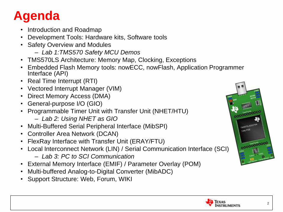
Agenda• Introduction and Roadmap
• Development Tools: Hardware kits, Software tools
• Safety Overview and Modules
– Lab 1:TMS570 Safety MCU Demos
• TMS570LS Architecture: Memory Map, Clocking, Exceptions
• Embedded Flash Memory tools: nowECC, nowFlash, Application Programmer Interface (API)
• Real Time Interrupt (RTI)
• Vectored Interrupt Manager (VIM)
• Direct Memory Access (DMA)
• General-purpose I/O (GIO)
• Programmable Timer Unit with Transfer Unit (NHET/HTU)
– Lab 2: Using NHET as GIO
• Multi-Buffered Serial Peripheral Interface (MibSPI)
• Controller Area Network (DCAN)
• FlexRay Interface with Transfer Unit (ERAY/FTU)
• Local Interconnect Network (LIN) / Serial Communication Interface (SCI)
– Lab 3: PC to SCI Communication
• External Memory Interface (EMIF) / Parameter Overlay (POM)
• Multi-buffered Analog-to-Digital Converter (MibADC)
• Support Structure: Web, Forum, WIKI

3
TMS570LS: Introduction and Roadmap

4
TI Embedded Processing PortfolioMicrocontrollers
32-bitReal-time
C2000
Fixed &
Floating Point
Up to 300 MHz
Flash
32 KB to 512 KB
PWM, ADC,
CAN, SPI, I2C
Motor Control,
Digital Power,
Lighting
$1.50 to $20.00
32-bit M3 ARM
Stellaris-M3
Industry Std
Low Power
<100 MHz
Flash
Up to 512 KB
USB, ENET,
ADC, PWM, CAN
Host
Control
$1.00 to $7.00
16-bit
MSP430
Ultra-low
Power
Up to 25 MHz
Flash
1 KB to 256 KB
Analog I/O, ADC
LCD, USB, RF
Measurement,
Sensing, General
Purpose
$0.49 to $9.00
ARM Core Offerings
DSP
C55x, C64x+
C647x
Leadership DSP
Performance
24,000 MMACS
Up to 3 MB
L2 Cache
1G EMAC, SRIO,
DDR2, PCI-66
Comm, WiMAX,
Industrial/
Medical Imaging
$4.00 to $99+
32-bitARM+
Applications Processors / DSP
Software, Tools & BSPs
32-bitARM+DSP
ARM9/Cortex-A8
plus C64x+
Industry-Std Core +
DSP for Signal Proc.
4800 MMACs/
1.07 DMIPS/MHz
MMU, Cache
VPSS, USB,
EMAC, MMC
Lin/Win O/S +
Video, Imag, MM
$12.00 to $65.00
32-bitR4F ARM
TMS570
Floating Point
Up to 220 MHz
Flash
Up to 3 MB
USB, ENET,
ADC, PWM, CAN
Safety SIL3
Control
$8.00 to $20.00
ARM9
ARM Cortex-A8
Industry-Std
Core,
High-Perf GPP
Accelerators
MMU
USB, LCD,
MMC, EMAC
Linux/WinCE
User Apps
$8.00 to $35.00

5
Airbag
ABS/ESC
Traditional Auto Safety
Growing Transportation
Railway
AeroSpace
Off Road Equipment
Marine Engine
Growing Auto Market
Chassis Domain
HEV/EV
Steering
TMS570: MCU for Transportation

6
TMS570 Setting the Standard for Safety-Critical
Automotive & Transportation Applications
ARM Cortex-R4F with floating point allows
development of complex real-time control algorithms
Safety architecture specifically developed to simplify
SIL3 / ASIL D system implementations
Proven scalability, integration, support and broad
automotive portfolio get customers to market fast
Safety Architecture
System Approach
Real-Time Control

•7
TMSx70 ARM MCU Platform Products Available Today
Value Line Transportation and
Safety MCUs
TMS470M TMS570LS
High Performance Transportation and
Safety MCUs
•Transportation Applications
•Automotive Q100 Qualification
•-40 to 125°C Operation
•FlexRay, CAN Connectivity
•ISO26262 ASIL-D
•IEC 61508 SIL-3
•Cortex-R – over 250 MIPs
•Transportation Applications
•Automotive Q100 Qualification
•-40 to 125°C Operation
•LIN, CAN Connectivity
•ISO26262 ASIL-B
•IEC 61508 SIL-2
• Cortex-M – to 100 MIPS
8
TMS570LS Development Tools

9
MCU Development Support
Software
Development
Support
IDE (Compiler/Linker/Debugger)
• TI Code Composer Studio, iSYSTEM WINIDEA, Lauterbach TRACE32, IAR, KEIL…
AutoSAR 3.0• MCAL and RTE available from Vector
FlexRay™ Drivers• Available from Elektrobit and TTTech Automotive
Hardware
Emulation
Tools
TMS570 supports “Standard ARM” Coresight™ debug components
• ETM with up to 32b external bus and internal FIFO for improved throughput
JTAG debug and trace solutions:
• iSYSTEM, Lauterbach, Sophia, Spectrum Digital
TMS570 Evaluation Modules (EVMs) with integrated JTAG
Prototyping
Tools
TMS570 provides high bandwidth interfaces for bypass and calibration • Vector VX1000 provides up to 3MB/sec using RTP/DMM
Auto-code Generation• Mathworks Real Time Workshop, ETAS ASCET
Bypass proccessing and calibration• Vector VX1000/CANape
CCStudio

10
• Software Included in Each Kit:• CCStudio v4.x IDE: C/C++ Compiler/Linker/Debugger
• HALCoGen Peripheral Driver Generation Tool
• CCS and nowFlashTM Flash Programming Tools
• HET GUI/Simulator/Assembler
• Demo Project/Code Examples
Hercules Development Kits and Roadmap
TMS570LS2x TMS470M TMS570LS3x
Earl
y D
evelo
pm
en
t Communication Expansion Card
Attaches to any ArgoBoard
Argoboard 470M
$695
$79
$200
$99
$79
TMSx70 Development Kits and Roadmap
$79
Evalu
ati
on
TMS570 MDK
$200
Argoboard 570LS
NOW! Q211
NOW!NOW!
Q311
Q311

11
Microcontroller Development Kit (MDK)
• CPU Card
– Connects to COMM Board
– On Board XDS100v2 emulation via USB
– Trace Connectors
– Access to Peripheral Pins
• COMM Board
– Light & Temperature Sensors
– Sensor Interfaces
– FlexRay/CAN/LIN Transceivers
– Color Touch Screen TFT
• DEV Kit
– $695 USD (CPU + COMM Board)
– Orderable Part #TMDX570LS20SMDK
– CCS 4.1 SW IDE included
– Power Supply

12
Microcontroller USB Kit
• Main Features
– USB Powered
– On Board USB XDS100v2 JTAG Debug
– On Board SCI to PC Serial Communication
– Access to Select Signal Pin Test Points
– LEDs, Temp Sensor, Light Sensor and CAN transceiver
– 144 QFP Packaged CPU
• $79 USD
– Orderable Part #TMDX570LS20SUSB
– CCS 4.1 SW IDE included

13
GUI Demos & Code ExamplesIDEs (compilers & debuggers)
TMS570 Software Tools
HALCoGen
• User Input on High Abstraction Level
• Graphical-based code generation
• Easy configuration
• Quick start for new projects
FMzPLL & FPLL Calculators
Easily configure the FMzPLL and FPLLs in
the Hercules family Phase Lock Loop
modules.
HET IDE
• Graphical Programming Environment
• Output Simulation Tool
• Generates CCS-ready software modules
• Includes functional examples from TI
TMS570 Safety MCU Demos:
•Safety Feature Highlight
•Ambient Light Demo
•Temperature Sensor Demo
•LED Light Show
•Source Code Viewable via CCS
now FlashTM Flash Programming Tool
GUI and command line programmer for
loading code into Hercules devices
without an IDE.
GUI-based Code Generation Tools and Other SW Tools
now ECCTM ECC Generation Tool
Command line program for generating
Error Correction Code for Hercules
devices. Can be used in conjunction with
CCSv4
Program/debug TMS570 code
using these IDEs:
•Code Composer Studio v4
•IAR Workbench
•KEIL uVision
RTOS Support
• Micrium uC OS
• Express Logic ThreadX

14
Code Composer Studio v4.1
• Based on Eclipse industry standard for embedded debug tools
– Modern window environment
– Advanced source code editor
– Scalable multi-core/processor environment
– Program and Debug Application via JTAG
– Test Automation via Scripting
• Low cost tools enable developers to easily evaluate and start development
– Develop with CCS for <$100
• TMS570 Debug Features
– 6 Hardware Breakpoints
– Unlimited Software Breakpoints
– Integrated Flash Programming

15
Code Composer Studio Components: Fully Integrated, Easy to Use Development Tools
Source Code View
Target Connection
Source & object files
File dependencies
Compiler, assembler & linker build options
Disassembly
Window
CPU
WindowMemory
Window
Menus and IconsHelp
Watch
Window

16
Features
• User Input on High Abstraction Level
– Graphical-based code generation
– Easy configuration
– Quick start for new projects
• Generates C Source Code
– ANSI Conforming
– Clear, structured, coding style
– Customizable code for user maintenance
• Supported Peripherals
– System Module
– RTI
– GIO
– SCI/LIN
– CAN
– SPI
– ADC
– Timer Co-processor (nHET)
• Interactive Help System
– Describes tool features and functions
– Provides detailed dependency graphs
– Provides useful example code
– Tool tip help available
• Hierarchical project code viewing
HalCoGen:
Hardware Abstraction Layer Code Generator

17
NHET Timer Co-Processor Development Tools
• Graphical Programming Environment
• Output Simulation Tool
• Generates CCS-ready software modules
• Includes functional examples from TI
• Graphical Waveform Viewer
• Input Generation Tool
• Seamless interface to coding tool
• Upgradable to Full SynaptiCAD
NHET ASM
Code
Pin
Selection
Algorithm
Library
Drag & Drop
Instructions
Waveform
View
NHET
Registers

18
Tools Roadmap
External Tools:
• IDE’s
• Lauterbach, iSystems, IAR, Keil / ARM, Hitex
• Compiler
• IAR, ARM, GCC, …
• Emulator
• Spectrum Digital, Lauterbach, iSystems, IAR, Keil, Blackhawk,
Segger, Signum Systems, …
• Operating System
• ETAS, Vector, Sciopta, Wittenstein, Micrium, …
• AutoSAR
• Vector, ElectroBit
• Trace / Calibration
• Lauterbach, iSystems, Vector, ETAS, Sophia Systems
• Production Flash Programming
• BP Microsystems, Data-IO
• Rapid Prototyping
• Matlab/Simulink, dSpace

19
Safety Features on TMS570LS
Microcontrollers

What is Functional Safety?• Basic Functional Safety Concepts:
– All systems will have some inherent, quantifiable failure rate. It is not possible to develop a
system with zero failure rate.
– For each application, there is some tolerable failure rate which does not lead to unacceptable risk.
– Acceptable failure rates vary per application, based on the potential for direct or indirect physical
injury in the event of system malfunction.
– Categories can be developed to quantify similar levels of risk. These are known as Safety
Integrity Levels, or SILs.
• IEC 61508 Definition:
– Safety is the freedom from unacceptable risk of physical injury or of damage to the
health of people, either directly, or indirectly as a result of damage to property or to
the environment.
– Functional Safety is part of the overall safety that depends on a system or equipment
operating correctly in response to its inputs.
– For example, an overtemperature protection device which de-energizes a motor
before it can overheat is an example of functional safety. A specialized motor which
can withstand high temp without failure IS NOT functional safety.
• ISO 26262 Definition:
– Absence of unacceptable risk due to hazards caused by mal-functional behavior of
electrical and/or electronic systems
20

Safety Failures and their Causes
• Failures in a functional safety system can be broadly classified into
two categories: systematic and random failures
• Systematic Failures
– Result from a failure in design or manufacturing
– Often a result of failure to follow best practices
– Rate of systematic failures can be reduced through continual and
rigorous process improvement
• Random Failures
– Result from random defects inherent to process or usage condition
– Rate of random failures cannot generally be reduced; focus must
be on the detection and handling of random failures in the
application.
•2/4/2011 •Texas Instruments NDA Restrictions

Functional Safety Standards Across Industries
IEC 61508
(meta-standard)
EN 50128
(railway)
IEC 60601
(medical
equipment)
IEC 61511
(process
industry)
IEC 62061
(machinery)
RTCA/DO-178B
(aerospace)
IEC 50156
(furnaces)
IEC 60880
(nuclear power
stations)
ISO 26262
(automotive)
• IEC 61508 is a 'meta standard‟ in the sense that it has to be used as a
basis of sector-specific standards, but where these do not yet exist, it is
also intended for direct use.– e.g. for heavy trucks for which the ISO 26262 does not (yet) apply
22

ISO 26262
• ISO 26262 (Road Vehicles) is
under development to meet
automotive industry specific
needs as an IEC 61508
replacement.
• Standard is in definition (ISO-
TC22-SC3-WG16).
– Draft available June 2009
– Expected release mid 2011.
– TI is participating in the US
working group.
IEC61508
SIL Levels
1
2
3
4
ISO26262
ASIL Levels
A
B
C
D
ISO26262 defines 4 safety integrity levels (ASIL-A,B,C,D)
There is no direct correlation between IEC61508 SIL and ISO 26262 ASIL levels

ISO 26262
• Timeline:
– Standard is currently in DIS (draft international standard) phase
– FDIS (final draft international standard) late 2010
– IS (international standard) should be ratified mid 2011
• Status
– DIS does not have acceptable maturity
– DIS/FDIS under major pressure to complete in minimum time.
– Many changes expected between DIS to FDIS and FDIS to IS
– TI is participating in US TAG; only semiconductor vendor present
• Co-authored major re-write of informative section on hardware faults and
diagnostics to be considered for safety analysis (-5 Annex D)
• GM, Yogitech, and Renault participating in review/editing

25
Exida Has Certified TMS570LS20216S
IEC 61508SIL3 Capable

26
Rationale of TI Safety Concept
• “Safe Island” approach
• Region of device common to all safety functions is heavily protected by hardware diagnostic measures
– CPU
– CPU Interrupts
– System control of power, reset, clock
– OS critical IP: DMA, OS timer
• Once a known safe region can be guaranteed, logic in this region can be used to provide diagnostic coverage on other regions
• This partition has shown to give strong safety metrics while minimizing impact of safety on system BOM cost

27
Safety Features Overview
• Dual Core Lockstep - Cycle by Cycle CPU Fail Safe Detection
• CPU Self Test Controller requires little S/W overhead
• ECC for Flash / RAM Evaluated inside the Cortex R4F
• Parity on all Peripheral, DMA and Interrupt controller RAMS
• Memory BIST on all RAMS allows fast memory test at startup
• On-Chip Clock and Voltage Monitoring
• Error Signaling Module w/ External Error Pin
• CRC, IO Loop Back, ADC Self Test, …
• 3 domains identified:
– Not safety critical functions (black)
– Core functionality common to all Safety Instrumented Functions (red)
– Peripheral functionality specific to specific Safety Instrumented Functions (blue)

28
1oo1D Dual Core Safety Concept
• Unique design to reduce common cause failures (βIC)
– Second CPU mirrored and rotated
– Minimum distance 100µm between CPUs
– Cycle delayed lockstep
– Guard ring per CPU
– Duplicated clock tree per CPU
• CPU Compare Module
– Self-test capability
– Self-test error injection/error forcing
– Output error injection
Output + Control
Cycle Delay
> 100um
Dedicated
Power Ring
Cycle DelayCCM
Compare
Error
Input + Control
Self
Test

29
STC
DBIST
CNTRL
CPU1
ROM
Clock
controller
ESM
PCR
Test
controller
CPU_nRESET
misr_in1
ERR
DBIST
CNTRL CPU2
CCM
misr_in2
ROM
interface FSM
Clock cntrl
STC BYPASS/
ATE Interface
REG Block
&
Compare
BlockVBUSP
interface
• Provides High Diagnostic Coverage
• Significantly Lowers S/W and Runtime Overhead
• No SW BIST (Built In Self Test) Code overhead in Flash
• Simple to configure and start BIST via register
CPU Self Test Controller (STC/LBIST)

30
Flash / RAM ECC Protection
Cortex-R4F
Flash RAM
• ECC evaluated in the Cortex R4F CPU
– Single Bit Error Correction and Double Bit Error Detection
– ECC evaluated in parallel to processing data/instructions
– No latency or performance impact
– Protects Busses from CPU to Flash and RAM
4 ECC Bits32 Data Bits
32 Data Bits
64 Inst.
8 ECC
ECC Logic
8 Stage
Pipeline
Error
64 Data
8 ECC
4 ECC Bits

31
Programmable Memory BIST (PBIST)
• All on-chip RAMS can be tested
• Run at startup
• Multiple Memory Test Algorithms
• Detects multiple failure modes
PBIST
Controller
Data
Logger
Extblock
Cfgblock
VBUS I/f
Tester I/f RAM
Data
path/
CollarsTo / From
Memories
(RAM
groups)
ROMblock
ROM I/f
Functional
Read/Write
Datapath

32
Safety Aspects of Network Interfaces
• Networked peripherals (FlexRay, DCAN, and SCI/LIN) are considered grey-channel / black-channel communications
• In such communications application level protocols (time redundancy, CRC in data packet, etc.) are necessary
• When such assumption is made, the Dangerous Undetected Failure from the network is effectively not measurable (<0.001 Failure In Time (FIT))
• Detailed fault data available upon request

33
Error Signaling Module (ESM)
ESM
Errors for Group 1
Errors for Group 2
Errors for Group 3
To Interrupt
ManagerINTEN INTLVL
Low Level Interrupt
Handling
High Level Interrupt
Handling
LOW TIME
COUNTER PRELOAD
LOW TIME
COUNTER
nERROR pin
ERROR
SIGNAL
CONTROL
34
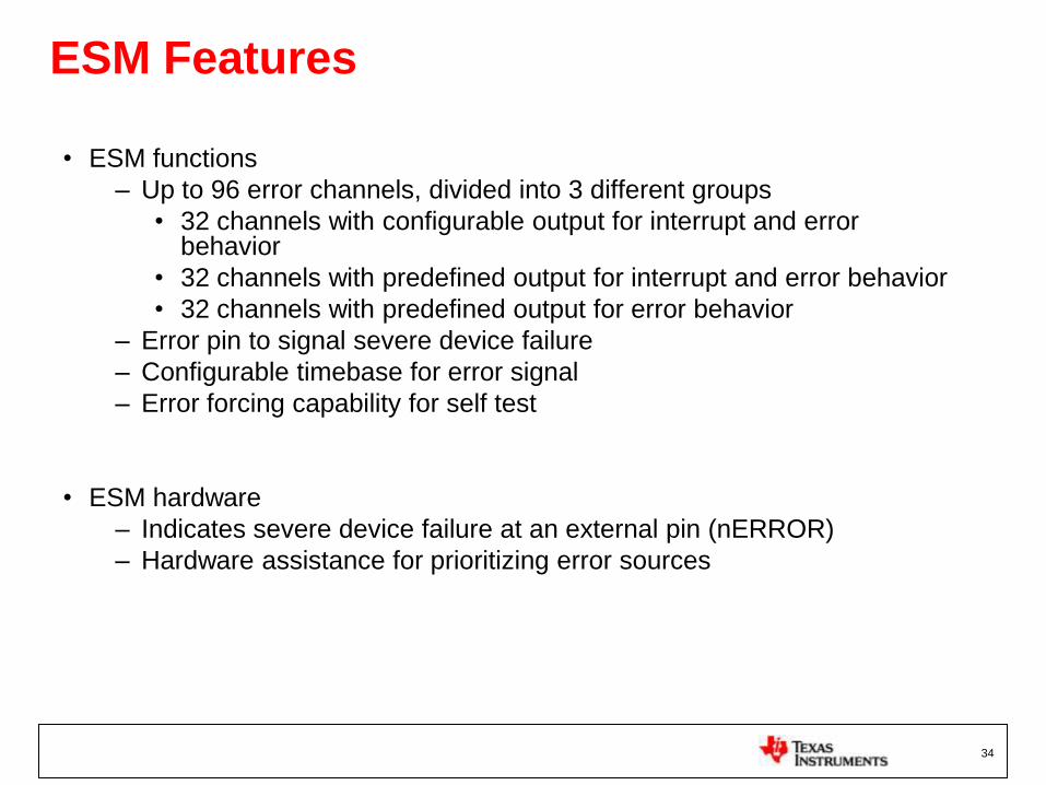
ESM Features
• ESM functions
– Up to 96 error channels, divided into 3 different groups
• 32 channels with configurable output for interrupt and error behavior
• 32 channels with predefined output for interrupt and error behavior
• 32 channels with predefined output for error behavior
– Error pin to signal severe device failure
– Configurable timebase for error signal
– Error forcing capability for self test
• ESM hardware
– Indicates severe device failure at an external pin (nERROR)
– Hardware assistance for prioritizing error sources

35
Additional Safety Features
• Supply monitor (VMON)
– Asserts reset if core or I/O supply exceeds defined min/max thresholds
• Clock monitoring
– Oscillator monitor
• Detects failure if oscillator frequency exceeds defined min/max thresholds
• Selectable hardware response on oscillator fail
– PLL slip detector
• Indicates PLL slip if phase lock is lost
• Selectable hardware response on PLL slip
• Internal backup „low power oscillator‟ (LPO) clock source
– External clock prescaler
• Allows external monitoring of CPU clock frequency
• Dedicated Memory Protection Units for each bus master

36
LAB1: TMS570LS Safety Features Demo

37
Lab1: TMS570 Safety MCU Demos

38
TMS570LS Architecture Overview:
Memory Map, Clocking, Exceptions
39
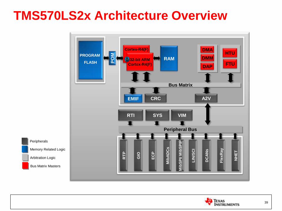
TMS570LS2x Architecture Overview
Fle
xR
ay
DC
AN
s
Mib
SP
I/ M
ibS
PIP
Mib
AD
Cs
NH
ET
GIO
EC
P
Peripheral Bus
RTI SYS VIM
Bus Matrix
CRC A2V
RAM
LIN
/SC
I
PO
M
EMIF
PROGRAM
FLASH
HTU
FTU
DMA
DMM
DAP
RT
P
Cortex-R4(F)
32-bit ARM
Cortex-R4(F)
Bus Matrix Masters
Peripherals
Arbitration Logic
Memory Related Logic

40
Memory Map
0x00000000
0x00 1FF FFF
0x08000000
0x080 27FFF
CRC0xFE000000
0xFEFFFFFF
0xFF000000
0xFFF7FFFF
SYSTEM Modules0xFFF80000
0xFFFFFFFF
0x0 0400000
0x00 4FFFFF
0x0 8400000
0x084 27FFF
EMIF (256MB)
0x60000000
0x6FF FFFFF
CS1
CS0
CS2
CS3
0x60000000
0x603FFFFFPOM (4MB)
TMS570LS20216
0x20000000
0x20 1FF FFF
0x2 0400000
0x20 4FFFFF
Flash (2MB)
Flash - ECC
RAM (160kB)
RAM - ECC
Flash (2MB) (mirrored image)
Flash – ECC (mirrored image)
Peripherals
41
Clock Sources and Domains
/1..64 X92..184 /1..8 /1..32
Low Power
Oscillator
/1..2 X1..15 /1..8
OSCIN
/1..16
/1..16
0
1
4
5
6
GCLK (to CPU)
HCLK (to System Bus)
VCLK (to Peripheral Bus)
VCLK2 (to NHET/HTU)
0
1
4
5
6
VCLK
VCLKA1 (to DCANx)
0
1
4
5
6
VCLK
VCLKA2 (to FlexRay/FTU)
0
1
4
5
6
VCLK
/1,2,4, or 8
RTI1CLK (to RTI)
Clock Source #

42
Frequency Modulated PLL (FMzPLL)
REFCLKDIV PLLDIV
PLLMUL
ODPLL PLLCTL2
PLLCTL1
PLLCLK, fPLLOSCIN, fOSCIN
Where
NR – Reference Clock Divider ratio (REFCLKDIV)
NF – PLL feedback divider ratio (PLLMUL), 92 .. 184
ODPLL – PLL output divider ratio (ODPLL), 1 .. 8
R – PLL Divider Ratio (PLLDIV), 1 .. 32
Configure FMzPLL using PLLCTL1(0x70) and PLLCTL2 (0x74) registers of System frame1 (0xFFFF_FF00)
The output frequency of the FMzPLL is given by:
NR
/1..64
NF
X92..184
ODPLL
/1..8
R
/1..32
PLL

43
FMzPLL Calculator
• Can be used to determine PLLCTL1 and 2 register values based on the entered PLL and FM option settings
• Can be used to determine the PLL and FM settings based on the entered PLLCTL1 and 2 register values

44
Secondary Non-Modulating PLL (FPLL)
Where
NR – Reference Clock Divider ratio (REFCLKDIV), /1 .. 2
NF – PLL feedback divider ratio (PLLMUL), X1 .. 15
R – PLL Divider Ratio (PLLDIV), /1 .. 8
Configure FPLL using FPLLCTL(0x00) register of System frame2 (0xFFFF_E100)
The output frequency of the FPLL is given by:
/NR
/ 1 .. 2
OSCIN
PLL
x NF
x 1 .. 15
/R
/ 1 .. 8
PLLCLK

45
FPLL Calculator
• Can be used to determine FPLLCTL register values based on the entered PLL settings
• Can be used to determine the PLL settings based on the entered FPLLCTL register value

46
Low Power Modes
• Doze Mode
– Highest power consumption among low power modes
– Fastest from wake up event to full-speed operation
– Main oscillator remains active and clocks RTI module
– Wake up from RTI or external sources (CAN, LIN, SCI, GIO, reset)
• Snooze Mode
– Power consumption near minimum
– Allows fast wake up using internal reference oscillator
– Only internal reference oscillator remains active and clocks RTI module
– Wake up from RTI or external sources (CAN, LIN, SCI, GIO, reset)
• Sleep Mode
– Lowest power consumption among low power modes
– Slowest from wake up event to full-speed operation
– All clock sources and clock domains are disabled
– Wake up only from external sources (CAN, LIN, SCI, GIO, reset)

47
Low Power Modes Summary
High freq.
oscillator
Internal low
freq. clock
RTI
clock
GCLK HCLK VCLKP VCLK2 VCLKA1 VCLKA2 PLL Flash
banks
Flash
pumps
on on on off off off off off off off off off
High freq.
oscillator
Internal low
freq. clock
RTI
clock
GCLK HCLK VCLKP VCLK2 VCLKA1 VCLKA2 PLL Flash
banks
Flash
pumps
off on on off off off off off off off off off
LPO Internal low
freq. clock
RTI
clock
GCLK HCLK VCLKP VCLK2 VCLKA1 VCLKA2 PLL Flash
banks
Flash
pumps
off off off off off off off off off off off off
Doze Mode:
Snooze Mode:
Sleep Mode:

48
Reset Sources
• Power-on Reset
– Asserted by external voltage supervisor, or by internal voltage monitor
• Oscillator fail
– Asserted by internal clock monitor when enabled by software
• CPU Reset
– Asserted by CPU self-test controller after LBIST operation completes
• Software Reset
– Asserted by software writing to the exception control register
• External Reset
– Asserted by external circuitry driving the warm reset (nRST) signal LOW
• Debug Reset
– Asserted by ICEPICK JTAG module

49
TMS570LS: Flash Tools

50
nowECC
<return_value> nowECC [options] -i <input_file> [-o <output_file>]
• Generates ECC data for program flash
• Command-line executable
• Return value = 0 indicates no error during operation
– Separate error codes to differentiate each type of error
• Input_file is only required parameter
– Can be Extended Tektronix, Intel Hex, Motorola-S, COFF or ELF format
• Output_file specifies the name of the output file to be generated
– If no name is specified, ECC is appended to input file specified

51
Options for Flash Programming
• On-board programming using nowFlash/Code Composer Studio v4.x
– Requires JTAG connection
– Emulators Supported:
• Blackhawk BHUSB560M
• Spectrum Digital XDS510PP, XDS510PP+, XDS510USB, XDS560RUSB
• Signum JTAGjet
• Texas Instruments SPI525, XDS100v2, XDS560
• On-board programming via customer boot-loader code
– Must use Texas Instruments released API routines
– Multiple communication interfaces can be used
– Necessary to validate program and erase routines
• Off-board programming
– Single-device or Concurrent programming
– Supports high degree of automation

52
nowFlash Flash Programming Tool
• PC-based software tool: GUI + command line executable
• Communicates with microcontroller via JTAG
• Can be used to program, erase, read, or verify flash memory
• Also supports execution of custom code out of RAM (from command line only)

53
Flash Application Programming Interface (API)
• Distributed only as an object library file
• Supports flash operations out of on-chip RAM
• Supports operations at max specified device clock frequency
• Library routines for
– Blank check
– Compaction
– Erase
– Program zeros
– Program data
– Calculate checksum
– Verify
• Routines also manage ECC


![Role of planting depth and mulching on growth and yield ... · Ilyas & Ayub 1437 exceed17 0C [3] and the optimal temperature for tuber bulking ranges between 14 0C and 22 0C. Higher](https://img.pdfslide.us/doc/110x75/5b91fe9509d3f210288cefcd/role-of-planting-depth-and-mulching-on-growth-and-yield-ilyas-ayub-1437.jpg)


![BaanERP 5[1].0c Manufacturing - Production Order Costing](https://img.pdfslide.us/doc/110x75/54fe5a7f4a7959422b8b4ff4/baanerp-510c-manufacturing-production-order-costing.jpg)