Embed Size (px)
Citation preview

11/01/061
© John Day, 2010All Rights Reserved
An Introduction to RINAOr
How I Learned to Stop Worrying and Love the Internet
FutureNet Tutorial Part I
John DayMay 2010
Good architecture, like good science, ismaximizing the invariances and minimizing thediscontinuities.

11/01/062
© John Day, 2010All Rights Reserved
We Got Trouble!Right Here in River City

11/01/063
© John Day, 2010All Rights Reserved
The Internet is FacingSevere Problems: I
• Security is essentially non-existent.– Excuse: No one considered it in the early days
• Security wasn’t a concern for a military-funded network?– Actual: Systematically weak design (hacker mentality)
• Router table size is growing exponentially– Excuse: Memory is cheap– Actual: No longer on Moore’s Law, it is getting expensive and caused by
• No support for multihoming– Excuse: not that many hosts need it, and we can kludge it
• A military-funded network doesn’t care about suvrivability?– Actual: Since when is 107 small, and the kludge doesn’t scale.
• It isn’t 107, with Smart Grid it is more like 1010.

11/01/064
© John Day, 2010All Rights Reserved
The Internet is FacingSevere Problems: II
• Mobility is cumbersome and doesn’t scale– Excuse: What do you mean? It works. . . . . Sort of.– Actual: With only physical addresses, hard to do “re-locatable” addressing
• Congestion Control keeps Utilization around 30%– Excuse: There is great congestion control in TCP . . . Sort of. Bandwidth is
Cheap don’t worry about it.– Actual: Any control theory book says put feedback as close to the resource
as possible. TCP puts it as far away as possible.• Quality of Service is difficult to do.
– Excuse: Net neutrality requires that all traffic be treated equally– Actual: Net neutrality is political cover for their inability to find solution.
• Notice: Running out IP addresses was not listed– Not a problem. A global address space is not required

11/01/065
© John Day, 2010All Rights Reserved
And if that Weren’t Bad Enough
Much of What is Believedabout the Internet is Myth

11/01/066
© John Day, 2010All Rights Reserved
Myths of the Internet: I• The Internet is an Engine of Innovation.
– The Internet has in a real sense been stagnant since the late-70s– Living on Moore’s Law and Band-aids
• Lots of Innovation on top of the Internet, but even that has begun to wane.
• The Internet has decentralized administration. No one owns the Internet.– Actually, Same as the global PSTN, just no sexy name.
• The IETF is a Grass-Roots Democracy.– Actually, It most closely Resembles the Communist Party.
• IETF meeting is the Party Congress; IESG is the Politburo– Designed to be dominated by an elite, just not the one they had in mind.
• The Internet is based on the ARPANET– Actually, It is based on the French network CYCLADES– The ARPANet technology was abandoned.

11/01/067
© John Day, 2010All Rights Reserved
Myths of the Internet: II
• The Internet is not an internet, but a catenet.– Ceased to be an Internet on January 1, 1983.
• The Internet is a dumb network.– Actually, it keeps maximal state in the network, not minimal.
• The Internet has decentralized routing.– Actually, in most ISPs routes are statically allocated.
• IP is the Internet Protocol.– That is what the letters stand for but at best it is a subnet protocol.
• More likely just a header fragment
• IP addresses name the host.– No, they name an interface to the host.
• TCP isn’t perfect, but it is good enough.– Every design decision is not just wrong but makes something else worse.
One thing it got right was destroyed creating IP.

11/01/068
© John Day, 2010All Rights Reserved
The Reality is Quite Different
• If the Internet were an Operating System, it would have more incommon with DOS, than UNIX.
• Imagine trying to use a modern computer with only physical memoryaddresses.
• That is the Internet today.

11/01/069
© John Day, 2010All Rights Reserved
Need to Do Something About It• For the Past Decade, DARPA, NSF, and numerous conferences, workshops,
and summits have discussed and done research on a “Future InterNet Design.”– So far they have come up dry, nothing, nada.
• Similar efforts in Europe and Asia.‒ Same result . Isn’t groupthink wonderful?
• No closer to an answer now than a decade ago.– “Rough consensus and running code” doesn’t exactly foster the kind of thought
required to uncover theory.• The field is no longer a science, but a craft.
– They have been asking “What to build?”– Not asking, “What don’t we understand?”
11/01/0610
© John Day, 2010All Rights Reserved
Guiding “Principles” Aren’t Much Help• Soft State/Hard State
– All properly designed protocols are soft state; only some databaseoperations are hard state. A specious distinction
• Loc/Id Split– Attempt to avoid the obvious solution. Mostly post IPng trauma.– Continues to route to the wrong place
• Fate Sharing– Mostly used as a rug . . . to sweep under.
• End-to-End Principle– At best a lemma. More a statement of desire, by focusing attention on the
dichotomy of the middle vs the edge, it obscures the point.– Hence becomes an impediment to finding a path forward.

11/01/0611
© John Day, 2010All Rights Reserved
The Myths and “Principles” are the MajorBarrier to FINDing an Answer
• The Answer has been clear since the mid-90s.
• And it is very simple:
• Networking is IPC and only IPC

11/01/0612
© John Day, 2010All Rights Reserved
CYCLADES had Shown the Way
Physical
Data Link
Network
TransportApplication
Host or End System
Router
An Architecture with Alternating Layers of Relaying and ErrorControl of Increasing Scope Seemed to Make a Lot of Sense.
11/01/0613
© John Day, 2010All Rights Reserved
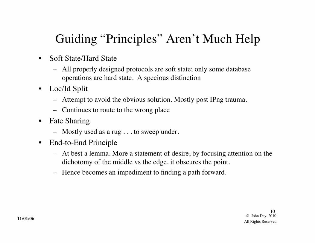
So We Went With It
And While Better It Wasn’t The Full Answer
Application
Presentation
Session
Transport
Network
Data Link
PhysicalPhysical
Transport
MACLLC
SNACSNDC
SNIC
Application
Presentation
Session
But As Things Developed Things go more complex

11/01/0614
© John Day, 2010All Rights Reserved
Meanwhile the Internet Never Got Past
We Were Missing Something, but What was It?Were Layers the Wrong Model?
Application
TCP
IP
Subnet
Or do whateveryou want
Or do whateveryou want

11/01/0615
© John Day, 2010All Rights Reserved
Probably Not, Lets Go Back to Basics
• Start simple and incrementally introduce new conditions.– Taking Imre Lakatos’ Proofs and Refutations as a model.
• We are going to cover ground we all know.– Or at least we think we do. (I thought so)
• As we do, think about what is required when– the order is not what you might expect.– But the implications are even more interesting.

11/01/0616
© John Day, 2010All Rights Reserved
1: Start with the BasicsTwo applications communicating in the same system.
Communication withina Single Processing System
IPC Facility
ApplicationProcesses
PortIds
A BApplication
Flow

11/01/0617
© John Day, 2010All Rights Reserved
How Does It Work?
1) A invokes IPC to create a channel to B; a = Allocate (B, QoS);2) IPC determines whether it has the resources to honor the request.3) If so, IPC allocates port-id a and uses “search rules” to find B and determine
whether A has access to B.4) IPC may cause an instance of B to be created. B is notified of the IPC request from
A and given a port-id, b.5) If B responds positively, and IPC notifies A (the API could be blocking in which
case the assignment of the port-id, a would be done now).6) Thru n) Then using system calls A may send PDUs to B by calling Write(a, buf),
which B receives by invoking Read(b, read_buffer)7) When they are done one or both invoke Deallocate with the appropriate parameters
IPC Facility
ApplicationProcesses
PortIds
A BApplication
Flow

11/01/0618
© John Day, 2010All Rights Reserved
2: Two Application Communicatingin Distinct Systems
IPC-Facility
ApplicationProcesses
Systems

11/01/0619
© John Day, 2010All Rights Reserved
How Does It Work Now?
IAP IAP
1) A invokes IPC to create a channel to B; a = Allocate (B, QoS);2) IPC determines whether it has the resources to honor the request.3) If so, IPC uses “search rules” to find B. and determine if A has access to B.
- Management of name space is no longer under the control of a single system.- Each system no longer knows all available applications.
– Local Access Control can no longer be relied on to provide adequate authorization andauthentication.
• Need a protocol to carry application names and access control information.– Lets call it the IPC Access Protocol
ApplicationProcesses
PortIds

11/01/0620
© John Day, 2010All Rights Reserved
What Does “IAP” Look Like?
• Simple Request/Response Protocol– IAP-Req(Dest-Appl-name, Src-Appl-name, QoS params, Src-Capability)– IAP-Resp(Dest-Appl-name, Src-Appl-name, QoS params, result)
• How do we know when to use it?– If the application isn’t here, it must be there!
• But we have a problem. How do we get it there?
Op Dest Appl Name Src Appl Name QoS & Policies Capability

11/01/0621
© John Day, 2010All Rights Reserved
Getting from A to B• We knew this was going to be a problem sooner or later.• We need to be able to send information from A to B.• And we know:
– Bad things can happen to messages in transit. Protection against lost orcorrupted messages
• This can be expensive– Receiver must be able to tell sender, it is going too fast. We need Flow
Control, and– We have lost our means of synchronization:
• No common test and set means shared memory can no longer be used• Must create shared state between two systems. An explicit synchronization
mechanism is required.• We need some kind of Protocol for Error and Flow Control.

11/01/0622
© John Day, 2010All Rights Reserved
What Would an EFCP Look Like?
• Symmetric Protocol to establish error and flow control• Transfer PDU
• Ack and Flow Control PDU types
Op Seq # CRC Data
Op Seq # CRC Op Seq # CRC CreditAck

11/01/0623
© John Day, 2010All Rights Reserved
How Does It Work Now?
DistributedIPC FacilityEFCP EFCP
IAP IAP
1) A invokes IPC to create a channel to B; a = Allocate (B, QoS);2) IPC determines whether it has the resources to honor the request.3) Send IAP Request to access B, creating an EFCP connection and determines if A has
access to B.4) IPC may cause B to be instantiated. B is notified of the IPC request from A and given a
port-id, b.5) If B responds positively, and IPC notifies A with a different port-id, a.6) Thru n) Then using system calls A may send PDUs to B by calling Write(a, buf), which B
receives by invoking Read(b, read_buffer) over the EFCP connection7) When they are done one or both invoke Deallocate with the appropriate parameters
Just Like Before . . . .More or Less
ApplicationProcesses
PortIds

11/01/0624
© John Day, 2010All Rights Reserved
Two Applications in Two Systems RequiredThree New Concepts
• An Application Name Space that spans both systems. (not really new)– Should be location-independent in general so that applications can move.
• A Protocol to carry Application Names and access control info– Applications need to know with whom they are talking– IPC must know what Application is being requested to be able to find it.
• For now, if the requested Application isn’t local, it must in the other system.• A Protocol that provides the IPC Mechanism and does Error and Flow
Control.– To maintain shared state about the communication, i.e. synchronization– To detect errors and ensure order– To provide flow control
• Resource allocation can be handled for now by either end refusingservice.

11/01/0625
© John Day, 2010All Rights Reserved
EFCP EFCPEFCP EFCP
3: Simultaneous CommunicationBetween Two Systems
i.e. multiple applications at the same time
• To support this we have multiple instances of the EFCP.
Will have to add the ability in EFCP to distinguish one flow from another.Typically use the port-ids of the source and destination.
Op Seq # CRC Data
Connection-id
Src-portDest-port
Also include the port-ids in the information sent in IAP to be used in EFCPsynchronization (establishment).
EFCP EFCP

11/01/0626
© John Day, 2010All Rights Reserved
Simultaneous CommunicationBetween Two Systems
i.e. multiple applications at the same time
• In addition to multiple instances of the EFCP.
Mux Mux
Will also need an application to manage multiple users of a single resource.
EFCP EFCPEFCP EFCPEFCP EFCP

11/01/0627
© John Day, 2010All Rights Reserved
Multiple Instances of IPC
• New Concept: a multiplexing application to manage the singleresource, the physical media.
• The multiplexing application will need to be fast, its functionalityshould be minimized, i.e. just the scheduling of messages to send.– To provide QoS, we use the EFCP and scheduling by the Mux.
• To do resource allocation, we will just let the other side refuse if itcan’t satisfy the request.
• Application naming gets a bit more complicated than just multipleapplication-names.– Must allow multiple instances of the same process

11/01/0628
© John Day, 2010All Rights Reserved
IPC to Support SimultaneousCommunication between Two Systems
EFCP
Mux
IAP
Physical Media
Distributed IPC-Process
11/01/0629
© John Day, 2010All Rights Reserved
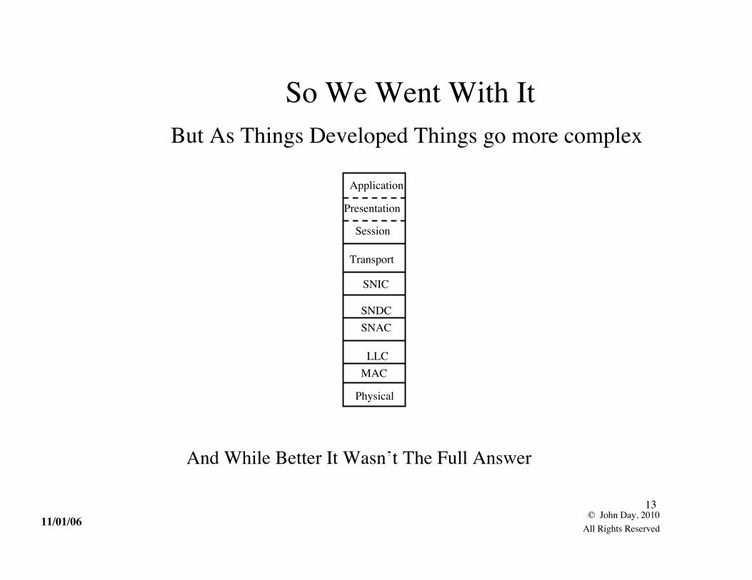
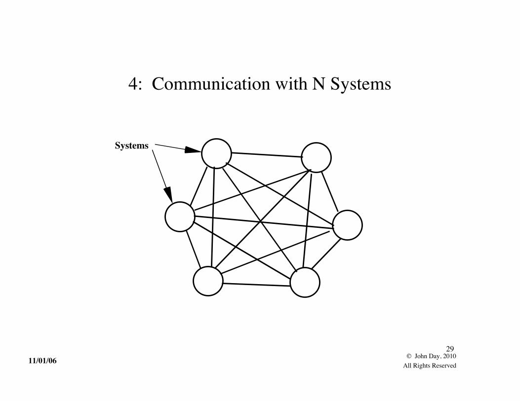
Systems
4: Communication with N Systems

11/01/0630
© John Day, 2010All Rights Reserved
Replication Entails More Management• Separate Multiplexing Application for each physical media interface.
• IPC can find the destination by choosing the appropriate interface.
• If enough applications, create a Directory to remember what is where,i.e. what application names are at the other end of which interfaces.
• Same local names can be used to keep track of which EFCP-instances(port-ids) are bound to which Multiplexing Application.
• With many destinations, may need to coordinate resource allocationinformation within our distributed IPC Facility.
11/01/0631
© John Day, 2010All Rights Reserved
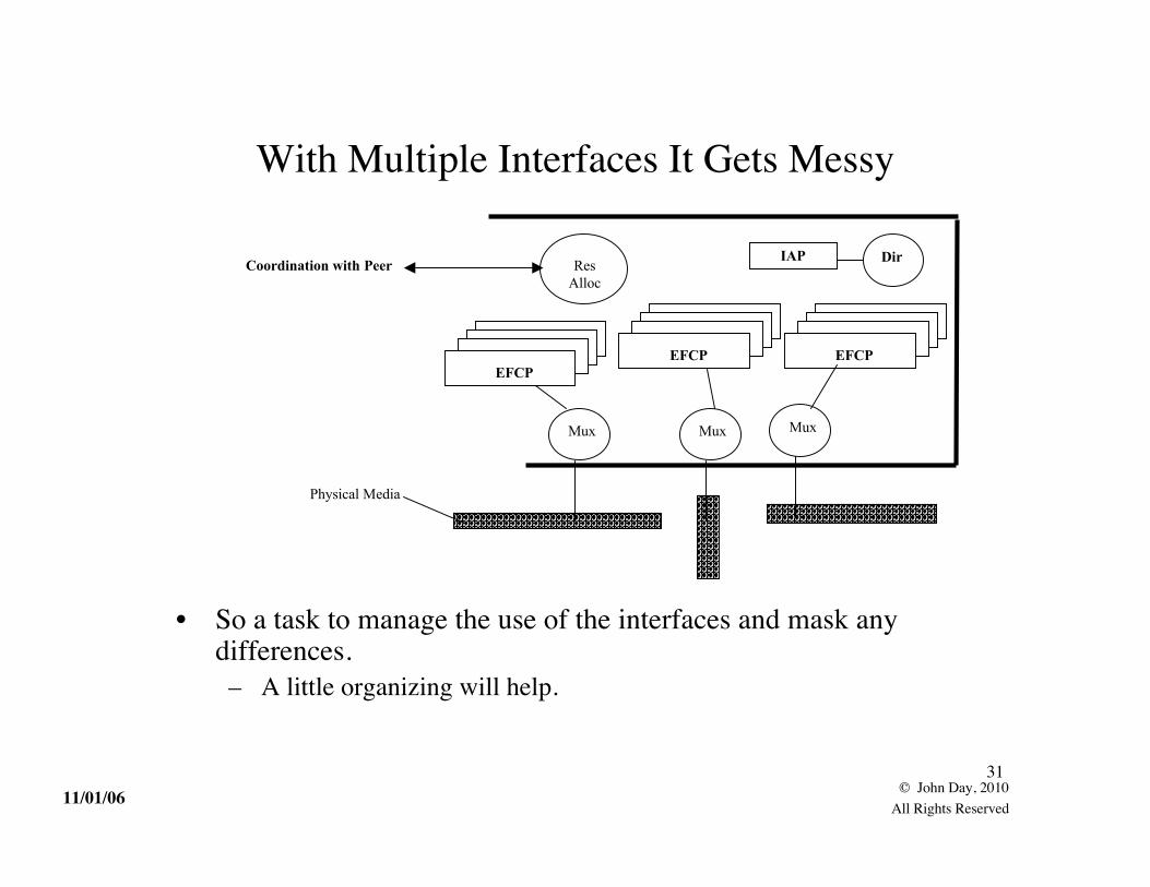
With Multiple Interfaces It Gets Messy
• So a task to manage the use of the interfaces and mask anydifferences.– A little organizing will help.
EFCP
IAP DirResAlloc
Physical Media
Coordination with Peer
Mux
EFCPEFCP
MuxMux

11/01/0632
© John Day, 2010All Rights Reserved
There is Some Common Structure
• We can organize interface IPC into modules of similar elements.• Each one constitutes a Distributed IPC Facility of its own.
– As required, consists of IAP, EFCP, Multiplexing Application, Directory,Per-Interface Resource Allocation
• Then we just need an application to manage their use and moderateuser requests.
IAP Dir
ResAlloc
Physical Media
Coordination with Peer
EFCP
Mux

11/01/0633
© John Day, 2010All Rights Reserved
A Little Re-organizing
So we have a Distributed IPC Facility for each Interface and anapplication over all of them to manage their use and to give the usera common interface, a Virtual IPC Facility?
IAP
DirMux
A Virtual IPC Facility? ResAlloc

11/01/0634
© John Day, 2010All Rights Reserved
BUT
• This fully connected graph approach isn’t going to scale very well andis going to get very expensive.– And not everyone needs to talk to everyone else all the time.
• Need to do something better.

11/01/0635
© John Day, 2010All Rights Reserved
Host Systems
Dedicated IPCSystems
5: Communicating with N Systems(On the Cheap)
By dedicating systems to IPC, reduce the number of lines required and even outusage by recognizing that not everyone talks to everyone else the same amount.
11/01/0636
© John Day, 2010All Rights Reserved
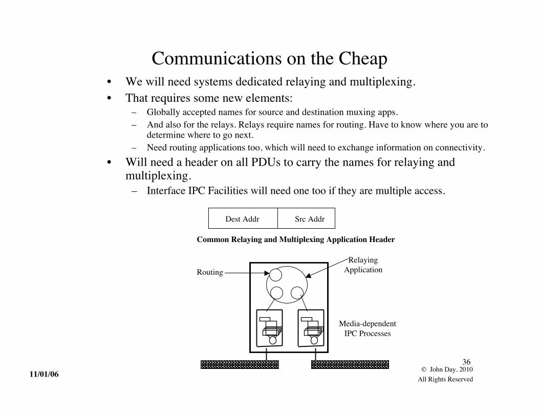
Communications on the Cheap• We will need systems dedicated relaying and multiplexing.• That requires some new elements:
– Globally accepted names for source and destination muxing apps.– And also for the relays. Relays require names for routing. Have to know where you are to
determine where to go next.– Need routing applications too, which will need to exchange information on connectivity.
• Will need a header on all PDUs to carry the names for relaying andmultiplexing.
– Interface IPC Facilities will need one too if they are multiple access.
Dest Addr Src Addr
Common Relaying and Multiplexing Application Header
RelayingApplication
Media-dependentIPC Processes
Routing

11/01/0637
© John Day, 2010All Rights Reserved
Communications on the Cheap• But relaying systems create problems too.
– Can’t avoid momentary congestion from time-to-time.– Annoying bit errors can occur in their memories.
• Will have to have an EFCP operating over the relays to ensurerequired QoS reliability parameters.– Our virtual IPC Facility isn’t very virtual.
EFCP EFCP
RelayingApplicationRelaying
PM

11/01/0638
© John Day, 2010All Rights Reserved
The Big Picture
RelayingAppl
EFCPEFCP
EFCP EFCP EFCP EFCP EFCP EFCP
MuxMux
User Applications
This should look familiar.
Data LinkLayer
NetworkLayer
TransportLayer
ApplicationLayer
But this is half waybetween a bead-on-a-
string model and alayered model
PhysicalLayer

11/01/0639
© John Day, 2010All Rights Reserved
The IPC Model(A Purely CS View)
RelayingAppl
EFCPEFCP
EFCP EFCP EFCP EFCP EFCP EFCP
MuxMux
User Applications
Distributed IPC
Facilities

11/01/0640
© John Day, 2010All Rights Reserved
Summary
• “Networking is InterProcess Communication”– . . . . and only IPC.
• The quote is Bob Metcalfe, 1972. (The rest is mine.)
• A layer is a distributed application that manges IPC consisting of acollection of SDU protection, muxing, EFCP, and their associatedrouting and resource management tasks.
• This is a distributed computing problem, not a “telecom” problem.
• And this Distributed IPC Facility repeats.
• This constitutes a basis for a general theory of networking.
11/01/0641
© John Day, 2010All Rights Reserved
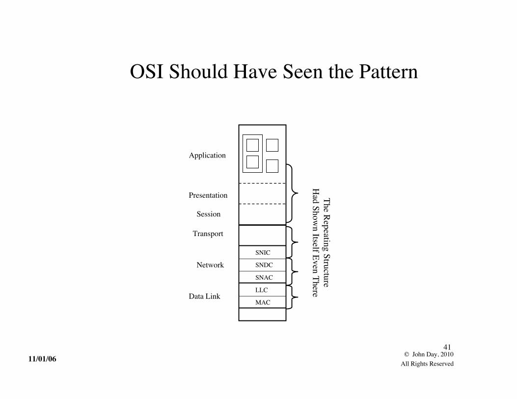
OSI Should Have Seen the Pattern
SNIC
SNDC
SNAC
LLC
MAC
Application
Session
Presentation
Transport
Network
Data Link
The Repeating StructureH
ad Shown Itself Even There

11/01/0642
© John Day, 2010All Rights Reserved
From This We Can Construct What We NeedBut First We Need a Few Tools
• Resolving the Connection vs Connectionless Debate– The center of the 30 Years War
• The Nature of Applications and their Protocols.– A Couple of Important Insights
• Watson’s Fundamental Results on Synchronization– Probably the most important insight in networking since datagrams
• Separating Mechanism and Policy– Pulling out the invariances

11/01/0643
© John Day, 2010All Rights Reserved
The Connection Connectionless War• The technical side of what was really an economic war.
– The Layered Model invalidated both the PTT and IBM business models.– Connectionless removed the security blanket of determinism.– The war created a bunker mentality that made understanding hard.
• All or nothing.
• For years, we saw it as the amount of shared state.– Connections had lots of shared state; connectionless very little.
• A function of the layer, not a service. Not related to reliability– Not visible over the layer boundary.– Ports must be allocated even for a connectionless flow.
• Later it became clear that– As traffic becomes more deterministic, connections are preferred
• Down in the layers and in toward the backbone– As traffic becomes more stochastic, connectionless is preferred
• As one moves up and toward the periphery

11/01/0644
© John Day, 2010All Rights Reserved
Resolving the CO/CL Problem• Lets look at this very carefully• What makes connection-oriented so brittle to failure?
• When a failure occurs, no one knows what to do.• Have to go back to the edge to find out how to recover.
• What makes connectionless so resilient to failure?• Everyone knows how to route everything!
• Just a minute! That means!• Yes, connectionless isn’t minimal state, but maximal state.
• The dumb network ain’t so dumb.• Where did we go wrong?
• We were focusing on the data transfer and ignoring the rest:

11/01/0645
© John Day, 2010All Rights Reserved
We Need to Look at the Whole Thing
• The amount of state is about the same, although the amount ofreplication is different.
• We have been distributing connectivity information to every Nodein a layer, but
• We have insisted in distributing resource allocation information onlyon a need to know basis, i.e. connection-like.
• Even if we aren’t too sure who needs to know.
• Now we have to work out how to do resource allocation more likehow we do routing. (Left as an exercise.)
(A bit like doing a conservation of energy problem andgetting the boundaries on the system wrong.)
xfrRouting
mngt

11/01/0646
© John Day, 2010All Rights Reserved
So What Do We Know About CO/CL
• It is a function of the layer. Should not be visible to applications.• Connectionless is characterized by the maximal dissemination of state
information and dynamic resource allocation.• Connection-oriented mechanisms attempt to limit dissemination of state
information and tends toward static resource allocation.• Applications request the allocation of comm resources.
• The layer determines what mechanisms and policies to use.• Tends toward CO when traffic density is high and deterministic.• CL when traffic density is low and stochastic.

11/01/0647
© John Day, 2010All Rights Reserved
The Upper Layers
• After the initial success, this was one of the big unknowns.– Operating Systems had been a good initial guide:
• NCP - Interprocess Communication• Telnet - terminal device driver• FTP - the file system• NETRJE - RJE
• But what was the general structure?• There was early work that indicated it wasn’t layered.
– OSI made a stab at it– By 1983, had realized that there were no upper layers.T
• There were common functions.• But the nature of the Application itself was interesting.

11/01/0648
© John Day, 2010All Rights Reserved
Applications and Communication: IIs the Application in or out of the IPC environment?
• The early ARPANet/Internet didn’t worry too much about it. They didn’t need to. Onlyone FTP per system, only one remote login per system, etc.
• By 1985, OSI had tackled the problem, partly due to turf. Was the Application processinside or outside OSI?
• It wasn’t until the web came along that we had an example that in general an applicationprotocol might be part of many applications and an application might have manyapplication protocols.

11/01/0649
© John Day, 2010All Rights Reserved
Applications and Communication: II
• The Application-Entity (AE) is that part of the application concernedwith communication, i.e. shared state with its peer.
• The rest of the Application Process is concerned with the reason forthe application in the first place.
• An Application Process may have multiple AEs, they assumed, fordifferent application protocols.
ApplicationProcess
ApplicationEntity Application
Entity
Inside the Network
Outside the Network

11/01/0650
© John Day, 2010All Rights Reserved
BUTThere is only one application protocol
• Huh!? Think about it. What can you do remotely?– Read/Write – Create/Delete – Start/Stop– On various objects. Everything is just an object outside the protocol.
• Application protocols modify state outside the protocol.
• In that case, why do we need to name this application-entity stuff?– A particular collection of objects are required for an activity.– May be shared with others, but has its own access control.– One protocol, potentially shared objects, different state machines– Hence, all application protocols are stateless, the state is in the application.

11/01/0651
© John Day, 2010All Rights Reserved
Delta-t 1980• Richard Watson develops delta-t, a unique approach.
– Assumes all connections exist all the time.– TCBs are simply caches of state on ones with recent activity
• Watson proves that the conditions for distributed synchronization aremet if and only if 3 timers are bounded:
• Maximum Packet Lifetime• Maximum number of Retries• Maximum time before Ack
– That no explicit state synchronization, i.e. hard state, is necessary.• SYNs, FINs are unnecessary
• IOW, all properly designed data transfer protocols are soft-state.• Including protocols like HDLC
• 1981 paper, Watson shows that TCP has all three timers and more.• And PNA figures out that . . . .

11/01/0652
© John Day, 2010All Rights Reserved
The Structure of Protocols
• If we separate mechanism and policy, we find there are• Two kinds of mechanisms:
– Tightly-Bound: Those that must be associated with the Transfer PDU• policy is imposed by the sender.
– Loosely-Bound: Those that don’t have to be.• policy is imposed by the receiver.
– Furthermore, the two are only loosely coupled through a state vector.• Implies a very different structure for protocols and their implementations
– Right, we split TCP in the wrong direction
• Noting that syntactic differences are minimal, we can conclude that• There is one data transfer protocol with a small number of encodings.
Tightly-bound(pipelined)
Loosely-bound(Policy processing)
11/01/0653
© John Day, 2010All Rights Reserved
Implications: Protocols I• Data Transfer Protocols modify state internal to the Protocol.
Application Protocols modify state external to the protocol.• There are only two protocols (full stop):
– A data transfer protocol, based on delta-t– An Application protocol that can perform 6 operations on objects:– There is no distinct protocol like IP.
• Was just a common header fragment anyway.
• A Layer provides IPC to either another layer or to a DistributedApplication using a programming model. The application protocol isthe “assembly language” for distributed computing.– As we shall see, we have now made network architecture independent of
protocols.

11/01/0654
© John Day, 2010All Rights Reserved
Implications: Protocols II• “Hard state” only occurs for some uses of application protocols
– Storing in a database may be hard-state. Everything else is soft-state.– Hence the “hard-state/soft-state” distinction at best states the obvious.
• Separating mechanism and policy in a delta-t like protocol will yieldthe entire range from UDP-like to TCP-like.
• Watson implies decoupling “port allocation” from synchronization.– Greatly simplifying and improving security, enabling multi-flow
allocations of IPC, etc.• And One Other Thing:
11/01/0655
© John Day, 2010All Rights Reserved
Fundamental Result
• Watson’s result also defines the bounds of networking or IPC:– It is IPC if and only if Maximum Packet Lifetime can be bounded.– If MPL can’t be bounded, it is remote storage.

11/01/0656
© John Day, 2010All Rights Reserved 56
What a Layer Looks Like
• Processing at 3 timescales, decoupled by either a State Vector or a ResourceInformation Base
– IPC Transfer actually moves the data ( ≈ IP + UDP)– IPC Control (optional) for retransmission (ack) and flow control, etc.– IPC Layer Management for routing, resource allocation, locating applications, access
control, monitoring lower layer, etc.
IPCTransfer
IPCControl IPC Management
DelimitingTransfer
Relaying/ MuxingPDU Protection Common Application
Protocol
Applications, e.g., routing, resource allocation, access control, etc.
Application-entities Application Process
11/01/0657
© John Day, 2010All Rights Reserved
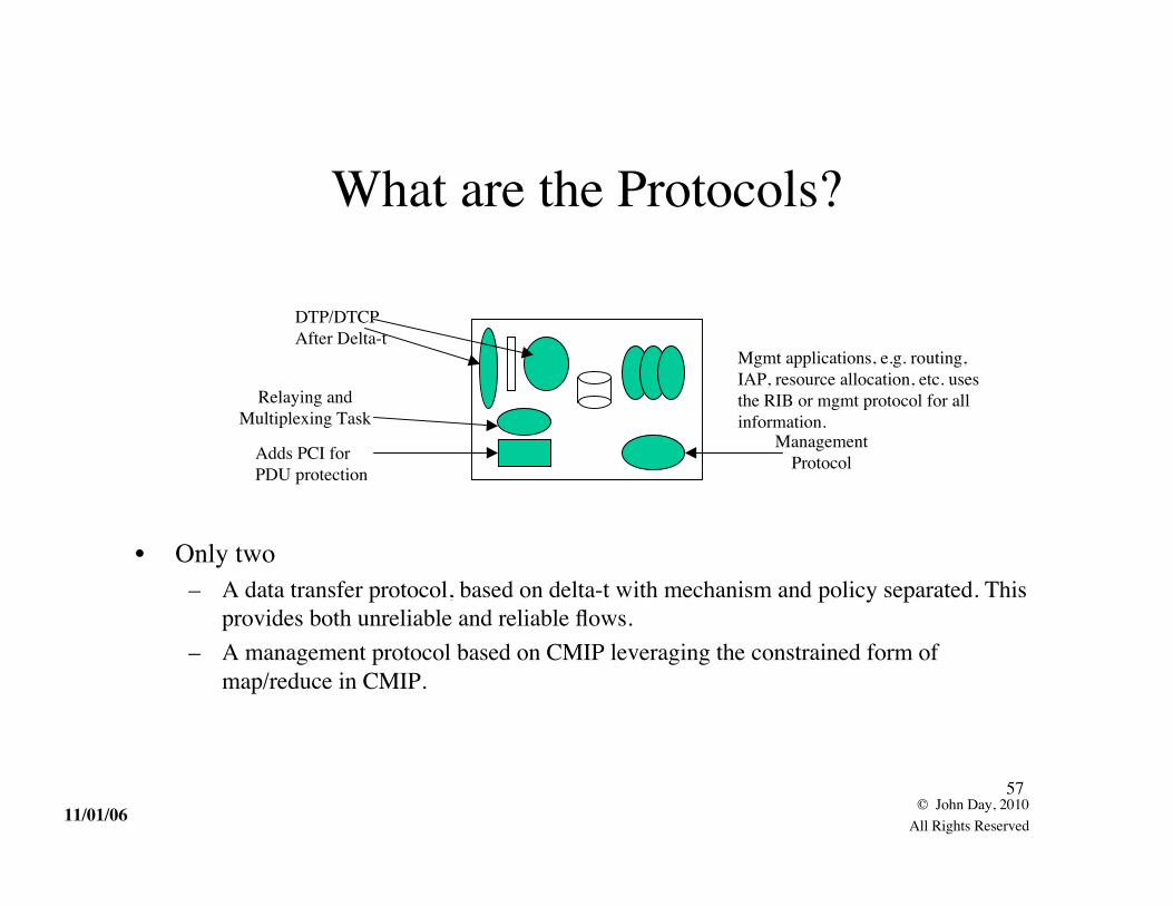
What are the Protocols?
• Only two– A data transfer protocol, based on delta-t with mechanism and policy separated. This
provides both unreliable and reliable flows.– A management protocol based on CMIP leveraging the constrained form of
map/reduce in CMIP.
Relaying andMultiplexing Task
Adds PCI forPDU protection
ManagementProtocol
Mgmt applications, e.g. routing,IAP, resource allocation, etc. usesthe RIB or mgmt protocol for allinformation.
DTP/DTCPAfter Delta-t

11/01/0658
© John Day, 2010All Rights Reserved
The Application Entitiesof an IPC Process
• The Application Process of an IPC Process is management.– Flow Allocator manages flows, finds the destination and does access control, manages
the binding of connection-endpoint-ids to port-ids.– Data Transfer AE is the error and flow control protocol– RMT AE consists of the relaying and multiplexing task and SDU Protection– RIB Daemon maintains the local RIB information.– CAP AEs are management flows with other members of the DIF and NMS
Data Transfer AE(one per flow)
Flow Allocator(one per IPC
Proc)
RMT AE(one per IPC
Proc)
CAP AEs
IPC Process(Management)
RIB Daemon

11/01/0659
© John Day, 2010All Rights Reserved
But Wait a Minute!
• If a Layer is a Distributed Application that Does IPC,• What is a Distributed Application?
– a Distributed Application Facility (DAF).
• Good Question!
• What are the elements that would be common to distributedapplications that don’t do manage IPC.
• Notice that a DIF is primarily a DAF that manages IPC.

11/01/0660
© John Day, 2010All Rights Reserved
Distributed Application Facility
• A DAF consists of SDU protection, the Common Application Protocol (CMIP+ ACSE), an Object Information Base, and the OIB Daemon.
• The transition from a DIF to a DAF is a transition from an IPC model to aprogramming language model.
– The task of the OIB Daemon is to populate the OIB with whatever the Applicationneeds on whatever schedule it needs it: a sort of “schema pager”
SDU Protection
ObjectInformation
Base
CommonApplication
Protocol
OIB Daemon
The Application

11/01/0661
© John Day, 2010All Rights Reserved
Common Distributed Application Protocol
• ACSE is the common protocol for establishing application connections. It ensurethat there is a known first exchange.
– ACSE was defined to be used recursively and has hooks for. . .• An authentication module is policy of whatever strength required.• CMIP provides the minimal six operations and a basic object-oriented
functionality (scope and filter).– Would other programming paradigms lead to different functions?
ACSE Authentication CMIP

11/01/0662
© John Day, 2010All Rights Reserved
Only Three Kinds of Systems
• Middleboxes? We don’t need no stinking middleboxes!• NATs: either no where or everywhere,
• NATs only break broken architectures• The Architecture may have more layers, but no box need
have more than the usual complement.– Hosts may have more layers, depending on what they do.
Hosts
InteriorRouters
BorderRouters

11/01/0663
© John Day, 2010All Rights Reserved
Hosts Might Have More DIFs
“Link”{ Layers
Local App
Traditional NetworkTransport Layers
Mail Appl
Simple App
VPN
TransactionProcessingApplication
(over a VPN)
Note that the VPN could occur onelayer lower as well or even lower,but then it would just be a PN.
User Applications use whatever layer has sufficientscope to communicate with their apposite.
11/01/0664
© John Day, 2010All Rights Reserved
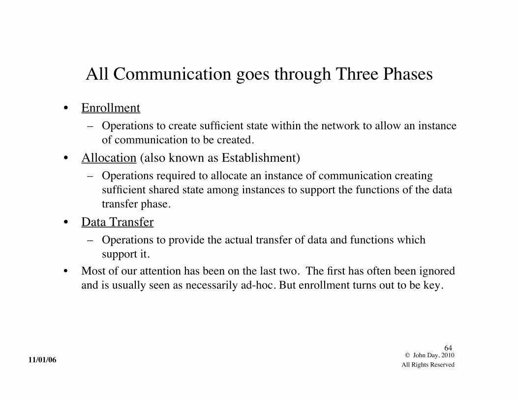
All Communication goes through Three Phases
• Enrollment– Operations to create sufficient state within the network to allow an instance
of communication to be created.• Allocation (also known as Establishment)
– Operations required to allocate an instance of communication creatingsufficient shared state among instances to support the functions of the datatransfer phase.
• Data Transfer– Operations to provide the actual transfer of data and functions which
support it.• Most of our attention has been on the last two. The first has often been ignored
and is usually seen as necessarily ad-hoc. But enrollment turns out to be key.

11/01/0665
© John Day, 2010All Rights Reserved
How Does It Work? Joining a Layer
• Nothing more than Applications establishing communication (for management)– Authenticating that A is a valid member of the (N)-DIF– Initializing it with the current information on the DIF– Assigning it a synonym to facilitate finding IPC Processes in the DIF, i.e. an address
(N-1)-DIF
(N)-DIF
A

11/01/0666
© John Day, 2010All Rights Reserved
How Does It Work?Establishing Communication
• Simple: do what IPC tells us to do.– A asks IPC to allocate comm resources to B– Determine that B is not local to A use search rules to find B– Keep looking until we find an entry for it.– Then go see if it is really there and whether we have access.– Then tell A the result.
• This has multiple advantages.– We know it is really there.– We can enforce access control– We can return B’s policy and port-id choices– If B’s has moved, we find out and keep searching
A BAhh, here it is!

11/01/0667
© John Day, 2010All Rights Reserved
How Does It Work?“Congestion Control”
• Congestion Control in TCP was always known to be a stop-gap.• A DIF always has the potential for the full capability of functions.• Do flow control (without retransmissions) between intermediate points.
– Better congestion control, really flow control– Allocate different resources to different e-malls.– Allows provider much more effective management of resources.– Provides means to throttle flows being used for denial of service attacks– All of these places? Doubtful. Research topic..

11/01/0668
© John Day, 2010All Rights Reserved
How Does It Work?The Internet and ISPs
• ISPs have as many layers as they need to best manage their resources.
Backbone
Regionals
Metros

11/01/0669
© John Day, 2010All Rights Reserved
How Does It Work?The Internet and ISPs
• The Internet floats on top of ISPs, a “e-mall.”– One in the seedy part of town, but an “e-mall”– Not the only emall and not one you always have to be connected to.
Public Internet
ISP 1 ISP 2 ISP 3

11/01/0670
© John Day, 2010All Rights Reserved
How Does It Work?The Internet and ISPs
• But there does not need to be ONE e-mall.– You mean!
• Yes, it is really an INTERnet!
Public Internet
ISP 1 ISP 2 ISP 3
Internet Rodeo Drive
Utility SCADAMy NetFacebook Boutique
Internet Mall of America

11/01/0671
© John Day, 2010All Rights Reserved
How Does It Work?The User’s Perspective
In this case, one host on the local network chooses to joinone of the available e-malls.
e-common DIFs
Provider Network
Local CustomerNetwork
Peering DIF
A Customer Network has a border router that makes severale-malls available. A choice can be made whether the entirelocal network joins, a single host or a single application.
e-common DIFs
Provider Network
Local CustomerNetwork
Peering DIF

11/01/0672
© John Day, 2010All Rights Reserved
How Does It Work?Security
• Security by isolation, (not obscurity)
• Hosts can not address any element of the ISP.• No user hacker can compromise ISP assets.
• Unless ISP is physically compromised.
ISP Hosts and ISPs do not share DIFS.(ISP may have more layers

11/01/0673
© John Day, 2010All Rights Reserved
How Does It Work?Security
• The DIF is a securable container. DIF is secured not each component separately.• Application only knows Destination Application name and its local port.• The layer ensures that Source has access to the Destination
– Application must ensure Destination is who it purports to be.• All members of the layer are authenticated within policy.• Minimal trust: Only that the lower layer will deliver something to someone.• PDU Protection can provide protection from eavesdropping, etc.
– Complete architecture does not require a security connection, a la IPsec.
Port:=Allocate(Dest-Appl, params)
Access ControlExercised

11/01/0674
© John Day, 2010All Rights Reserved
How Does It Work?Security
• A Hacker in the Public Internet cannot connect to an Application in anotherDIF without either joining the DIF, or creating a new DIF spanning both.Either requires authentication and access control.
– Non-IPC applications that can access two DIFs are a potential security problem.
Public Internet
ISP 1 ISP 2 ISP 3
Internet Rodeo Drive
Utility SCADAMy NetFacebook Boutique
Internet Mall of America

11/01/0675
© John Day, 2010All Rights Reserved
There More to Come
• Next Naming and Addressing– It turns out to be quite straightforward and simple.
• Looking at the Internals in a bit more detail– What does DTP and DTCP really look like?– What does the Flow Allocator and the RIB Daemon do?– What goes into defining a DIF?
• A Claim: One will not find a structure that is both as rich and assimple as this that is not equivalent to it. Prove me wrong! ;-)
May 5, 10 . 1
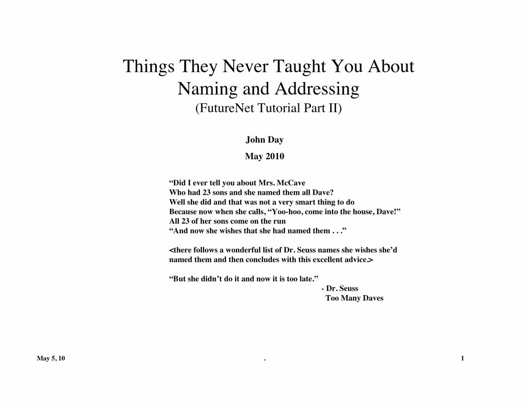
Things They Never Taught You AboutNaming and Addressing
(FutureNet Tutorial Part II)
“Did I ever tell you about Mrs. McCaveWho had 23 sons and she named them all Dave?Well she did and that was not a very smart thing to doBecause now when she calls, “Yoo-hoo, come into the house, Dave!”All 23 of her sons come on the run“And now she wishes that she had named them . . .”
<there follows a wonderful list of Dr. Seuss names she wishes she’dnamed them and then concludes with this excellent advice.>
“But she didn’t do it and now it is too late.” - Dr. Seuss Too Many Daves
John Day
May 2010

May 5, 10 . 2
Going Back to Fundamentals
• Develop the concepts moving from more fundamental tomore specific.– Fundamentals of Naming– Naming in Computing Systems– Naming for Communicating Processes– Naming for IPC

May 5, 10 . 3
Names and Name Spaces• A name space, NS, is a set {N} of names from which all names for a
given collection of objects are taken. A name from a given name spacemay be bound to one and only one object at a time.
• A name is a unique string, N, in some alphabet, A, that unambiguouslydenotes some object or denotes a statement in some language, L. Thestatements in L are constructed using the alphabet, A.
• A function, MNS, which defines the class of objects, M, that may benamed with elements of NS. This is referred to as the scope of the namespace (see below). This may refer to actual objects or the potential for objects to becreated.
• A function, FMNS, that defines the mapping of elements of NS toelements of M. This function is one-to-one and onto and is called abinding.

May 5, 10 . 4
Operations on Names
• Assignment, allocates a name in a name space, essentially marks it inuse. Deassignment, removes it from use. Assignment makes namesavailable to be bound. This allows certain portions of a name space tobe “reserved,” not available for binding.
• Binding, maps a name to an object. Once bound, any reference to thename accesses the object. Unbinding breaks the binding. Onceunbound, any reference will not access any object.– An object ceases to exist when the last name referring to it is unbound.
• Saltzer [1977] defines “resolve” as in “resolving a name” as “to locatean object in a particular context, given its name.”– An object cannot be identified without locating it nor located without
identifying it.

May 5, 10 . 5
Types of Names• Objects may be assigned more than one name. These are called
synonyms or aliases.– Objects that may have more than one name, the names are unambiguous.– Objects that must have only one name, the names are unique.
• Names may also denote sets of names. Associated with the set is arule that determines which names are returned when the name of theset is resolved. In networking,– A rule that returned all members has been called multicast.– A rule that returned one member has been called anycast.– We will refer to all forms as whatevercast!
• Synonyms or names of sets may be taken from the same or differentname spaces.– The name of an object is the name of a set of one element.

May 5, 10 . 6
Resolving Names
• There are 2.5 means to resolve names:– Exhaustive Search– The name provides hints to narrow the search.
• The “half” is indirection:– The name or part of the name points to an object that points to a name.
• Hierarchy is the most common form of embedding hints in a name.– Hierarchy imposes a topological structure on the name space, which
constrains the names that can be assigned to an object.– There may be search rules for how to utilize the “hints.”
• Every thing up to this point is applicable to all naming in computingsystems.

May 5, 10 . 7
Address Spaces in Operating Systems(From my OS Course)
An name space is defined as a set of identifiers with a given scope.An address space is a location-dependent name space.In Operating Systems, we have found a need for 3 such independent spaces.Virtually all uses of names in computing are for locating.
Application Name Space
Logical Name Space
Physical Name Space
Human use, relatively constant,not at all tied to the hardware,i.e. location-independent
Location Dependent but HardwareIndependent; Creates a logical addressspace larger than the physical memory;Allows processes to be re-locatable.
Location-Dependent andHardware Dependent

May 5, 10 . 8
The Root of Internet Addressing Problems
IMP
56K Trunk
56K Trunk
56K Trunk
56K Trunk
HostHost
Host Host
A host’s address was its IMP Port Number. It was the common approach at the time.The ARPANet was first. Everyone else afterwards fixed the problem, except the Internet.
So What is the Fix?

May 5, 10 . 9
• Shoch [1978] put it eloquently:– Application names indicate what is to accessed– Node addresses indicate where it is– Routes tell you how to get there.
• In 1982, Jerry Saltzer published the “other” major paper on addressing.– Wrote down the OS view of network addressing:
• Saltzer, Jerry. “On the Naming and Binding of Network Destinations” in Local ComputerNetworks, edited by P. Ravasio et al. P North-Holland Publishing Company, pp 311-317,1982, republished as RFC 1498.
– Application names that were location independent– Node addresses that were location dependent (the logical address)– Point of attachment addresses that were route-dependent (the physical address)– Routes which were actually a sequence of point of attachment addresses– And the three mappings between them.
• Saltzer works through the problem in somewhat more detail.– Colored by the hardware of the time and the OS perspective.
OS’s Were the Guide

May 5, 10 . 10
Modeling Saltzer
SystemLayer
• A Logical Model of a Network System– Naming the binding between a (N)- and (N-1)-PM is equivalent to naming
the (N-1)-PM. Need to do one or the other.• Saltzer seems to favor naming PMs.
– Since ultimately we must name the application and we know it isn’t abinding, naming PMs makes sense.
Application Name
NodeAddress
Point of AttachmentAddress

May 5, 10 . 11
Saltzer’s View of Networks• Application names map to node addresses.• Node addresses map to points of attachment addresses.• Routes are sequences of points of attachments.
– Just as in an operating system.– But networks are more general than operating systems.
Application Name
NodeAddress
Point of AttachmentAddress

May 5, 10 . 12
But Saltzer Missed a Case
• There can be More than One path to the Next Hop.– This case does not occur in computing systems. There is only one path
from the CPU to memory.• Must route on the Node addresses, not the point of attachments
Application Name
NodeAddress
Point of AttachmentAddress

May 5, 10 . 13
Generalizing Saltzer to Networks of Networks• Directory maintains the mapping between Application-Names and the node
addresses of all Applications reachable without an application relay.• Routes are sequences of node addresses used to compute the next hop.• Node to point of attachment mapping for all nearest neighbors to choose path
to next hop. (Saltzer missed this because they hadn’t occurred yet.)• This last mapping and the Directory are the same:
– Mapping of a name in the layer above to a name in the layer below of all nearestneighbors.
Directory
Route
Path
May 5, 10 . 14
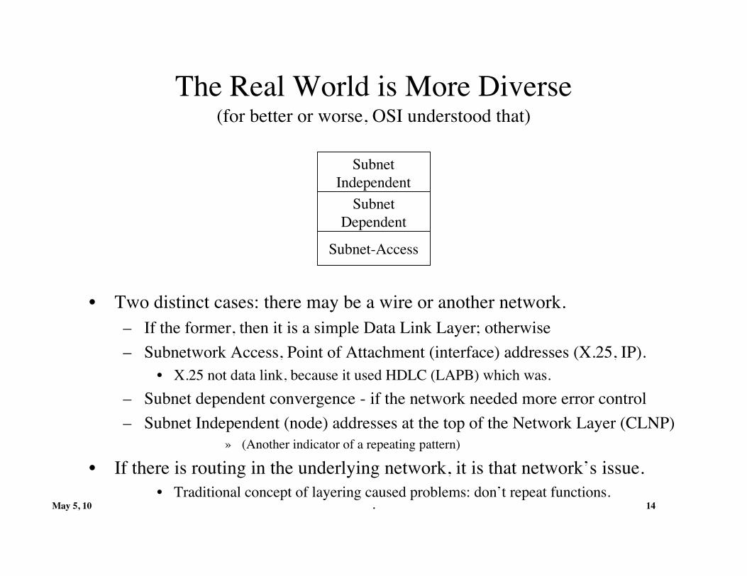
The Real World is More Diverse(for better or worse, OSI understood that)
• Two distinct cases: there may be a wire or another network.– If the former, then it is a simple Data Link Layer; otherwise– Subnetwork Access, Point of Attachment (interface) addresses (X.25, IP).
• X.25 not data link, because it used HDLC (LAPB) which was.– Subnet dependent convergence - if the network needed more error control– Subnet Independent (node) addresses at the top of the Network Layer (CLNP)
» (Another indicator of a repeating pattern)
• If there is routing in the underlying network, it is that network’s issue.• Traditional concept of layering caused problems: don’t repeat functions.
Subnet-Access
SubnetDependent
SubnetIndependent

May 5, 10 . 15
To RecapMappings between Name Spaces
• Mapping between application names and node addresses: Directory.– Allows for applications moving to different systems or systems moving.
• Sequence of node addresses: Routes.– Node address space is a logical abstraction of point of attachment address
spaces.• Node address space must be de-coupled from the point of attachment address
space(s).• Any form that concatenates a local (N)-layer identifier to an (N-1)-address to
create an (N)-address will make the node address space route dependent.– From this we determine the next hop.
• Mapping of node addresses to point of attachment addresses: Path.– A node needs this mapping for itself and all nearest neighbors.– Point of attachment addresses distinguish multiple paths to the next node (hop).– Note that this is the same as the Directory.
• And it repeats: Node and Point of Attachment are relative, not absolutes.

May 5, 10 . 16
The Fundamental Flaw in theIP Architecture
• Given what we have seen already we can see the mistake,– By following Saltzer and routing on the interface, the Internet
architecture assumes there is a point-to-point line under IP.• An Internet Protocol should have networks under it.• A Network is a “wire with multiple ends”, i.e. requires addresses.
– Points of attachment– Where are these in the architecture?
• By routing on the interface,– IP is a Network Protocol not an Internet Protocol– After IPng’s refusal to name the node, there has been a search for a
workaround. There is none. Loc/id split is simply the last attempt. It isin a very real sense post-IPng trauma.

May 5, 10 . 17
Applying Results to Real Architectures: The Internet(This is a Network Architecture)
• The most striking feature is that half of the addressing architecture is missing.– No wonder there are addressing problems.– The only identifier we have for anything is the IP address.
• There are no node addresses and no application names.– And the point of attachment is named twice!– If this is an Internet Protocol, where are the Network Addresses?– Domain Names are synonyms for IP addresses. URLs are pathnames through the
stack and location dependent.
MAC Address
IP Address
Socket (local)
ApplicationApplication
Name
Node Address
Point of AttachmentAddress
As if your computer worked only with absolute memory addresses.

May 5, 10 . 18
What Does RINA Tell Us?
• If networking is a distributed application that doesIPC, we should start there.

May 5, 10 . 19
Communicating Processes
• Application Processes exist to do work. They communicate to do thatwork. Communicating is not (usually) their primary raison d’etre.
• So how do applications relate to communication?– Communicating applications share state on some things.– They can’t be unaware of communicating.– So what is the nature of the relation between the communication
mechanism and the application process?• Now we need the Application Process/Application Entity distinction

May 5, 10 . 20
Applications and Communication
• The Application-Entity (AE) is that part of the application concernedwith communication, i.e. shared state with its peer.
• The rest of the Application Process is concerned with the reason forthe application in the first place.
• An Application Process may have multiple AEs, they assumed, fordifferent application protocols.– An HTTP library linked into a web browser is an AE; FTP is another.
ApplicationProcess
Application-Entities

May 5, 10 . 21
Application Naming
• Application-process names (APN) are globally unambiguous and location-independent,but system-dependent.
– They may have synonyms of less scope from the same or different name space.– There may be multiple instances of the process in the same system.
• APN-instance-identifiers are unambiguous within the scope of the Application Process.
• Application-entity-identifiers are unambiguous within the application process.– There may be more than one Application-entity (AE) in a process.
• Unambiguous within the scope of the Application Process.– There may be more than one instance of each type of Application-Entity.
• AE-instance-identifiers are unambiguous within the scope of the AE.
• Distributed Application Name is the name of a set of application processes and system-independent.
• Few applications need all of these but a complete theory requires all of them.
ApplicationProcess
Application-Entities

May 5, 10 . 22
What Good is All This?
• Many capabilities not possible today or that require specific protocolsare a consequence of naming and enabled by a complete architecture.– Handing off a connection from one system to another;– The need to pass IP addresses among applications is avoided;– Opening multiple connections with different “protocols” to the same
instance of an application process.– Connecting to an existing “conference” call, etc.
ApplicationProcess
Application-Entities
May 5, 10 . 23
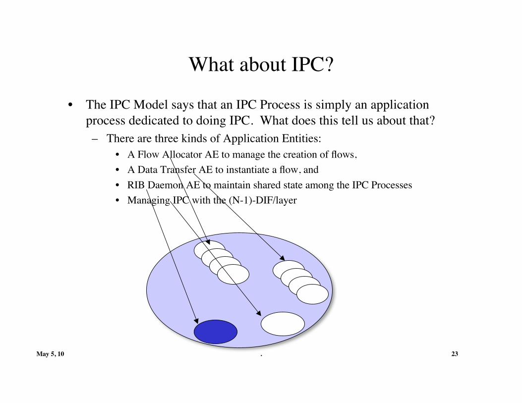
What about IPC?
• The IPC Model says that an IPC Process is simply an applicationprocess dedicated to doing IPC. What does this tell us about that?– There are three kinds of Application Entities:
• A Flow Allocator AE to manage the creation of flows,• A Data Transfer AE to instantiate a flow, and• RIB Daemon AE to maintain shared state among the IPC Processes• Managing IPC with the (N-1)-DIF/layer

May 5, 10 . 24
What is the “Application” of an IPC Process?
• What is the main work of an IPC Process? Management!– Not, Data transfer.
• Managing the IPC within the Layer.– Resource Allocation– Maintaining a Resource Information Base– Routing– Security Management
Relaying/MuxingPDU Protection
DataTransfer
AllocationMngmt
UpdateDaemon

May 5, 10 . 25
What about IPC Naming?• An IPC Process has an Application Process Name, give it a synonym of
scope limited to the layer, and if structured to facilitate forwarding.• Commonly called an address
• There are three local identifiers:– A Flow Allocator AE Instance Identifier,
• Commonly called a port-id– A Data Transfer AE Instance Identifier, and
• Commonly called a connection-endpoint-identifier– RIB Daemon AE to maintain shared state among the IPC Processes
• Traditionally routing update.
• This coupled with delta-t has major implications (later).
AddressCEP-ids
Flows
Port-ids
bindings

May 5, 10 . 26
Names for IPC
• An Address is a synonym for the IPC Process, with scope restricted tothe layer and structured to facilitate forwarding within the layer/DIF.– A port-id is the handle returned to the calling application to refer to this
instance of communication, unique within its AE.– A connection-endpoint-id (CEP-id) identifies the shared state of one end
of a flow/connection, unique within its AE.• A connection-id identifies flows between the same two IPC Processes,
formed by concatenating CEP-ids, unique within the pair• Distributed Application Name is globally unambiguous name for the
set of all Application Processes in a Distributed Application, e.g. DIF.
Port-ids
CEP-ids
AddressIPC Process

May 5, 10 . 27
To Summarize
• All identifiers except address and connection-id are local to the IPCProcess.– Scope of the address is the Layer.– Scope of the connection-id is the participants in the connection.
• None has more scope than it needs.
AE-identifierIPC Process (unambiguous)DIF Management Updates
Concatentation of data-transfer-AE-instance-identifiers
Src/Dest Data Transfer AE(unique)
Connection-id
Data Transfer AE Instance-Identifier
Data Transfer AE (unique)Connection-endpoint-identifier
Allocation AE-Instance-Identifier
Allocation AE (unique)Port-id
Synonym for IPC Process’Application Process Name
Layer (unambiguous)Address
Application Process Name“Global” (unambiguous)Application Process Name
Application TermScopeCommon Term

May 5, 10 . 28
Principles of Naming and Addressing: I
• Application names indicate what, not where.– Hence, names are organized to put similar “whats” near each other.– So what “whats” do we use?
• There is no single answer. Depends on the purpose and the importance of lookup performance generally in a distributed directory.
– The Scope of an Application Name Space is defined by the chain ofdatabases pointed to by the Directory Forwarding Table.
• Different Application Name Spaces may name the same objects.– It is here that the concepts of query and name merge
• Some schemes will produce multiple results; some a unique result• Given the move to greater granularity more schemes will be useful in keeping
them tractable and useful.– The only requirement for IPC is that some collection of synonyms be
associated with an application process and their mapping to the directoryare made known.

May 5, 10 . 29
Principles of Naming and Addressing: II• Addresses indicate where – Not quite
– Within a DIF, the “what” of interest is “forwarding.” Synonyms areassigned to facilitate forwarding, call it a forwarding-id or f-id.
– If the DIF has a sufficiently large number of members (or maybe if itdoesn’t) to make F-ids more useful.
• They are structured to reflect which elements are near each other for someconcept of near. This is an address.
• This is an “address” in the sense of its normal usage, expressing “where”without indicating “how to get there.”
– An address is an synonym for an IPC Process whose scope is the DIF andstructured to be useful within the layer.
– “where” is just one kind of “what”
– Application Names and Addresses are simply two different means forlocating an object in different contexts. In this case, the object is an IPCProcess.

May 5, 10 . 30
Principles of Naming and Addressing: III
• A F-id (or address) is only unambiguous within the scope of a layer.– And no more, otherwise this leads to overloading the semantics of the
address and leads to problems– MAC addresses are 3 times longer than they need to be.
• Routes are sequences of (node) addresses.– Source routing is a “male thing,” not willing to stop and ask directions.
• The relation of node and point of attachment is relative and henceirrelevant.
• A node address is an (N)-F-id;• A point of attachment address is an (N-1)-F-id.
– A layer routes on its address. A node address routes this layer’s address,the point of attachment address is the address of the node in the layerbelow and is routed by the layer below, not by this layer.

May 5, 10 . 31
Principles of Naming and Addressing: IV
• Since the address is structured to facilitate its use within the layer, it must beassigned by the layer.– Only the layer knows how to make the synonym useful.
• Any addresses assigned by anyone else are not addresses.• Names of systems are useful management functions, but not for forwarding.
– Names of Hosts are distinct and not related to addressing.• An address should not be constructed by concatenating an identifier in this
layer with one from the lower layer, i.e. don’t embed MAC addresses in IP addresses.
– Why? This construction is called a pathname, hence it is route-dependent!– Addresses in adjacent layers should be completely independent.– Hierarchical address assignment within a layer organizes addresses in this layer, not
the layer below.– Each layer is a level of indirection.

May 5, 10 . 32
Implications of the Naming Model: I
• Recursion either reduces the number of routes or shortens them.
Backbone
Regionals
Metros

May 5, 10 . 33
Implications of the Naming Model: III
• For the Internet O((6r)2 where r is the number of routers in the network.
Non-topological T opological Metros-DIF 3 O ( ( 2 D n)2 ) O ( ( D m)2 ) where n is the number of hosts
and m is the number of hosts and border routers on a single subnet.
Regionals-DIF 2 O((2Dn2)2 ) O ( ( D m2)2 ) where n2 is the number of border routers around the outside and m2 is number of border routers at this level on a single subnet.
Backbone-DIF 1 O((2Dn1)2 ) O ( ( 2 D n1)2 ) where n1 is the number of border routers on the backbone. Note that m << n.
The Complexity of Routing

May 5, 10 . 34
Naming Implications of the Model: II
• Multihoming is a consequence of the structure.– Simply a layer having more than one (N-1) binding.
• Since we are routing in this layer, there is no big deal– By routing on the address, the destination address is the destination
regardless of which interface the PDU arrived on. It is route-independent.– With recursion, no scaling problems, no LISP, no LISP support protocols.
An Internet
Provider Independent
Provider dependent
Application

May 5, 10 . 35
Naming Implications of the Model: III
• Mobility is a consequence of multihoming.– Merely acquiring new (N-1)-addresses to use or losing others.
• No different than so-called “static” case, just more frequent.– (N)-address may change either by joining a different DIF
• Joining another DIF is simply acquiring another point of attachment, another potential path.– or if its topological significance changes.
• Assigning a new address is simply creating adding an additional synonum. Protocolprocessing is unaffected by the changes.
An Internet
Provider Independent
Provider dependent
Application

May 5, 10 . 36
Naming Implications of the Model: IV
• How to Change the Address of a member of the DIF:– Assign the IPC Process a new synonym from the address space;– Senders use the new (N)-address as source in all active flows– Receivers record the source address of all incoming PDUs as the current address.– Advertise routes to the new address, begin to deprecate the old address– After a few routing updates, the old address simply disappears.
• Changing addresses is just another name to route to. That two go to the sameplace is mere coincidence.
• PDU Processing is unaffected by the change.
An Internet
Provider Independent
Provider dependent
Application

May 5, 10 . 37
Implications of the Model: VChoosing a Layer
• In building the IPC Model, the first time we had multiple DIFs (data linklayers in that case to choose from), we found we needed a task to figureout which DIF to use.
IAPDir
MuxFlowMgr
– User didn’t have to see all of the wires– But the User shouldn’t have to see all of the “Nets”
either.
• This not only generalizes but has major implications.

May 5, 10 . 38
An Inter-Net Directory?
• Inter-DIF Manager determines via what DIFs applications are available.– If this system is a not member, it either joins the DIF as before– or creates a new one.
• Which Implies that the largest address space has to be only large enoughfor the largest e-mall.• Given the structure, 32 or 48 bits is probably more than enough.
• You mean?• Right. IPv6 was a waste of time . . .• Twice.
Inter-DIFMngr

May 5, 10 . 39
So a Global Address Space is Not Required butNeither is a Global Application Name Space
Inter-DIFDirectory
To PeersIn Oher DIFs
Actually one could still have distinct names spaces within aDIFs (synonyms) with its own directory database.
• Not all names need be in one Global Directory.• Coexisting application name spaces and directory of distributed
databases are not only possible, but useful.• Needless to say, a global name space can be useful, but not a
requirement imposed by the architecture.• The scope of the name space is defined by the chain of databases that
point to each other.

May 5, 10 . 40
Multicast and Anycast are Simpler Too
• Generalized to Whatevercast:– A set and a rule that returns as many members of the set that satisfy the
rule.• Unicast becomes a degenerate case of whatevercast.
– Forwarding table entry maps Destination Address to a list of next hops.For unicast, the list has one element.
• Primarily handled by hosts or border routers, where all whatevercasttraffic is either:
• On this subnet (only do spanning tree within subnet if there is a lot) or• Transit to another subnet, (both cases degenerate to point-to-point).
• So we see Whatevercast devolves into Unicast.

May 5, 10 . 41
Multicast and Anycast are Simpler Too
• Information in topological addresses imply an approximate spanningtree, which can be used to identify the border routers. Thjus, in mostcases obviating the need for a separate spanning tree (multicast)routing algorithm.
• And also making it straightforward to multiplex whatevercasts withcommon sub-trees which will allow even greater efficiency.– Note that the common sub-trees do not have to be strict sub-trees but
simply have a reasonable degree of commonality to be worthwhile.

May 5, 10 . 42
Next:Digging into the Details!
How Does it Really Work?

10 May 10 1© John Day, 2010All Rights Reserved
The Nuts and Bolts of RINAFutureNet Tutorial Part III
John DayMay 2010
10 May 10 2© John Day, 2010All Rights Reserved
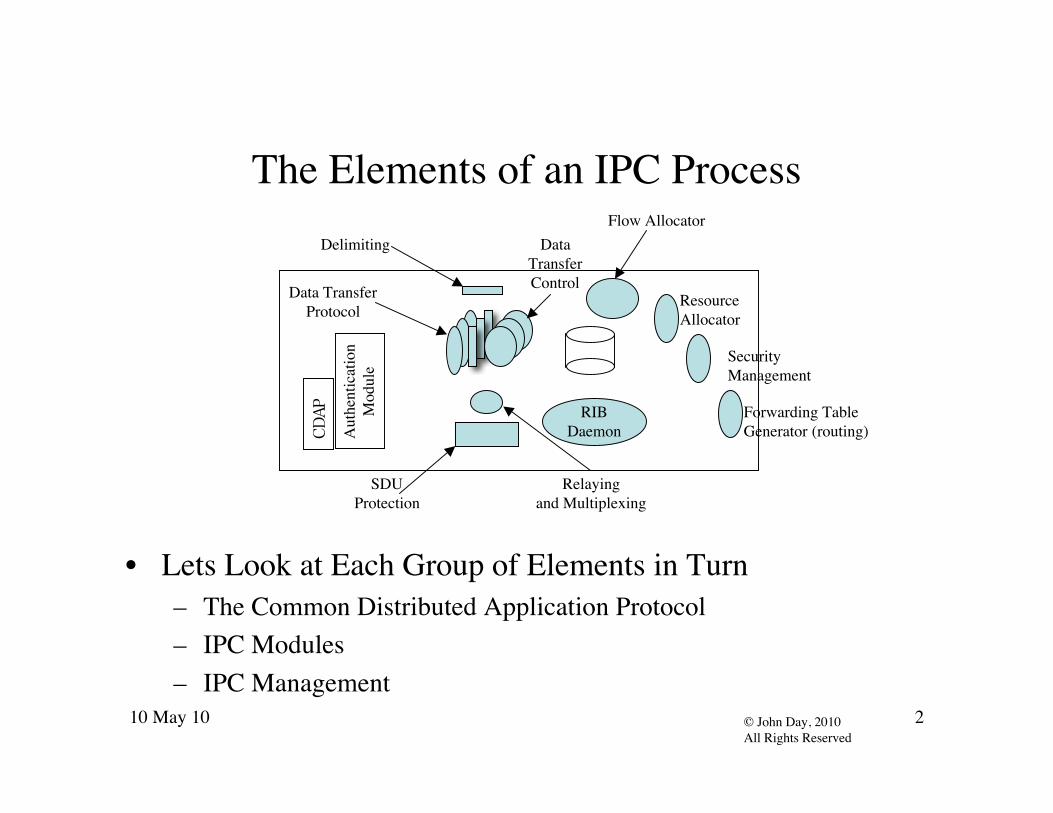
The Elements of an IPC Process
• Lets Look at Each Group of Elements in Turn– The Common Distributed Application Protocol– IPC Modules– IPC Management
CDAP
Aut
hent
icat
ion
Mod
ule
RIBDaemon
Delimiting
Data TransferProtocol
DataTransferControl
Relayingand Multiplexing
SDUProtection
Forwarding TableGenerator (routing)
Flow Allocator
SecurityManagement
ResourceAllocator

10 May 10 3© John Day, 2010All Rights Reserved
Common Distributed Application Protocol
• The only application protocol that is required– DAFs may use others for backward compatibility– Used in DIFs for all non-data transfer communication
• Three components:– Application Connection Establishment– Authentication (policy)– CMIP-like operations
• Distinct flows allow operations on specific sets of objects
CDAP
Aut
hent
icat
ion
Mod
ule

10 May 10 4© John Day, 2010All Rights Reserved
CDAP:Application Connection Establishment
• Request/Response that carries:– Source and Destination Application-Process names and
Application-Entity-identifiers (including instances) as necessary.– Application-context definition (object set available)– Syntax negotiation
ACRQ
ACRsp

10 May 10 5© John Day, 2010All Rights Reserved
CDAP• Why CMIP? It’s a management protocol.
– Not really, it is a distributed object-oriented intermediate language– That does create/delete, read/write (get/put), action (start/stop)– With OO-support in Scope and Filter:
• Scope selects the base object alone, the nth level of the base object,the base object and all its subordinates to and including the nth level,or the base object and all its subordinates.
– This can be quite powerful in minimizing traffic.• Filter is an expression of assertions grouped using AND, OR, and
NOT to determine equality, ordering, presence, or set comparison.– Extensions to scope and filter should be considered.
• CMIP does everything required and nothing more.

10 May 10 6© John Day, 2010All Rights Reserved
Why Not SNMP?
• Too complex.– Implementation is larger than CMIP.
• Not object-oriented, no leverage.• Too many restrictions that contribute to complexity.
– Can’t retrieve entire tables– Can’t modify multiple attributes in a single operation.– Can’t, Can’t, Can’t.– It was a good protocol for the mid-80s, but was obsolete by the
time it was proposed.
10 May 10 7© John Day, 2010All Rights Reserved
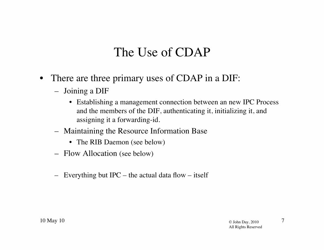
The Use of CDAP
• There are three primary uses of CDAP in a DIF:– Joining a DIF
• Establishing a management connection between an new IPC Processand the members of the DIF, authenticating it, initializing it, andassigning it a forwarding-id.
– Maintaining the Resource Information Base• The RIB Daemon (see below)
– Flow Allocation (see below)
– Everything but IPC – the actual data flow – itself

10 May 10 8© John Day, 2010All Rights Reserved
The IPC Modules
• There are Five Modules:– Delimiting– The Error and Flow Control Protocol consisting of:
• Data Transfer (Sequencing/Fragmentation)• Data Transfer Control (Flow control and rexmsn control)
– Relaying and Multiplexing– SDU Protection
Delimiting
Data TransferProtocol
DataTransferControl
Relayingand Multiplexing
SDUProtection

10 May 10 9© John Day, 2010All Rights Reserved
Delimiting
• This Module delimits SDUs to ensure that the servicemaintains the identity on delivery.– IPC may fragment or combine SDUs but will deliver same SDUs
to the destination.• External and Internal Delimiting are possible.• This module is entirely policy.
– For a flow that appears to be streaming, the entire flow is a singleSDU and early delivery is allowed.

10 May 10 10© John Day, 2010All Rights Reserved
SDU Protection
• SDU Protection is also entirely policy and may include:– Data Corruption Protection (CRCs or FECs)– Time to Live– Integrity and Confidentiality (encryption)
• Below we will explore why the heavy duty mechanisms of IPsec likesolutions are not required.
– Compression - not really protection but this is the right place for it
10 May 10 11© John Day, 2010All Rights Reserved
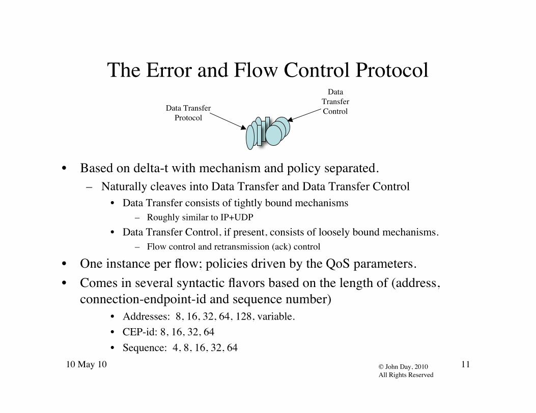
The Error and Flow Control Protocol
• Based on delta-t with mechanism and policy separated.– Naturally cleaves into Data Transfer and Data Transfer Control
• Data Transfer consists of tightly bound mechanisms– Roughly similar to IP+UDP
• Data Transfer Control, if present, consists of loosely bound mechanisms.– Flow control and retransmission (ack) control
• One instance per flow; policies driven by the QoS parameters.• Comes in several syntactic flavors based on the length of (address,
connection-endpoint-id and sequence number)• Addresses: 8, 16, 32, 64, 128, variable.• CEP-id: 8, 16, 32, 64• Sequence: 4, 8, 16, 32, 64
Data TransferProtocol
DataTransferControl
10 May 10 12© John Day, 2010All Rights Reserved
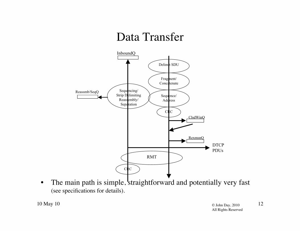
Data Transfer
• The main path is simple, straightforward and potentially very fast(see specifications for details).
RMT
CRC
Sequencing/Strip Delimiting
Reassembly/Separation
Reassmb/SeqQ
InboundQ
CRC
Delimit SDU
Fragment/Concatenate
Sequence/Address
RexmsnQ
ClsdWinQ
DTCPPDUs

10 May 10 13© John Day, 2010All Rights Reserved
Data Transfer PDU• Version: 8 Bit• Destination-Address: Addr-Length• Source-Address: Addr-Length• Flow-id: Struct
– QoS-id: 8 Bit– Destination-CEP-id: Port-id-Length– Source-CEP-id: Port-id-length
• PDUType: 8 bits• Flags: 8 bits• PDU-Length: LengthLength• SequenceNumber: SequenceNumberlength• Sequence User-Data{DelimitedSDU* | SDUFrag}

10 May 10 14© John Day, 2010All Rights Reserved
Data Transfer Policies and Parameters• UnknownFlowPolicy – When a PDU arrives for a Data Transfer Flow terminating in
this IPC-Process and there is no active DTSV, this policy consults theResourceAllocator to determine what to do.
• SDUReassemblyTimer Policy – this policy is used when fragments of an SDU arebeing reassembled and all of the fragments to complete the SDU have not arrived.Typical behavior would be to discard all PDUs associated with the SDU beingreassembled.
• SDUGapTimer Policy – this policy is used when the SDUGapTimer expires and PDUshave not been received to a sequence of SDUs with no gaps greater thanMaxGapAllowed. Typically, the action would be to signal an error or abort the flow.
• ClsdWindPolicy - This policy determines what to do if the PDU should not be passed tothe RMT.
• MaxPDUSize – The maximum size in bytes of a PDU in this DIF.• MaxFlowPDUSize – The maximum size in bytes of a PDU on this Flow.• SeqRollOverThres – The value at which a new flow is created and assigned to this
Port-id to support data integrity.• MaxGapAllowed – The maximum gap in SDUs that can be delivered to the (N)-DIF-
port without compromising the requested QoS.

10 May 10 15© John Day, 2010All Rights Reserved
Data Transfer Control
• Control stays out of the main data flow.• This module will not exist for flows that don’t need it.
DTP
RMT
DT-SV
Re-xmsn Q
Xmsn Control Q
DTCPRexmsn
CtlXmsn
Ctl
FlowCtl
Data Flow
Control Flow

10 May 10 16© John Day, 2010All Rights Reserved
Data Transfer Common Control Syntax
Ack/Flow ControlPDUCommon Control PDUPDU TYPE = X’800C’ Ack onlyPDU TYPE = X’800D’ Ack and Flow ControlPDU TYPE = X’8009’ Flow Control onlyAck: Integer(SeqNbrLength)RightWindowEdge:SequenceNbrLengthNewRate: RateLenTimeUnit: TimeLen
Selective Ack PDUCommon Control PDUPDU TYPE = X’8004’Ack/Nack: Integer(SeqNbrLength)Ack/Nack List Length: Integer(8)Ack/Nack List: Sequence(StartingNbr Integer(SeqNbrLength), Ending Integer(SeqNbrLength))
Forced NackPDUCommon Control PDUPDU TYPE = X’8006’Ack/Nack: Integer(SeqNbrLength)Ack/Nack List Length: Integer(8)Ack/Nack List: Sequence(StartingNbrInteger(SeqNbrLength),Ending Integer(SeqNbrLength))
Common Control PDUVersion: 8 BitsDestination-Address: Addr-LengthSource-Address: Addr-LengthFlow-id: Struct
QoS-id: 8 bitsDestination-CEP-id: CEP-id-LengthSource-CEP-id: CEP-id-length
PDUType: 8 bitsFlags: 8 bitsPDU-Length: LengthLengthSequenceNumber: SequenceNumberLength

10 May 10 17© John Day, 2010All Rights Reserved
Data Transfer ControlGeneral Parameters and Policies
• TA – Maximum time an ack is delayed before sending• TG – Maximum time to exhaust retries.• TimeUnit – for rate based flow control, i.e. # of PDUs sent per TimeUnit• FlowInitPolicy – Data Transfer Control initialization policy• SVUpdatePolicy – Updates the State Vector on arrival of a TransferPDU• LostControlPDUPolicy – What to do if a Control PDU is lost?

10 May 10 18© John Day, 2010All Rights Reserved
Data Transfer Control Retransmision Policy
• RTTEstimator Policy – the algorithm for estimating RTT• RetransmissionTimerExpiryPolicy - what to do when a
Retransmission Timer Expires, if the action is not retransmit all PDUswith sequence numbers less than this.
• ReceiverRetransmission Policy - This policy is executed by thereceiver to determine when to positively or negatively ack PDUs.
• SenderAck Policy - provides some discretion on when PDUs may bedeleted from the ReTransmissionQ. This is useful for multicast andsimilar situations where one might want to delay discarding PDUsfrom the retransmission queue.
• SenderAckList Policy - similar to the previous one for selective ack

10 May 10 19© John Day, 2010All Rights Reserved
Data Transfer Control Flow Control Policies
• InitialCredit Policy - sets the initial amount of credit on the flow.• InitialRate Policy - sets the intial sending rate to be allowed on the
flow.• ReceivingFlowControlPolicy - on receipt of a Transfer PDU can
update the flow control allocations.• UpdateCredit Policy – determines how to update the Credit field, i.e.
whether the value is absolute or relative to the sequence number.• FlowControlOverrun Policy - what action to take if the credit or rate
has been exceeded.• ReconcileFlowConflict Policy - when both Credit and Rate based
flow control are in use and they disagree on whether the PM can sendor receive data.

10 May 10 20© John Day, 2010All Rights Reserved
Relaying and Multiplexing Task
• Queues at the top are at least one per QoS Class.• Queues at the bottom are created by the Resource Allocator and may be
related to the number of QoS Classes provided by the lower DIF.
(N-1)-DIF A (N-1)-DIF B
Queues
Ports
PDUs fromEFCP & (N-1)-DIF flows
Forwarding Table

10 May 10 21© John Day, 2010All Rights Reserved
RMT Policies
• RMTQMonitorPolicy – Policy for monitoring the status of the RMTand the QoS being provided by the (N-1)-DIF from data available tothe RMT.
• RMTSchedulingPolicy – Policy determines what flows are mapped towhat RMT queues and how the queues are serviced.
• MaxQPolicy – Policy invoked if a queue reaches its limit.

10 May 10 22© John Day, 2010All Rights Reserved
Flow Allocator
• When Application Process generates an Allocate request, the FlowAllocator creates a flow allocator instance to manage each new flow.
• The Instance is responsible for managing the flow and deallocating theports– DTP/DTCP instances are deleted automatically after 2MPL with no
traffic,• When it is given an Allocate Request it does the following:
Allocate(Dest-Appl-Name, QoS parameters)
FlowAllocator
LocalDir Cache
DirForwarding
Table

10 May 10 23© John Day, 2010All Rights Reserved
Flow AllocatorInput: Allocate Request
1) It inspects the Allocate request and maps the parameters to theappropriate QoS Class and the associated policy set.
2) It instantiates a DTP (and DTCP if necessary) for this flow.3) Checks its local directory cache for the destination application name.
If found, it sends a Create Flow request to destination address;otherwise consults the Dir Forwarding Table and sends the CreateFlow request to the address noted there.
4) When it receives an Create Flow Response it executes an AllocateResponse API call and modifies the state of the DTP as necessary.

10 May 10 24© John Day, 2010All Rights Reserved
Flow AllocatorInput: Create Flow Request
• Inspect local Directory Cache for an entry that indicates where toforward the request.– Each look up hopefully gets it closer to its destination.– The directory forwarding table can create a hierarchy of databases.
• When the lookup finds that the application is here, create a new flowallocator instance to manage this end of the flow, do access control,initiate the application if necessary, and give it the Allocate indication.
• When the Application responds, if positive, create the localDTP/DTCP instances, allocate local ports: if negative discard the flowallocator instance; Regardless send the create flow response to thesource address with the appropriate outcome.

10 May 10 25© John Day, 2010All Rights Reserved
Flow AllocatorSubtleties
• Separating port allocation from synchronization eliminates well-known ports, and several SYN hijacking attacks.– Using Delta-t is inherently more secure the TCP
• The Create Flow allows for a list of connection-endpoint-ids that canbe used either in parallel or serially.– In parallel, might be used for things like p2p [sic] do.– Used serially, avoids the need for a separate security connection as in
IPsec.
Allocate(Dest-Appl-Name, QoS parameters)
FlowAllocator
DirForwarding
Table

10 May 10 26© John Day, 2010All Rights Reserved
Requests are mapped to QoS Cubes
• Systems are not sufficiently sensitive to be able to deliver preciseQoS values. The best that can be done is a range. Parametersidentified are:
Average BandwidthAverage SDU bandwidthPeak bandwidth-durationPeak SDU bandwidth-durationBurst periodBurst duration
Undetected bit error ratePartial DeliveryOrderMax allowable gap inSDUsDelayJitter

10 May 10 27© John Day, 2010All Rights Reserved
Protocols are Irrelevant
• Notice that we are defining policy sets driven by QoS classes andobjects for management that configure a DIF.
• Protocol becomes non-issue.
ACS
E
Aut
hent
icat
ion
Mod
ule
CMIP
RIBDaemon
Delimiting
Data TransferProtocol
DataTransferControl
Relayingand Multiplexing
SDUProtection
Forwarding TableGenerator (routing)
Allocation AE
SecurityManagement
ResourceAllocator
QoS Cubes
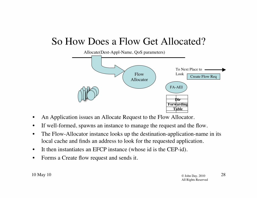
10 May 10 28© John Day, 2010All Rights Reserved
So How Does a Flow Get Allocated?
• An Application issues an Allocate Request to the Flow Allocator.• If well-formed, spawns an instance to manage the request and the flow.• The Flow-Allocator instance looks up the destination-application-name in its
local cache and finds an address to look for the requested application.• It then instantiates an EFCP instance (whose id is the CEP-id).• Forms a Create flow request and sends it.
Allocate(Dest-Appl-Name, QoS parameters)
FlowAllocator
DirForwarding
Table
FA-AEI
Create Flow Req
To Next Place toLook

10 May 10 29© John Day, 2010All Rights Reserved
At The Next Place To Look
• Create Flow Request arrives at the next place to look.• Flow Allocator looks up the destination application name in its “local cache”• Address returned isn’t ours, so not here.• Send it there
FlowAllocator
DirForwarding
Table
Create Flow Req
To Next Place toLook
Create Flow Req
Is this the place?

10 May 10 30© John Day, 2010All Rights Reserved
Stepping BackEstablishing Communication
• Remember this?• We go along looking for places to look for the requested application.
A BAhh, a big leap!

10 May 10 31© John Day, 2010All Rights Reserved
Yet Another Place to Look
• Create Flow Request arrives at yet another place to look.• Flow Allocator looks up the destination application name in its “local cache”• Address returned is ours. Its here! Check requestors credentials, if okay.• Deliver Allocate indication to the destination application• Which accepts or rejects, if accepts sends a Create Flow Response and• Instantiates a EFCP-instance• The connection is established.
FlowAllocator
DirForwarding
Table
Create Flow Req
Is this the place?
DestApplication Allocate
Indication
AllocateConfirm
Create Flow Resp
Send to Requestor.

10 May 10 32© John Day, 2010All Rights Reserved
Finishing UpEstablishing Communication
• The Create Flow Response is sent back to the originator.• Data can now flow.
– Remember we instantiated the EFCP at the source before we started.– Just in case data gets back before the Create Response.
• Either end may start the Application Protocol exchange.
A BAhh, here it is!

10 May 10 33© John Day, 2010All Rights Reserved
The Flow is Now Allocated
• The Create Flow Response arrives from the Destination• The Application is notified that the Allocate was successful and is given a
port-id (in Unix this might be a file descriptor), i.e. the FA-AEI-identifier.• The application can now start exchanging information.
FlowAllocator
DirForwarding
Table
FA-AEI
Create Flow Resp
Response Arrives

10 May 10 34© John Day, 2010All Rights Reserved
The Management SideRIB Daemon
• The OIB/RIB Daemon is a generalization and combination of threefacilities: routing update, event management and the managementagent and performs the following:
– periodically request or notify all or a subset of members of the current value of selectedinformation (routing update);
– upon certain events, notify all or a subset of members of the current value of selectedinformation;
– the latter implies that all event notifications occurring within the DIF should be delivered to theRIB Daemon because there may be a subscription that is triggered by the event, (eventmanagement);
– given that elements of the DIF members should be able to request immediate notification of anevent’s arrival, have it recorded in the RIB, or both (event management);
– if a log of events received is to be kept (the black box function), then the RIB Daemon is thenatural place or it (event management);
– given that the RIB Daemon responds to requests for information from other members of theDIF, then it is the natural place to respond to external requests for information from the DIFManagement System (DMS), (management agent).
10 May 10 35© John Day, 2010All Rights Reserved
The Management SideResource Allocator
• The resource allocator is the core of management in theIPC Process. The degree of decentralization depends onthe policies and how it is used.
• The RA has a set of meters and dials that it can manipulate• The meter fall in 3 categories:
– Traffic characteristics from the user of the DIF– Traffic characteristics of incoming and outgoing flows– Information from other members of the DIF

10 May 10 36© John Day, 2010All Rights Reserved
The Management SideResource Allocator
• The Dials– Creation/Deletion of QoS Classes– Data Transfer QoS Sets– Modifying Data Transfer Policy Parameters– Creation/Deletion of RMT Queues– Modify RMT Queue Servicing– Creation/Deletion of (N-1)-flows– Assignment of RMT Queues to (N-1)-flows– Forwarding Table Generator Output

10 May 10 37© John Day, 2010All Rights Reserved
Initial Draft of a MIB: IIPC Process
Authentication
AllocationAE ResourceAllocation
SecurityManagement
SDUProtection
Mngt
AccessControl
PDU ForwardingTable
(N-1)-Flow Mngr
DirectoryForwarding
Table
Data Transfer
AllocationAEI
Forwarding TableGenerator Policy
(e.g. Routing)
Res AllocPolicy
One to One
One to Many

10 May 10 38© John Day, 2010All Rights Reserved
Initial Draft of a MIB: II
Class ofService
DTP DTCP
Flow Ctl Rexmsn Ctl
RMT
Data Transfer
SDU Protection
QoS Queues
DT-SV
(N)-Flowa
(N-1)-Flows
Dest Addr
Obs. Perf
Reassemb Q
PolicyParams
PolicyParams
PDU ForwardingTable

10 May 10 39© John Day, 2010All Rights Reserved
Transition? No, Adoption
• Adopt. Don’t transition.– If the old stuff is okay in the Internet e-mall, leave it there.– Do the new sophisticated stuff in RINA
• Operate RINA over, under, around and through the Internet.– The Internet can’t be fixed, but it will run better over RINA.– New applications and new e-malls will be better without the legacy and
run better along side or over the Internet.• Microsoft tried to prolong the life of DOS.
– It still haunts them.• A clean break with the past. The legacy is just too costly.• We need engineering based on science, not myth and tradition.
Public Internet
Rina Provider
RINA Network
RINA ApplicationsRINA supported Applications

10 May 10 40© John Day, 2010All Rights Reserved
Aids to AdoptionAn Internet API
• Allows most Internet applications to work over RINA,– Some restrictions on passing addresses since RINA never exposes them.
• If available on both ends, can be faked.
• But with none of the benefits of RINA.– Can only connect to a new instance of an application.– There are several ways to do this. None will give you every aspect of
RINA.
Sockets to RINA API

10 May 10 41© John Day, 2010All Rights Reserved
Aids to AdoptionData Link Diversity
• To deal with the diversity at the media, use the legacy data transferprotocols, but manage it with RINA.– Provides better management.– There would be some advantage to moving to RINA data transfer as well.
• Fewer protocols, less parts count, less cost, easier management, higherperformance, etc.
– But as an Aid to Adoption, this can be investigated.
Legacy Data LinkProtocols, e.g. 802.x etc.
RINAManagement

10 May 10 42© John Day, 2010All Rights Reserved
Next Steps
• Standardization– We need multiple implementations to test the concepts, and serve
as a sanity check on implementations and interpretation– To inter-operate, we need to standardize a number of things
• Minimum common object sets and operations• Common concrete syntax(es) and data representation(s)• Interoperable common (sub)sets of policy combinations
– But not all DIFs have to operate within these constraints, soresearch and customization is not hampered
– We need an organization that can help create, promulgate, andsupport these standards - the Pouzin Society

10 May 10 43© John Day, 2010All Rights Reserved
Next Steps (2)
• Implementation Issues– WHY will people do implementations? What can we do to help
them so that we raise the acceptance of this technology?– Many different execution targets: middleware, microkernel, OS,
apps, dedicated/embedded• Different concerns may lead to radically different implementations
– Proprietary concerns• If implementations don’t interoperate, they don’t reinforce one
another• Basic technology and intellectual property needed for interoperable
implementations needs to be availability without burden– Product details can generally be abstracted from DIF/protocols

10 May 10 44© John Day, 2010All Rights Reserved
Next Steps (3)
• Many supporting activities will be fruitful– Research and analysis of concepts– Policy research, separated from the difficulties of making new
concepts work within highly-optimized legacy implementations– Tools for measurement, testing, configuration, and analysis of
implementations– Tools to generate and run simulations based on common
mechanism, with experimental policies plugged in as appropriate• Impractical with hand-coded implementations of protocols• Opens new opportunities for research into protocol behavior and
design

10 May 10 45© John Day, 2010All Rights Reserved
Next Steps (4)
• We’ll be meeting this week to discuss all these issues -please feel free to join us!

10 May 10 46© John Day, 2010All Rights Reserved
Conclusions
• RINA is a new formulation of how to do networking– It incorporates the lessons of the last 40 years, where we’ve
learned both good and bad ways to do things. We’d like to stepaway from many things that have not worked out well.
– We don’t propose that RINA overnight replace the Internet as weknow it, but rather that we begin a new age of protocol researchand implementation
• To add new capabilities to networks• To make networks more efficient, manageable, and secure• To get past problems that have arisen in where we are now
• RINA is in its early stages of development - join us andhelp us mature it!