Embed Size (px)
Citation preview

SA Journal of Industrial Engineering May 2007 Vol 18(1): 157-173
AN INTRODUCTION TO RAPID CASTING: DEVELOPMENT AND INVESTIGATION OF PROCESS CHAINS FOR
SAND CASTING OF FUNCTIONAL PROTOTYPES
D. Dimitrov1, W. van Wijck2 and N. de Beer3
Laboratory for Rapid Product Development, Department of Industrial Engineering, University of Stellenbosch, South Africa
[email protected]; [email protected]; [email protected]
ABSTRACT This paper discusses the results obtained from studies on different Rapid Tooling process chains in order to improve the design and manufacture of foundry equipment that is used for sand casting of prototypes in final material. These prototypes are intended for functional and pre-production tests of vehicles. The Three Dimensional Printing process is used as core technology. Subsequently, while considering aspects such as time, cost, quality (accuracy and surface roughness), and tool life, a framework is presented for the evaluation and selection of the most suitable process chain in accordance with specific requirements. This research builds on an in-depth characterisation of the accuracy and repeatability of a 3D printing process.
OPSOMMING
Hierdie artikel bespreek die resultate wat verkry is tydens studies op verskillende Snel-Gereedskapvervaardigingproseskettings wat ondersoek is teneinde die ontwerp en vervaardiging van sandgietgereedskap, om prototipes in finale materiaal te vervaardig, te verbeter. Die prototipes is bestem vir gebruik in funksionele- en voor-produksietoetse van voertuie. Die sogenaamde Driedimensionele Drukproses (3DP) is as kerntegnologie aangewend. Gevolglik, na oorweging van aspekte soos tyd, koste, kwaliteit (akkuraatheid en oppervlakafwerking), en gereedskapleeftyd, is ’n raamwerk ontwikkel vir die evaluering en seleksie van die mees geskikte prosesketting met inagname van spesifieke vereistes. Hierdie navorsing bou op ’n diepgaande karakterisering van die akkuraatheids- en herhaalbaarheidsvermoë van ’n 3D drukproses.
http://sajie.journals.ac.za

158
1. INTRODUCTION The development of innovative products – and their realisation by means of advanced manufacturing methods and process combinations – is becoming more and more a key issue in international competitiveness. However, although many companies understood and started to appreciate the practicality of Rapid Prototyping (RP) (or Layer Manufacturing), especially in shortening the design cycle so that products can reach the market quickly, they still refrain from adopting it for various reasons. Some believe RP systems are too fancy, while others find the materials lacking in certain qualities. Over the past few years, though, Layer Manufacturing (LM) methods have substantially advanced, to the point where they can now provide vital strategic benefits to various organisations. One area of application where these technologies have begun to reach a critical mass is in the development and production of prototype tooling for different forming processes (Dieckhues [1], Ederer et al. [2]). There is often a need to manufacture a limited number of parts (typically fewer than 100) for design validation, proof of concept, pre-production tests (e.g. of vehicles), or for design check and approval of production tooling. The most essential advantage is the integration of production planning and testing within the product development phase.
In recent years Three Dimensional Printing (3DP) has come to the fore as a very competitive process in terms of cost and speed, and sales of these machines have increased significantly compared with other RP equipment (Wohlers [3]). These devices were developed, and are still seen, mostly as a “concept modeller”. However, with the improved availability of materials in 3DP, as well as the wide variety of infiltrating agents and post treatment procedures, the scope for this technology is expanding quickly – far beyond the original idea of generating design iterations. Some of the earlier manufacturing applications, such as investment casting, became trivial; others, such as sand casting, opened up new possibilities. Depending on the needs, the technology allows one to build a mould in sand straight from the CAD file, or to fabricate cores and cavities in different materials. The next challenge is the development of optimised process chains to minimize lead times and production costs, while still ensuring high quality castings. This is needed in different production scenarios related to:
• the size of production runs • part size • part complexity, and • the cast materials involved. Over the last few years, the industrial sector consistently and predominantly using LM technologies has been the automotive branch (Wohlers [3]). Based on an in-depth investigation of the achievable accuracy and repeatability of the implemented system (Dimitrov et al. [4,5]), this study illustrates, with a selected component from the automotive industry, the quest to produce prototype parts in final material and to shorten the development time at reasonable cost.
http://sajie.journals.ac.za
159
2. LAYER MANUFACTURING – A BRIEF OVERVIEW Layer Manufacturing techniques are digitally-driven, additive processes that allow the automated production of physical, three dimensional objects. The objects are built layer-by-layer from thin, horizontal cross sections of a 3D CAD model by using liquid, powder, or sheet materials. Currently, more than 35 commercially available RP Systems have been developed. They vary in operation costs, production speed, accuracy, materials used, and process capabilities. Some of the most prominent processes include Stereolithography (SLA), Fused Deposition Modelling (FDM), Selective Laser Sintering (SLS), and 3D Printing (3DP). The SLA technology involves a process that solidifies layers of ultraviolet (UV) light-sensitive liquid polymer using a laser. The FDM process constructs objects by using a temperature-controlled head extruding thermoplastic material, while the SLS process uses thermal energy from a laser to fuse the particles of powdered materials. During this study, a 3D Printer from Z Corporation, with a build volume of 200 x 250 x 200 mm, was utilised. It uses a printer cartridge to deposit a two dimensional profile of resin on to the layer of powder that forms the build surface. Similar to the SLS process, the base material is rolled on to the build platform. The prototype grows as hundreds of layers of powder are bound one on top of the other. Depending on the application, essentially four types of powder are used: a plaster-based powder (zp102), a starch-based powder (zp15e), a hybrid compound between the two (zp250), and a ceramic compound material (ZCast501) that is implemented for mould and/or core production. The plaster-based zp102 has a finer grain size than the starch based powder, and allows thinner layers to be spread (0.08-0.1mm); therefore a better accuracy and surface finish can be achieved. The layer thickness of both zp250 and ZCast501 is about 0.125mm. After printing, parts can be infiltrated with various agents in accordance with their purpose. In the study presented here, the plaster-based zp102 was infiltrated with an epoxy-type material, while the ceramic compound material, ZCast501, was used in its baked form. 3. PROCESS CHAINS FOR PROTOTYPE SAND CASTING Using 3DP technology, several process chains with variations of powder material (plaster and ceramic) as well as the tooling methods for Sand Casting applications were developed. Four of them were further investigated (Centner [6], Eckert [7]). 3.1 Direct Metal Casting (ZCast) The ZCast™ Direct Metal Casting consists of materials and processes that allow designers and engineers to build moulds (copes and drags) and/or cores directly from a CAD file (Figure 1a). It eliminates the pattern creation phase of the traditional sand casting process in a revolutionary way, resulting in a drastic reduction of the casting lead time from weeks to days (Krouth [8]). The process involves the design of basic parting lines and coring. A 3D mould shell approximately 25mm thick is printed using ZCast plaster-ceramic composite material. If necessary, the shell is created
http://sajie.journals.ac.za
160
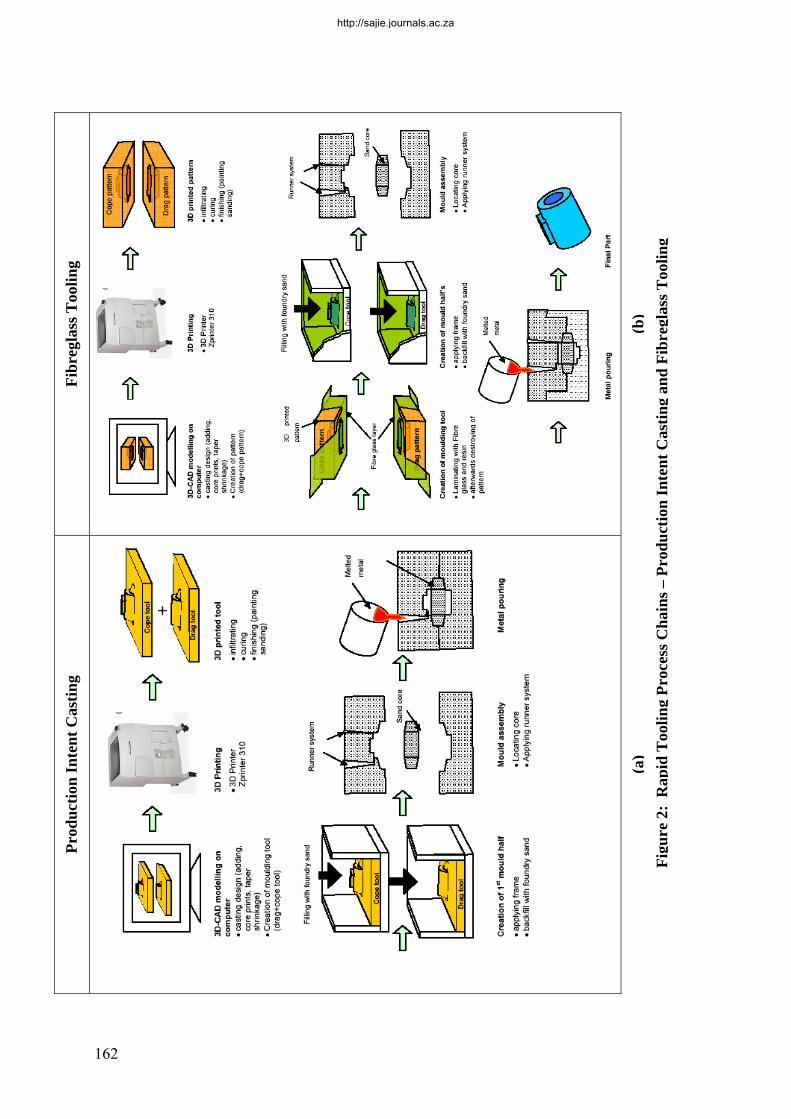
with ribbing and backfilled with traditional foundry sand to give added strength while minimizing material cost. 3.2 Loose Pattern Method (LP) The Loose Pattern (LP) method is a familiar and well-established technique in the casting industry. The steps of this process are shown in Figure 1b. According to conventional techniques, the patterns are usually made of wood or plastic. Implementing modern technologies, these patterns can be produced using 3D Printing. Printed parts, having been infiltrated, are aligned on a joint board. Around the pattern, a dividing surface (split line) has to be created manually by using resin-mixed foundry sand or similar materials. The pattern stays loosely seated so that the process of creating the split line can be repeated for the other mould half, using the same pattern. The two joint boards are framed with wood which, along with the 3D Printed pattern, constitutes the final foundry tool. Mould halves are then created separately by interchanging the pattern between the two core boxes. 3.3 Production Intent Casting (PIC) This method is a combination of the zp102 plaster material for creating patterns, and ZCast material for creating cores (Figure 2a). It first involves the creation of the foundry tooling as it would be designed for the production foundry process, including core prints, offset partings, and clearances (Krouth [8]). The pattern equipment is then printed with the zp102 material, infiltrated with epoxy, and if necessary backfilled with a rigid plastic filler for added strength. If cores are required, they may be produced using the ZCast material. 3.4 Fibreglass Tooling (FGT) Finally, the fourth process investigated makes use of fibreglass material to enhance the strength of the foundry tooling. Like the previous two, this process chain (Figure 2b) begins from a CAD model with split line and core designs. The pattern halves are then printed using zp102 plaster material. Fibreglass material is applied to the split surface and sides of the mould. The pattern is removed from its contact surface with the fibreglass. The resulting positive fibreglass geometry is then mounted on a wooden frame, and is used to create the subsequent sand moulds necessary for sand casting. Where cores are involved, patterns of the core geometry are printed using zp102 material, and used to create core boxes.
http://sajie.journals.ac.za

161
Loo
se P
atte
rn M
etho
d
(b)
ZC
ast M
ould
s for
San
d C
astin
g
(a)
Figu
re 1
: Rap
id T
oolin
g Pr
oces
s Cha
ins –
ZC
ast M
ould
s for
San
d C
astin
g an
d L
oose
Pat
tern
Met
hod
http://sajie.journals.ac.za
162
Fibr
egla
ss T
oolin
g
(b)
Prod
uctio
n In
tent
Cas
ting
(a)
Figu
re 2
: R
apid
Too
ling
Proc
ess C
hain
s – P
rodu
ctio
n In
tent
Cas
ting
and
Fibr
egla
ss T
oolin
g
http://sajie.journals.ac.za

163
4. ANALYSIS AND EVALUATION OF DEVELOPED PROCESS CHAINS 4.1 Factors influencing the evaluation and choice of process chains When considering the individual strengths and capability levels of the processes as described above, it becomes clear that, depending on the circumstances and desired output, some are more suitable to implement than other. Some of the factors determining the best candidate for the required results are shown in Figure 3.
Affordability
Part Complexity
Process Chain
Time Demand Part Size
Accuracy Required
MaterialNumber of Parts
Figure 3: Factors influencing the process chain selection
Figure 4: Model for decision-making and experimental analysis From the factors identified, a model for decision-making and experimental analysis was developed (Figure 4). Starting from a customer request, the model shows how several incoming process chains can be compared on the basis of being able to produce Rapid Tooling that will realize the requested customer product(s). The process chains undergo a sifting process. The first filter concerns proof of the process
http://sajie.journals.ac.za
164
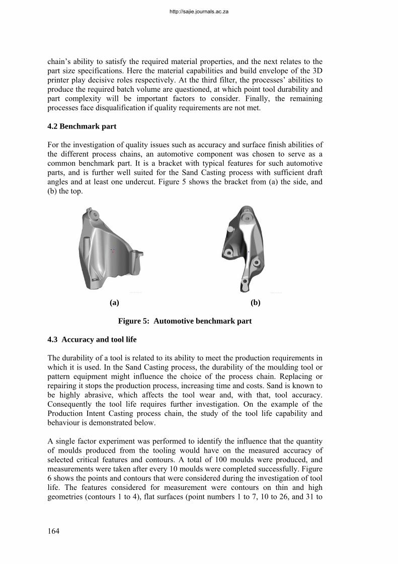
chain’s ability to satisfy the required material properties, and the next relates to the part size specifications. Here the material capabilities and build envelope of the 3D printer play decisive roles respectively. At the third filter, the processes’ abilities to produce the required batch volume are questioned, at which point tool durability and part complexity will be important factors to consider. Finally, the remaining processes face disqualification if quality requirements are not met. 4.2 Benchmark part For the investigation of quality issues such as accuracy and surface finish abilities of the different process chains, an automotive component was chosen to serve as a common benchmark part. It is a bracket with typical features for such automotive parts, and is further well suited for the Sand Casting process with sufficient draft angles and at least one undercut. Figure 5 shows the bracket from (a) the side, and (b) the top.
(a) (b)
Figure 5: Automotive benchmark part
4.3 Accuracy and tool life The durability of a tool is related to its ability to meet the production requirements in which it is used. In the Sand Casting process, the durability of the moulding tool or pattern equipment might influence the choice of the process chain. Replacing or repairing it stops the production process, increasing time and costs. Sand is known to be highly abrasive, which affects the tool wear and, with that, tool accuracy. Consequently the tool life requires further investigation. On the example of the Production Intent Casting process chain, the study of the tool life capability and behaviour is demonstrated below. A single factor experiment was performed to identify the influence that the quantity of moulds produced from the tooling would have on the measured accuracy of selected critical features and contours. A total of 100 moulds were produced, and measurements were taken after every 10 moulds were completed successfully. Figure 6 shows the points and contours that were considered during the investigation of tool life. The features considered for measurement were contours on thin and high geometries (contours 1 to 4), flat surfaces (point numbers 1 to 7, 10 to 26, and 31 to
http://sajie.journals.ac.za

165
33), areas designated for machining (m1 to m4), and sharp corners.
Figure 6: Measured points and contours during tool life investigation
4.3.1 Freeform contour geometries Four freeform contours were measured on the cope-half tool. Figure 7 shows the measured lines for Contour 2 as an example. The other three contours showed similar magnitudes of deviation. As seen in the picture, tool wear acts in the negative direction. (Some points deviate more than 0.3mm in the positive direction, but these are attributed to adhering sand grains.) The thick dark line refers to the first measurement, which was used as a reference for the others. A zoomed-in view of an area with high deviation (Figure 7b) shows that the curves are mainly below the ones of the first measurement. That means that contours become smaller because of the abrasion and the compression of the moulding tool. The curves differ strongly. For example, the biggest deviation (approximately -0.14mm occurring after 60 moulds) is seen to deviate by only -0.07mm at the same Y-value after 100 moulds. This shows that the deviation of the moulding tool is not only affected by steady abrasion, but also by other factors. Typically for the foundry practice, at regular intervals – normally after every 50-60 mouldings – the tool is coated with release agent to ease the moulding procedure. This explains the observed phenomenon. It is also interesting to note that the frequency of the curves becomes higher after 20 moulds, indicating a higher surface roughness due to scratches and notches. The waviness faded out considerably after 50 to 60 mouldings, and then picked up slightly again at about 100 moulds. This can be explained by the random character of the wearing process, as surface roughness combines with the coating of the tool mentioned above. Generally, the tool deviation increases almost steadily to about 50-60 moulds before
http://sajie.journals.ac.za

166
it climbs back after coating. It can be seen that the deviation level is higher at surfaces which are orthogonal to the moulding direction. These orthogonal faces have larger surface areas exposed to pressures during the packing process of the sand into the moulding tool. Therefore, a possible reason for observing higher deviations at these geometries is that a measure of material compression occurs in the moulding tool itself.
(a) Contour 2
(b) Contour 2-1: Zoom in on Contour 2 higher deviation area
Figure 7: Freeform contour geometry measures (Eckert [7])
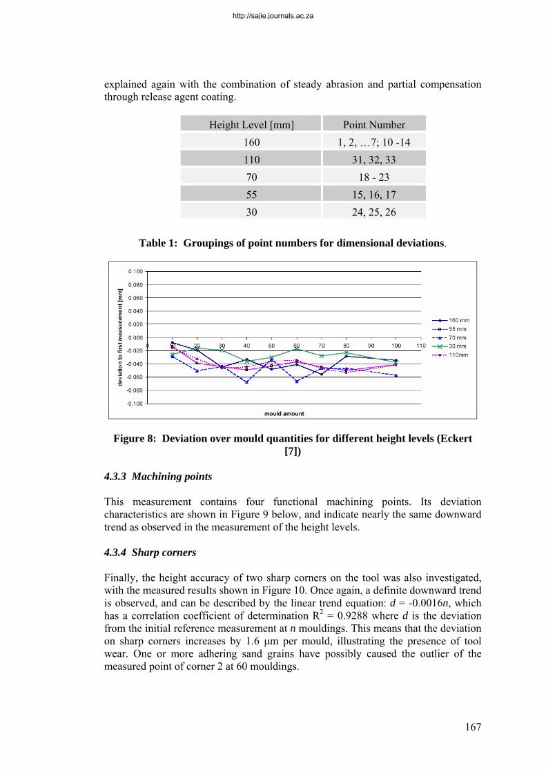
4.3.2 Dimensional deviations The 27 points used to measure dimensional deviations were located at different Z-heights, and formed the groups as shown in Table 1. The average deviation from the first measurement of each group in accordance with the number of moulds produced is given in Figure 8. It shows that the deviation starts at a higher value (an average of -0.02mm) at the beginning and ends at an approximate average of -0.05 mm, confirming the general pattern and tendency of deviation value increase with mould number produced. This observation can be
http://sajie.journals.ac.za
167
explained again with the combination of steady abrasion and partial compensation through release agent coating.
Height Level [mm] Point Number 160 1, 2, …7; 10 -14 110 31, 32, 33 70 18 - 23 55 15, 16, 17 30 24, 25, 26
Table 1: Groupings of point numbers for dimensional deviations.
Figure 8: Deviation over mould quantities for different height levels (Eckert
[7]) 4.3.3 Machining points This measurement contains four functional machining points. Its deviation characteristics are shown in Figure 9 below, and indicate nearly the same downward trend as observed in the measurement of the height levels. 4.3.4 Sharp corners Finally, the height accuracy of two sharp corners on the tool was also investigated, with the measured results shown in Figure 10. Once again, a definite downward trend is observed, and can be described by the linear trend equation: d = -0.0016n, which has a correlation coefficient of determination R2 = 0.9288 where d is the deviation from the initial reference measurement at n mouldings. This means that the deviation on sharp corners increases by 1.6 μm per mould, illustrating the presence of tool wear. One or more adhering sand grains have possibly caused the outlier of the measured point of corner 2 at 60 mouldings.
http://sajie.journals.ac.za

168
Figure 9: Deviation over mould quantities for machining points (Eckert [7]) Summarising the results of previous research and of this study, the dimensional and geometric accuracy of the moulding tool is within a tolerance field of ±0.8 mm over 100 mouldings. A pattern and pattern equipment of this size and tolerance allowances meets code H3 (grade IT14 of ISO) of the European Norm EN 12890, which classifies foundry equipment for the production of sand moulds and cores. It also complies with the requirements for prototype production. However, the target should be to improve tool accuracy and wear characteristics in order to meet higher standards, such as H2, and thus the accuracy requirements for higher production volumes and even machine moulding. 4.4 Influence of complexity The effect of part complexity on manufacturing time and costs is difficult to predict. The layer-wise method of fabrication employed by the 3D printer allows one to create products with virtually no limitation in complexity. The preceding data preparation, and most importantly the CAD modelling of pattern and moulds – as well as the post-processing steps in producing patterns and tooling equipment through these process chains – can, however, be heavily influenced by the complexity of a part. As a result the choice of the most suitable process is also influenced. To avoid attributing a level of complexity to a part based merely on subjective factors, the challenge was to develop a method for classifying parts designated for the Sand Casting process. A number of classification methods were considered (Ambos et al. [9], Chua et al. [10]). Poli [11] determines complexity of parts for plastic injection moulding by their geometrical features, such as internal and external undercuts, surface finish, texture, dimensional tolerances, and dividing surface (split-line) configuration. Similarly, sand casting demands the consideration of undercuts, draft angles, and split-line configuration as the design attributes that have the most influence on manufacturing difficulty, as well as the time and costs involved. The different undercuts in particular have to be taken into account. Their type and number can require a variety of cores and so lead to a complex core system, which in turn represents to a large extent the complexity of a sand cast component (Campbell
http://sajie.journals.ac.za

169
[12]).
Figure 10: Measured deviations of corners per mould quantity, Eckert [7]
Therefore, in order to define the basic complexity of a part from a manufacturing point of view (not yet considering specific feature and surface complexities such as holes, depressions, bosses, ribs, and textures), this study has defined part complexity based on the number of internal and external undercuts as well as the configuration of its split-line surface. Based on these factors, a complexity code was developed to define a specific part’s complexity, as shown in Figure 11:
<X> / <YY> / <Z>
Where X = 0, 1, M → Denoting the number of internal undercuts, M referring to more than one.
YY = P or NP → Denoting if the split-line surface is planar or non-planar Z = 0, 1, M →
Denoting the number of external undercuts, M referring to more than one.
0/P/0 Describes a part with no internal undercuts that will require a planar surface between mould halves, and has no external undercuts. This represents the least complex part.
Examples
M/NP/M Describes a part with more than one internal undercut that will have a non-planar surface between mould halves, and has more than one external undercut. Within this classification, this configuration is considered most complex.
Figure 11: Complexity code defined (Eckert [7])
4.5 Time and cost comparison To investigate the influence of part complexity on manufacturing time and cost in the selection of the most suitable process chain, two parts representing the simplest and the most complex configuration in accordance to the defined complexity code were constructed. The tooling required to produce these benchmark parts was made in accordance with the ZCast, LP, and PIC methods, whereas for the FGT (not shown
http://sajie.journals.ac.za

170
on the graphs) the results were estimated. Figure 12 experimentally shows the time
020406080
100120140160
0 5 10 15 20 25 30 35 40 45 50 55 60 65 70 75 80 85 90 95 100Part Quantity
Tim
e [h
r]ZCast Shell method part 1/1 ZCast Shell method part 6/3
Loose Pattern method part 1/1 Loose Pattern method part 6/3
Production Intent Casting part 1/1 Production Intent Casting part 6/3
0
(a)
0
5,000
10,000
15,000
20,000
25,000
30,000
0 5 10 15 20 25 30 35 40 45 50 55 60 65 70 75 80 85 90 95 100Part Quantity
Cos
t [R
]
ZCast Shell method part1/1 ZCast Shell method part 6/3
Loose Pattern method part 1/1 Loose Pattern method part 6/3
Production Intent Casting part 1/1 Production Intent Casting part 6/3
0
(b)
Figure 12: Comparison of manufacturing time (a) and cost (b) per Rapid Tooling process chain (Eckert [7])
and costs associated with manufacturing the necessary tooling for each process, as well as extrapolations to produce 100 parts (the batch size normally required for planning and pre-production tests). Apart from the general tendency represented by the slopes (variable time and costs) of each line and their respective starting points (showing fixed time and costs), these graphs give a clear indication of the influence of the tool life and part complexity on the process chain selection. For example, in cases where up to four cast components of high complexity are required, the ZCast
http://sajie.journals.ac.za
171
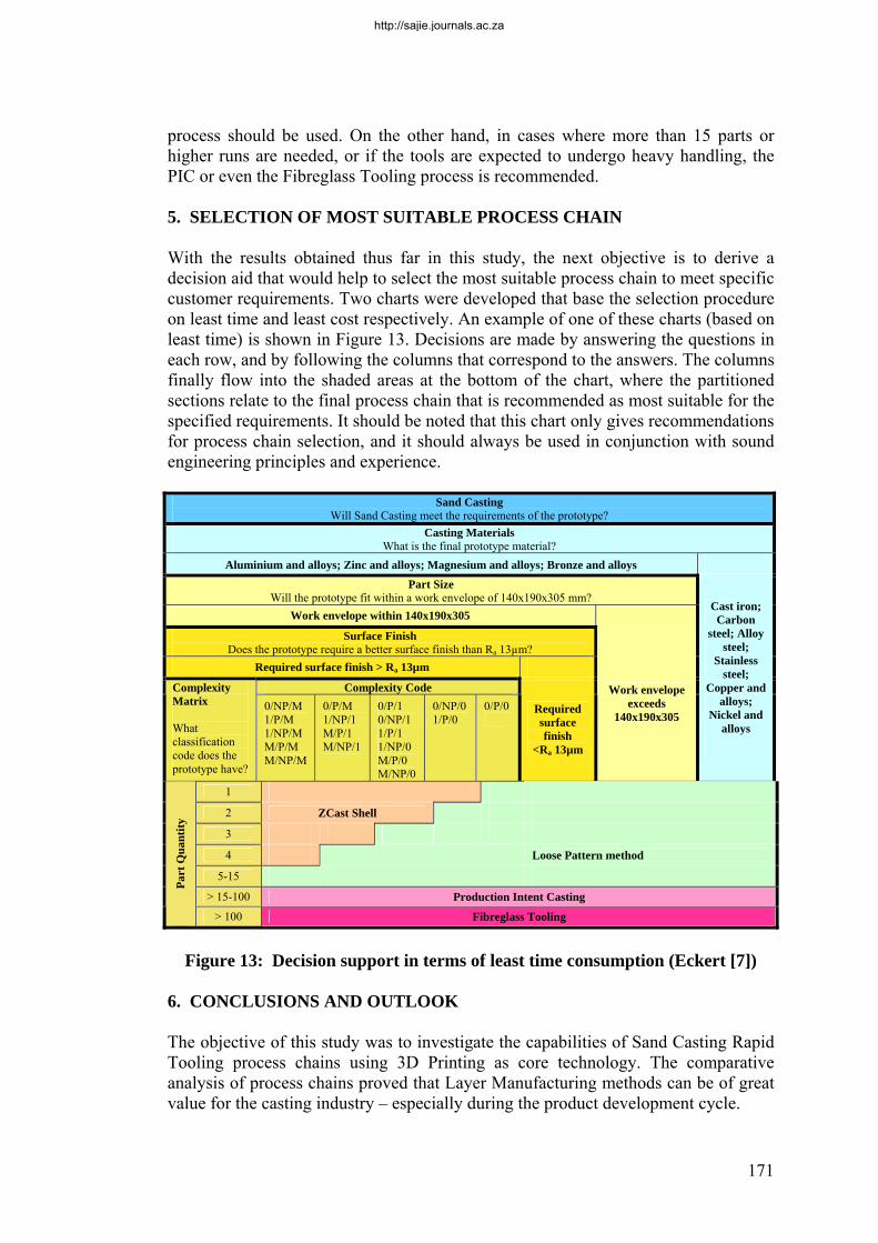
process should be used. On the other hand, in cases where more than 15 parts or higher runs are needed, or if the tools are expected to undergo heavy handling, the PIC or even the Fibreglass Tooling process is recommended. 5. SELECTION OF MOST SUITABLE PROCESS CHAIN With the results obtained thus far in this study, the next objective is to derive a decision aid that would help to select the most suitable process chain to meet specific customer requirements. Two charts were developed that base the selection procedure on least time and least cost respectively. An example of one of these charts (based on least time) is shown in Figure 13. Decisions are made by answering the questions in each row, and by following the columns that correspond to the answers. The columns finally flow into the shaded areas at the bottom of the chart, where the partitioned sections relate to the final process chain that is recommended as most suitable for the specified requirements. It should be noted that this chart only gives recommendations for process chain selection, and it should always be used in conjunction with sound engineering principles and experience.
Sand Casting Will Sand Casting meet the requirements of the prototype?
Casting Materials What is the final prototype material?
Aluminium and alloys; Zinc and alloys; Magnesium and alloys; Bronze and alloys Part Size
Will the prototype fit within a work envelope of 140x190x305 mm? Work envelope within 140x190x305
Surface Finish Does the prototype require a better surface finish than Ra 13µm?
Required surface finish > Ra 13µm Complexity Code Complexity
Matrix What classification code does the prototype have?
0/NP/M 1/P/M 1/NP/M M/P/M M/NP/M
0/P/M 1/NP/1 M/P/1 M/NP/1
0/P/1 0/NP/1 1/P/1 1/NP/0 M/P/0 M/NP/0
0/NP/0 1/P/0
0/P/0
Required surface finish
<Ra 13µm
Work envelope exceeds
140x190x305
Cast iron; Carbon
steel; Alloy steel;
Stainless steel;
Copper and alloys;
Nickel and alloys
1 2 ZCast Shell 3 4 Loose Pattern method
5-15 > 15-100 Production Intent Casting
Part
Qua
ntity
> 100 Fibreglass Tooling
Figure 13: Decision support in terms of least time consumption (Eckert [7])
6. CONCLUSIONS AND OUTLOOK The objective of this study was to investigate the capabilities of Sand Casting Rapid Tooling process chains using 3D Printing as core technology. The comparative analysis of process chains proved that Layer Manufacturing methods can be of great value for the casting industry – especially during the product development cycle.
http://sajie.journals.ac.za
172
Several factors influence the decision about the most suitable process chain, depending on the given circumstances and customer requirements. Based on the results from a case study, a model and decision support tables could be developed, based on either least time consumption or least cost. Depending (among other things) on the required run size and part complexity, the most suitable combination of established and new methods should be used. Thus these diagrams can be used in the planning of prototype production too. The presented results should be seen as part of ongoing research aimed at the development of a generalised approach for sand casting rapid tooling process chain design, evaluation, and selection, involving other LM technologies and equipment as well. 7. REFERENCES [1] Dieckhues, G., 2005. Rapid production of functional castings components,
Casting SA, Volume 6, No 3, October 2005, pp 35-38. [2] Ederer, I., Höchsmann, R, 2005. Patternless production of furan bonded sand
moulds in rapid prototyping, Casting SA, Volume 6, No 4, December 2005, pp 35-38.
[3] Wohlers, T. 2005. Wohlers Report, Rapid Prototyping, Tooling & Manufacturing State of the Industry, Fort Collins, Colorado, USA.
[4] Dimitrov, D., Van Wijck, W., Schreve, K., De Beer N., 2003. An Investigation of the Capability Profile of the Three Dimensional Printing Process with an Emphasis on the Achievable Accuracy, Annals of the CIRP, Vol 52/1: pp 189-192.
[5] Dimitrov, D., Van Wijck, W., Schreve, K., De Beer, N., 2006. Investigating the Achievable Accuracy of Three Dimensional Printing, Rapid Prototyping Journal, Vol.12 No1, 2006, Emerald Group Publishing Limited, pp 42 -52.
[6] Centner, T., 2005. Development of Optimal Process Chains for Sand Casting of Automotive Prototype Parts Using Layer Manufacturing Methods as Core Technology, Thesis Report, University of Stellenbosch, South Africa.
[7] Eckert, S., 2005. Investigation and Design of Optimised Process Chains Using Additive Methods for Sand Casting of Automotive Parts, Thesis Report, University of Stellenbosch, South Africa.
[8] Krouth, T.J., 2002. Foundry Tooling and Metal Castings in Days, Proceedings from International Conference: Worldwide Advances in Rapid and High-Performance Tooling, EuroMold, Frankfurt/M, Germany.
[9] Ambos, E., Hoffmann, I., Krötzsch, S., Miersch, N., Pfisterer, W., Scheler, R., 2000. Effektivitätsstegerung durch Einsatz rechentechnischer Lösungen in der Arbeitsvorbereitung, Newspaper GIESSEREI 87 Nr. 10, 10 October: pp 39-45.
[10] Chua, C.K., Leong, K.F., Lim, C.S., 2003. Rapid Prototyping, Principles and Applications, 2nd Edition, World Scientific, Singapore.
[11] Poli, C., 2001. Design for Manufacturing, A Structured Approach, 1st Edition, Butterworth Heinemann, Oxford.
http://sajie.journals.ac.za

173
[12] Campbell, J., 2004. Castings Practice, Elsevier Butterworth-Heinemann, Oxford.
http://sajie.journals.ac.za