Embed Size (px)
Citation preview
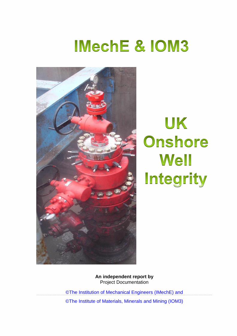
An independent report by Project Documentation
©The Institution of Mechanical Engineers (IMechE) and
©The Institute of Materials, Minerals and Mining (IOM3)
UK Onshore Well Integrity
Page 2 of 41
CONTENTS
1. INTRODUCTION Purpose What is well integrity? Background Project Driver
2. CONCLUSIONS & OBSERVATIONS Conclusions Observations
3. WHY SHALE GAS IN THE UK? Concerns Future gas prospects Gas represents Energy security Major economic benefits of shale gas
4. PROJECT METHODOLOGY
Methodology Project Documentation Workshop Workshop Feedback Introduction to Risk Assessment with Case Study on Shale Gas
5. CONTEXT UK Onshore Shale Gas Well Construction and Operation Well Integrity and UK Requirements The Role of the Well Examiner
6. DOCUMENTATION REVIEW Key documents reviewed Regulations Guidelines
7. IMechE/IOM3 OPERATOR SURVEY Background Objectives Responses
8. WORK IN PROGRESS Ongoing studies
9. APPENDIX Additional documents reviewed
10. GLOSSARY Common abbreviations, terms and definitions used

UK Onshore Well Integrity
Page 3 of 41
SECTION 1
INTRODUCTION

UK Onshore Well Integrity
Page 4 of 41
Introduction
Purpose
The purpose of this report is to detail the existing regulations and guidelines in
respect of well integrity in oil & gas exploration and production on the UK
mainland, with specific reference to shale gas.
This report is primarily to inform the general public about onshore well integrity and
to give an informed view of current practices.
What is Well Integrity? Oil & Gas UK defines well integrity as “the application of technical, operational and organizational solutions to reduce the risk of uncontrolled release of formation fluids throughout the life cycle of the well”. Background
Following the discovery of substantial gas reserves in the North Sea in the early
1960’s the United Kingdom (UK) moved from coal to gas as the fuel of choice for
power generation and domestic heating/cooking. This trend was accelerated in
recent years in an effort to reduce carbon dioxide emissions, with gas being
viewed as a cleaner fuel than coal.
Domestic gas production from the UK Continental Shelf (UKCS) is insufficient to
meet UK demand, currently supplying around 48% of demand. The UK is therefore
reliant on importing gas to meet the majority of the demand. Approximately 38% of
UK gas is supplied through pipelines from continental Europe and Scandinavia.
With the remaining 14% of demand being met by Liquefied Natural Gas (LNG)
supplied by ships, primarily from the Middle East. Imported gas is less secure than
domestic gas, has commercial risks associated with currency exchange rates, has
a negative impact on the UK balance of payments and does not contribute the
revenue associated with gas production into the UK economy.
The United States (US) has led the large-scale development of shale oil and gas
using high volume hydraulic fracturing. This has been transformational for the US
economy, by increasing the availability and reducing the cost of this energy
source. But they have a different land-ownership regime. The UK has extensive
onshore shale gas and oil resources located in central Scotland and England. The
UK Government has issued licences to enable companies to undertake
exploration work to determine if UK shale gas and oil can be economically
developed. The first dedicated shale gas well was drilled at Preese Hall in
Lancashire in 2010. During the initial stages of high volume fracturing of the well
low level earth tremors were recorded and the operation was shut down. There
was significant media interest and the UK Government imposed a moratorium on
further activity. The moratorium was lifted following evaluation and agreement on
guidelines for future activity.
UK Onshore Well Integrity
Page 5 of 41
Project Driver
Proposed onshore UK shale gas and oil exploration has continued to attract
significant attention from the media, politicians, environmental groups, protest
groups, business groups and the public at large. Local councilors turned down
an application for further shale gas exploration activity in Lancashire and there is
significant resistance to an application for fracking in North Yorkshire.
The information often used to oppose shale gas extraction through hydraulic
fracturing often includes experience from the US, which is not in line with the UK
regulatory framework.
The various protagonists have tended to make public information that supports
their point of view; this has often included experience from the US, which is not
relevant to the UK. One of the key topics of discussion has been well integrity.
The Institute of Mechanical Engineers and the Institute of Materials, Minerals and
Mining have collaborated to form a joint work group to provide the public with an
engineering view on well integrity pertaining to UK onshore shale gas wells to
assist the public to have an informed view.
This Report reviews the regulatory framework and activities surrounding onshore
UK well integrity, as this covers most areas of concern.
Note: Since this study has started there has been an agreement between Oil &
Gas UK and UKOOG that Issue 3 of the Oil & Gas UK’s OP095 will updated to
incorporate the recommendations of the UKOOG’s Guidelines, thus creating a
single “bible” for both the offshore and onshore Oil & Gas Industry.
UK Onshore Well Integrity
Page 6 of 41
SECTION 2
CONCLUSIONS &
OBSERVATIONS

UK Onshore Well Integrity
Page 7 of 41
Conclusions:
ONSHORE oil and gas operations have been managed safety and with minimal
impact on the UK’s natural and human environment for over 100 years. The
current UK “Goal Setting” Regulatory Regime and associated independent
verification has been found to be robust and effective. This regime has been
further enhanced, in recent years, by the publication of detailed Guidelines
containing good practices to maintain well integrity throughout the well life cycle
from design through to eventual abandonment. The UK Regime is significantly
different to that in the United States of America, which adopts a more prescriptive
approach.
There exists significant knowledge on what can go wrong and the controls
required to remove and manage the risk or mitigate the impacts, should an issue
arise. However, it is also apparent that no ‘one solution’ can be applied across all
assets and that good design, management, engineering judgment and risk
assessment are critical factors in a safe and successful well operation.
UK onshore well operations vary significantly in scale from a few wells to a
hundred or more wells in one Field. Well operators maintain and apply asset
management systems commensurate with the scope and scale of their operations.
The UK Regulators are actively discharging their duties, including site visits where
they are testing the application of good practice and adherence to UK
requirements.
It was noted that there are in effect two documents relating to guidance for well
integrity in the UK: those of the UK Onshore Operators Group (UKOOG) and those
of Oil & Gas UK (OGUK). The OGUK Guidelines cover both onshore and offshore
wells, are endorsed by UKOOG and are cross-referenced from the UKOOG
Guidelines. The action to make the OGUK Well Life Cycle Integrity Guidelines the
industry “bible” for well integrity is supported and encouraged.
UK Onshore Well Integrity
Page 8 of 41
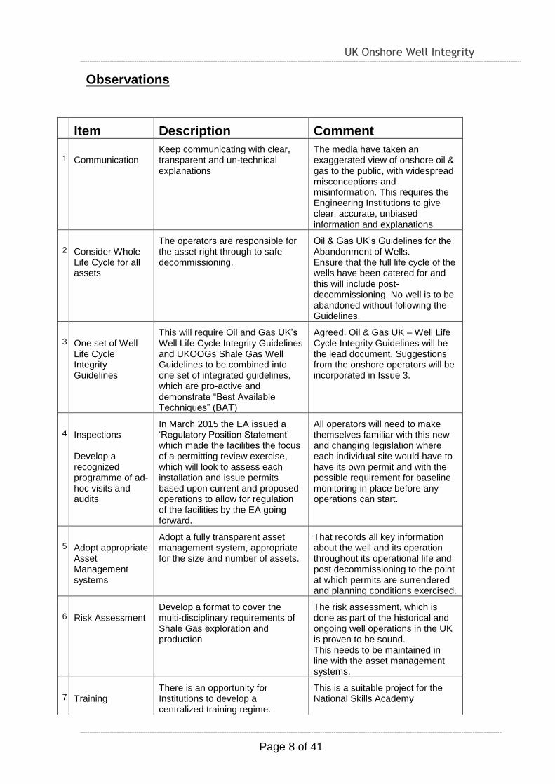
Observations
1 Item Description Comment
11
Communication
Keep communicating with clear, transparent and un-technical explanations
The media have taken an exaggerated view of onshore oil & gas to the public, with widespread misconceptions and misinformation. This requires the Engineering Institutions to give clear, accurate, unbiased information and explanations
22
Consider Whole Life Cycle for all assets
The operators are responsible for the asset right through to safe decommissioning.
Oil & Gas UK’s Guidelines for the Abandonment of Wells. Ensure that the full life cycle of the wells have been catered for and this will include post-decommissioning. No well is to be abandoned without following the Guidelines.
33
One set of Well Life Cycle Integrity Guidelines
This will require Oil and Gas UK’s Well Life Cycle Integrity Guidelines and UKOOGs Shale Gas Well Guidelines to be combined into one set of integrated guidelines, which are pro-active and demonstrate “Best Available Techniques” (BAT)
Agreed. Oil & Gas UK – Well Life Cycle Integrity Guidelines will be the lead document. Suggestions from the onshore operators will be incorporated in Issue 3.
44
Inspections Develop a recognized programme of ad-hoc visits and audits
In March 2015 the EA issued a ‘Regulatory Position Statement’ which made the facilities the focus of a permitting review exercise, which will look to assess each installation and issue permits based upon current and proposed operations to allow for regulation of the facilities by the EA going forward.
All operators will need to make themselves familiar with this new and changing legislation where each individual site would have to have its own permit and with the possible requirement for baseline monitoring in place before any operations can start.
55
Adopt appropriate Asset Management systems
Adopt a fully transparent asset management system, appropriate for the size and number of assets.
That records all key information about the well and its operation throughout its operational life and post decommissioning to the point at which permits are surrendered and planning conditions exercised.
66
Risk Assessment
Develop a format to cover the multi-disciplinary requirements of Shale Gas exploration and production
The risk assessment, which is done as part of the historical and ongoing well operations in the UK is proven to be sound. This needs to be maintained in line with the asset management systems.
77
Training
There is an opportunity for Institutions to develop a centralized training regime.
This is a suitable project for the National Skills Academy
UK Onshore Well Integrity
Page 9 of 41
SECTION 3
WHY SHALE GAS IN THE
UK?

UK Onshore Well Integrity
Page 10 of 41
Why Shale Gas in the UK? The wells mainly under consideration for UK well integrity are those exploring for
shale gas and the economic arguments align with this energy source. Following
identification of the need to collect interested parties together, the IMechE has
held a series of UK Shale Gas “Engineer’s Summits”, in 2014 & 2015, with another
planned for February 2016. These have been entitled “The Engineers’ Summit”, as
it is felt that engineers should understand this topic better and be the advocates.
Concerns
Feedback from these Summits showed a lack of a “Social Charter” to develop
onshore shale gas operations. There are worries about groundwater
contamination, fugitive emissions and induced seismicity, which relate to Well
Integrity. Additionally, continuing misinformation, using bad and misguided
examples from North America stokes this fire, showing there is a need for clear
information that identifies the potential cause of the misgivings and aims to provide
details of the regulatory regime.
Future Shale Gas Prospects
The UK needs new domestic gas supplies, as increasing gas usage will pull in
imports, gas or LNG and cannot be replaced overnight by intermittent renewables,
which, typically only generate electricity.
Recent estimates by the British Geological Survey indicate that the gas in place in
the central shale basin totals up to 1,300 trillion cu.ft. of shale gas, compared with
the total UK annual consumption of gas of around 3tcf
Gas represents (DECC): -
Overall– c.33% of all energy consumed in electrical power generation in 2014
Power – c.27% of UK Electricity generation
Heat – c.83% of UK households
Gas is the “backup” energy source
Feedstock – for the UK chemical industry
Positive impact on the environment
Job creation - £20 bn /year to the UK economy, provides direct and indirect
employment for over half a million people

UK Onshore Well Integrity
Page 11 of 41
Energy Security:
a) Electricity Power Generation
There is a shortage of electrical power in 2015/6, which cannot be made up with
renewables, because they cannot be called up quickly at peak load times and so
not “despatchable”
Generating capacity is falling year-on-year
Current margins of supply vs. demand are below 5.1%?
Without “incentives” this would fall to 1.2%
b) Gas
Gas should not be confused with electricity.
It is a direct source of heat energy and chemical feedstock
Gas is the necessary complement to intermittent renewable energy sources,
increasing gas dependency on imported LNG and pipeline gas from Europe
Environmental benefits of natural gas are: -
Lower Emissions than imported coal
More versatile than renewables
Major economic benefits of shale gas
Jobs – 74,000 (IoD)
Supply chain – peak investment £3.7m/annum (IoD)
Energy security
Tax – important replacement for North Sea revenues
Lower price volatility
Community benefits
Possibility of LNG exports in the future

UK Onshore Well Integrity
Page 12 of 41
SECTION 5
PROJECT
METHODOLOGY
UK Onshore Well Integrity
Page 13 of 41
Methodology:
To conduct an independent and detailed review of the existing UK “published”
onshore energy industry guidance and industry practices for the management of
onshore well integrity and to provide a status report which:
i. Provides a review of the documentation and identifies any potential gaps.
ii. Reviews “other” information/documentation available through service
companies and other organisations.
iii. Considers if these “published” documents are fit for purpose, in the context
of UK guidelines and standards. Where applicable/available use statistical
evidence on historic performance and “other” information/documentation as
presented in well operations documentation
iv. Hold a review workshop with all involved parties to discuss the draft
document and argue the requirements.
v. Publicises the results of the survey to help allay the public’s fears that
onshore well integrity might be an unacceptable risk and if necessary proposes
recommendations that can make the wells/industry safer. Write and publish a
report of the findings, with recommendations for any improvements.
Project Documentation
The documents considered the most important to review for this
project are listed in the Appendix. These documents were
examined for their relevance and completeness. The operators with
onshore licences were subjected to a questionnaire and the results
have been included in Section 7. Workshop
The report draft was made available for comments and reviewed by
15 engineers from the IMechE, IOM3, HSE, EA, Academia,
Consultants, Contractors and Operators, at a full day’s workshop
convened by the IMechE, in November 2015.
Following presentations about the project driver and the current
guidelines, relevant to onshore operations and risk assessment,
there was an open discussion about the necessary requirements
for a safe industry.
Three actual detailed case studies, demonstrating the use of the
OGUK Guidelines, were presented from UK operations, on: -
a. New well construction;
b. Well integrity management system;
c. Well recovery in the event of an issue.
DNV GL presented an introduction to risk analysis and a specific
Case Study relating to shale gas and the potential of groundwater
contamination via cement failures. This was taken from a real life
exercise, as shown below.
UK Onshore Well Integrity
Page 14 of 41
Workshop Feedback:
This report is very comprehensive.
o The Well Integrity Management System used was a
software-based scheme that logs all parameters from all their wells
(approx. 200 wells). This might not suit smaller operators, for whom
a spreadsheet scheme might prove sufficient.
o Should references be made to the upcoming ISO Standard?
- This has been accepted in principle and will be referenced in
Issue 3 of the Guidelines when issued.
o The risk assessment presentation gave rise to considerable
discussion. The main concern being that the study was to show
near-zero leakage of gases from the well and this is unrealistic and
needs to be shown in context.
o It was considered that, although sympathetic to the topic, it
might be considered too complex for the report’s target audience
and could lead to misinterpretation to an uninformed audience.
o There is no evidence of “significant” leaks from wells at
present and this required meaningful comparisons be made.
o The UK’s “benign” geology would reduce the risk, against
more “active” regions of the world, such as California.
o In the ReFINE project there were small leakages noticed in
abandoned wells. This was now addressed in the Regulations. But,
it was agreed that signs of seepages would initiate most oil & gas
exploration.
o Is anything missing from the paper?
Suggestions included:
Future developments in the Industry, including:
Wireless monitoring
Alternative materials.
New propants.
Expanding cements.
Introduction to Risk Analysis with Case Study on Shale Gas
DNV GL Presentation to IMechE Well Integrity Steering Group Workshop,
November 2015
The presentation started by explaining the fundamental risk management process
steps undertaken to support managing the risks form hazardous assets and
activities. There are five questions to answer:
1. What can go wrong? (Hazard/Risk identification);
2. How often? (Frequency analysis);
UK Onshore Well Integrity
Page 15 of 41
3. How big? (Consequence analysis);
4. So what? (Risk evaluation);
5. What do I do? (Risk treatment).
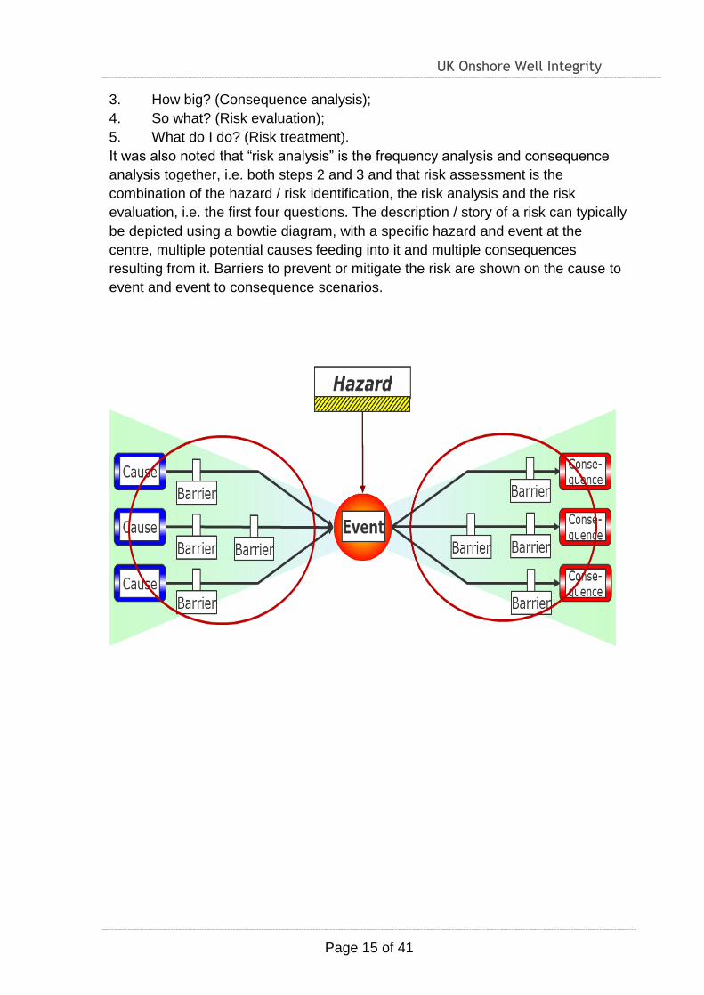
It was also noted that “risk analysis” is the frequency analysis and consequence
analysis together, i.e. both steps 2 and 3 and that risk assessment is the
combination of the hazard / risk identification, the risk analysis and the risk
evaluation, i.e. the first four questions. The description / story of a risk can typically
be depicted using a bowtie diagram, with a specific hazard and event at the
centre, multiple potential causes feeding into it and multiple consequences
resulting from it. Barriers to prevent or mitigate the risk are shown on the cause to
event and event to consequence scenarios.

UK Onshore Well Integrity
Page 16 of 41
Degradation factors, which weaken the barriers, may also be presented on the
bowtie diagram, along with controls that are in place to maintain the effectiveness
of a barrier.
Many different hazard / risk assessment techniques are available, and the correct
one(s) to apply for a particular study will depend upon the specifics of the case.
The different techniques can generally be categorised as either qualitative of
quantitative.
DNV GL has been working with a UK Operator to provide a risk analysis of the
potential for aquifer contamination associated with shale gas activity in a well.
Initially three scenarios were identified for consideration:
1. A fracture that directly links the shale gas geology to the aquifer.
2. A flow path for well fluids from the shale gas geology to the aquifer outside
the casing / cement.
3. A flow path for well fluids from the well to the aquifer through the casing and
cement
Scenario 2 was selected for detailed analysis at the present time.
UK Onshore Well Integrity
Page 17 of 41
Following a review of data available for the well and the planned frac activity, a risk
workshop was held to discuss and define the various terms of the analysis (e.g.
what would count as failure), what paths are there for fluid from the well to aquifer,
what barriers to flow exist, what causes are there for failure and what mitigating
actions could be taken. Using this information, fault trees have been prepared to
map out the different factors identified and how they are linked. There are two
trees, one for Scenario 2 occurring during the frac, the other for the scenario
occurring after frac, i.e. during production from the fractured well. Currently, work
is on-going to generate the probabilities for the base events in the fault trees. This
involves specialists in three DNV GL offices (London, Houston, Oslo) and
discussion with the operator. Once complete, this will give an estimated probability
for the potential of frac fluid or gas reaching the aquifer following the Scenario 2
flow path.
UK Onshore Well Integrity
Page 18 of 41
SECTION 6
CONTEXT
UK Onshore Well Integrity
Page 19 of 41
UK Onshore Shale Gas Well Construction and Operation
Currently there are around 2000 land drilling rigs working on oil and gas drilling
globally with many hundreds of thousands of oil and gas wells in operation. Oil and
gas wells are constructed by rotary drilling.
Before drilling can start, geologists, geophysicists and other subsurface
professionals will develop an anticipated geological model from surface. The
reservoir and petroleum engineers will determine the target formation and
requirements for the well. The drilling team will collate all the required information
to design the well to meet the objectives and ensure full life cycle integrity. Each
well is individually engineered.
Once the well has been designed an independent expert will examine the well
design to ensure that it meets Industry standards and best practices. The drilling
team will submit the well design and the associated drilling programme to the
Regulatory Authorities for the necessary consents.
The drilling process involves deploying a drill bit on a drill string that consists of 9m
long sections of steel drill pipe with sections of thicker heavy pipe at the bottom
containing any tools required for steering the drill bit, determining the position of
the drill bit and/or acquiring and transmitting downhole information.
The mechanism for drilling consists of rotating the drill bit and applying weight. The
drill bit may be steered in three dimensions to access the target zone using
downhole tools. Multiple wells are drilled from a single site to access the target
formations over a wide area with minimum surface impact.
Drilling fluid is pumped down the drill string and up the annulus between the drill
string and the drilled wellbore. The drilling fluid cools the drill bit, provides
hydraulic power and lubrication, transports the drilled cuttings to surface and
stabilises the wellbore. It also provides hydrostatic pressure to ensure that
formation fluids remain in the formation and provides a mechanism for transmitting
information between the bottom of the drill string and surface using pressure
pulses.
At surface the drill cuttings are removed and analysed to determine the formation
characteristics. The drilling fluid is treated and re-used.
Blowout preventors are installed to close off the well if the drilling fluid fails to
contain the formation fluids.
Typically many different types of formation will have to be drilled through before
the target is reached. The different formations will have different characteristics
and key properties include the rock strength, pressure within the formation, fluid
UK Onshore Well Integrity
Page 20 of 41
content and the permeability or ease at which a fluid can flow through the rock.
The variation in characteristics means that a well cannot be drilled from the
surface to a deep target in one go.
At selected points the drill bit will be pulled from the well and steel pipe called
casing will be run into the well. Like drill pipe the casing comes in 9m lengths that
are screwed together. The casing diameter will be matched to the size of the hole
drilled. The thickness of the casing will be selected to provide the burst and
collapse strength required through the life of the well, while the metallurgy of the
steel used will be selected to resist the fluids that the casing will come into contact
with during its life.
Once the casing has been run to the bottom of the well cement is pumped down
the casing and up the annulus. The cement is allowed to set in the annulus to form
a seal between the casing and the formation and to isolate the formations and
their contents from each other.
A wellhead is installed on top of the
casing to provide a mechanical seal at
surface with access to the annuli via
valves. After installation of the
wellhead the casing is pressure tested
to ensure that it is leak tight. A new drill
bit is then run and the next section of
the well is drilled.
The process of drilling a section,
acquiring information on the formations
drilled, casing, cementing, installing the
wellhead seal continues, until the
target formation is reached.
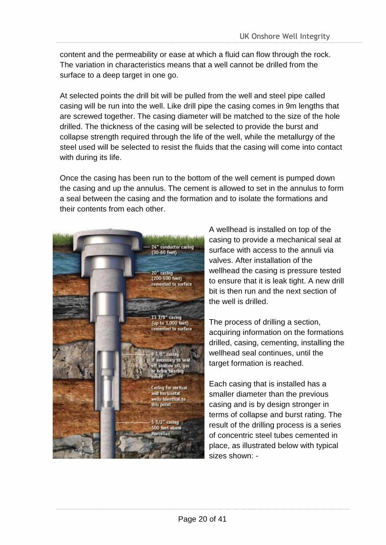
Each casing that is installed has a
smaller diameter than the previous
casing and is by design stronger in
terms of collapse and burst rating. The
result of the drilling process is a series
of concentric steel tubes cemented in
place, as illustrated below with typical
sizes shown: -
UK Onshore Well Integrity
Page 21 of 41
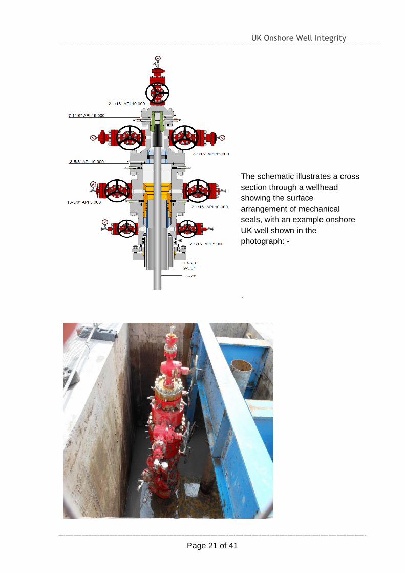
The schematic illustrates a cross
section through a wellhead
showing the surface
arrangement of mechanical
seals, with an example onshore
UK well shown in the
photograph: -
.
UK Onshore Well Integrity
Page 22 of 41
In the case of a shale gas well when the target shale has been drilled and isolated
the shale has to be hydraulically fractured to create sufficient permeability for the
gas within the shale to flow.
Without hydraulic fracturing the gas is unable to flow through the formation.
Hydraulic fracturing involves using pumps to create sufficient pressure to exceed
the fracture strength of the shale and create a fracture. Once the fracture has been
created a permeable material termed a proppant has to be pumped into the
fracture such that when the pump pressure is released the proppant remains in the
created fracture to provide the flow path. Without the proppant when the pressure
is released the weight of the rock will cause the fracture to close and the gas will
not be able to flow. Typically sand is used as a proppant.
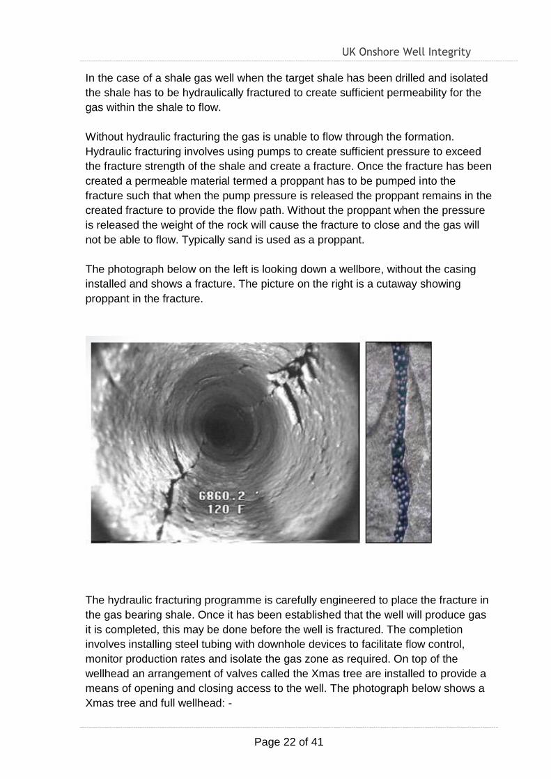
The photograph below on the left is looking down a wellbore, without the casing
installed and shows a fracture. The picture on the right is a cutaway showing
proppant in the fracture.
The hydraulic fracturing programme is carefully engineered to place the fracture in
the gas bearing shale. Once it has been established that the well will produce gas
it is completed, this may be done before the well is fractured. The completion
involves installing steel tubing with downhole devices to facilitate flow control,
monitor production rates and isolate the gas zone as required. On top of the
wellhead an arrangement of valves called the Xmas tree are installed to provide a
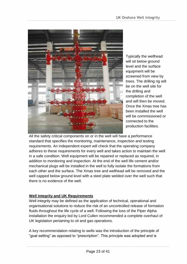
means of opening and closing access to the well. The photograph below shows a
Xmas tree and full wellhead: -
UK Onshore Well Integrity
Page 23 of 41
Typically the wellhead
will sit below ground
level and the surface
equipment will be
screened from view by
trees. The drilling rig will
be on the well site for
the drilling and
completion of the well
and will then be moved.
Once the Xmas tree has
been installed the well
will be commissioned or
connected to the
production facilities.
All the safety critical components on or in the well will have a performance
standard that specifies the monitoring, maintenance, inspection and testing
requirements. An independent expert will check that the operating company
adheres to these requirements for every well and takes action to maintain the well
in a safe condition. Well equipment will be repaired or replaced as required, in
addition to monitoring and inspection. At the end of the well life cement and/or
mechanical plugs will be installed in the well to fully isolate the formations from
each other and the surface. The Xmas tree and wellhead will be removed and the
well capped below ground level with a steel plate welded over the well such that
there is no evidence of the well.
Well Integrity and UK Requirements
Well integrity may be defined as the application of technical, operational and
organisational solutions to reduce the risk of an uncontrolled release of formation
fluids throughout the life cycle of a well. Following the loss of the Piper Alpha
installation the enquiry led by Lord Cullen recommended a complete overhaul of
UK legislation pertaining to oil and gas operations.
A key recommendation relating to wells was the introduction of the principle of
“goal setting” as opposed to “prescription”. This principle was adopted and is
UK Onshore Well Integrity
Page 24 of 41
illustrated by the following extract from Statutory Instrument 913 known as the
Well Design and Construction Regulations 1996 or “DCR”: -
“The well-operator, shall ensure that a well is so designed, modified,
commissioned, constructed, equipped, operated, maintained, suspended and
abandoned that –
(a) so far as is reasonably practicable, there can be no unplanned escape of
fluids from the well; and
(b) risks to the health and safety of persons from it or anything in it, or in the
strata to which it is connected, are as low as is reasonably practicable”
The above requirement applies to all onshore wells in Great Britain for the purpose
of exploiting naturally occurring hydrocarbons and applies throughout the whole
well life cycle. DCR requires the well operator to maintain well integrity.
The requirement “so far as is reasonably practicable” is generally termed ALARP
or “As Low As Reasonably Practicable”. Industry Standards and document what is
considered good practice and well operators must be able to demonstrate that that
they have considered these good practices and either conform or can demonstrate
why they believe that it is not practicable to conform.
Since Industry Standards and Guidelines are continually evolving in response to
learning and new technology what is considered reasonably practicable continually
evolves. Through Oil and Gas UK and the UK Onshore Operators Group the UK
was the first, and to date the only Country in the world, to publish full life cycle well
integrity guidelines.
The first issue was published in 2012, the second issue in 2014 and the next issue
is being progressed for publication in 2016.
DCR further requires the well operator to employ independent experts to check
that the above requirements are met in addition to Regulatory approvals and
oversight. The requirements for ALARP, well examination and independent
verification were first introduced in Great Britain and ensure that the UK has what
is believed to be the most robust regulatory requirements for oil and gas wells in
the world. A list of key documents pertaining to the integrity of shale gas wells can
be found in the Appendix to this paper.

UK Onshore Well Integrity
Page 25 of 41
The Role of the Well Examiner:
This role is defined under DCR 1996 Regulation 18.
The Independent well examiner is to examine information on the design and
construction of a well and the sub-surface environment including any hazards
which the geological strata and formations may contain and to examine any work
in progress, in order to provide assurance that a well is designed and constructed
properly and is adequately maintained. The purpose of examination is to provide
quality control and quality assurance that ensures, so far as is reasonably
practicable, there can be no unplanned escape of fluids from the well; and risks to
the health and safety of persons from a well are as low as is reasonably
practicable.

UK Onshore Well Integrity
Page 26 of 41
SECTION 6
DOCUMENTATION
REVIEW
UK Onshore Well Integrity
Page 27 of 41
Key Documentation Reviewed
The workgroup undertook a review of documents related to shale gas well
integrity. From the review the workgroup concluded that the key documents
relating to the management of UK well integrity were as listed below. Other
documents reviewed are listed in the Appendix.
Regulations:
Borehole Sites & Operations Regulations 1995 (BSOR)
Offshore Installations and Wells (Design & Construction etc.) Regulations
1996 (DCR)
These Regulations were produced following the enquiry led by Lord Cullen into
the Piper Alpha tragedy and form part of the UK “goal setting, with independent
verification, regulatory regime”, this approach has been recognised as global best
practice. BSOR apply only to onshore wells while DCR apply to all wells in Great
Britain for the purpose of the exploitation of naturally occurring hydrocarbons –
including shale gas. The Regulations set the requirement for well integrity as
follows: -
“The well-operator, shall ensure that a well is so designed, modified,
commissioned, constructed, equipped, operated, maintained, suspended and
abandoned that –
(a) So far as is reasonably practicable, there can be no unplanned escape of
fluids from the well; and
(b) risks to the health and safety of persons from it or anything in it, or in the
strata to which it is connected, are as low as is reasonably practicable.”
Guidelines
Oil & Gas UK (OGUK) OP095 - Well Life Cycle Integrity Guidelines, (WLCIG)
Issue 2, June 2014 (2014)
In response to the 2010 Deepwater Horizon tragedy in the Gulf of Mexico a review
of key factors relating to well control on the UK Continental Shelf was undertaken
by the Technical Review Group. A recommendation from the Technical Review
Group to form a workgroup to produce and maintain full life cycle well integrity
guidelines was taken up by the trade association OGUK. A workgroup comprising
representatives from: UK onshore and offshore well operators, UK Regulators
(HSE and DECC), well service contractors and drilling contractors was formed in
early 2011. The workgroup undertook a review of available industry standards,
recommended practices and guidelines. From this review it was determined that
full life cycle well integrity guidelines covering the scope of the DCR did not exist.
Norway had full life cycle well integrity guidelines, Norsok D-010, but this
document only covered offshore wells found on the Norwegian Continental shelf.
UK Onshore Well Integrity
Page 28 of 41
The workgroup established a working relationship with the Norwegian workgroup
with the intent of aligning UK and Norwegian as far as practicable.
The workgroup sought to document current good industry practice that could be
adopted to assist well operators in maintaining well integrity and meeting UK
Regulatory requirements. The workgroup sought to reference, rather than
duplicate, existing published documents wherever practicable. The current Issue
identifies 132 relevant documents with links where the document is publically
available. Issue 1 of the WLCIG was agreed by the UKOOG and published by
OGUK in July 2012. The document included the following: -
Summary of key UK regulatory requirements pertaining to well integrity.
Requirements of a well integrity management system.
Requirements for identifying, testing and maintaining well barriers.
Requirements to manage change.
Key requirements to establish and maintain well integrity through each stage
of the well life cycle: design and operations planning, drilling, well testing,
completion, commissioning, operation and maintenance, intervention and
workover, suspension and abandonment.
The document incorporated a feedback mechanism. The workgroup undertook
extensive communication. OGUK ran workshops to obtain feedback and input
which contributed to Issue 2 that was agreed by the UKOOG and published in
May 2014.
The workgroup undertook communication of Issue 2 and ran more workshops to
gather feedback and good practices. Issue 3 has been drafted and at February
2016 was going through review prior to anticipated publication in March 2016.
It was noted that OGUK issued and maintain other Guidelines that are relevant to
well integrity, key documents reviewed include the following: -
Guidelines for the abandonment of wells, Issue 5, July 2015.
Guidelines on competency of wells personnel, Issue 1, January 2012.
Guidelines for well operators on well examination Issue 1, November 2011.
The OGUK Guidelines also reference American Petroleum Institute (API)
documents that are widely used and considered to represent good Industry
Practice. More information on the documents reviewed is provided in the
Appendix.
UK Onshore Well Integrity
Page 29 of 41
UK Onshore Operators Group (UKOOG): UK Onshore Shale Gas Well
Guidelines
Exploration and appraisal phase - Issue 3 March 2015
In response to the seismic event recorded during the high volume hydraulic
fracturing of the first UK shale gas exploration well at Preece Hall in Lancashire
the UKOOG formed a workgroup to produce guidelines. The workgroup included
operating and service companies with input from DECC, HSE and the EA/SEPA.
The intent of the Guidelines was to document good industry practices to assist
well operators comply with UK Regulations pertaining to well integrity and
hydraulic fracturing, including fracturing fluids and flow back fluids. The workgroup
took the approach of referencing, or duplicating, the OGUK Well Life Cycle
Integrity Guidelines wherever relevant.
The Guidelines apply to the exploration and appraisal phase of shale gas
development and cover the following: -
Safety and environmental management.
Disclosure and transparency.
Regulatory requirements.
Well design and construction.
Fracturing/flowback operations.
Fracturing fluids and water management.
Minimising fugitive emissions.
As the OGUK Well Life Cycle Well Integrity Guidelines have been updated so
have the UKOOG Onshore Shale Gas Guidelines. Once Issue 3 of the OGUK
Guidelines are published UKOOG intend removing any remaining duplication in
the UK Onshore Shale Gas Guidelines such that the Onshore Guidelines simply
direct the reader to the OGUK Guidelines for all well integrity issues. The reason
for this is that it has been recognised that shale gas wells have no unique features
that cannot be addressed within the OGUK Guidelines pertaining to all oil and gas
wells in the UK.
UK Onshore Well Integrity
Page 30 of 41
SECTION 7
IMechE / IOM3
OPERATOR SURVEY

UK Onshore Well Integrity
Page 31 of 41
Background And Objectives
In September 2015 the United Kingdom Onshore Operators Group (UKOOG)
issued a UK shale gas well integrity survey to all of their member companies on
behalf of the IMechE/IOM3 shale gas well integrity workgroup. The objectives of
the questionnaire were as follows: -
o Ascertain where in the UK Companies intend drilling shale gas wells.
o Ascertain whether or not there will be conformance to the UKOOG Shale
Gas Guidelines and identify suggestions for any changes required to these
Guidelines.
o Ascertain whether or not there will be conformance to the Oil and Gas UK
(OGUK) Well Life Cycle Integrity Guidelines (WLCIG) and identify
suggestions for any changes required to these Guidelines.
o Ascertain whether or not a Well Integrity Management System that meets
the minimum requirements specified in Chapter 3 of the OGUK WLCIG is in
place and if not which minimum requirements are not being met and why.
o Identify the most significant concerns with respect to UK onshore shale gas
well integrity and why.
Responses
The survey received responses on behalf of eight companies holding the majority
of the UK licences covering areas with the potential for shale gas.
Areas in the UK for Shale Gas Activity Covered by the Survey
The companies who responded advised that they hold licences in the following
English counties: Cheshire, Lancashire, Leicestershire, Lincolnshire, Merseyside,
Nottinghamshire and Yorkshire. In addition a Company advised that they hold
licences in Scotland and intend drilling shale gas wells.
Conformance to UKOOG and OGUK Well Integrity Guidelines
The survey found that all the responding companies are using and conforming to
both the OGUK Well Integrity Guidelines and the UKOOG Shale Gas Guidelines.
In addition all the companies either already have, or are in the process of
finalising, well integrity management systems that conform to the Guidance
contained in the OGUK Well Integrity Guidelines.
Suggested Changes to the UKOOG Shale Gas Guidelines
A number of companies commented that the OGUK Well Integrity Guidelines are
the primary guide for onshore and offshore oil and gas well integrity and
suggested that the UKOOG Shale Gas Guidelines could be simplified by having
one statement to refer to the OGUK Well Integrity Guidelines for all Guidance on
well integrity. Currently the UKOOG Shale Gas Guidelines refer to the OGUK
Guidelines, while also including extracts and referencing specific sections of the
OGUK Guidelines.
UK Onshore Well Integrity
Page 32 of 41
One Company highlighted that the UKOOG Shale Gas Guidelines reference the
OGUK Guidelines for Well Integrity and Well Abandonment, however shale gas
formations typically have extremely low permeability and therefore some of the
requirements in the OGUK Guidelines may be inappropriate: inflow testing and the
length of annular cement required were given as examples. Rather than each
shale gas well operator having to undertake an individual risk assessment it was
suggested that generic issues be identified and an agreed position documented in
the Shale Gas Guidelines. As an alternative the OGUK Guidelines could be
updated to address generic issues.
Suggested Changes to the OGUK Well Integrity Guidelines and/or Well
Abandonment Guidelines
Further to the suggestions to refer to the OGUK Guidelines for all onshore and
offshore oil and gas well integrity guidance it was suggested that onshore well
operators should have greater input to the OGUK well integrity workgroup to
ensure that the Guidelines fully address good practices relevant to onshore shale
gas wells.
Most Significant Concerns Regarding UK Onshore Shale Gas Integrity
Seven companies provided feedback on key concerns. The most common
concern was public perception; reference the following quote from the feedback:
“The understandably low level of knowledge of well integrity issues amongst the
general public coupled with targeted misinformation from those groups opposed to
shale gas development has led to undue concerns/fears around this issue.
Industry and competent bodies such as the EA, HSE and OGA/DECC need to
robustly defend current regulatory practice.”
UK Onshore Well Integrity
Page 33 of 41
SECTION 8
WORK IN PROGRESS
UK Onshore Well Integrity
Page 34 of 41
On-going Studies:
It is recognised that this topic is fluid and other studies are being performed at this
time. The following indicate some of the work being done.
OGUK - Well Life Cycle Integrity Guidelines
As detailed in the documentation review Issue 3 of the above Guidelines was
being finalised in parallel with the development of this paper. Onshore well
operators had provided input to the development of Issue 3 and indeed the
process of developing this paper had encouraged additional input from onshore
well operators. UKOOG endorsed the draft Issue 3 in January 2016. At the same
time UKOOG agreed to simplify the UK Shale Gas Guidelines to remove any
duplication with Issue 3 of the OGUK Well Integrity Guidelines thereby addressing
a key piece of feedback from the well integrity survey. UKOOG further supported
communication of Issue 3 and input to Issue 4 of the OGUK Well Integrity
Guidelines. At the beginning of February 2016 Issue 3 of the OGUK Well Integrity
Guidelines was being finalised for publication in March 2016. Thereafter the intent
was to communicate Issue 3, obtain feedback on Issue 3 and develop Issue 4.
The IMechE/IOM3 shale gas well integrity workgroup commend the above
approach.
Emissions Monitoring
While the review of UK onshore shale gas well integrity was on-going the ReFINE
group were undertaking sampling of emissions from historic onshore UK gas and
oil wells. Reports on this work were published in January 2016: Boothroyd, I.M., et
al., Fugitive emissions of methane from abandoned, decommissioned oil and gas
wells, Sci Total Environ (2015), http://dx.doi.org/10.1016/j.scitotenv.2015.12.096
The workgroup did not have sufficient time to cover this new work in this paper.
Environment Agency Consultation
The Environment Agency regulates the environmental aspects of the onshore oil
and gas industry in England through the Environmental Permitting Regulations
(EPR) 2010.
There is a Memorandum of Understanding between the Environment Agency and
the HSE [Ref 3], to ensure effective coordination of the regulation of plant,
processes and substances and measures to protect people and the environment,
which are subject to regulation by both the Environment Agency and the HSE. An
onshore operator must acquire environmental permits from the EA prior to carrying
out any oil and/or gas exploration or appraisal activities, which include the
following:
• the management of extractive waste, whether or not this involves a waste
facility (as a mining waste operation)
UK Onshore Well Integrity
Page 35 of 41
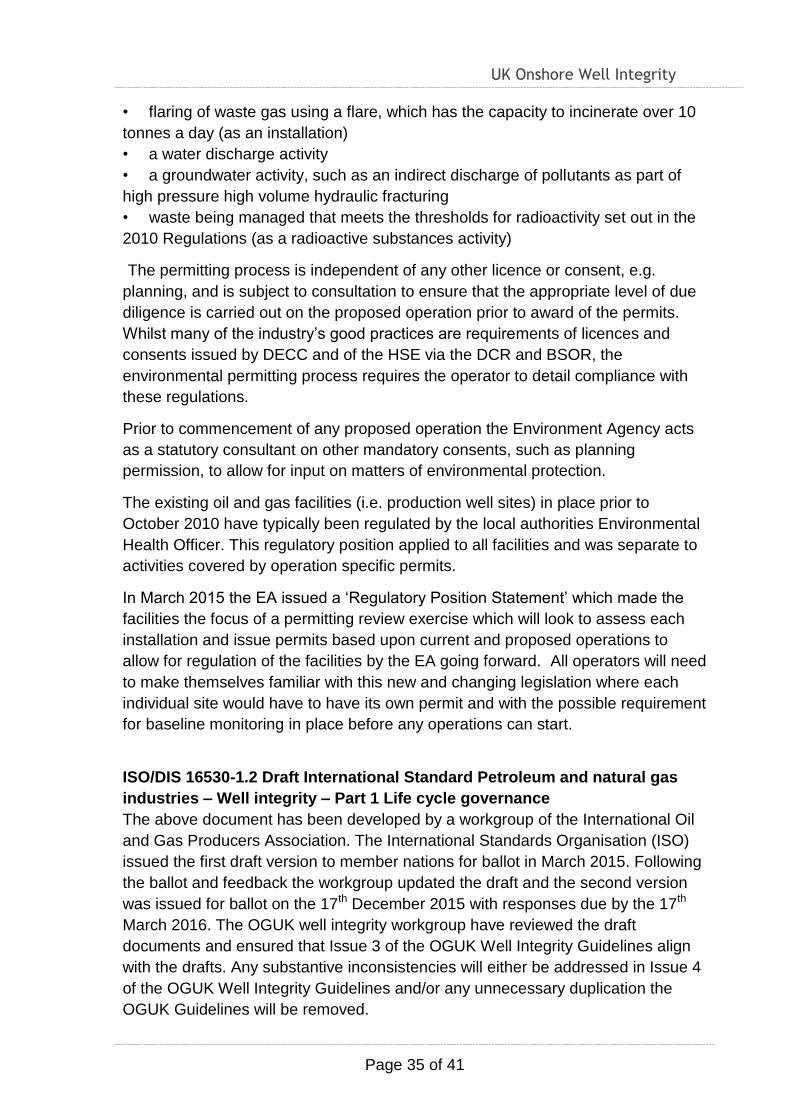
• flaring of waste gas using a flare, which has the capacity to incinerate over 10
tonnes a day (as an installation)
• a water discharge activity
• a groundwater activity, such as an indirect discharge of pollutants as part of
high pressure high volume hydraulic fracturing
• waste being managed that meets the thresholds for radioactivity set out in the
2010 Regulations (as a radioactive substances activity)
The permitting process is independent of any other licence or consent, e.g.
planning, and is subject to consultation to ensure that the appropriate level of due
diligence is carried out on the proposed operation prior to award of the permits.
Whilst many of the industry’s good practices are requirements of licences and
consents issued by DECC and of the HSE via the DCR and BSOR, the
environmental permitting process requires the operator to detail compliance with
these regulations.
Prior to commencement of any proposed operation the Environment Agency acts
as a statutory consultant on other mandatory consents, such as planning
permission, to allow for input on matters of environmental protection.
The existing oil and gas facilities (i.e. production well sites) in place prior to
October 2010 have typically been regulated by the local authorities Environmental
Health Officer. This regulatory position applied to all facilities and was separate to
activities covered by operation specific permits.
In March 2015 the EA issued a ‘Regulatory Position Statement’ which made the
facilities the focus of a permitting review exercise which will look to assess each
installation and issue permits based upon current and proposed operations to
allow for regulation of the facilities by the EA going forward. All operators will need
to make themselves familiar with this new and changing legislation where each
individual site would have to have its own permit and with the possible requirement
for baseline monitoring in place before any operations can start.
ISO/DIS 16530-1.2 Draft International Standard Petroleum and natural gas
industries – Well integrity – Part 1 Life cycle governance
The above document has been developed by a workgroup of the International Oil
and Gas Producers Association. The International Standards Organisation (ISO)
issued the first draft version to member nations for ballot in March 2015. Following
the ballot and feedback the workgroup updated the draft and the second version
was issued for ballot on the 17th December 2015 with responses due by the 17th
March 2016. The OGUK well integrity workgroup have reviewed the draft
documents and ensured that Issue 3 of the OGUK Well Integrity Guidelines align
with the drafts. Any substantive inconsistencies will either be addressed in Issue 4
of the OGUK Well Integrity Guidelines and/or any unnecessary duplication the
OGUK Guidelines will be removed.
UK Onshore Well Integrity
Page 36 of 41
SECTION 9
APPENDIX

UK Onshore Well Integrity
Page 37 of 41
Additional Documents Reviewed
The following documents were reviewed by the workgroup, in addition to the
key documents, listed above.
Document Title and Comments
No. 1 Managing for Health and Safety: HSG65 Third edition 2013
This document explains the Plan, Do, Check, Act approach and shows how it can help achieve a balance between the systems and behavioural aspects of management. Health and safety management treated as an integral part of good management, rather than as a stand-alone system. The workgroup considered that this document was not specifically related to well integrity.
No. 2 ISO/TS 16530-2:2014 Well integrity -- Part 2: Well integrity for the operational phase This document provides requirements and methods to the oil and gas industry to manage wells during the operational phase. The operational phase is considered to extend from handover of the well after construction, to handover prior to abandonment. The workgroup view was that the Oil and Gas UK Well Integrity Guidelines by and large addressed these activities.
No.3 Oil & Gas UK: Guidelines for well operators on well examination, Issue 1, November 2011
Well examination is a British Regulatory requirement for independent assurance of well design, construction and maintenance throughout the well life cycle. These Guidelines document good Industry Practice for well examination to meet the Regulatory requirements. The Guidelines address the findings from HSE inspections of well examination.
These Guidelines were in the process of being updated to address legislative changes for offshore wells following the issue of the Offshore Safety Case Regs 2015 on 19
th July 2015.
No.4 Oil & Gas UK: Guidelines on competency of wells personnel, Issue 1, January 2012
These Guidelines document the Regulatory requirements for competency, competency management system requirements and competency assurance for well personnel. An associated document provides example competency profiles for some core roles.
No.5 Norsok: Standard D-010 well integrity in drilling and well operations, Rev 4, June 2013
This document contains detailed Guidance that is used by Norwegian well operators as a “standard”. The document is widely referenced but is written for wells on the Norwegian Continental shelf and therefore does not address specific considerations for land wells.
No. 6 Norwegian OLF 117: Recommended guidelines for well integrity, Rev 6, June 2011
This document provides a Norwegian view on well integrity training, well integrity management system, sustained casing pressure management and well categorisation.
UK Onshore Well Integrity
Page 38 of 41
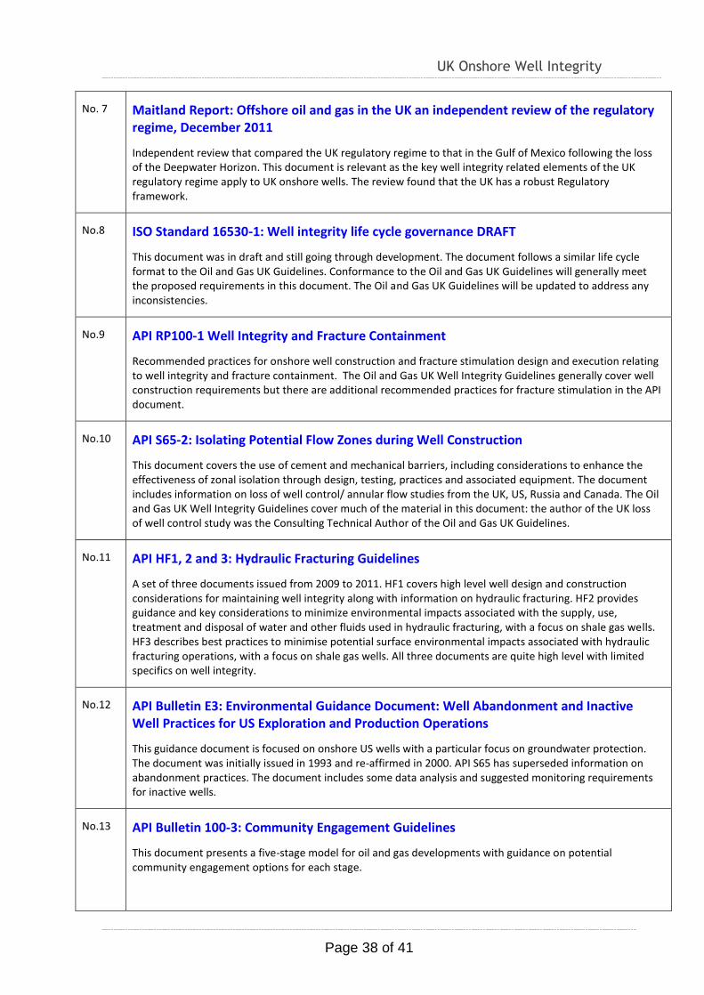
No. 7 Maitland Report: Offshore oil and gas in the UK an independent review of the regulatory regime, December 2011
Independent review that compared the UK regulatory regime to that in the Gulf of Mexico following the loss of the Deepwater Horizon. This document is relevant as the key well integrity related elements of the UK regulatory regime apply to UK onshore wells. The review found that the UK has a robust Regulatory framework.
No.8 ISO Standard 16530-1: Well integrity life cycle governance DRAFT
This document was in draft and still going through development. The document follows a similar life cycle format to the Oil and Gas UK Guidelines. Conformance to the Oil and Gas UK Guidelines will generally meet the proposed requirements in this document. The Oil and Gas UK Guidelines will be updated to address any inconsistencies.
No.9 API RP100-1 Well Integrity and Fracture Containment
Recommended practices for onshore well construction and fracture stimulation design and execution relating to well integrity and fracture containment. The Oil and Gas UK Well Integrity Guidelines generally cover well construction requirements but there are additional recommended practices for fracture stimulation in the API document.
No.10 API S65-2: Isolating Potential Flow Zones during Well Construction
This document covers the use of cement and mechanical barriers, including considerations to enhance the effectiveness of zonal isolation through design, testing, practices and associated equipment. The document includes information on loss of well control/ annular flow studies from the UK, US, Russia and Canada. The Oil and Gas UK Well Integrity Guidelines cover much of the material in this document: the author of the UK loss of well control study was the Consulting Technical Author of the Oil and Gas UK Guidelines.
No.11 API HF1, 2 and 3: Hydraulic Fracturing Guidelines
A set of three documents issued from 2009 to 2011. HF1 covers high level well design and construction considerations for maintaining well integrity along with information on hydraulic fracturing. HF2 provides guidance and key considerations to minimize environmental impacts associated with the supply, use, treatment and disposal of water and other fluids used in hydraulic fracturing, with a focus on shale gas wells. HF3 describes best practices to minimise potential surface environmental impacts associated with hydraulic fracturing operations, with a focus on shale gas wells. All three documents are quite high level with limited specifics on well integrity.
No.12 API Bulletin E3: Environmental Guidance Document: Well Abandonment and Inactive Well Practices for US Exploration and Production Operations
This guidance document is focused on onshore US wells with a particular focus on groundwater protection. The document was initially issued in 1993 and re-affirmed in 2000. API S65 has superseded information on abandonment practices. The document includes some data analysis and suggested monitoring requirements for inactive wells.
No.13 API Bulletin 100-3: Community Engagement Guidelines
This document presents a five-stage model for oil and gas developments with guidance on potential community engagement options for each stage.
UK Onshore Well Integrity
Page 39 of 41
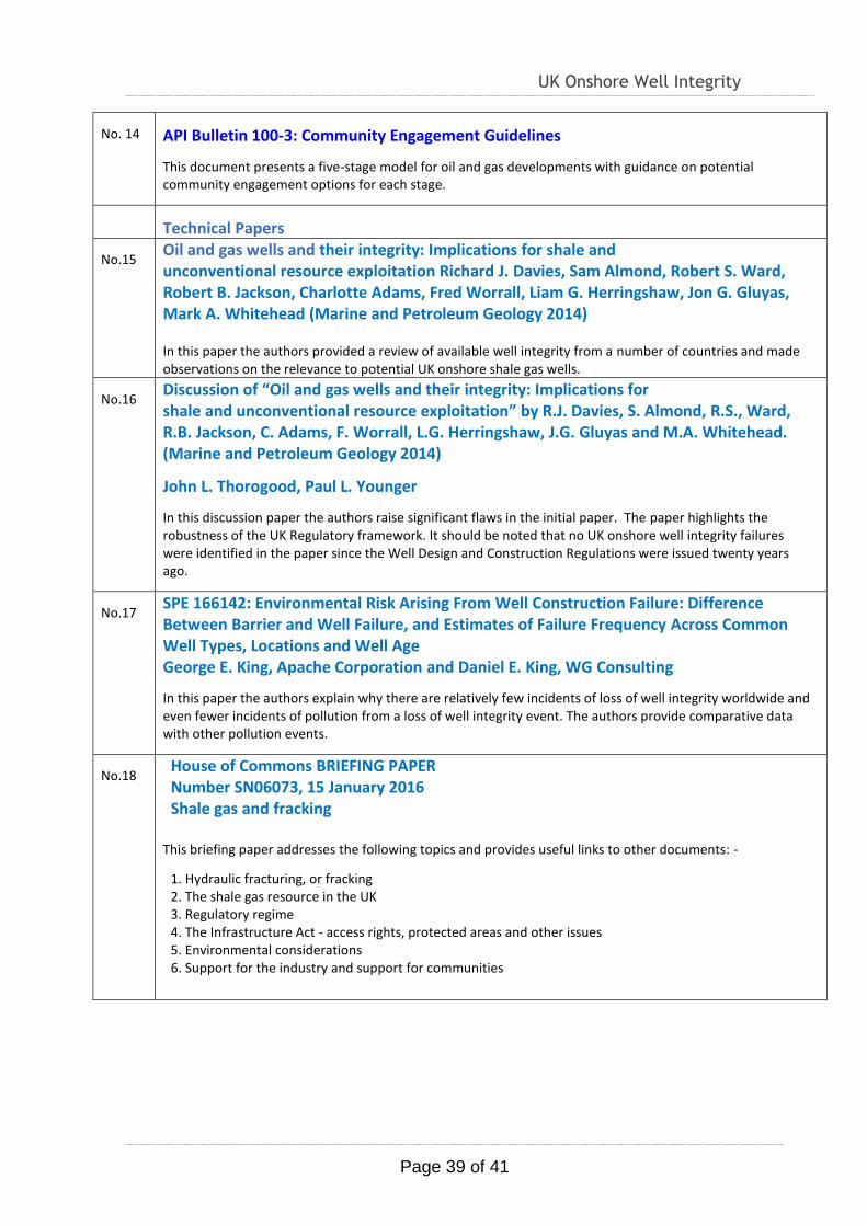
No. 14 API Bulletin 100-3: Community Engagement Guidelines
This document presents a five-stage model for oil and gas developments with guidance on potential community engagement options for each stage.
Technical Papers
No.15 Oil and gas wells and their integrity: Implications for shale and unconventional resource exploitation Richard J. Davies, Sam Almond, Robert S. Ward, Robert B. Jackson, Charlotte Adams, Fred Worrall, Liam G. Herringshaw, Jon G. Gluyas, Mark A. Whitehead (Marine and Petroleum Geology 2014) In this paper the authors provided a review of available well integrity from a number of countries and made observations on the relevance to potential UK onshore shale gas wells.
No.16 Discussion of “Oil and gas wells and their integrity: Implications for shale and unconventional resource exploitation” by R.J. Davies, S. Almond, R.S., Ward, R.B. Jackson, C. Adams, F. Worrall, L.G. Herringshaw, J.G. Gluyas and M.A. Whitehead. (Marine and Petroleum Geology 2014)
John L. Thorogood, Paul L. Younger
In this discussion paper the authors raise significant flaws in the initial paper. The paper highlights the robustness of the UK Regulatory framework. It should be noted that no UK onshore well integrity failures were identified in the paper since the Well Design and Construction Regulations were issued twenty years ago.
No.17 SPE 166142: Environmental Risk Arising From Well Construction Failure: Difference Between Barrier and Well Failure, and Estimates of Failure Frequency Across Common Well Types, Locations and Well Age George E. King, Apache Corporation and Daniel E. King, WG Consulting
In this paper the authors explain why there are relatively few incidents of loss of well integrity worldwide and even fewer incidents of pollution from a loss of well integrity event. The authors provide comparative data with other pollution events.
No.18 House of Commons BRIEFING PAPER Number SN06073, 15 January 2016 Shale gas and fracking
This briefing paper addresses the following topics and provides useful links to other documents: -
1. Hydraulic fracturing, or fracking 2. The shale gas resource in the UK 3. Regulatory regime 4. The Infrastructure Act - access rights, protected areas and other issues 5. Environmental considerations 6. Support for the industry and support for communities
UK Onshore Well Integrity
Page 40 of 41
GLOSSARY
UK Onshore Well Integrity
Page 41 of 41
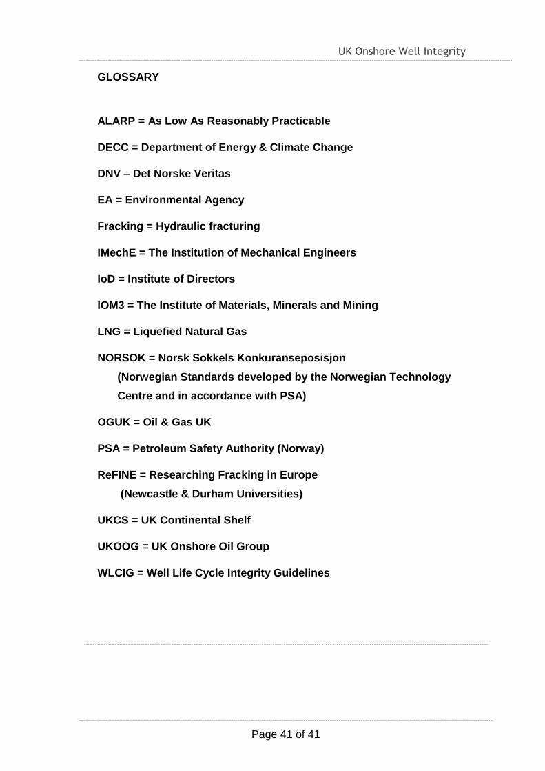
GLOSSARY
ALARP = As Low As Reasonably Practicable
DECC = Department of Energy & Climate Change
DNV – Det Norske Veritas
EA = Environmental Agency
Fracking = Hydraulic fracturing
IMechE = The Institution of Mechanical Engineers
IoD = Institute of Directors
IOM3 = The Institute of Materials, Minerals and Mining
LNG = Liquefied Natural Gas
NORSOK = Norsk Sokkels Konkuranseposisjon
(Norwegian Standards developed by the Norwegian Technology
Centre and in accordance with PSA)
OGUK = Oil & Gas UK
PSA = Petroleum Safety Authority (Norway)
ReFINE = Researching Fracking in Europe
(Newcastle & Durham Universities)
UKCS = UK Continental Shelf
UKOOG = UK Onshore Oil Group
WLCIG = Well Life Cycle Integrity Guidelines