Embed Size (px)
Citation preview
ISSN: 2455-2631 © June 2017 IJSDR | Volume 2, Issue 6
IJSDR1706051 International Journal of Scientific Development and Research (IJSDR) www.ijsdr.org 340
An improved grid-voltage regulation as a statcom by
using iUPQC
JAGANMOHANRAO.TARRA1, K.S SUNEEL GOUTHAM
2, A.JAGANNADHAM
3
Assistant Professor
Electrical& Electronics Engineering,
AITAM, Tekkali, Srikakulam, A.P India
ABSTRACT: This paper presents a simplified control technique for a dual three-phase topology of a unified power quality
conditioner—iUPQC. The iUPQC is composed of two active filters, a series active filter and a shunt active filter (parallel
active filter), used to eliminate harmonics and unbalances.. By using this controller, beyond the conventional UPQC power
quality features, including voltage sag/swell compensation, the iUPQC will also provide reactive power support to regulate not
only the load-bus voltage but also the voltage at the grid-side bus. In other words, the iUPQC will work as a static synchronous
compensator (STATCOM) at the grid side, while providing also the conventional UPQC compensations at the load or
microgrid side.
Index Terms—iUPQC, microgrids, power quality, static synchronous compensator (STATCOM), unified power quality
conditioner (UPQC).
I. INTRODUCTION
Certainly, power-electronics devices have brought about great technological improvements. However, the increasing
number of power-electronics-driven loads used generally in the industry has brought about uncommon power quality problems. In
contrast, power-electronics-driven loads generally require ideal sinusoidal supply voltage in order to function properly, whereas
they are the most responsible ones for abnormal harmonic currents level in the distribution system. In this scenario, devices that
can mitigate these drawbacks have been developed over the years. Some of the solutions involve a flexible compensator, known
as the unified power quality conditioner (UPQC) and the static synchronous compensator (STATCOM).
The power circuit of a UPQC consists of a combination of a shunt active filter and a series active filter connected in a back-to-
back configuration. This combination allows the simultaneous compensation of the load current and the supply voltage, so that
the compensated current drawn from the grid and the compensated supply voltage delivered to the load are kept balanced and
sinusoidal. The dual topology of the UPQC, i.e., the IUPQC, was presented in the shunt active filter behaves as an ac-voltage
source and the series one as an ac-current source, both at the fundamental frequency. This is a key point to better design the
control gains, as well as to optimize the LCL filter of the power converters, which allows improving significantly the overall
performance of the compensator.
The STATCOM has been used widely in transmission networks to regulate the voltage by means of dynamic reactive power
compensation. Nowadays, the STATCOM is largely used for voltage regulation, whereas the UPQC and the IUPQC have been
selected as solution for more specific applications. Moreover, these last ones are used only in particular cases, where their
relatively high costs are justified by the power quality improvement it can provide, which would be unfeasible by using
conventional solutions. By joining the extra functionality like a STATCOM in the IUPQC device, a wider scenario of
applications can be reached, particularly in case of distributed generation in smart grids and as the coupling device in grid-tied
micro grids. In the performance of the IUPQC and the UPQC was
ISSN: 2455-2631 © June 2017 IJSDR | Volume 2, Issue 6
IJSDR1706051 International Journal of Scientific Development and Research (IJSDR) www.ijsdr.org 341
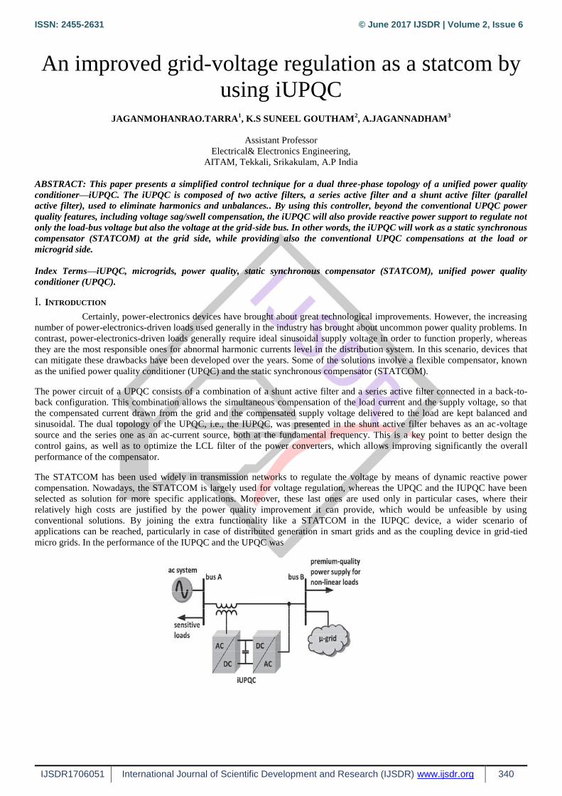
The provision of both DSTATCOM and DVR can control the power quality of the source current and the load bus voltage. In
addition, if the DVR and STATCOM are connected on the DC side, the DC bus voltage can be regulated by the shunt connected
DSTATCOM while the DVR supplies the required energy to the load in case of the transient disturbances in source voltage. The
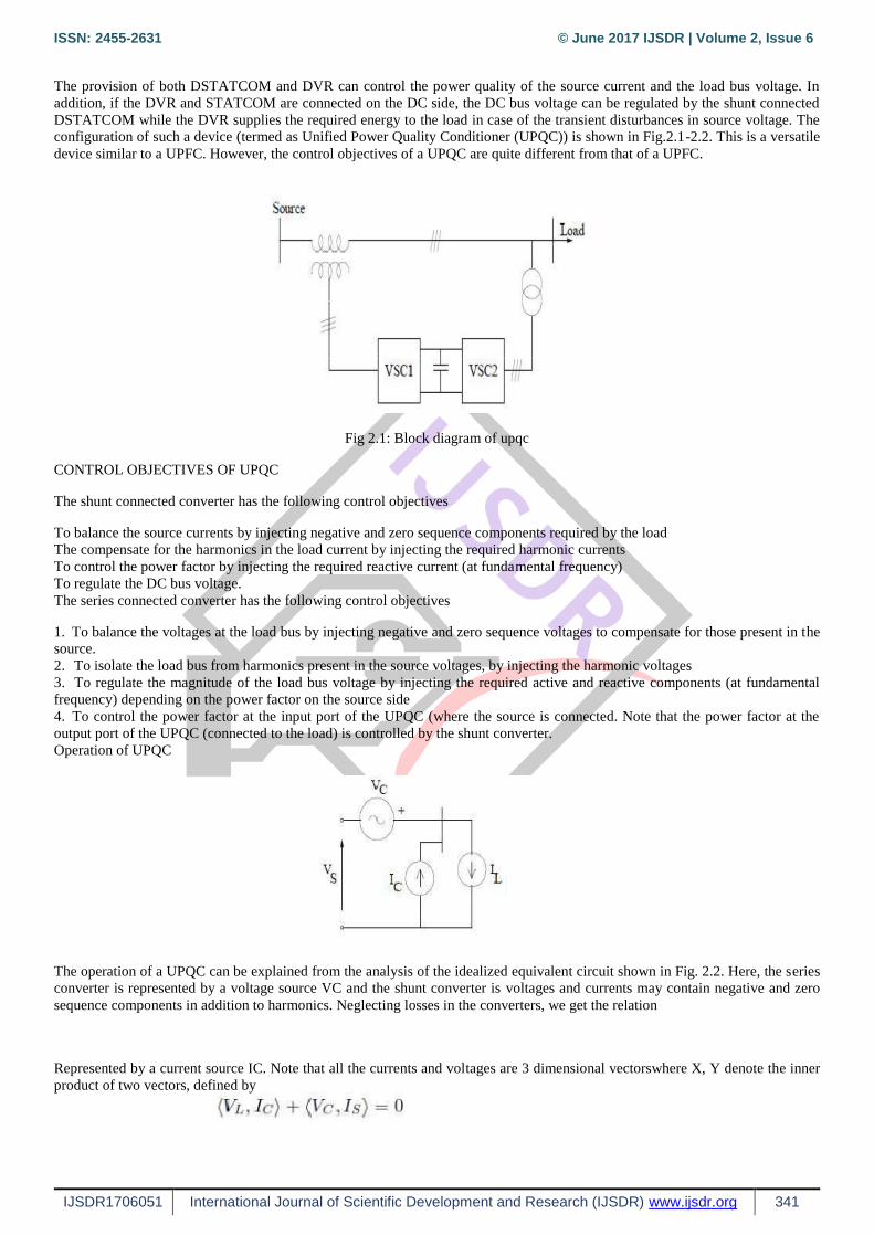
configuration of such a device (termed as Unified Power Quality Conditioner (UPQC)) is shown in Fig.2.1-2.2. This is a versatile
device similar to a UPFC. However, the control objectives of a UPQC are quite different from that of a UPFC.
Fig 2.1: Block diagram of upqc
CONTROL OBJECTIVES OF UPQC
The shunt connected converter has the following control objectives
To balance the source currents by injecting negative and zero sequence components required by the load
The compensate for the harmonics in the load current by injecting the required harmonic currents
To control the power factor by injecting the required reactive current (at fundamental frequency)
To regulate the DC bus voltage.
The series connected converter has the following control objectives
1. To balance the voltages at the load bus by injecting negative and zero sequence voltages to compensate for those present in the
source.
2. To isolate the load bus from harmonics present in the source voltages, by injecting the harmonic voltages
3. To regulate the magnitude of the load bus voltage by injecting the required active and reactive components (at fundamental
frequency) depending on the power factor on the source side
4. To control the power factor at the input port of the UPQC (where the source is connected. Note that the power factor at the
output port of the UPQC (connected to the load) is controlled by the shunt converter.
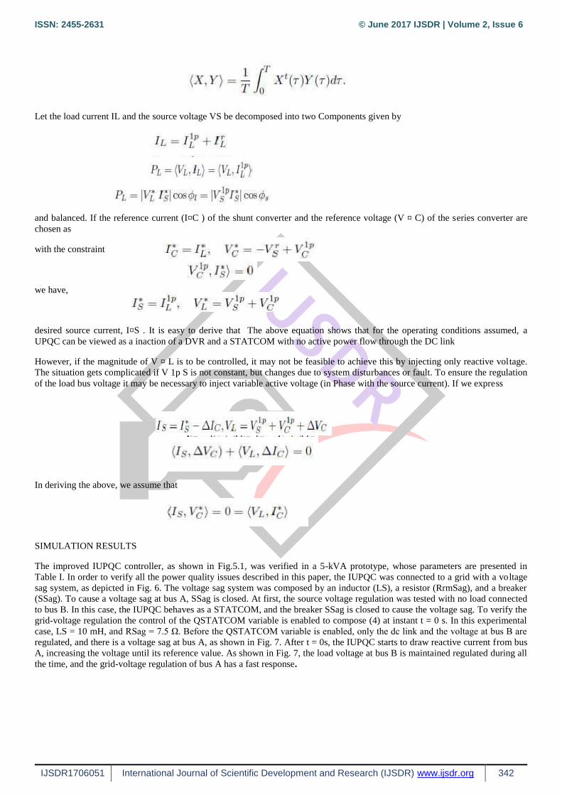
Operation of UPQC
The operation of a UPQC can be explained from the analysis of the idealized equivalent circuit shown in Fig. 2.2. Here, the series
converter is represented by a voltage source VC and the shunt converter is voltages and currents may contain negative and zero
sequence components in addition to harmonics. Neglecting losses in the converters, we get the relation
Represented by a current source IC. Note that all the currents and voltages are 3 dimensional vectorswhere X, Y denote the inner
product of two vectors, defined by
ISSN: 2455-2631 © June 2017 IJSDR | Volume 2, Issue 6
IJSDR1706051 International Journal of Scientific Development and Research (IJSDR) www.ijsdr.org 342
Let the load current IL and the source voltage VS be decomposed into two Components given by
and balanced. If the reference current (I¤C ) of the shunt converter and the reference voltage (V ¤ C) of the series converter are
chosen as
with the constraint
we have,
desired source current, I¤S . It is easy to derive that The above equation shows that for the operating conditions assumed, a
UPQC can be viewed as a inaction of a DVR and a STATCOM with no active power flow through the DC link
However, if the magnitude of V ¤ L is to be controlled, it may not be feasible to achieve this by injecting only reactive voltage.
The situation gets complicated if V 1p S is not constant, but changes due to system disturbances or fault. To ensure the regulation
of the load bus voltage it may be necessary to inject variable active voltage (in Phase with the source current). If we express
In deriving the above, we assume that
SIMULATION RESULTS
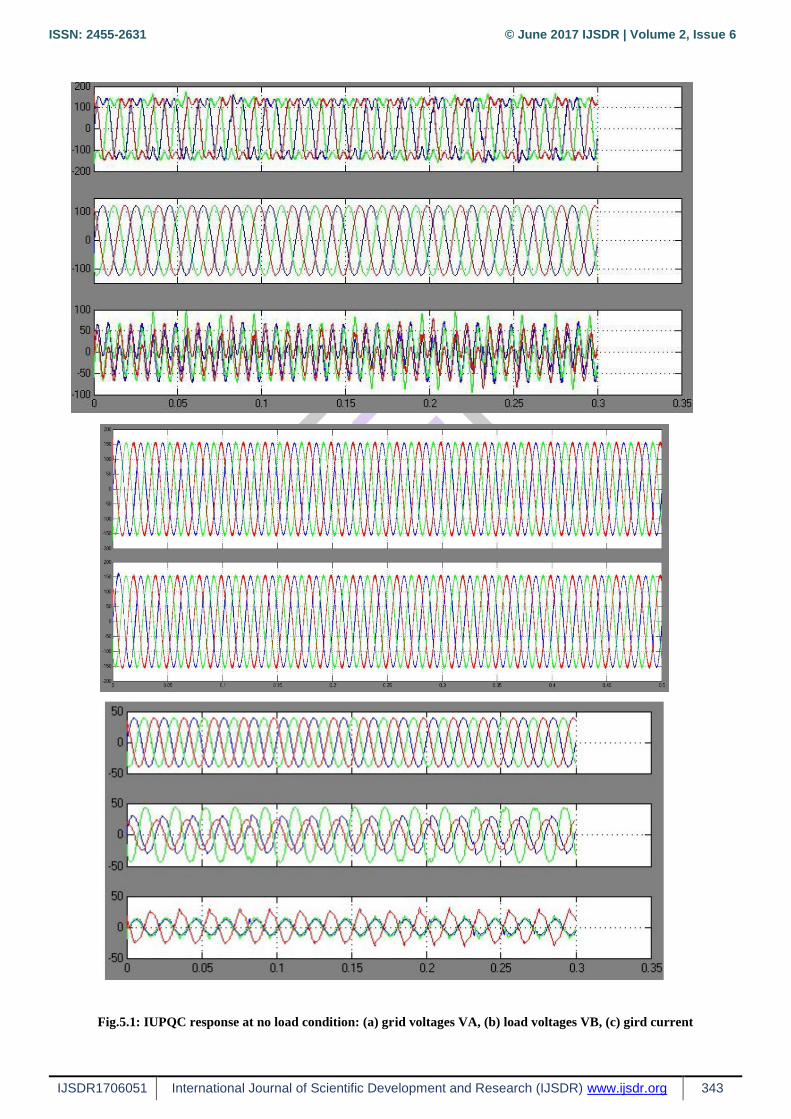
The improved IUPQC controller, as shown in Fig.5.1, was verified in a 5-kVA prototype, whose parameters are presented in
Table I. In order to verify all the power quality issues described in this paper, the IUPQC was connected to a grid with a voltage
sag system, as depicted in Fig. 6. The voltage sag system was composed by an inductor (LS), a resistor (RrmSag), and a breaker
(SSag). To cause a voltage sag at bus A, SSag is closed. At first, the source voltage regulation was tested with no load connected
to bus B. In this case, the IUPQC behaves as a STATCOM, and the breaker SSag is closed to cause the voltage sag. To verify the
grid-voltage regulation the control of the QSTATCOM variable is enabled to compose (4) at instant t = 0 s. In this experimental
case, LS = 10 mH, and RSag = 7.5 Ω. Before the QSTATCOM variable is enabled, only the dc link and the voltage at bus B are
regulated, and there is a voltage sag at bus A, as shown in Fig. 7. After t = 0s, the IUPQC starts to draw reactive current from bus
A, increasing the voltage until its reference value. As shown in Fig. 7, the load voltage at bus B is maintained regulated during all
the time, and the grid-voltage regulation of bus A has a fast response.
ISSN: 2455-2631 © June 2017 IJSDR | Volume 2, Issue 6
IJSDR1706051 International Journal of Scientific Development and Research (IJSDR) www.ijsdr.org 343
Fig.5.1: IUPQC response at no load condition: (a) grid voltages VA, (b) load voltages VB, (c) gird current
ISSN: 2455-2631 © June 2017 IJSDR | Volume 2, Issue 6
IJSDR1706051 International Journal of Scientific Development and Research (IJSDR) www.ijsdr.org 344
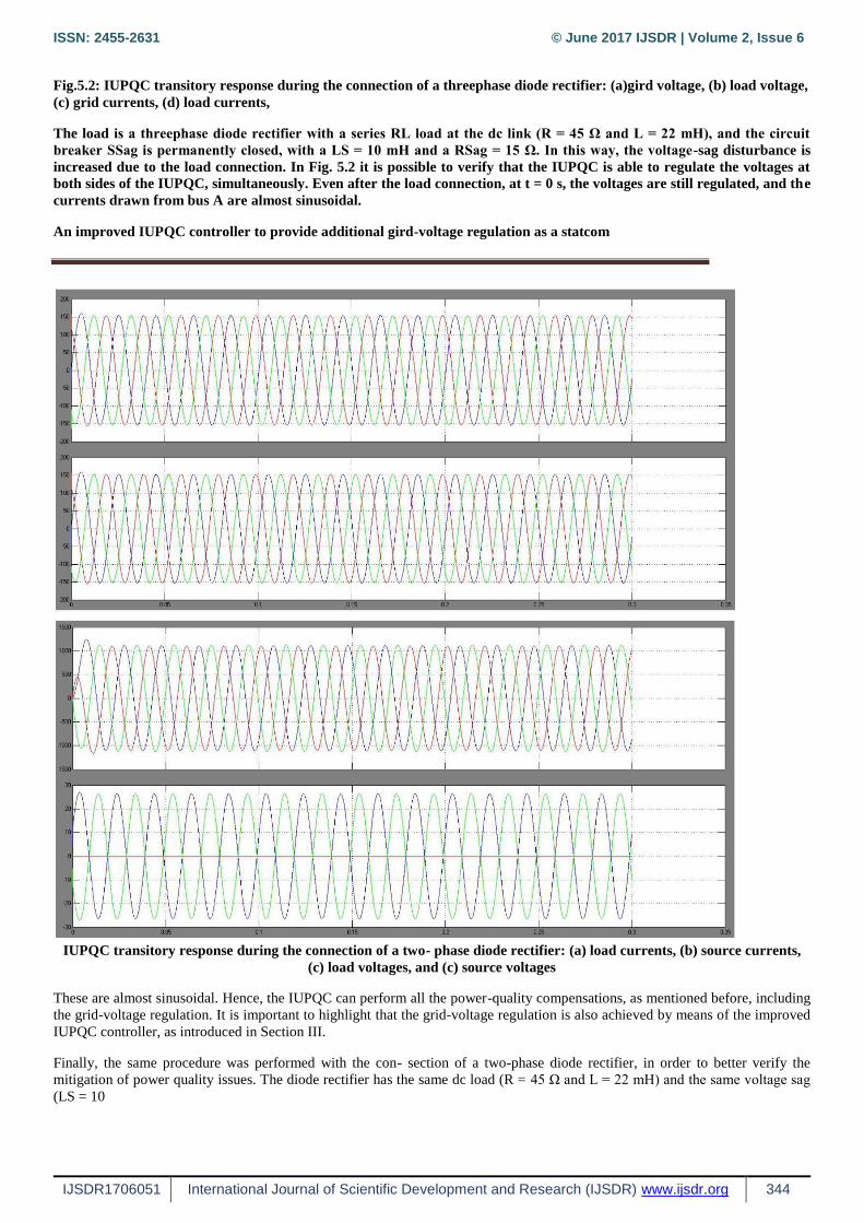
Fig.5.2: IUPQC transitory response during the connection of a threephase diode rectifier: (a)gird voltage, (b) load voltage,
(c) grid currents, (d) load currents,
The load is a threephase diode rectifier with a series RL load at the dc link (R = 45 Ω and L = 22 mH), and the circuit
breaker SSag is permanently closed, with a LS = 10 mH and a RSag = 15 Ω. In this way, the voltage-sag disturbance is
increased due to the load connection. In Fig. 5.2 it is possible to verify that the IUPQC is able to regulate the voltages at
both sides of the IUPQC, simultaneously. Even after the load connection, at t = 0 s, the voltages are still regulated, and the
currents drawn from bus A are almost sinusoidal.
An improved IUPQC controller to provide additional gird-voltage regulation as a statcom
IUPQC transitory response during the connection of a two- phase diode rectifier: (a) load currents, (b) source currents,
(c) load voltages, and (c) source voltages
These are almost sinusoidal. Hence, the IUPQC can perform all the power-quality compensations, as mentioned before, including
the grid-voltage regulation. It is important to highlight that the grid-voltage regulation is also achieved by means of the improved
IUPQC controller, as introduced in Section III.
Finally, the same procedure was performed with the con- section of a two-phase diode rectifier, in order to better verify the
mitigation of power quality issues. The diode rectifier has the same dc load (R = 45 Ω and L = 22 mH) and the same voltage sag
(LS = 10
ISSN: 2455-2631 © June 2017 IJSDR | Volume 2, Issue 6
IJSDR1706051 International Journal of Scientific Development and Research (IJSDR) www.ijsdr.org 345
An improved IUPQC controller to provide additional gird-voltage regulation as a statcom mH and RrmSag = 15 Ω). Fig.5.3
depicts the transitory response of the load connection. Despite the two- phase load currents, after the load connection at t = 0 s,
the three-phase current drained from the grid has a reduced unbalanced component. Likewise, the unbalance in the voltage at bus
A is negligible. Unfortunately, the voltage at bus B has higher unbalance content. These components could be mitigated if the
shunt compensator works as an ideal voltage source, i.e., if the filter inductor could be eliminated. In this case, the unbalanced
current of the load could be supplied by the shunt converter, and the voltage at the bus B could be exactly the voltage synthesized
by the shunt converter. Therefore, without filter inductor, there would be no unbalance voltage drop in it and the voltage at bus B
would remain balanced. However, in a practical case, this inductor cannot be eliminated, and an improved PWM control to
compensate voltage unbalances, as mentioned in Section III, is necessary
CONCLUSION
In the improved IUPQC controller, the currents synthesized by the series converter are determined by the average active power of
the load and the active power to provide the dc-link voltage regulation, together with an average reactive power to regulate the
grid-bus voltage. In this manner, in addition to all the power-quality compensation features of a conventional UPQC or an
IUPQC, this improved controller also mimics a STATCOM to the grid bus. This new feature enhances the applicability of the
IUPQC and provides new solutions in future scenarios involving smart grids and microgrids, including distributed generation and
energy storage systems to better deal with the inherent variability of renewable resources such as solar and wind power.
Moreover, the improved IUPQC controller may justify the costs and promotes the IUPQC applicability in power quality issues of
critical systems, where it is necessary not only an IUPQC or a STATCOM, but both, simultaneously. Despite the addition of one
more power-quality compensation feature, the grid-voltage regulation reduces the inner-loop circulating power inside the IUPQC,
which would allow lower power rating for the series converter. The experimental results verified the improved IUPQC goals. The
grid-voltage regulation was achieved with no load, as well as when supplying a three-phase nonlinear load. These results have
demonstrated a suitable performance of voltage regulation at both sides of the IUPQC, even while compensating harmonic
current and voltage imbalances.
REFERENCES
[1] K. Karanki, G. Geddada, M. K. Mishra, and B. K. Kumar, “A modified three-phase four-wire UPQC topology with reduced
DC-link voltage rating,” IEEE Trans. Ind. Electron., vol. 60, no. 9, pp. 3555–3566, Sep. 2013.
[2] V. Khadkikar and A. Chandra, “A new control philosophy for a unified power quality conditioner (UPQC) to coordinate
load-reactive power demand between shunt and series inverters,” IEEE Trans. Power Del., vol. 23, no. 4, pp. 2522–2534, Oct.
2008.
[3] K. H. Kwan, P. L. So, and Y. C. Chu, “An output regulation-based unified power quality conditioner with Kalman filters,”
IEEE Trans. Ind. Electron., vol. 59, no. 11, pp. 4248–4262, Nov. 2012.
[4] A. Mokhtatpour and H. A. Shayanfar, “Power quality compensation as well as power flow control using of unified power
quality conditioner,” in Proc. APPEEC, 2011, pp. 1–4.
[5] J. A. Munoz et al., “Design of a discrete-time linear control strategy for a multicell UPQC,” IEEE Trans. Ind. Electron., vol.
59, no. 10, pp. 3797– 3807, Oct. 2012.


![Improved [0.2] Persistent Grid Mapping](https://img.pdfslide.us/doc/110x75/6181695e554f9720c0104372/improved-02-persistent-grid-mapping.jpg)

