Embed Size (px)
Citation preview
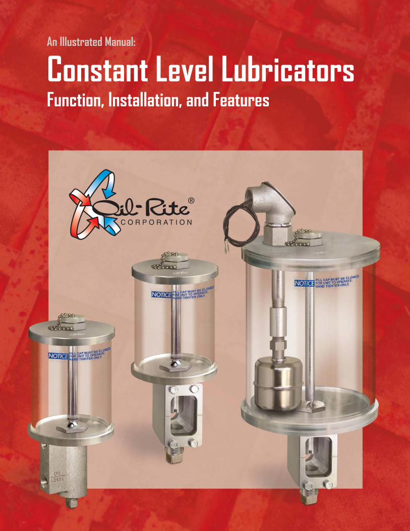
Constant Level LubricatorsFunction, Installation, and Features
An Illustrated Manual:
Manufactured in the U.S.A. by Oil-Rite Corporation.
www.oilrite.com 920-682-6173
Constant Level Lubricators
OverviewTypical Applications and Industries . . . . . . . . . . . . . . . . . . . . . . . . . . 3Fig. 1 - Installation Height . . . . . . . . . . . . . . . . . . . . . . . . . . . . . . . 3
OperationUpper Reservoir . . . . . . . . . . . . . . . . . . . . . . . . . . . . . . . . . . . . 4Lower Chamber . . . . . . . . . . . . . . . . . . . . . . . . . . . . . . . . . . . . 4Air Tight Seal . . . . . . . . . . . . . . . . . . . . . . . . . . . . . . . . . . . . . . 4Fig. 2 - Upper Reservoir Seal. . . . . . . . . . . . . . . . . . . . . . . . . . . . . . 4Liquid Seal . . . . . . . . . . . . . . . . . . . . . . . . . . . . . . . . . . . . . . . 4Liquid Seal Operation . . . . . . . . . . . . . . . . . . . . . . . . . . . . . . . . . 5Fig. 3 - Break in the Liquid Seal . . . . . . . . . . . . . . . . . . . . . . . . . . . . 5Fig. 4 - Restored Liquid Seal . . . . . . . . . . . . . . . . . . . . . . . . . . . . . . 5
InstallationLubricator Styles and Connections . . . . . . . . . . . . . . . . . . . . . . . . . . . 6Fig. 5 - Style CS and Style C Comparison . . . . . . . . . . . . . . . . . . . . . . . 6Mounting Options . . . . . . . . . . . . . . . . . . . . . . . . . . . . . . . . . . . 7Fig. 6 - Style CS (Viewing Window) Mounting Options . . . . . . . . . . . . . . . . . 7Fig. 7 - Style C Mounting Options . . . . . . . . . . . . . . . . . . . . . . . . . . . 7Piping. . . . . . . . . . . . . . . . . . . . . . . . . . . . . . . . . . . . . . . . . . 8Venting . . . . . . . . . . . . . . . . . . . . . . . . . . . . . . . . . . . . . . . . . 8Fig. 8 - Air Vent to Equipment Housing. . . . . . . . . . . . . . . . . . . . . . . . . 8Oil Slinging and Surge Levels . . . . . . . . . . . . . . . . . . . . . . . . . . . . . 9Height Adjustment (Models B2305 and B2311) . . . . . . . . . . . . . . . . . . . . 9Fig. 9 - Tool to Raise or Lower Spout Height (Models B2305 and B2311) . . . . . . . 9Fig. 10 - Adjusting the Spout Height (Models B2305 and B2311) . . . . . . . . . . 10Fig. 11 - Installation Where Oil is Pulled Upward. . . . . . . . . . . . . . . . . . . 11
Adding FluidSpring Activated Seal . . . . . . . . . . . . . . . . . . . . . . . . . . . . . . . . 12Fig. 12 - Oil Retention During Reservoir Refills . . . . . . . . . . . . . . . . . . . 12Initial Filling . . . . . . . . . . . . . . . . . . . . . . . . . . . . . . . . . . . . . 12
Features and OptionsStyle CS - Viewing Window, Pipe Mounting . . . . . . . . . . . . . . . . . . . . . 13Style CS - Viewing Window, Remote Mounting. . . . . . . . . . . . . . . . . . . . 14Style C - Without Viewing Window, Pipe Mounting. . . . . . . . . . . . . . . . . . 15Style C - Without Viewing Window, Remote Mounting . . . . . . . . . . . . . . . . 16Style CS - Viewing Window, With Adjustable Fluid Height . . . . . . . . . . . . . . 17Style CS - Viewing Window, With Low Level Switch . . . . . . . . . . . . . . . . . 18Style CS - Viewing Window, With Adjustable Fluid Height and Low Level Switch . . 19
TroubleshootingFluid Level in Viewing Window is Above Inscribed Line . . . . . . . . . . . . . . . 20Fig. 13 - Partially Open Cap Drains Reservoir . . . . . . . . . . . . . . . . . . . . 20Fluid Level Remains Constant Despite Depletion of Oil in Equipment Housing . . . 21Fig. 14 - Disrupted Fluid Level Between Lubricator and Equipment Housing . . . . 21Fluid Drains From the Upper Reservoir and Fills the Lower Chamber . . . . . . . . 22Fig. 15 - Bench Test . . . . . . . . . . . . . . . . . . . . . . . . . . . . . . . . . 22
Table of Contents
Manufactured in the U.S.A. by Oil-Rite Corporation.
www.oilrite.com 920-682-6173
An Illustrated Manual: Constant Level Lubricators . . . . . . . . . . . . . . . . . . . . Page 3
Equipment Housing(Example: Bearing Housing)
Constant Level Lubricator
InscribedLevel
OptimalLevel
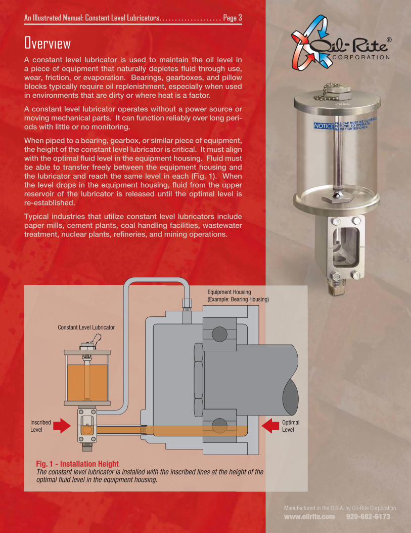
Fig. 1 - Installation HeightThe constant level lubricator is installed with the inscribed lines at the height of the optimal fluid level in the equipment housing.
OverviewA constant level lubricator is used to maintain the oil level in a piece of equipment that naturally depletes fluid through use, wear, friction, or evaporation. Bearings, gearboxes, and pillow blocks typically require oil replenishment, especially when used in environments that are dirty or where heat is a factor.
A constant level lubricator operates without a power source or moving mechanical parts. It can function reliably over long peri-ods with little or no monitoring.
When piped to a bearing, gearbox, or similar piece of equipment, the height of the constant level lubricator is critical. It must align with the optimal fluid level in the equipment housing. Fluid must be able to transfer freely between the equipment housing and the lubricator and reach the same level in each (Fig. 1). When the level drops in the equipment housing, fluid from the upper reservoir of the lubricator is released until the optimal level is re-established.
Typical industries that utilize constant level lubricators include paper mills, cement plants, coal handling facilities, wastewater treatment, nuclear plants, refineries, and mining operations.
An Illustrated Manual: Constant Level Lubricators . . . . . . . . . . . . . . . . . . . . Page 4
LowerChamber
UpperReservoir
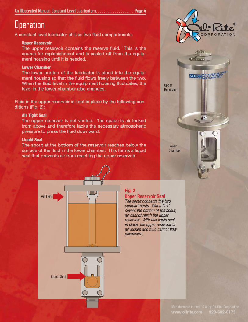
Air Tight
Fig. 2Upper Reservoir SealThe spout connects the two compartments. When fluid covers the bottom of the spout, air cannot reach the upper reservoir. With this liquid seal in place, the upper reservoir is air locked and fluid cannot flow downward.
Liquid Seal
Manufactured in the U.S.A. by Oil-Rite Corporation.
www.oilrite.com 920-682-6173
OperationA constant level lubricator utilizes two fluid compartments:
Upper ReservoirThe upper reservoir contains the reserve fluid. This is the source for replenishment and is sealed off from the equip-ment housing until it is needed.
Lower ChamberThe lower portion of the lubricator is piped into the equip-ment housing so that the fluid flows freely between the two. When the fluid level in the equipment housing fluctuates, the level in the lower chamber also changes.
Fluid in the upper reservoir is kept in place by the following con-ditions (Fig. 2):
Air Tight SealThe upper reservoir is not vented. The space is air locked from above and therefore lacks the necessary atmospheric pressure to press the fluid downward.
Liquid SealThe spout at the bottom of the reservoir reaches below the surface of the fluid in the lower chamber. This forms a liquid seal that prevents air from reaching the upper reservoir.
An Illustrated Manual: Constant Level Lubricators . . . . . . . . . . . . . . . . . . . . Page 5
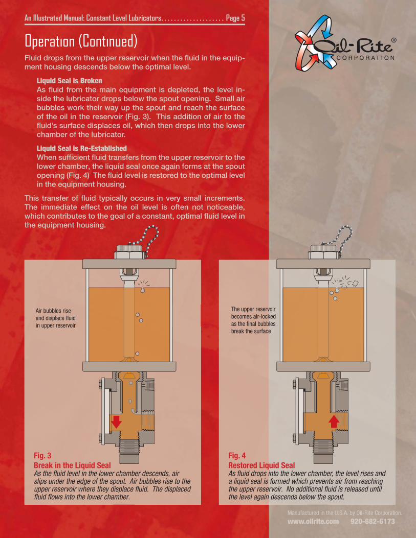
Fig. 3Break in the Liquid SealAs the fluid level in the lower chamber descends, air slips under the edge of the spout. Air bubbles rise to the upper reservoir where they displace fluid. The displaced fluid flows into the lower chamber.
Fig. 4Restored Liquid SealAs fluid drops into the lower chamber, the level rises and a liquid seal is formed which prevents air from reaching the upper reservoir. No additional fluid is released until the level again descends below the spout.
Air bubbles rise and displace fluid in upper reservoir
The upper reservoir becomes air-locked as the final bubbles break the surface
Operation (Continued)Fluid drops from the upper reservoir when the fluid in the equip-ment housing descends below the optimal level.
Liquid Seal is BrokenAs fluid from the main equipment is depleted, the level in-side the lubricator drops below the spout opening. Small air bubbles work their way up the spout and reach the surface of the oil in the reservoir (Fig. 3). This addition of air to the fluid’s surface displaces oil, which then drops into the lower chamber of the lubricator.
Liquid Seal is Re-EstablishedWhen sufficient fluid transfers from the upper reservoir to the lower chamber, the liquid seal once again forms at the spout opening (Fig. 4) The fluid level is restored to the optimal level in the equipment housing.
This transfer of fluid typically occurs in very small increments. The immediate effect on the oil level is often not noticeable, which contributes to the goal of a constant, optimal fluid level in the equipment housing.
Manufactured in the U.S.A. by Oil-Rite Corporation.
www.oilrite.com 920-682-6173
Manufactured in the U.S.A. by Oil-Rite Corporation.
www.oilrite.com 920-682-6173
An Illustrated Manual: Constant Level Lubricators . . . . . . . . . . . . . . . . . . . . Page 6
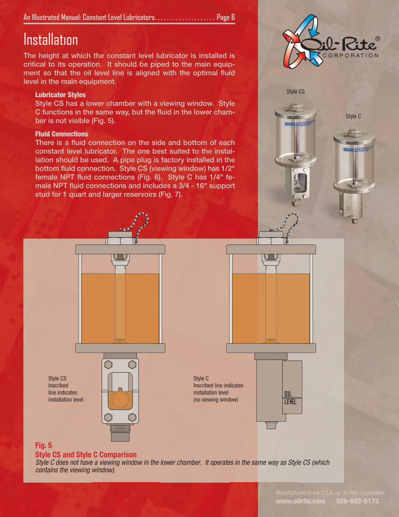
Fig. 5Style CS and Style C ComparisonStyle C does not have a viewing window in the lower chamber. It operates in the same way as Style CS (which contains the viewing window).
Style CSInscribed line indicates installation level
Style CInscribed line indicates installation level(no viewing window)
Style CS
Style C
InstallationThe height at which the constant level lubricator is installed is critical to its operation. It should be piped to the main equip-ment so that the oil level line is aligned with the optimal fluid level in the main equipment.
Lubricator StylesStyle CS has a lower chamber with a viewing window. Style C functions in the same way, but the fluid in the lower cham-ber is not visible (Fig. 5).
Fluid ConnectionsThere is a fluid connection on the side and bottom of each constant level lubricator. The one best suited to the instal-lation should be used. A pipe plug is factory installed in the bottom fluid connection. Style CS (viewing window) has 1/2" female NPT fluid connections (Fig. 6). Style C has 1/4" fe-male NPT fluid connections and includes a 3/4 - 16" support stud for 1 quart and larger reservoirs (Fig. 7).
An Illustrated Manual: Constant Level Lubricators . . . . . . . . . . . . . . . . . . . . Page 7
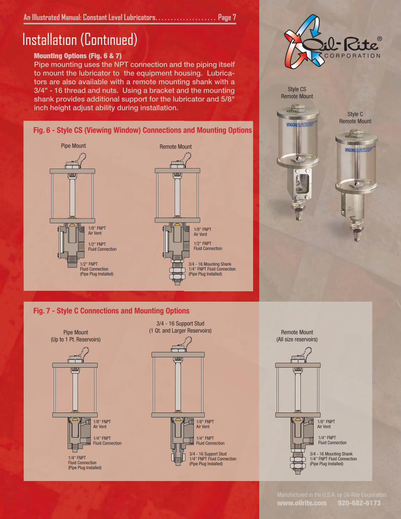
Fig. 6 - Style CS (Viewing Window) Connections and Mounting Options
1/2" FNPTFluid Connection
1/2" FNPTFluid Connection(Pipe Plug Installed)
1/8" FNPTAir Vent
3/4 - 16 Mounting Shank1/4" FNPT Fluid Connection(Pipe Plug Installed)
1/2" FNPTFluid Connection
1/8" FNPTAir Vent
Fig. 7 - Style C Connections and Mounting Options
Pipe Mount(Up to 1 Pt. Reservoirs)
Remote Mount(All size reservoirs)
3/4 - 16 Support Stud(1 Qt. and Larger Reservoirs)
1/4" FNPTFluid Connection
1/8" FNPTAir Vent
1/4" FNPTFluid Connection(Pipe Plug Installed)
3/4 - 16 Mounting Shank1/4" FNPT Fluid Connection(Pipe Plug Installed)
1/4" FNPTFluid Connection
1/8" FNPTAir Vent
1/4" FNPTFluid Connection
1/8" FNPTAir Vent
3/4 - 16 Support Stud1/4" FNPT Fluid Connection(Pipe Plug Installed)
Pipe Mount Remote Mount
Style CSRemote Mount
Style CRemote Mount
Installation (Continued)Mounting Options (Fig. 6 & 7)Pipe mounting uses the NPT connection and the piping itself to mount the lubricator to the equipment housing. Lubrica-tors are also available with a remote mounting shank with a 3/4" - 16 thread and nuts. Using a bracket and the mounting shank provides additional support for the lubricator and 5/8" inch height adjust ability during installation.
Manufactured in the U.S.A. by Oil-Rite Corporation.
www.oilrite.com 920-682-6173
Manufactured in the U.S.A. by Oil-Rite Corporation.
www.oilrite.com 920-682-6173Manufactured in the U.S.A. by Oil-Rite Corporation.
www.oilrite.com 920-682-6173
An Illustrated Manual: Constant Level Lubricators . . . . . . . . . . . . . . . . . . . . Page 8
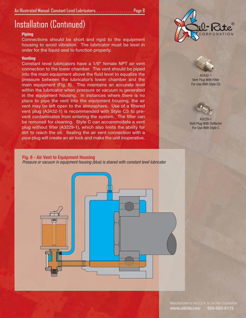
Fig. 8 - Air Vent to Equipment HousingPressure or vacuum in equipment housing (blue) is shared with constant level lubricator
A3432-1Vent Plug With Filter
For Use With Style CS
A3229-1Vent Plug With Deflector
For Use With Style C
Installation (Continued)PipingConnections should be short and rigid to the equipment housing to avoid vibration. The lubricator must be level in order for the liquid seal to function properly.
VentingConstant level lubricators have a 1/8" female NPT air vent connection to the lower chamber. The vent should be piped into the main equipment above the fluid level to equalize the pressure between the lubricator’s lower chamber and the main equipment (Fig. 8). This maintains an accurate level within the lubricator when pressure or vacuum is generated in the equipment housing. In instances where there is no place to pipe the vent into the equipment housing, the air vent may be left open to the atmosphere. Use of a filtered vent plug (A3432-1) is recommended with Style CS to pre-vent contaminates from entering the system. The filter can be removed for cleaning. Style C can accommodate a vent plug without filter (A3229-1), which also limits the ability for dirt to reach the oil. Sealing the air vent connection with a pipe plug will create an air lock and make the unit inoperative.
Manufactured in the U.S.A. by Oil-Rite Corporation.
www.oilrite.com 920-682-6173
An Illustrated Manual: Constant Level Lubricators . . . . . . . . . . . . . . . . . . . . Page 9
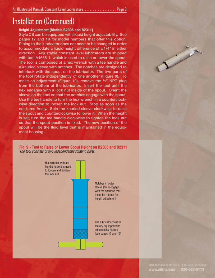
Fig. 9 - Tool to Raise or Lower Spout Height on B2305 and B2311The tool consists of two independently rotating parts.
Hex wrench with tee handle (green) is used to loosen and tighten the lock nut
Notches in outer sleeve (blue) engage with the spout so that it can be rotated for height adjustment
The lubricator must be factory equipped with adjustability feature (see pages 17 and 19)
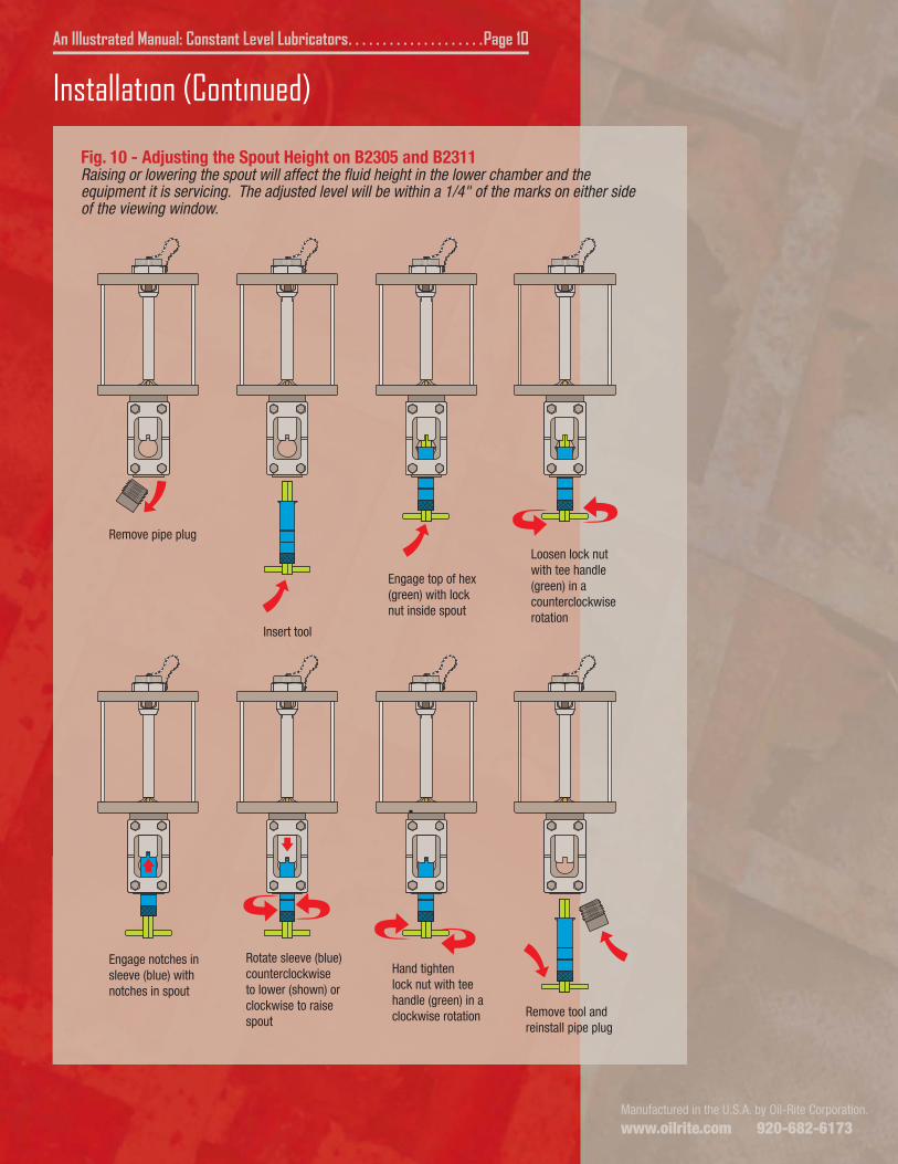
Installation (Continued)Height Adjustment (Models B2305 and B2311)Style CS can be equipped with liquid height adjustability. See pages 17 and 19 for model numbers that offer this option. Piping to the lubricator does not need to be changed in order to accommodate a liquid height difference of a 1/4" in either direction. Adjustable constant level lubricators are shipped with tool A4666-1, which is used to raise or lower the spout. The tool is composed of a hex wrench with a tee handle and a knurled sleeve with notches. The notches are designed to interlock with the spout on the lubricator. The two parts of the tool rotate independently of one another (Figure 9). To make an adjustment (Figure 10), remove the ½” NPT plug from the bottom of the lubricator. Insert the tool until the hex engages with a lock nut inside of the spout. Orient the sleeve on the tool so that the notches engage with the spout. Use the tee handle to turn the hex wrench in a counterclock-wise direction to loosen the lock nut. Stop as soon as the nut turns freely. Spin the knurled sleeve clockwise to raise the spout and counterclockwise to lower it. When the height is set, turn the tee handle clockwise to tighten the lock nut so that the spout position is fixed. The new position of the spout will be the fluid level that is maintained in the equip-ment housing.
Manufactured in the U.S.A. by Oil-Rite Corporation.
www.oilrite.com 920-682-6173
An Illustrated Manual: Constant Level Lubricators . . . . . . . . . . . . . . . . . . . .Page 10
Fig. 10 - Adjusting the Spout Height on B2305 and B2311Raising or lowering the spout will affect the fluid height in the lower chamber and the equipment it is servicing. The adjusted level will be within a 1/4" of the marks on either side of the viewing window.
Remove pipe plug
Insert tool
Engage top of hex (green) with lock nut inside spout
Loosen lock nut with tee handle (green) in a counterclockwise rotation
Engage notches in sleeve (blue) with notches in spout
Rotate sleeve (blue) counterclockwise to lower (shown) or clockwise to raise spout
Hand tighten lock nut with tee handle (green) in a clockwise rotation Remove tool and
reinstall pipe plug
Installation (Continued)
Manufactured in the U.S.A. by Oil-Rite Corporation.
www.oilrite.com 920-682-6173Manufactured in the U.S.A. by Oil-Rite Corporation.
www.oilrite.com 920-682-6173
An Illustrated Manual: Constant Level Lubricators . . . . . . . . . . . . . . . . . . . . Page 11
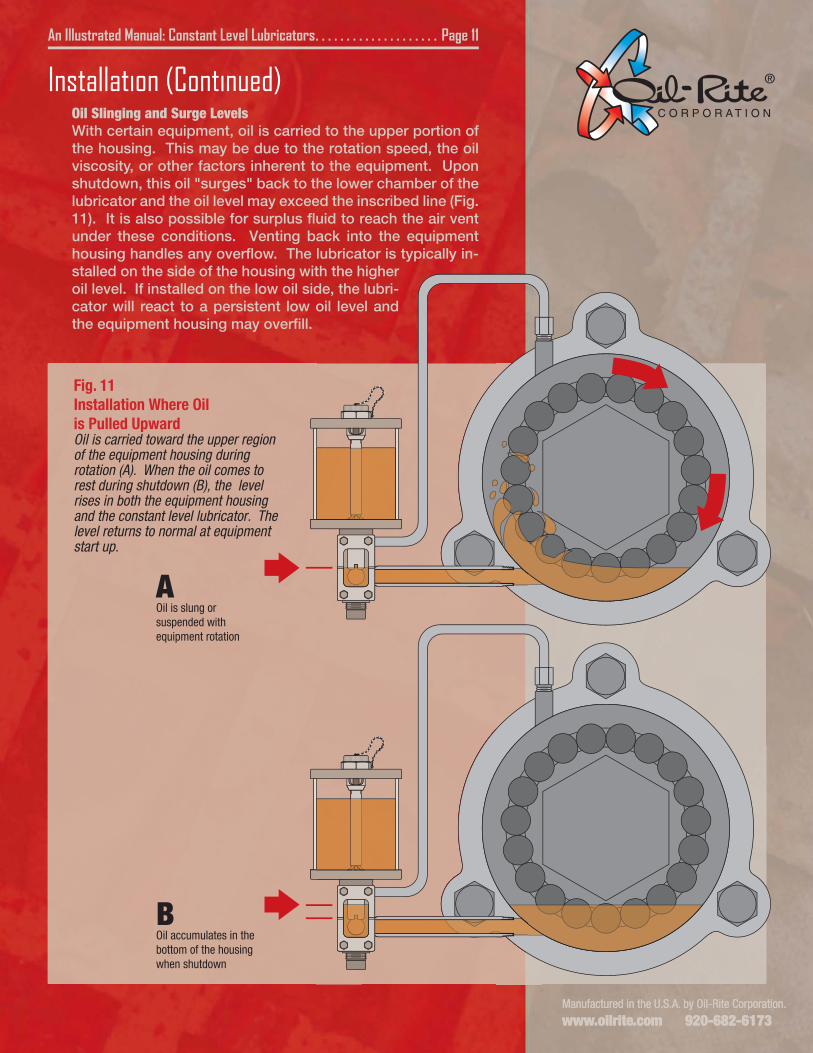
AOil is slung or suspended with equipment rotation
BOil accumulates in the bottom of the housing when shutdown
Fig. 11Installation Where Oilis Pulled UpwardOil is carried toward the upper region of the equipment housing during rotation (A). When the oil comes to rest during shutdown (B), the level rises in both the equipment housing and the constant level lubricator. The level returns to normal at equipment start up.
Installation (Continued)Oil Slinging and Surge LevelsWith certain equipment, oil is carried to the upper portion of the housing. This may be due to the rotation speed, the oil viscosity, or other factors inherent to the equipment. Upon shutdown, this oil "surges" back to the lower chamber of the lubricator and the oil level may exceed the inscribed line (Fig. 11). It is also possible for surplus fluid to reach the air vent under these conditions. Venting back into the equipment housing handles any overflow. The lubricator is typically in-stalled on the side of the housing with the higher oil level. If installed on the low oil side, the lubri-cator will react to a persistent low oil level and the equipment housing may overfill.
Manufactured in the U.S.A. by Oil-Rite Corporation.
www.oilrite.com 920-682-6173
An Illustrated Manual: Constant Level Lubricators . . . . . . . . . . . . . . . . . . . .Page 12
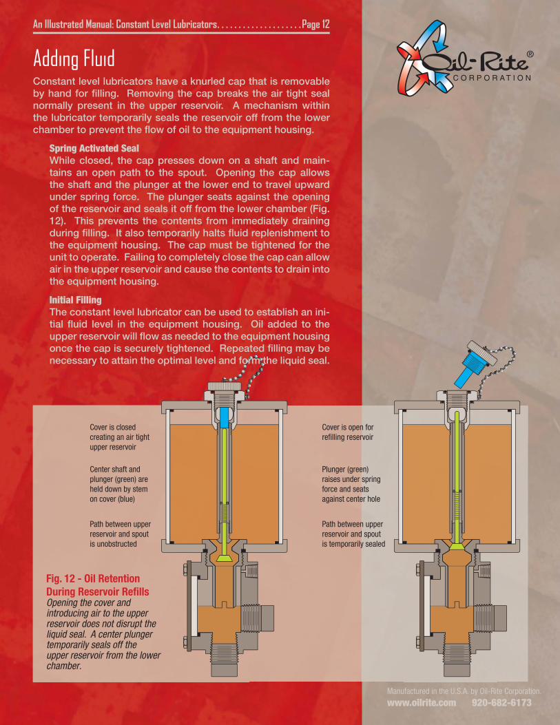
Fig. 12 - Oil Retention During Reservoir RefillsOpening the cover and introducing air to the upper reservoir does not disrupt the liquid seal. A center plunger temporarily seals off the upper reservoir from the lower chamber.
Cover is closed creating an air tight upper reservoir
Center shaft and plunger (green) are held down by stem on cover (blue)
Path between upper reservoir and spout is unobstructed
Cover is open for refilling reservoir
Plunger (green) raises under spring force and seats against center hole
Path between upper reservoir and spout is temporarily sealed
Adding FluidConstant level lubricators have a knurled cap that is removable by hand for filling. Removing the cap breaks the air tight seal normally present in the upper reservoir. A mechanism within the lubricator temporarily seals the reservoir off from the lower chamber to prevent the flow of oil to the equipment housing.
Spring Activated SealWhile closed, the cap presses down on a shaft and main-tains an open path to the spout. Opening the cap allows the shaft and the plunger at the lower end to travel upward under spring force. The plunger seats against the opening of the reservoir and seals it off from the lower chamber (Fig. 12). This prevents the contents from immediately draining during filling. It also temporarily halts fluid replenishment to the equipment housing. The cap must be tightened for the unit to operate. Failing to completely close the cap can allow air in the upper reservoir and cause the contents to drain into the equipment housing.
Initial FillingThe constant level lubricator can be used to establish an ini-tial fluid level in the equipment housing. Oil added to the upper reservoir will flow as needed to the equipment housing once the cap is securely tightened. Repeated filling may be necessary to attain the optimal level and form the liquid seal.
Manufactured in the U.S.A. by Oil-Rite Corporation.
www.oilrite.com 920-682-6173
An Illustrated Manual: Constant Level Lubricators . . . . . . . . . . . . . . . . . . . .Page 13
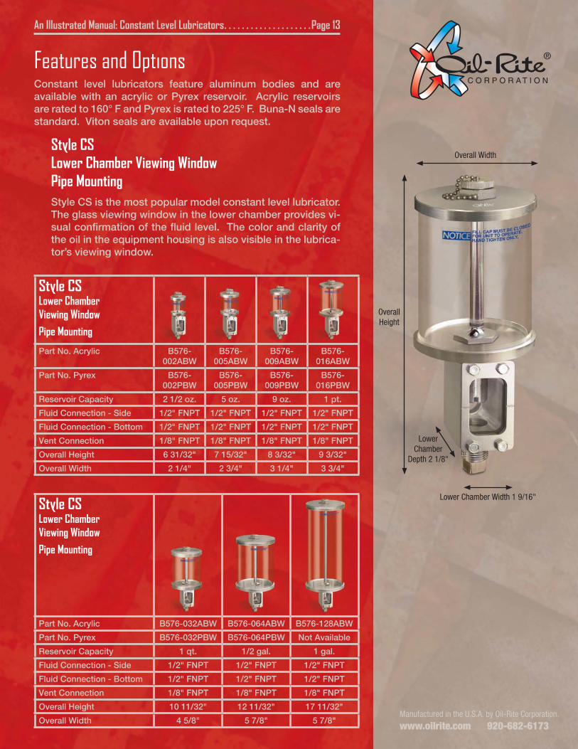
Features and OptionsConstant level lubricators feature aluminum bodies and are available with an acrylic or Pyrex reservoir. Acrylic reservoirs are rated to 160° F and Pyrex is rated to 225° F. Buna-N seals are standard. Viton seals are available upon request.
Style CSLower Chamber Viewing WindowPipe MountingStyle CS is the most popular model constant level lubricator. The glass viewing window in the lower chamber provides vi-sual confirmation of the fluid level. The color and clarity of the oil in the equipment housing is also visible in the lubrica-tor’s viewing window.
Style CSLower ChamberViewing Window
Pipe Mounting
Part No. Acrylic B576-002ABW
B576-005ABW
B576-009ABW
B576-016ABW
Part No. Pyrex B576-002PBW
B576-005PBW
B576-009PBW
B576-016PBW
Reservoir Capacity 2 1/2 oz. 5 oz. 9 oz. 1 pt.
Fluid Connection - Side 1/2" FNPT 1/2" FNPT 1/2" FNPT 1/2" FNPT
Fluid Connection - Bottom 1/2" FNPT 1/2" FNPT 1/2" FNPT 1/2" FNPT
Vent Connection 1/8" FNPT 1/8" FNPT 1/8" FNPT 1/8" FNPT
Overall Height 6 31/32" 7 15/32" 8 3/32" 9 3/32"
Overall Width 2 1/4" 2 3/4" 3 1/4" 3 3/4"
Style CSLower ChamberViewing Window
Pipe Mounting
Part No. Acrylic B576-032ABW B576-064ABW B576-128ABW
Part No. Pyrex B576-032PBW B576-064PBW Not Available
Reservoir Capacity 1 qt. 1/2 gal. 1 gal.
Fluid Connection - Side 1/2" FNPT 1/2" FNPT 1/2" FNPT
Fluid Connection - Bottom 1/2" FNPT 1/2" FNPT 1/2" FNPT
Vent Connection 1/8" FNPT 1/8" FNPT 1/8" FNPT
Overall Height 10 11/32" 12 11/32" 17 11/32"
Overall Width 4 5/8" 5 7/8" 5 7/8"
OverallHeight
Overall Width
Lower Chamber
Depth 2 1/8"
Lower Chamber Width 1 9/16"
Constant Level Lubricator . . . . . . . . . . . . . . . . . . . . . Page 7 of 12
Manufactured in the U.S.A. by Oil-Rite Corporation.
www.oilrite.com 920-682-6173Manufactured in the U.S.A. by Oil-Rite Corporation.
www.oilrite.com 920-682-6173
An Illustrated Manual: Constant Level Lubricators . . . . . . . . . . . . . . . . . . . .Page 14
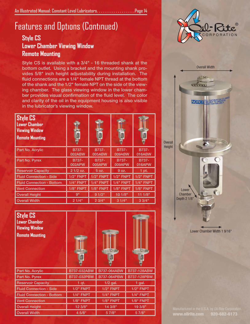
Features and Options (Continued)Style CSLower Chamber Viewing WindowRemote MountingStyle CS is available with a 3/4" - 16 threaded shank at the bottom outlet. Using a bracket and the mounting shank pro-vides 5/8" inch height adjustability during installation. The fluid connections are a 1/4" female NPT thread at the bottom of the shank and the 1/2" female NPT on the side of the view-ing chamber. The glass viewing window in the lower cham-ber provides visual confirmation of the fluid level. The color and clarity of the oil in the equipment housing is also visible in the lubricator’s viewing window.
Style CSLower ChamberViewing Window
Remote Mounting
Part No. Acrylic B737-002ABW
B737-005ABW
B737-009ABW
B737-016ABW
Part No. Pyrex B737-002APW
B737-005APW
B737-009APW
B737-016APW
Reservoir Capacity 2 1/2 oz. 5 oz. 9 oz. 1 pt.
Fluid Connection - Side 1/2" FNPT 1/2" FNPT 1/2" FNPT 1/2" FNPT
Fluid Connection - Bottom 1/4" FNPT 1/4" FNPT 1/4" FNPT 1/4" FNPT
Vent Connection 1/8" FNPT 1/8" FNPT 1/8" FNPT 1/8" FNPT
Overall Height 9" 9 1/2" 10 1/8" 11 1/8"
Overall Width 2 1/4" 2 3/4" 3 1/4" 3 3/4"
Style CSLower ChamberViewing Window
Remote Mounting
Part No. Acrylic B737-032ABW B737-064ABW B737-128ABW
Part No. Pyrex B737-032PBW B737-064PBW B737-128PBW
Reservoir Capacity 1 qt. 1/2 gal. 1 gal.
Fluid Connection - Side 1/2" FNPT 1/2" FNPT 1/2" FNPT
Fluid Connection - Bottom 1/4" FNPT 1/4" FNPT 1/4" FNPT
Vent Connection 1/8" FNPT 1/8" FNPT 1/8" FNPT
Overall Height 12 3/8" 14 3/8" 19 3/8"
Overall Width 4 5/8" 5 7/8" 5 7/8"
Lower Chamber Width 1 9/16"
OverallHeight
Overall Width
Lower Chamber
Depth 2 1/8"
Manufactured in the U.S.A. by Oil-Rite Corporation.
www.oilrite.com 920-682-6173
An Illustrated Manual: Constant Level Lubricators . . . . . . . . . . . . . . . . . . . .Page 15
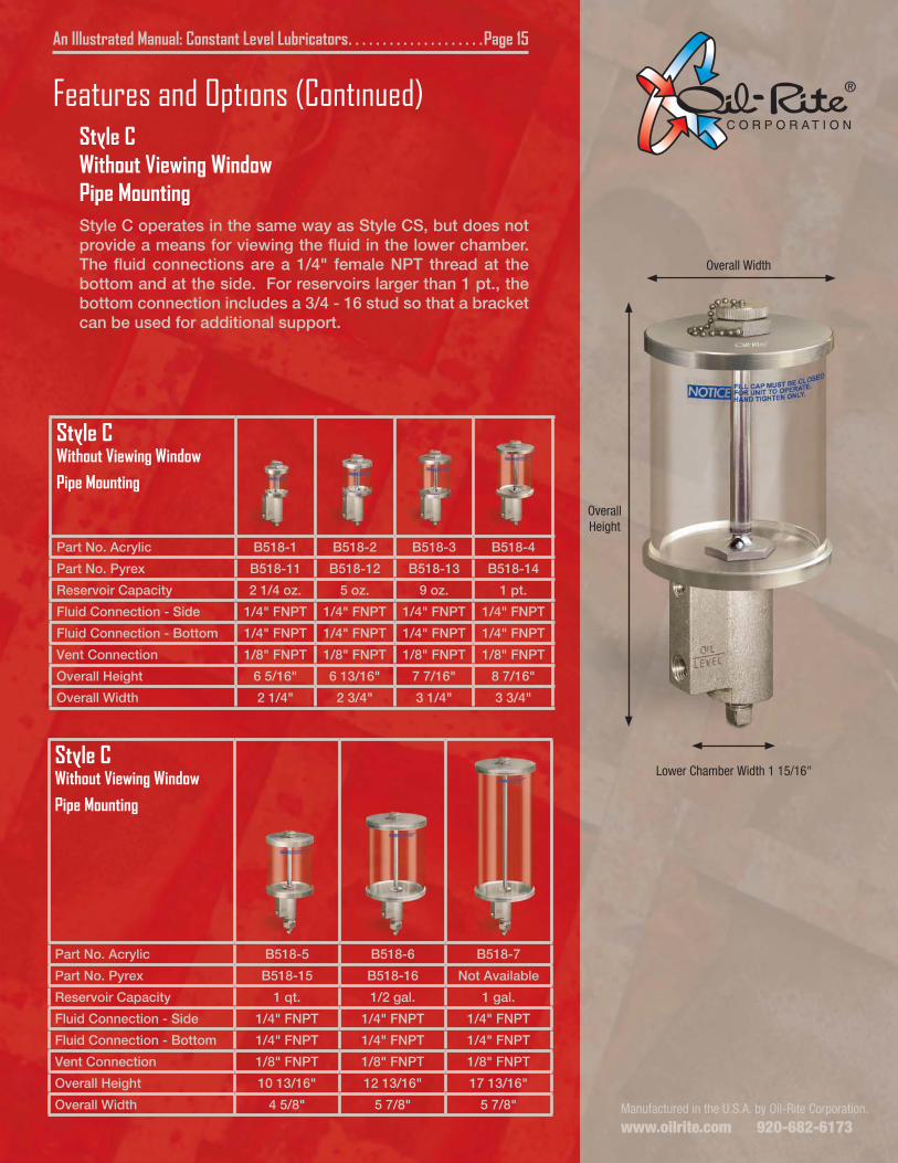
Features and Options (Continued)Style CWithout Viewing WindowPipe MountingStyle C operates in the same way as Style CS, but does not provide a means for viewing the fluid in the lower chamber. The fluid connections are a 1/4" female NPT thread at the bottom and at the side. For reservoirs larger than 1 pt., the bottom connection includes a 3/4 - 16 stud so that a bracket can be used for additional support.
Style CWithout Viewing Window
Pipe Mounting
Part No. Acrylic B518-1 B518-2 B518-3 B518-4
Part No. Pyrex B518-11 B518-12 B518-13 B518-14
Reservoir Capacity 2 1/4 oz. 5 oz. 9 oz. 1 pt.
Fluid Connection - Side 1/4" FNPT 1/4" FNPT 1/4" FNPT 1/4" FNPT
Fluid Connection - Bottom 1/4" FNPT 1/4" FNPT 1/4" FNPT 1/4" FNPT
Vent Connection 1/8" FNPT 1/8" FNPT 1/8" FNPT 1/8" FNPT
Overall Height 6 5/16" 6 13/16" 7 7/16" 8 7/16"
Overall Width 2 1/4" 2 3/4" 3 1/4" 3 3/4"
Style CWithout Viewing Window
Pipe Mounting
Part No. Acrylic B518-5 B518-6 B518-7
Part No. Pyrex B518-15 B518-16 Not Available
Reservoir Capacity 1 qt. 1/2 gal. 1 gal.
Fluid Connection - Side 1/4" FNPT 1/4" FNPT 1/4" FNPT
Fluid Connection - Bottom 1/4" FNPT 1/4" FNPT 1/4" FNPT
Vent Connection 1/8" FNPT 1/8" FNPT 1/8" FNPT
Overall Height 10 13/16" 12 13/16" 17 13/16"
Overall Width 4 5/8" 5 7/8" 5 7/8"
Lower Chamber Width 1 15/16"
OverallHeight
Overall Width
Manufactured in the U.S.A. by Oil-Rite Corporation.
www.oilrite.com 920-682-6173
An Illustrated Manual: Constant Level Lubricators . . . . . . . . . . . . . . . . . . . .Page 16
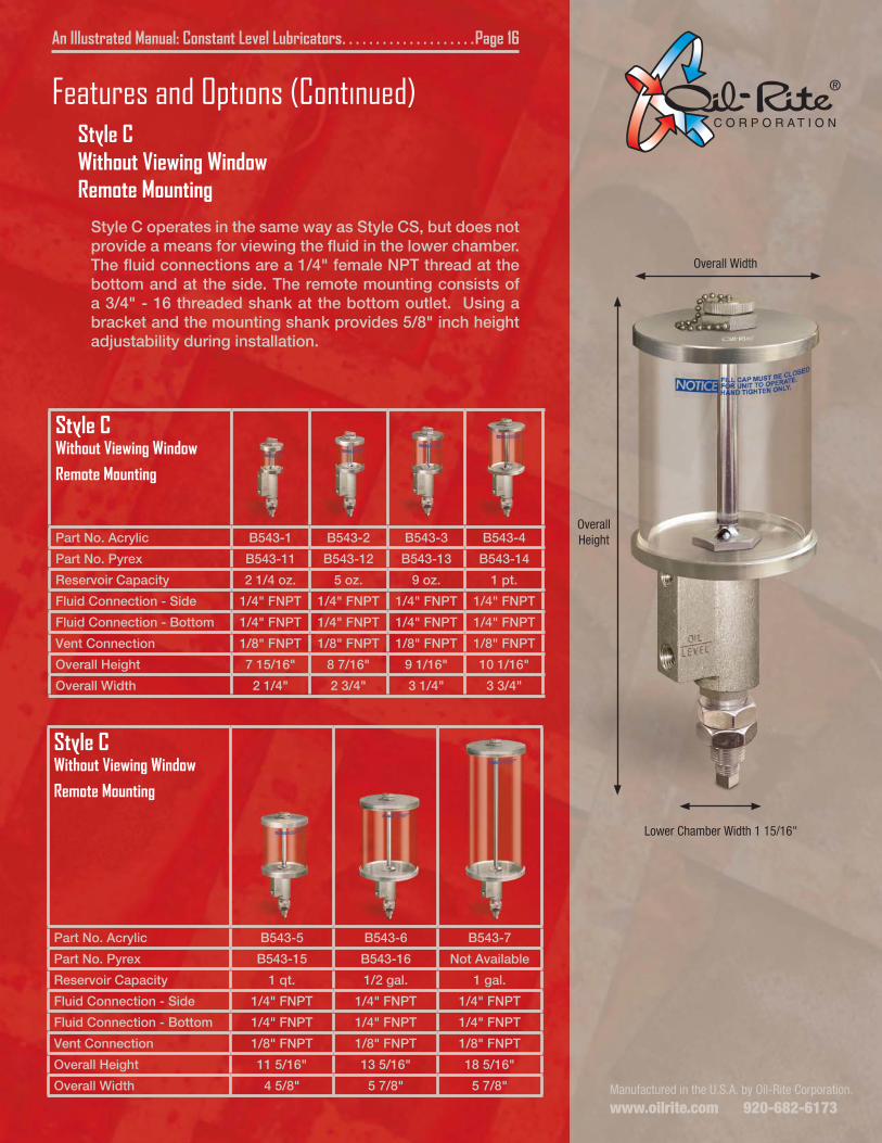
Features and Options (Continued)Style CWithout Viewing WindowRemote Mounting
Style C operates in the same way as Style CS, but does not provide a means for viewing the fluid in the lower chamber. The fluid connections are a 1/4" female NPT thread at the bottom and at the side. The remote mounting consists of a 3/4" - 16 threaded shank at the bottom outlet. Using a bracket and the mounting shank provides 5/8" inch height adjustability during installation.
Style CWithout Viewing Window
Remote Mounting
Part No. Acrylic B543-1 B543-2 B543-3 B543-4
Part No. Pyrex B543-11 B543-12 B543-13 B543-14
Reservoir Capacity 2 1/4 oz. 5 oz. 9 oz. 1 pt.
Fluid Connection - Side 1/4" FNPT 1/4" FNPT 1/4" FNPT 1/4" FNPT
Fluid Connection - Bottom 1/4" FNPT 1/4" FNPT 1/4" FNPT 1/4" FNPT
Vent Connection 1/8" FNPT 1/8" FNPT 1/8" FNPT 1/8" FNPT
Overall Height 7 15/16" 8 7/16" 9 1/16" 10 1/16"
Overall Width 2 1/4" 2 3/4" 3 1/4" 3 3/4"
Style CWithout Viewing Window
Remote Mounting
Part No. Acrylic B543-5 B543-6 B543-7
Part No. Pyrex B543-15 B543-16 Not Available
Reservoir Capacity 1 qt. 1/2 gal. 1 gal.
Fluid Connection - Side 1/4" FNPT 1/4" FNPT 1/4" FNPT
Fluid Connection - Bottom 1/4" FNPT 1/4" FNPT 1/4" FNPT
Vent Connection 1/8" FNPT 1/8" FNPT 1/8" FNPT
Overall Height 11 5/16" 13 5/16" 18 5/16"
Overall Width 4 5/8" 5 7/8" 5 7/8"
Lower Chamber Width 1 15/16"
OverallHeight
Overall Width
Manufactured in the U.S.A. by Oil-Rite Corporation.
www.oilrite.com 920-682-6173
Style CSLower ChamberViewing Window
With Adjustable Fluid Height
Part No. Acrylic B2305-002ABW
B2305-005ABW
B2305-009ABW
B2305-016ABW
Part No. Pyrex B2305-002PBW
B2305-005PBW
B2305-009PBW
B2305-016PBW
Reservoir Capacity 2 1/2 oz. 5 oz. 9 oz. 1 pt.
Fluid Connection - Side 1/2" FNPT 1/2" FNPT 1/2" FNPT 1/2" FNPT
Fluid Connection - Bottom 1/2" FNPT 1/2" FNPT 1/2" FNPT 1/2" FNPT
Vent Connection 1/8" FNPT 1/8" FNPT 1/8" FNPT 1/8" FNPT
Overall Height 6 31/32" 7 15/32" 8 3/32" 9 3/32"
Overall Width 2 1/4" 2 3/4" 3 1/4" 3 3/4"
Style CSLower ChamberViewing Window
With Adjustable Fluid Height
Part No. Acrylic B2305-032ABW
B2305-064ABW
B2305-128ABW
Part No. Pyrex B2305-032PBW
B2305-064PBW
Not Available
Reservoir Capacity 1 qt. 1/2 gal. 1 gal.
Fluid Connection - Side 1/2" FNPT 1/2" FNPT 1/2" FNPT
Fluid Connection - Bottom 1/2" FNPT 1/2" FNPT 1/2" FNPT
Vent Connection 1/8" FNPT 1/8" FNPT 1/8" FNPT
Overall Height 10 11/32" 12 11/32" 17 11/32"
Overall Width 4 5/8" 5 7/8" 5 7/8"
An Illustrated Manual: Constant Level Lubricators . . . . . . . . . . . . . . . . . . . . Page 17
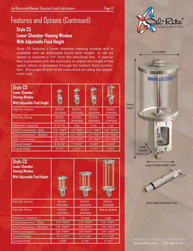
Features and Options (Continued)Style CSLower Chamber Viewing WindowWith Adjustable Fluid HeightStyle CS features a lower chamber viewing window and is available with an adjustable liquid level height. It can be raised or lowered a 1/4" from the inscribed line. A special tool is provided with the lubricator to adjust the height of the spout, which is accessed through the bottom fluid connec-tion. See pages 9 and 10 for instuctions on using the adjust-ment tool.
Lower Chamber Width 2 3/8"
OverallHeight
Overall Width
Spout Height Adjustment Tool
Lower Chamber
Depth 2 1/8"
Manufactured in the U.S.A. by Oil-Rite Corporation.
www.oilrite.com 920-682-6173
An Illustrated Manual: Constant Level Lubricators . . . . . . . . . . . . . . . . . . . .Page 18
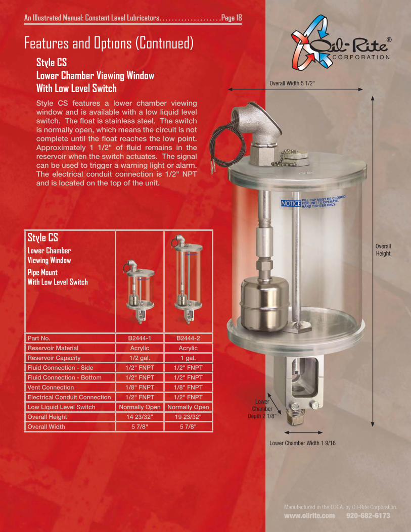
Features and Options (Continued)Style CSLower Chamber Viewing WindowWith Low Level SwitchStyle CS features a lower chamber viewing window and is available with a low liquid level switch. The float is stainless steel. The switch is normally open, which means the circuit is not complete until the float reaches the low point. Approximately 1 1/2" of fluid remains in the reservoir when the switch actuates. The signal can be used to trigger a warning light or alarm. The electrical conduit connection is 1/2" NPT and is located on the top of the unit.
Lower Chamber Width 1 9/16
OverallHeight
Overall Width 5 1/2"
Style CSLower ChamberViewing Window
Pipe MountWith Low Level Switch
Part No. B2444-1 B2444-2
Reservoir Material Acrylic Acrylic
Reservoir Capacity 1/2 gal. 1 gal.
Fluid Connection - Side 1/2" FNPT 1/2" FNPT
Fluid Connection - Bottom 1/2" FNPT 1/2" FNPT
Vent Connection 1/8" FNPT 1/8" FNPT
Electrical Conduit Connection 1/2" FNPT 1/2" FNPT
Low Liquid Level Switch Normally Open Normally Open
Overall Height 14 23/32" 19 23/32"
Overall Width 5 7/8" 5 7/8"
Lower Chamber
Depth 2 1/8"
Manufactured in the U.S.A. by Oil-Rite Corporation.
www.oilrite.com 920-682-6173
An Illustrated Manual: Constant Level Lubricators . . . . . . . . . . . . . . . . . . . .Page 19
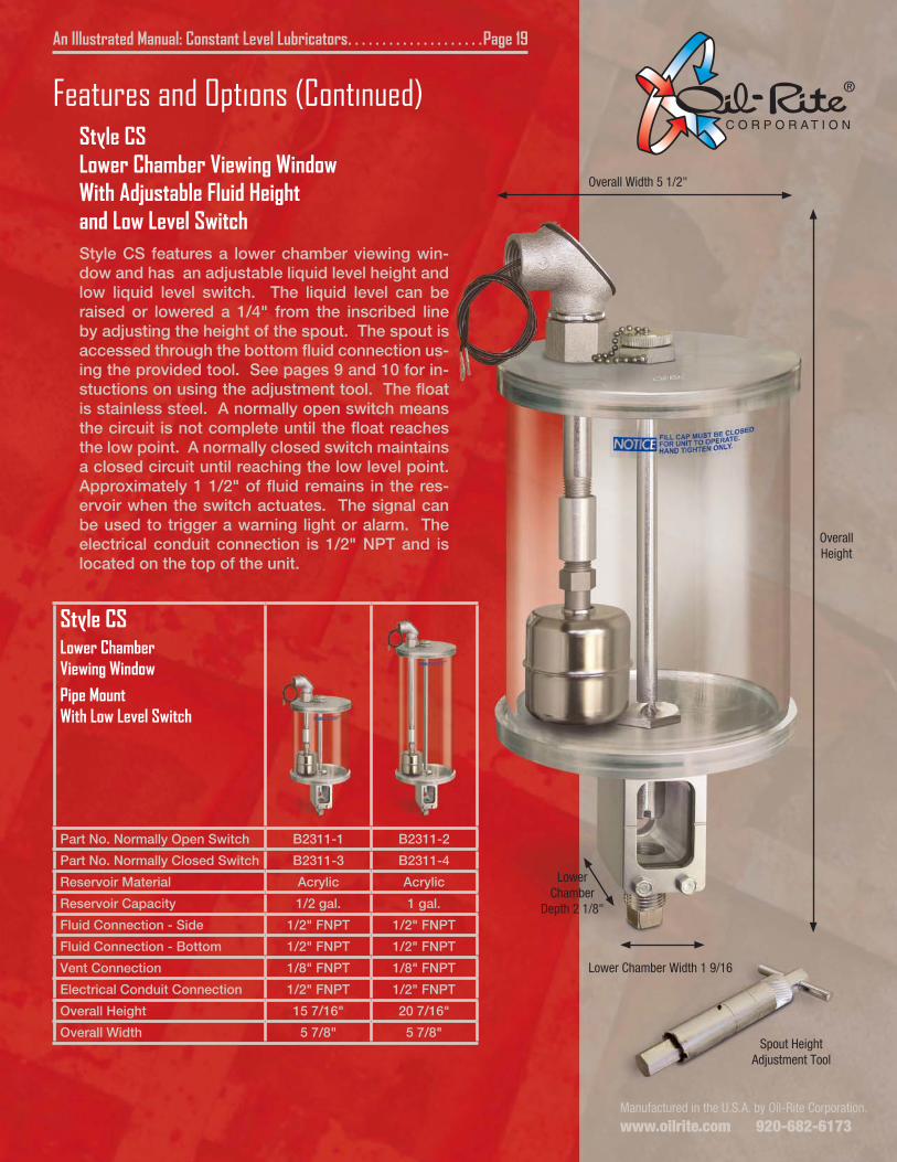
Features and Options (Continued)Style CSLower Chamber Viewing WindowWith Adjustable Fluid Heightand Low Level SwitchStyle CS features a lower chamber viewing win-dow and has an adjustable liquid level height and low liquid level switch. The liquid level can be raised or lowered a 1/4" from the inscribed line by adjusting the height of the spout. The spout is accessed through the bottom fluid connection us-ing the provided tool. See pages 9 and 10 for in-stuctions on using the adjustment tool. The float is stainless steel. A normally open switch means the circuit is not complete until the float reaches the low point. A normally closed switch maintains a closed circuit until reaching the low level point. Approximately 1 1/2" of fluid remains in the res-ervoir when the switch actuates. The signal can be used to trigger a warning light or alarm. The electrical conduit connection is 1/2" NPT and is located on the top of the unit.
Style CSLower ChamberViewing Window
Pipe MountWith Low Level Switch
Part No. Normally Open Switch B2311-1 B2311-2
Part No. Normally Closed Switch B2311-3 B2311-4
Reservoir Material Acrylic Acrylic
Reservoir Capacity 1/2 gal. 1 gal.
Fluid Connection - Side 1/2" FNPT 1/2" FNPT
Fluid Connection - Bottom 1/2" FNPT 1/2" FNPT
Vent Connection 1/8" FNPT 1/8" FNPT
Electrical Conduit Connection 1/2" FNPT 1/2" FNPT
Overall Height 15 7/16" 20 7/16"
Overall Width 5 7/8" 5 7/8"
OverallHeight
Overall Width 5 1/2"
Spout HeightAdjustment Tool
Lower Chamber Width 1 9/16
Lower Chamber
Depth 2 1/8"
Manufactured in the U.S.A. by Oil-Rite Corporation.
www.oilrite.com 920-682-6173
An Illustrated Manual: Constant Level Lubricators . . . . . . . . . . . . . . . . . . . Page 20
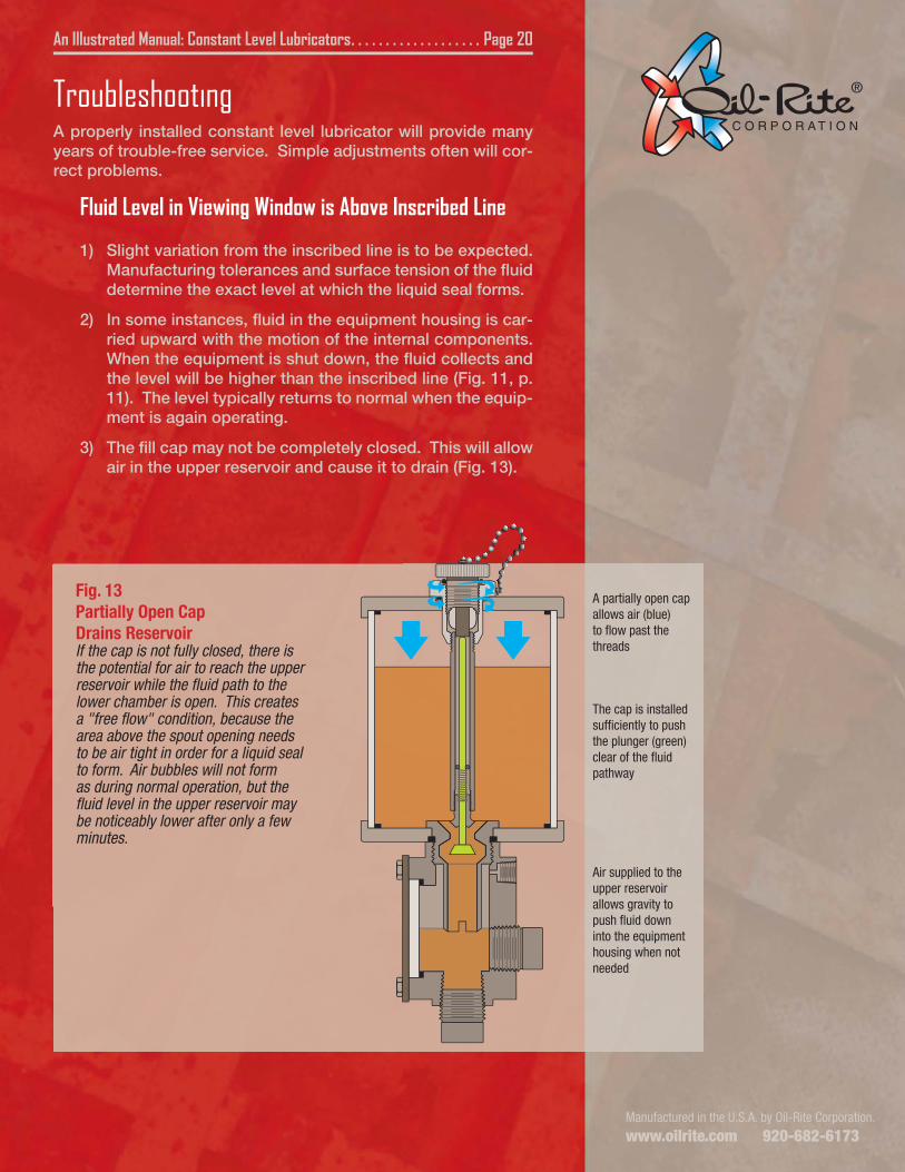
Fig. 13Partially Open CapDrains ReservoirIf the cap is not fully closed, there is the potential for air to reach the upper reservoir while the fluid path to the lower chamber is open. This creates a "free flow" condition, because the area above the spout opening needs to be air tight in order for a liquid seal to form. Air bubbles will not form as during normal operation, but the fluid level in the upper reservoir may be noticeably lower after only a few minutes.
A partially open cap allows air (blue) to flow past the threads
Air supplied to the upper reservoir allows gravity to push fluid down into the equipment housing when not needed
The cap is installed sufficiently to push the plunger (green) clear of the fluid pathway
TroubleshootingA properly installed constant level lubricator will provide many years of trouble-free service. Simple adjustments often will cor-rect problems.
Fluid Level in Viewing Window is Above Inscribed Line
1) Slight variation from the inscribed line is to be expected. Manufacturing tolerances and surface tension of the fluid determine the exact level at which the liquid seal forms.
2) In some instances, fluid in the equipment housing is car-ried upward with the motion of the internal components. When the equipment is shut down, the fluid collects and the level will be higher than the inscribed line (Fig. 11, p. 11). The level typically returns to normal when the equip-ment is again operating.
3) The fill cap may not be completely closed. This will allow air in the upper reservoir and cause it to drain (Fig. 13).
Manufactured in the U.S.A. by Oil-Rite Corporation.
www.oilrite.com 920-682-6173
An Illustrated Manual: Constant Level Lubricators . . . . . . . . . . . . . . . . . . . .Page 21
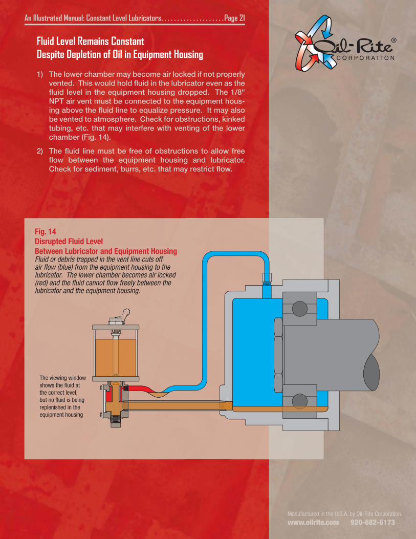
Fig. 14Disrupted Fluid LevelBetween Lubricator and Equipment HousingFluid or debris trapped in the vent line cuts off air flow (blue) from the equipment housing to the lubricator. The lower chamber becomes air locked (red) and the fluid cannot flow freely between the lubricator and the equipment housing.
The viewing window shows the fluid at the correct level, but no fluid is being replenished in the equipment housing
The cap is installed sufficiently to push the plunger (green) clear of the fluid pathway
Fluid Level Remains ConstantDespite Depletion of Oil in Equipment Housing
1) The lower chamber may become air locked if not properly vented. This would hold fluid in the lubricator even as the fluid level in the equipment housing dropped. The 1/8" NPT air vent must be connected to the equipment hous-ing above the fluid line to equalize pressure. It may also be vented to atmosphere. Check for obstructions, kinked tubing, etc. that may interfere with venting of the lower chamber (Fig. 14).
2) The fluid line must be free of obstructions to allow free flow between the equipment housing and lubricator. Check for sediment, burrs, etc. that may restrict flow.
Manufactured in the U.S.A. by Oil-Rite Corporation.
www.oilrite.com 920-682-6173
An Illustrated Manual: Constant Level Lubricators . . . . . . . . . . . . . . . . . . . Page 22
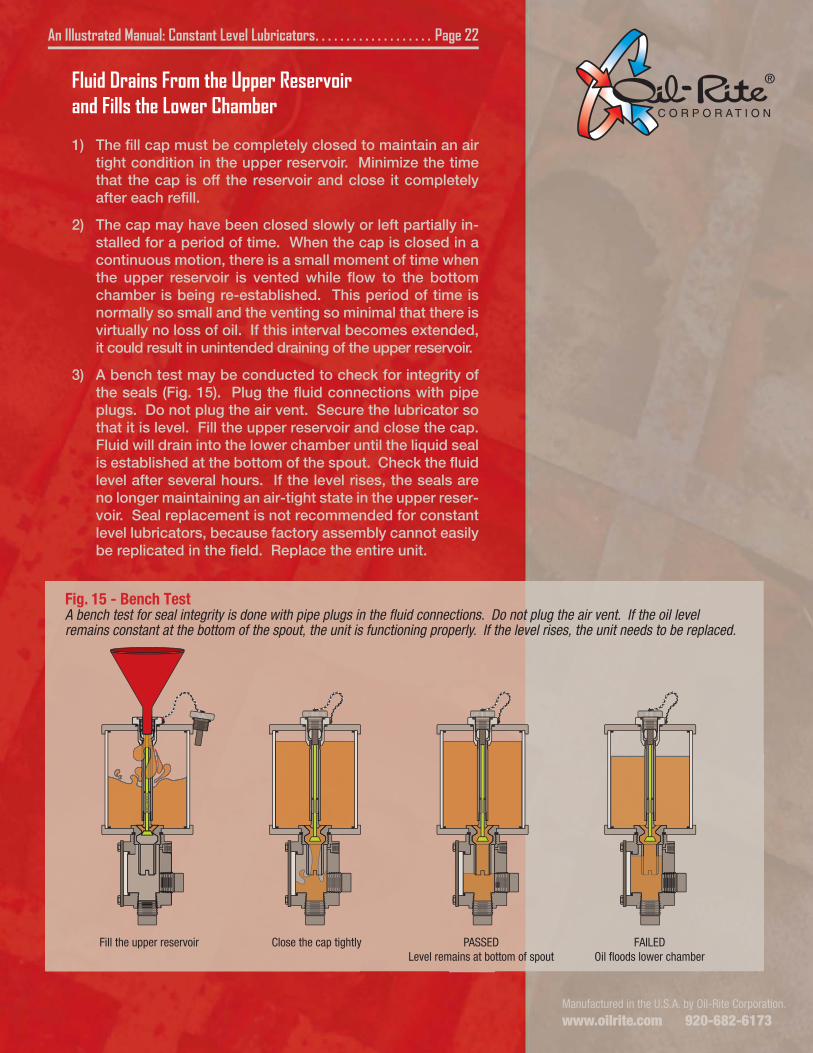
Fig. 15 - Bench TestA bench test for seal integrity is done with pipe plugs in the fluid connections. Do not plug the air vent. If the oil level remains constant at the bottom of the spout, the unit is functioning properly. If the level rises, the unit needs to be replaced.
Fill the upper reservoir Close the cap tightly PASSEDLevel remains at bottom of spout
FAILEDOil floods lower chamber
Fluid Drains From the Upper Reservoirand Fills the Lower Chamber
1) The fill cap must be completely closed to maintain an air tight condition in the upper reservoir. Minimize the time that the cap is off the reservoir and close it completely after each refill.
2) The cap may have been closed slowly or left partially in-stalled for a period of time. When the cap is closed in a continuous motion, there is a small moment of time when the upper reservoir is vented while flow to the bottom chamber is being re-established. This period of time is normally so small and the venting so minimal that there is virtually no loss of oil. If this interval becomes extended, it could result in unintended draining of the upper reservoir.
3) A bench test may be conducted to check for integrity of the seals (Fig. 15). Plug the fluid connections with pipe plugs. Do not plug the air vent. Secure the lubricator so that it is level. Fill the upper reservoir and close the cap. Fluid will drain into the lower chamber until the liquid seal is established at the bottom of the spout. Check the fluid level after several hours. If the level rises, the seals are no longer maintaining an air-tight state in the upper reser-voir. Seal replacement is not recommended for constant level lubricators, because factory assembly cannot easily be replicated in the field. Replace the entire unit.