Embed Size (px)
Citation preview
1
AN EVEN-PHASE MULTI-MOTOR VECTOR CONTROLLED DRIVE WITH SINGLE INVERTER SUPPLY AND SERIES CONNECTION OF STATOR WINDINGS
E. Levi, M. Jones, S.N. Vukosavic
Liverpool John Moores University School of Engineering Liverpool L3 3AF, UK
ABSTRACT: Vector control principles enable independent flux and torque control of an ac machine by means of
only two stator d-q axis current components. This means that in ac machines with a phase number greater than three
there exist additional degrees of freedom, which are nowadays used to enhance the overall torque production of a
multi-phase machine through injection of higher stator current harmonics. However, these additional degrees of
freedom can be used to control independently other machines within a multi-motor drive system. In order to do so,
it is necessary to connect in series stator windings of all the multi-phase machines, with an appropriate phase
transposition. A vector control algorithm is then applied to each machine separately, total inverter phase current
references are created by summation of individual machine phase current references and supply to the stator
windings of the multi-machine set is provided from a single current controlled voltage source inverter (VSI). The
concept is introduced in this paper using the general theory of electrical machines and all the possible situations that
may arise for an even number of phases are examined. Although an induction motor drive is considered throughout,
the concept is equally applicable to all ac machines with sinusoidal stator and rotor flux distribution. Its main
advantage is the potential for saving in the number of inverter legs, compared to an equivalent three-phase motor
drive system. The saving depends on the number of phases and, for an even phase number, comes into existence
when the number of phases is equal to or greater than eight. Various even phase numbers are considered in detail
and appropriate connection diagrams are given. Verification of the proposed multi-phase multi-motor drive is
provided by simulation of a ten-phase four-motor system.
1. INTRODUCTION
Industrial electrical drive applications often require a number of variable speed drives. Examples include
textile and paper manufacturing, robotics, traction, electric vehicles, etc. In vast majority of cases these multi-motor
drive systems require independent control of individual motors. Standard solution in such situations is to use a set
of three-phase motors, which are supplied from their own PWM VSI and all the inverters are connected to the
common dc link. Either vector control or direct torque control can be used for independent control of the motors
within a group in order to obtain a high performance [1]. If a multi-motor system consists of k three-phase
machines, this approach requires 3k inverter legs. Numerous solutions have therefore been proposed for reducing
the total number of inverter legs required in a multi-machine system [2-4]. The two solutions analysed in detail in
[4] require only 2k and 2k+1 inverter legs, respectively. However, both configurations lead to a substantial increase
in the total harmonic distortion and to a reduced voltage capability. The authors conclude that the configuration
with 2k+1 legs offers a better performance than the configuration with 2k legs. Both are however inferior with
respect to the standard solution with 3k legs.

2
In certain applications, such as for example traction, it is possible to use a multi-motor system that consists
of k three-phase motors connected in parallel and supplied from a single PWM VSI [5-7]. Vector control is used in
this case and it is a prerequisite that all the motors develop an identical electromagnetic torque [7]. Due to parallel
connection and supply from a single inverter, the whole multi-machine system always has to operate with the same
supply voltage and frequency, so that the means for independent control of individual motors within the multi-
machine system do not exist. Very much the same applies to another parallel connection of k three-phase motors,
supplied this time from a single PWM current source inverter [8]. Since V/f control is used in [8], the motors are
always subjected to the same supply voltage and frequency conditions.
Supply of variable speed electric drives from inverters enables substitution of the standard three-phase
configuration with an appropriate multi-phase (n-phase) configuration. Ever since the inception of the first multi-
phase (five-phase) inverter-fed induction motor drive in 1969 [9], the interest in multi-phase drive systems has been
steadily increasing, as evidenced by recent survey papers [10,11]. Major advantages of using a multi-phase machine
instead of a three-phase machine are detailed in [12] and can be summarised as follows: higher torque density,
greater efficiency, reduced torque pulsation, greater fault tolerance, reduction in the required rating per inverter leg
and therefore simpler, more reliable power conditioning equipment. Additionally, noise characteristics of the drive
improve as well [13]. Higher torque density in a multi-phase machine is possible since, apart from the fundamental
spatial field harmonic, space harmonic fields can be used to contribute to the total torque production [12,14-17].
This advantage stems from the fact that vector control of the machine’s flux and torque, produced by the interaction
of the fundamental field component and the fundamental stator current component, requires only two stator currents
(d-q current components). In a multi-phase machine, with at least five phases or more, there are therefore additional
degrees of freedom, which can be utilised to enhance the torque production through injection of higher order stator
current harmonics. The concept is equally applicable to any ac machine type and has been successfully
demonstrated for induction [15,17] and synchronous reluctance [14,16] machines. In a five-phase machine the third
harmonic current injection can be used [14,15,17], while in a nine-phase machine it is possible to use injection of
the third, the fifth and the seventh current harmonic [16]. This is so since injection of any specific current harmonic
requires again two current components, similar to the torque/flux production due to fundamental harmonic. In
general, the possibility for an increase in the torque density increases as the number of phases increases. However,
it appears that once when the number of phases reaches fifteen, further increase does not provide any further
important advantage [12].
As already noted, vector control of a multi-phase machine requires only two currents if only the
fundamental of the field is utilised. Although the remaining degrees of freedom can be used to enhance the overall
motor torque production, they can also be used in an entirely different manner, as the basis for a multi-motor multi-
phase drive system development. This papers attempts to develop this idea in a systematic manner. An n–phase ac
machine is considered, such that the number of phases is an even number. It is shown that, by connecting the multi-
phase stator windings of the k machines in series, with an appropriate phase transposition, it becomes possible to
realise a completely independent vector control of the machines although only one inverter is used. There are not
any restrictions on the type of the ac machine used within the drive system, machines’ power rating, loading and
operating speed. The initial idea behind this concept was for the first time indicated in [18], where the notion of an
n-dimensional space for an n-phase machine [19] was applied in the analysis and only a two-motor, five-phase
system was studied. The concept has never been examined for an even number of phases and is developed here

3
using the general theory of electric machines [20]. The necessary phase transposition in the series winding
connection is established by analysing the properties of the decoupling transformation matrix. So-called
connectivity matrix is introduced and connection diagrams are given for some characteristic phase numbers.
Classification of all the even phase numbers is further provided, with regard to the maximum number of
connectable machines and the number of phases of individual machines in the group. The concept is verified by
simulation of a ten-phase four-motor drive system in torque mode of operation. Its main advantages and
shortcomings are assessed in the concluding section of the paper. A corresponding study for an arbitrary odd
number of phases has also been done and the results will be reported in near future.
2. MODELLING OF AN n-PHASE AC MACHINE 2.1 General remarks
An n-phase machine, such that the spatial displacement between any two consecutive stator phases equals
α = 2π/n, is under consideration. Although the type of the ac machine is irrelevant, it is assumed that the machine is
an induction motor. Both stator and rotor windings are treated as n–phase, for the sake of generality. It is assumed
that the spatial distribution of the stator and rotor flux is sinusoidal, since the intention is to control torque
production due to fundamental harmonic only. All the inductances within the stator and the rotor n-phase winding
are therefore constants and the mutual inductances between the stator and rotor phases contain only the fundamental
harmonic. Rotor winding is taken as referred to the stator winding. All the other standard assumptions of the
general theory of electrical machines apply. The phase number can be odd or even. Considerations are in this paper
restricted to an even number of phases.
It is important to note that only the true n-phase machines are discussed here. This means that the m-th
phase and the (n/2 + m)-th phase are positioned 180 degrees apart and are supplied with currents in phase
opposition. Each such an n-phase winding can be reconfigured into so-called semi n-phase winding [10], with an
effective number of phases equal to n/2 (the customary three-phase machine is in essence a semi six-phase machine,
[10]). While this reconfiguration halves the number of phases and would therefore halve the number of inverter
legs, it would simultaneously halve the number of connectable machines as well. Furthermore, if the original even
phase number n is such that n/2 is a prime number, semi n-phase winding becomes a winding with an odd number
of phases (these phase numbers are, as already noted, beyond the scope of this paper). If the original phase number
n is a power of two, reconfiguration into a semi n-phase winding requires a neutral conductor for operation with the
balanced system of currents [10] (a semi four-phase machine is customarily known as a two-phase machine; since
the currents are 90 degrees apart, the two-phase system requires three wires). It is for these reasons that the analysis
in the paper is restricted to true n-phase systems (n = even), with spatial displacement between any two consecutive
windings equal to α = 2π/n.
2.2 Decoupling transformation The machine model in phase variable form is transformed using decoupling (Clark’s) transformation
matrix [20]. Decoupling transformation substitutes the original set of n phase currents with a new set of n
transformed currents. Decoupling transformation matrix for an arbitrary even phase number can be given in power
invariant form with [20]:

4
⎥⎥⎥⎥⎥⎥⎥⎥⎥⎥⎥⎥⎥⎥⎥⎥⎥⎥
⎦
⎤
⎢⎢⎢⎢⎢⎢⎢⎢⎢⎢⎢⎢⎢⎢⎢⎢⎢⎢
⎣
⎡
−−−−
⎟⎠⎞
⎜⎝⎛ −
−⎟⎠⎞
⎜⎝⎛ −
−⎟⎠⎞
⎜⎝⎛ −
−⎟⎠⎞
⎜⎝⎛ −
⎟⎠⎞
⎜⎝⎛ −
⎟⎠⎞
⎜⎝⎛ −
⎟⎠⎞
⎜⎝⎛ −
⎟⎠⎞
⎜⎝⎛ −
⎟⎠⎞
⎜⎝⎛ −
⎟⎠⎞
⎜⎝⎛ −
⎟⎠⎞
⎜⎝⎛ −
⎟⎠⎞
⎜⎝⎛ −
−−−
−−−
−−−
=
−
+
−
−
212121.....21212121212121.....212121212
2sin2
22sin2
23sin.....2
23sin2
22sin2
2sin0
22cos
222cos
223cos.....
223cos
222cos
22cos1
........................................3sin6sin9sin.....9sin6sin3sin0
3cos6cos9cos.....9cos6cos3cos12sin4sin6sin.....6sin4sin2sin0
2cos4cos6cos.....6cos4cos2cos1sin2sin3sin.....3sin2sinsin0
cos2cos3cos.....3cos2coscos1
00
...2
24
24
2
2
1
1
αααααα
αααααα
αααααααααααααααααααααααααααααααααααα
βα
nnnnnn
nnnnnn
y
x
yxyx
n
n
n
C
(1)
The first two rows in (1) define stator current components that will lead to fundamental flux and torque production
(α-β components; stator to rotor coupling appears only in the equations for α-β components), while the last two
rows define the two zero sequence components. In between, there are (n−4)/2 pairs of rows which define (n−4)/2
pairs of stator current components, termed further on x-y components. As will be shown shortly, x-y pairs of
current components will play an important role in realising independent control of the machines connected in series.
Equations for pairs of x-y components are completely decoupled from all the other components and stator
to rotor coupling does not appear either [20]. These components do not contribute to torque production when
sinusoidal distribution of the flux around the air-gap is assumed. Zero sequence components will not exist in any
star-connected multi-phase system without neutral conductor. This means that at most (n−2)/2 machines (for an
even phase number) can be connected in series. In order to do so it is necessary to ensure that the flux/torque
producing currents of one machine do not produce flux and torque in all the other machines of the group. A simple
series connection of stator windings is obviously not going to achieve this goal. An appropriate phase transposition
is therefore required when connecting the windings in series, as discussed shortly.
2.3 Rotational transformation
Since stator to rotor coupling appears only in the equations for α-β components regardless of the machine
type and torque production due to the fundamental field component is therefore entirely governed by α-β
components, rotational transformation is applied to α-β equations only [20]. Assuming transformation into an
arbitrary common reference frame ( ∫= dtas ωθ ), the transformation matrices for stator and rotor variables are
1.....
1cossinsincos
1.....
1cossinsincos
⎥⎥⎥⎥⎥⎥
⎦
⎤
⎢⎢⎢⎢⎢⎢
⎣
⎡−
=
⎥⎥⎥⎥⎥⎥
⎦
⎤
⎢⎢⎢⎢⎢⎢
⎣
⎡−
=ββββ
θθθθ
r
ss
ss
s DD (2)
where β = θs−θ and θ is the instantaneous rotor angular position.
Upon application of the decoupling transformation (1) and rotational transformation (2), an n–phase
induction machine is described with the following voltage equilibrium and flux linkage equations (p ≡ d/dt):

5
rororrosososso
rororrosososso
ryryrrysysyssy
rxrxrrxsxsxssx
ryryrrysysyssy
rxrxrrxsxsxssx
qrdraqrrqrqsdsaqssqs
drqradrrdrdsqsadssds
piRvpiRvpiRvpiRv
piRv pψiRvpψiRvpiRv
piRv pψiRvpψiRvpiRv
piRvpiRv
piRvpiRv
−−−−−−
++++++
+=+=+=+=
+==+=+==+=
+==+=+==+=
+−+==++=
+−−==+−=
ψψψψ
ψψ
ψψ
ψψωωψψω
ψψωωψψω
.........................................................................................................
0 0
0 0
)(0
)(0
222222
222222
111111
111111
(3)
rolrrosolsso
rolrrosolsso
rylrrysylssy
rxlrrxsxlssx
rylrrysylssy
rxlrrxsxlssx
qsmqrmlrqrqrmqsmlsqs
dsmdrmlrdrdrmdsmlsds
iLiLiLiL
iLiLiLiL
iLiLiLiL
iLiLLiLiLLiLiLLiLiLL
−−−−
++++
====
====
====
++=++=++=++=
ψψψψ
ψψψψ
ψψψψ
ψψψψ
.....................................................................................
)( )()( )(
2222
2222
1111
1111
(4)
where ( )MnLm 2= and M is the maximum value of the stator to rotor mutual inductances in the phase variable
model. Torque equation is given with
[ ]qrdsqsdrme iiiiPLT −= (5)
3. SERIES CONNECTION OF MULTI-PHASE STATOR WINDINGS
Since only one pair of stator α-β (d-q) current components is required for the flux and torque control in
one machine, there is a possibility of using the remaining degrees of freedom ([(n–2)/2–1] pairs of stator x-y current
components) for control of other machines that are to be connected in series with the first machine. However, if the
control of the machines with series connected stator windings is to be decoupled one from the other, it is necessary
that the flux/torque producing currents of one machine do not produce flux and torque in all the other machines in
the group. In other words, the connection of stator windings of k=(n-2)/2 multi-phase machines must be such that
what one machine sees as the d-q axis stator current components the other machines see as x-y current components,
and vice versa. It then becomes possible to completely independently control speed (position, torque) of (n-2)/2
machines while supplying the drive system from a single current-controlled voltage source inverter. Achievement
of the stated goal requires an appropriate phase transposition when connecting the stator windings in series. Phase
transposition means shift in connection of the phases 1,2, ... n of the first machine to the phases 1,2, ... n of the
second machine, etc., where 1,2,3…n is the flux/torque producing phase sequence of the given machine according
to the spatial distribution of the phases within the stator winding. The required phase transposition follows directly
from the decoupling transformation matrix (1).
According to (1), phase ‘1’ of all the machines will be connected directly in series (the first column in (1)).
The phase transposition for phase ‘1’ is therefore 0 degrees and the phase step is zero. However, phase ‘2’ of the
first machine will be connected to phase ‘3’ of the second machine, which will be further connected to phase ‘4’ of

6
the third machine and so on. The phase transposition moving from one machine to the other is the spatial angle α
and the phase step is 1. This follows from the second column of the transformation matrix. In a similar manner
phase ‘3’ of the first machine (the third element in the first row of (1) with spatial displacement of 2α) is connected
to the phase ‘5’ of the second machine, which further gets connected to phase ‘7’ of the third machine, and so on.
The phase transposition is 2α, and the phase step is 2. This follows from the third column of (1). Further, phase ‘4’
the first machine needs to be connected to the phase ‘7’ of the second machine which gets connected to the phase
‘10’ of the third machine and so on. Here the phase step is 3 and the phases are transposed by 3α. This corresponds
to the fourth column in (1). For phase ‘5’ of the first machine the phase transposition equals 4α and phase step is 4,
for phase ‘6’ the phase step is 5 and phase transposition equals 5α, and so on. If a number obtained in this way is
greater than the number of phases n, resetting is performed by deducting j x n (j = 1,2,3...) from the number so that
the resulting number belongs to the set [1,n]. It should be noted that for an n-phase supply system (n = even) not all
of the k-connectable machines will be n-phase. This means that for some machines in the group the resulting set of
the utilised phase numbers in the connection diagram, obtained in the described way, will be a sub-set of the set
[1,n]. The statement is clarified in what follows, by examining certain phase numbers in more detail.
This explanation enables construction of a connection table, which is further called connectivity matrix.
Connectivity matrix and the corresponding connection diagram are given next for some selected even phase
numbers. Flux/torque producing phase sequence for any particular machine is denoted in the connectivity matrices
with numbers 1,2,3…n while the notation a,b,c,d,…. is used in corresponding connection diagrams.
The minimum even number of phases that will enable series connection is n = 6. The corresponding
connectivity matrix, obtained on the basis of the given procedure, is given in Table I. As can be seen from the last
row of this matrix, only phases 1,3 and 5 of the second machine are utilised. As spatial displacement between these
phases is 120°, it follows that the second machine is a three-phase machine rather than a six-phase machine. The
corresponding connection diagram is given in Fig. 1. Note that the flux/torque producing currents of the six-phase
machine mutually cancel at the connection points with the three-phase machine. This means that the three-phase
machine will not suffer from any adverse effects due to the series connection with the six-phase machine. This of
course does not hold true for the six-phase machine.
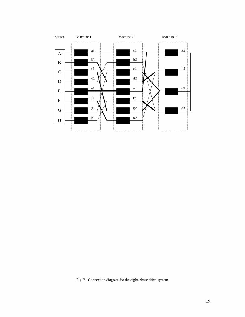
In the case of an eight-phase system it is possible to connect three machines in series. The connectivity
matrix is the one given in Table II. The first and the third machine are eight-phase, however the second machine is
four-phase since only phases 1,3,5,7 are utilised (and spatial displacement is therefore 90 degrees). It is important to
note that, when connecting the machines in series to the source, all the machines with the highest phase number
must come first. This means that the actual sequence of connection of the three machines to the source has to be
M1, M3, M2, as shown in the connection diagram in Fig. 2. This is so since flux/torque producing currents of the
machine with a higher phase number cancel when entering the machine with the lower phase number (for example,
in the six-phase case of Fig. 1. phase currents a1 and d1 of the six-phase machine are in phase opposition, so that
their sum at the point of entry into the phase a2 of the second machine is zero).
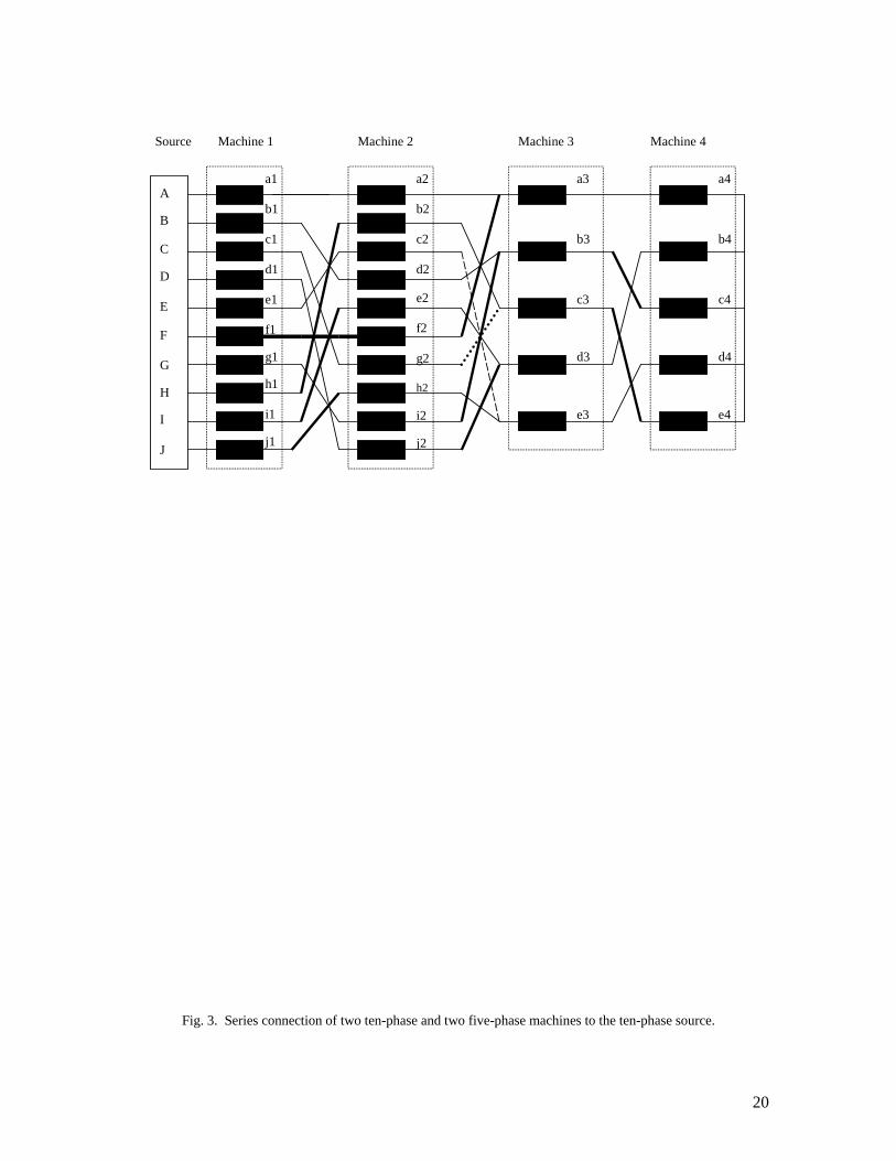
Ten-phase case is illustrated in Table III and Fig. 3. It is now possible to connect four machines in series.
Two of them are ten-phase (M1 and M3), while the remaining two (M2 and M4) are five-phase. Such a situation
will exist always when the even phase number n is such that n/2 is a prime number, as discussed in the next section.
Once more, the two machines with the higher phase number have to be connected at first in series with the source.
Five-phase machines are then added at the end of the chain, as shown in Fig. 3.
7
In the three cases illustrated so far it was possible to connect the maximum possible number k = (n–2)/2 of
machines. Indeed, for any even phase number one expects, on the basis of the considerations given so far, that the
number of connectable machines will be k = (n–2)/2. This is however not always the case. Consider for example a
twelve-phase system. Connectivity matrix is shown in Table IV. Machines M1 and M5 are twelve-phase, machine
M2 is six-phase, machine M3 is four-phase, and machine M4 is three-phase. Hence, it is not possible to connect all
five machines in series since the ratio 4/3 is not an integer (an attempt to connect a four-phase machine to a three-
phase machine leads to short-circuiting of all the terminals). At most four machines can be connected in series, two
twelve-phase, followed by the six-phase and three-phase. The ordering is M1, M5, M2, M4.
Table V summarises the situation which arises for all the even phase numbers up to eighteen. Bold boxes
apply to the phase numbers such that n/2 is a prime number. As can be seen from the table, only k/2 machines are n-
phase, while the remaining k/2 machines are n/2–phase. In the eighteen-phase case the number of connectable
machines is smaller than eight (at most seven), since the ratio 9/6 is not an integer. Similar situation arises in the
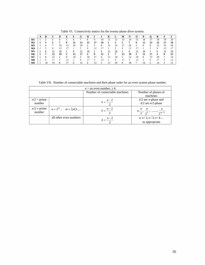
twenty-phase case (Table VI), where both four-phase and five-phase machines appear. There are five twenty-phase
machines (M1,M3,M7,M9), two ten-phase machines (M2,M6), two five-phase machines (M4,M8) and one four-
phase machine (M5). At most eight machines can be connected using the sequence M1,M3,M7,M9,M2,M6,M4,M8
(four twenty-phase, two ten-phase, and two five-phase). But, eight machines can be connected in series with the
odd number of phases n = 17, which requires three inverter legs less.
4. NUMBER OF CONNECTABLE MACHINES
There are three different situations that may arise, depending on the properties of the phase number n. At
least one case for each of them has been illustrated in the previous section.
a) Let the number n/2 be a prime number. The number of machines that can be connected in series equals
2)2( −= nk (6)
The number of phases of individual k machines will be as follows: k/2 machines will be n-phase and k/2 machines
will be n/2-phase. The ordering of machines has to follow the rule that higher number of phases comes first. Hence
the first k/2 machines are n-phase, while the subsequent k/2 machines are n/2-phase. This means that one half of the
machines are with an even number of phase, while the rest are with an odd number of phases. The phase numbers
belonging to this category are n = 6, 10, 14, 22, 26, 34, 38, 46, 58, 62, 74 etc. The six-phase and the ten-phase case
were elaborated in the previous section.
b) Consider next the number of phases n such that n/2 is not a prime number, but it satisfies the condition
.....5,4,3 , 2 == mn m (7)
The number of machines that can be connected remains to be given with (6). Once again not all k machines are of
the phase number equal to n. In the example illustrated previously n = 8, k = 3. However, only two machines are
eight-phase, while the third one is four-phase. Hence for the general case of m ≥ 3 the phase numbers of the
machines that can be connected in series will be: 22 2 ......., ,2 ,2 , −mnnnn (8)
This case arises when the phase number of the multi-drive system takes values of n = 8, 16, 32, 64, etc.
c) The third possible case arises for all the other even n. The number of machines that can be connected is

8
2)2( −< nk (9)
Series connection of machines whose phase number ratio is not an integer is not possible. This case was illustrated
for n = 12 and 20 in the previous section. Again, among these k machines only a certain number is with n phases.
The other machines have phase numbers equal to ...4/,3/,2/ nnn as appropriate. There are at least three different
phase numbers among the multi-machine set. Phase numbers that belong to this group are 12, 18, 20, 24, 28, etc.
Cases b) and c) can be regarded as sub-cases of a more general case for which n/2 is not a prime number.
The total number of connectable machines is however not the same, ((6) and (9), respectively). A summary of all
possible situations for an even number of phases is provided in Table VII. Of practical value are only phase
numbers that enable series connection of the maximum number of connectable machines (i.e. cases a) and b)).
5. VECTOR CONTROL OF THE MULTI-MOTOR SYSTEM
A standard method of achieving indirect rotor flux oriented control of a current-fed ac machine is
considered here. It is assumed that there is a rotor position sensor attached to each machine of the group. The basic
form of the vector controller is the same as for a three-phase machine of the same type and the only difference is in
the co-ordinate transformation, where n phase current references are generated by means of the co-ordinate
transformation described with (1) and (2), instead of three. The indirect vector controller for operation in the base
speed (constant flux) region is illustrated in Fig. 4 for an n-phase induction machine. The form of the vector
controller is the same for a permanent magnet synchronous and synchronous reluctance motor, provided that the
constant K1 is set to zero and that an appropriate value is assigned to the stator d-axis current reference.
Current control is performed in the stationary reference frame, using inverter phase currents. It is important
to notice that the presented form of the vector-controlled multi-phase multi-motor drive system is valid when the
current control is exercised in the stationary reference frame. This is so since minimisation of the inverter phase
current errors through inverter switching automatically generates appropriate voltages required for compensation of
the additional voltage drops in the machines, caused by the flow of x-y current components. The concept can be
extended to current control in the rotating reference frame. This is however beyond the scope of this paper.
Either ramp-comparison or hysteresis current control can be used. Generation of individual machine phase
current references is done first, using Fig. 4 (superscript Mj stands for the machine under consideration, M1 to Mk):
( ) ( )
( ) ( )])1(sin)1(cos[2
------------------------------------------
]sincos[2
]sincos[2
)()(*)()(*)(*
)()(*)()(*)(*2
)()(*)()(*)(*1
αφαφ
αφαφ
φφ
−−−−−=
−−−=
−=
ninin
i
iin
i
iin
i
Mjr
Mjqs
Mjr
Mjds
Mjn
Mjr
Mjqs
Mjr
Mjds
Mj
Mjr
Mjqs
Mjr
Mjds
Mj
(10)
Inverter reference currents are further built, respecting the appropriate connection diagram for the given
number of inverter phases. Inverter reference current creation has to take into account the existence of machines
with different phase numbers within the group. Taking as an example the six-phase inverter with a six-phase and a
three-phase machine, illustrated in Fig. 1 and Table I, the inverter current references are determined with:

9
*2
*1
**2
*1
*
*2
*1
**2
*1
*
*2
*1
**2
*1
*
5.0 5.0
5.0 5.0
5.0 5.0
cfFbeE
adDccC
bbBaaA
iiiiii
iiiiii
iiiiii
+=+=
+=+=
+=+=
(11)
Similarly, for the ten-phase system, illustrated in Fig. 3 and Table III, the inverter phase current references
are governed with the following expressions:
*4
*3
*2
*1
**4
*3
*2
*1
*
*4
*3
*2
*1
**4
*3
*2
*1
*
*4
*3
*2
*1
**4
*3
*2
*1
*
*4
*3
*2
*1
**4
*3
*2
*1
*
*4
*3
*2
*1
**4
*3
*2
*1
*
5.05.0 5.05.0
5.05.0 5.05.0
5.05.0 5.05.0
5.05.0 5.05.0
5.05.0 5.05.0
dehjJdeceE
bdeiIbdjdD
ecbhHecgcC
cbigGcbdbB
aaffFaaaaA
iiiiiiiiii
iiiiiiiiii
iiiiiiiiii
iiiiiiiiii
iiiiiiiiii
+++=+++=
+++=+++=
+++=+++=
+++=+++=
+++=+++=
(12)
Inverter phase current references will be built in this manner for any phase number n. It is only necessary to form an
appropriate connectivity matrix and the corresponding connection diagram in order to arrive at an equation of the
form given in (11) and (12). Since current control is performed in the stationary reference frame using total inverter
phase currents, inverter output phase voltages will be of the form required to minimize the phase current errors.
Inverter output phase voltages are again governed with the appropriate connection diagram for the given number of
phases. For the already considered six-phase case the inverter output phase voltages follow directly from Fig. 1:
212121
212121
cfFbeEadD
ccCbbBaaA
vvvvvvvvvvvvvvvvvv+=+=+=+=+=+=
(13)
Similarly, for the ten-phase inverter the voltages are determined with the connection diagram of Fig. 3:
43214321
43214321
43214321
43214321
43214321
dehjJdeceE
bdeiIbdjdD
ecbhHecgcC
cbigGcbdbB
aaffFaaaaA
vvvvvvvvvv
vvvvvvvvvv
vvvvvvvvvv
vvvvvvvvvv
vvvvvvvvvv
+++=+++=
+++=+++=
+++=+++=
+++=+++=
+++=+++=
(14)
6. SIMULATION VERIFICATION OF THE MULTI-PHASE MULTI-MOTOR SYSTEM The concept of the multi-phase multi-motor drive system, developed in this paper, is verified by
performing simulation of a ten-phase four-motor drive, consisting of four induction motors. Relevant per-phase
equivalent circuit parameters and other data of the machines are given in the Appendix (all the four machines are
assumed to have the same per-phase equivalent circuit parameters and ratings). The system consists of two ten-
phase and two five-phase machines and inverter current reference generation is described with (12). The current
controlled PWM inverter is treated as ideal in simulation, so that the inverter phase current references are equated
to the inverter output phase currents. Stator currents of all the machines are therefore known and stator phase
voltages are obtained by reconstruction. Inverter output phase voltages are then calculated using (14). All the four
induction machines are represented for simulation purposes with the appropriate phase variable models. The
machine models obtainable using general theory of electrical machines are therefore not utilised and such an
approach leads to an ultimate proof of the concept. Torque mode of operation is examined.

10
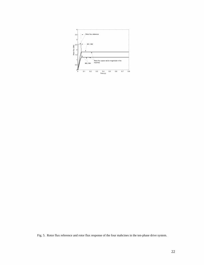
Excitation of all the four machines is initiated simultaneously, by ramping the rotor flux reference from
zero to twice the rated value in the time interval from zero to 0.01 s. The rotor flux reference is brought back to the
rated value (1.797 Wb for the ten-phase and 1.27 Wb for the five-phase machines) in the time interval from 0.05 to
0.06 s in the linear manner and is further kept unchanged. A forced excitation, leading to a faster build-up of the
rotor flux in the machines, is obtained in this way. Upon completion of the excitation transient, different torque
commands, of differing duration, are applied to the four machines in different time instants. Application and
removal of the torque command is in all the cases ramp-like, with the ramp duration of 0.01 s. Rated torque
command (16.667 Nm) is applied to the ten-phase machine (IM1) at 0.5 s and is removed at 0.7 s. A torque
command equal to 2/3 of the rated torque (i.e. 11.11 Nm) is applied to the second ten-phase machine (IM2) at 0.45
s and removal commences at 0.65 s. Rated torque command (8.33 Nm) is applied to the five-phase machine (IM3)
at 0.4 s and the removal is initiated at 0.65 s. Torque command for the second five-phase machine (IM4) is applied
at 0.3 and the removal starts at 0.55 s (¾ of the rated torque, i.e. 6.25 Nm). Load torque is zero for all machines.
Figure 5 shows rotor flux reference and the corresponding response of the rotor flux in the four machines.
Excitation process of any of the four machines is not disturbed in any way by the presence of the other machines in
the group. Rotor flux in any of the machines attains the reference value, confirming the absence of any x-y rotor
flux components. Upon completion of the excitation transient rotor flux remains at the constant value equal to the
reference, regardless of what happens with any of the four machines further on. Torque reference and torque
response (which are indistinguishable one from the other due to assumed ideal current feeding) are shown in Fig. 6.
Torque response of any of the four machines is not affected at all by the presence of the other machines.
Furthermore, torque control of any of the four machines is completely decoupled from the flux control. Thus not
only that full decoupled flux and torque control of any particular machine is achieved, but the completely
independent control of all the machines results as well, due to the introduced phase transposition, as predicted by
the theoretical considerations. Corresponding speed responses are shown in Fig. 7. They are perfectly smooth and
the fastest possible due to the achieved complete decoupling of the torque control of the four machines.
Stator phase current references for the four machines are illustrated by means of Fig. 8, where the traces
for phase ‘a’ are shown. They are of familiar waveform, met in the case of any vector controlled three-phase
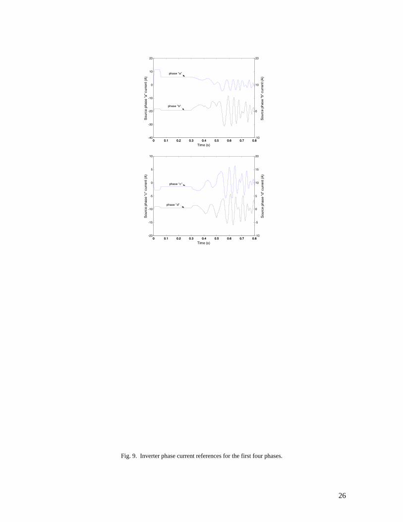
machine, and are sinusoidal in final steady states. However, total inverter current references, shown in Fig. 9 for the
first four phases of the inverter, are highly distorted since they are determined with the summation given in (12),
which accounts for the phase transposition.
Phase voltages of individual machines are illustrated for phase ‘a’ in Fig. 10. As can be seen from this
figure, phase voltages of all the four machines start changing at the instant of the application of the torque
command to IM4 (0. 3 s). Since IM4 is a five-phase machine, its acceleration affects all the other machines in the
group. The flow of x-y stator current components through the windings of all four machines is responsible for this.
Waveforms of phase voltages show a certain amount of distortion, caused by the series connection. It should be
noted that the two five-phase machines are affecting only one another, while the two ten-phase machines are
affected by all the other machines in the group.
Inverter output phase voltages, obtained by means of (14), are displayed in Fig. 11 for the first four phases.
They are heavily distorted since they represent an appropriate sum of four individual machine phase voltages, of
different fundamental frequencies and already having some amount of distortion due to the x-y components of the
machines’ phase voltages. However, generation of such distorted inverter voltage waveforms presents no difficulty

11
in practice, provided that fast inverter current control with a sufficiently high inverter switching frequency is used.
The practical questions of how much the dc link voltage should be, as a function of the machines’ rated voltages,
and how much the voltage reserve for good current control needs to be, are left for future investigation.
7. CONCLUSION
The paper develops a novel concept for a multi-motor drive system, which enables independent control of
a certain number of multi-phase machines with even numbers of phases, although the whole system is supplied
from a single current-controlled voltage source inverter. The stator multi-phase windings have to be connected in
series with an appropriate phase transposition, in order to achieve the independent control of the machines in the
system. The concept is developed in a systematic manner, using general theory of electrical machines, and is valid
regardless of the type of the ac machine, so that different machine types can be used within the same multi-motor
drive system. The necessary phase transposition in the stator winding connection is established by analysing the
properties of the decoupling transformation matrix and so-called connectivity matrix is formed for selected phase
numbers. Corresponding connection diagrams are further developed on the basis of the connectivity matrix. The
concept is in general applicable to any phase number greater than or equal to five. Considerations in this paper are
restricted to an even phase number. An even number of phases and the previous odd number enable, at best,
connection of the same number of machines in series and therefore the odd phase number saves a larger number of
inverter legs, compared to an equivalent three-phase drive system. However, as shown in the paper, an even phase
number always leads to a multi-motor system with at least two different phase numbers. All the machines in the
group with a smaller number of phases are not affected by series connection to the machines with a larger phase
number. The negative consequences of the series connection, discussed in the next paragraph, are therefore less
pronounced for an even phase number than for an odd phase number.
An obvious and major drawback of the concept is an increase in the stator winding losses due to the flow
of the flux/torque producing currents of all the machines through stator windings of some of the machines (note that
rotor winding losses are not affected). Similarly, stator iron losses will increase as well (although to a much lesser
extent), due to the increased phase voltage of the individual machines caused by the flow of x-y current
components. This will decrease the efficiency of the affected machines in the multi-motor system and will yield an
overall reduction in the total efficiency of the drive system, when compared to an equivalent three-phase
counterpart. Reduction in the efficiency is expected to be smaller for a system with an even phase number, when
compared to the equivalent multi-motor system with an odd phase number. In the ten-phase case considered in
detail, the two five-phase machines only affect one another, and do not suffer from any adverse effects caused by
connection to the two ten-phase machines. Of course, the two ten-phase machines are affected by the presence of all
the other machines.
It has to be noted that some of the advantages of the multi-phase machines, which exist in the case of a
single multi-phase motor drive, have been lost in the proposed multi-motor multi-phase system. For example,
torque density cannot be increased by injection of higher stator current harmonics, since all the available degrees of
freedom are used to control other machines in the group. Similarly, fault tolerance is completely lost for the same
reason.

12
All the possible even phase numbers are examined (disregarding the physical feasibility of large phase
numbers) in order to establish which of them offer a potential for connection of the largest number of machines. It
is shown that the maximum number of connectable machines results when the phase number n is either such that
n/2 is a prime number or is a power of two.
The concept is verified by simulation of a four-motor ten-phase drive system. Torque mode of operation is
examined and it is shown that completely decoupled and independent vector control of the four machines is
possible with the proposed series connection. The major advantage of such a multi-drive system is the saving in the
required number of inverter legs (when compared to an equivalent multi-motor three-phase drive), thus leading to
an increase in reliability. The ten-phase system requires ten inverter legs, while the corresponding four-motor three-
phase system would ask for twelve inverter legs. The other extremely useful feature of the concept is the easiness of
implementation within a single DSP. It is necessary to execute the required number of vector control algorithms in
parallel, calculate the individual motor phase current references, and then give at the output of the DSP inverter
current references, obtained by summation and respecting the connection diagram. Current control is further
executed in the stationary reference frame, using either hysteresis or ramp comparison inverter phase current
control.
8. ACKNOWLEDGEMENT
The authors gratefully acknowledge support provided for the work on this project by the EPSRC, under
the standard research grant number GR/R64452/01, and by Semikron Ltd. Mr. M. Jones acknowledges financial
support provided for his PhD studies by the IEE, through the IEE Robinson Research Scholarship.
13
9. REFERENCES [1] BELHADJ, J., BELKHODJA, I., DE FORNEL, B. and PIETRZAK-DAVID, M.: ‘DTC strategy for multi-
machine multi-inverter industrial system’. European Power Electronics and Applications Conference EPE, Graz, Austria, 2001, Paper no. PP01002.
[2] LEE, B.K., FAHIMI, B. and EHSANI, M.: ‘Overview of reduced parts converter topologies for ac motor drives’. IEEE Power Electronics Spec. Conf. PESC, Vancouver, Canada, 2001, pp. 2019-2024.
[3] LEDEZMA, E., McGRATH, B., MUOZ, A. and LIPO, T.A.: ‘Dual ac-drive system with a reduced switch count’, IEEE Trans. Industry Applications, 2001, 37, (5), pp. 1325-1333.
[4] JACOBINA, C.B., OLIVIERA, T.M., CORREA, M.B.deR., LIMA, A.M.N. and DA SILVA, E.R.C.: ‘Component minimized drive systems for multi-machine applications’. IEEE Power Electronics Spec. Conf. PESC, Cairns, Australia, 2002, Paper no. 10028.
[5] KUONO, Y., KAWAI, H., YOKOMIZO, S. and MATSUSE, K.: ‘A speed sensorless vector control method of parallel connected dual induction motor fed by a single inverter’. IEEE Ind. Appl. Soc. Annual Meeting IAS, Chicago, IL, 2001, Paper no. 29-04.
[6] MATSUMOTO, Y., OZAKI, S. and KAWAMURA, A.: ‘A novel vector control of single-inverter multiple-induction motors drives for Shinkansen traction system’. IEEE Applied Power Elec. Conf. APEC, Anaheim, CA, 2001, pp. 608-614.
[7] EGUILUZ, P., PIETRZAK-DAVID, M. and DE FORNEL, B.: ‘Comparison of several control strategies for parallel connected dual induction motors’. Power Electronics and Motion Control Conf. EPE-PEMC, Cavtat, Croatia, 2002, Paper no. T11-010.
[8] MA, J.D., WU, B., ZARGARI, N.R. and RIZZO, S.C.: ‘A space vector modulated CSI-based ac drive for multimotor applications’, IEEE Trans. Power Electronics, 2001, 16, (4), pp. 535-544.
[9] WARD, E.E. and HÄRER, H.: ‘Preliminary investigation of an invertor-fed 5-phase induction motor’, Proc. IEE, 1969, 116, (6), pp. 980-984.
[10] SINGH, G.K.: ‘Multi-phase induction machine drive research – a survey’, Electric Power Systems Research, 2002, 61, (2), pp. 139-147.
[11] JONES, M. and LEVI, E.: ‘A literature survey of state-of-the-art in multiphase AC drives’. Universities Power Engineering Conference UPEC, Stafford, UK, 2002, pp. 505-510.
[12] HODGE, C., WILLIAMSON, S. and SMITH, S.: ‘Direct drive propulsion motors’. Int. Conf. on Electrical Machines ICEM, Bruges, Belgium, 2002, Paper no. 087.
[13] GOLUBEV, A.N. and IGNATENKO, S.V.: ‘Influence of number of stator-winding phases on the noise characteristics of an asynchronous motor’, Russian Electrical Engineering, 2000, 71, (6), pp. 41-46.
[14] TOLIYAT, H.A., RAHIMIAN, M.M. and LIPO, T.A.: ‘A five phase reluctance motor with high specific torque’, IEEE Trans. Industry Applications, 1992, 28, (3), pp. 659-667.
[15] XU, H., TOLIYAT, H.A. and PETERSEN, L.J.: ‘Rotor field oriented control of a five-phase induction motor with the combined fundamental and third harmonic injection’. IEEE Applied Power Elec. Conf. APEC, Anaheim, CA, 2001, pp. 608-614.
[16] COATES, C.E., PLATT, D. and GOSBELL, V.J.: ‘Performance evaluation of a nine-phase synchronous reluctance drive’. IEEE Ind. Appl. Society Annual Meeting IAS, Chicago, IL, 2001, Paper no. 49-05.
[17] KESTELYN, X., SEMAIL, E. and HAUTIER, J.P.: ‘Vectorial multi-machine modeling for a five-phase machine’. Int. Conf. on Electrical Machines ICEM, Bruges, Belgium, 2002, Paper no. 394.
[18] GATARIC, S.: ‘A polyphase Cartesian vector approach to control of polyphase AC machines’. IEEE Ind. Appl. Soc. Annual Meeting IAS, Rome, Italy, 2000, Paper no. 38-02.
[19] LIPO, T.A.: ‘A Cartesian vector approach to reference frame theory of AC machines’. Int. Conf. on Electrical Machines ICEM, Lausanne, Switzerland, 1984, pp. 239-242.
[20] WHITE, D.C. and WOODSON, H.H.: ‘Electromechanical Energy Conversion’ (John Wiley and Sons, New York, NY, 1959).

14
10. APPENDIX
Per-phase equivalent circuit parameters of the 50 Hz five-phase and ten-phase induction motors:
H 42.0 H 04.0 3.6 10
===Ω=Ω=
mlrls
rs
LLLRR
Inertia and number of pole pairs: 2kgm 03.0=J , P = 2. Rated per-phase torque: 1.667 Nm. Rated rotor flux (RMS): 0.568 Wb. Rated per-phase voltage and current (RMS): 220 V and 2.1 A.
11. LIST OF PRINCIPAL SYMBOLS
v, i, ψ - voltage, current and flux linkage, respectively θs, θ - transformation angle for stator variables and rotor instantaneous angular position, respectively ωa, ω - angular speed of the common reference frame and angular electrical speed of rotor, respectively Rs, Rr - stator and rotor per-phase resistance Lls, Llr, Lm - stator and rotor per-phase leakage inductance, magnetising inductance P, Te - number of pole pairs and electromagnetic torque of the machine, respectively p - Laplace operator φr - instantaneous position of the rotor flux Indices: s, r - stator and rotor, respectively d, q - d-q axis components of voltages, currents and flux linkages in the common reference frame x, y - x-y components of voltages, currents and flux linkages o+, o- - zero sequence components of voltages, currents and flux linkages n - rated value

15
TABLES WITH NUMBERS AND TITLES
Table I. Connectivity matrix for the six-phase drive system.
A B C D E F M1 1 2 3 4 5 6 M2 1 3 5 1 3 5
Table II. Connectivity matrix for the eight-phase drive system.
A B C D E F G H M1 1 2 3 4 5 6 7 8 M2 1 3 5 7 1 3 5 7 M3 1 4 7 2 5 8 3 6
Table III. Connectivity matrix for the ten-phase drive system.
A B C D E F G H I J M1 1 2 3 4 5 6 7 8 9 10 M2 1 3 5 7 9 1 3 5 7 9 M3 1 4 7 10 3 6 9 2 5 8 M4 1 5 9 3 7 1 5 9 3 7
Table IV. Connectivity matrix for the twelve-phase system.
A B C D E F G H I J K L M1 1 2 3 4 5 6 7 8 9 10 11 12 M2 1 3 5 7 9 11 1 3 5 7 9 11 M3 1 4 7 10 1 4 7 10 1 4 7 10 M4 1 5 9 1 5 9 1 5 9 1 5 9 M5 1 6 11 4 9 2 7 12 5 10 3 8
Table V. Phase numbers of individual machines for the supply phase numbers up to eighteen.
Number of the supply phases
6 8 10 12 14 16 18
Number of phases and ordering of connectable
machines (before re-ordering)
6 3
8 4 8
10 5
10 5
12 6 4 3
12
14 7
14 7
14 7
16 8
16 4
16 8
16
18 9 6 9 18 3 18 9
16
Table VI. Connectivity matrix for the twenty-phase drive system. A B C D E F G H I J K L M N O P Q R S T M1 1 2 3 4 5 6 7 8 9 10 11 12 13 14 15 16 17 18 19 20 M2 1 3 5 7 9 11 13 15 17 19 1 3 5 7 9 11 13 15 17 19 M3 1 4 7 10 13 16 19 2 5 8 11 14 17 20 3 6 9 12 15 18 M4 1 5 9 13 17 1 5 9 13 17 1 5 9 13 17 1 5 9 13 17 M5 1 6 11 16 1 6 11 16 1 6 11 16 1 6 11 16 1 6 11 16 M6 1 7 13 19 5 11 17 3 9 15 1 7 13 19 5 11 17 3 9 15 M7 1 8 15 2 9 16 3 10 17 4 11 18 5 12 19 6 13 20 7 14 M8 1 9 17 5 13 1 9 17 5 13 1 9 17 5 13 1 9 17 5 13 M9 1 10 19 8 17 6 15 4 13 2 11 20 9 18 7 16 5 14 3 12
Table VII. Number of connectable machines and their phase order for an even system phase number.
n = an even number, ≥ 6 Number of connectable machines Number of phases of
machines n/2 = prime
number
22−
=nk
k/2 are n-phase and k/2 are n/2-phase
n/2 ≠ prime number
.....5,4,3 , 2 == mn m 2
2−=
nk 22 2
......., ,2
,2
,−m
nnnn
all other even numbers 2
2−<
nk n, ....4/,3/,2/ nnn
as appropriate

17
LIST OF FIGURE CAPTIONS
Fig. 1. Connection diagram for the six-phase two-motor system.
Fig. 2. Connection diagram for the eight-phase drive system.
Fig. 3. Series connection of two ten-phase and two five-phase machines to the ten-phase source.
Fig. 4. Indirect vector controller for an n-phase induction motor (K1 = )(1 **dsr iT ).
Fig. 5. Rotor flux reference and rotor flux response of the four mahcines in the ten-phase drive system.
Fig. 6. Torque references and torque responses of the four machines.
Fig. 7. Speed responses of the four-motor drive system.
Fig. 8. Phase ‘a’ current references of the four machines.
Fig. 9. Inverter phase current references for the first four phases.
Fig. 10. Stator phase ‘a’ voltages of the four machines.
Fig. 11. Inverter output phase voltages for the first four phases.

18
A
B
C
D
E
F
Source
a1
b1
c1
d1
e1
f1
a2
b2
c2
Machine 1 Machine 2
Fig. 1. Connection diagram for the six-phase two-motor system.
19
Fig. 2. Connection diagram for the eight-phase drive system.
A
B
C
D
E
F
G
H
a1
b1
c1
d1
e1
f1
g1
h1
a2
b2
c2
d2
e2
f2
g2
h2
a3
b3
c3
d3
Source Machine 1 Machine 2 Machine 3
20
A
B
C
D
E
F
G
H
I
J
Source
a1
b1
c1
d1
e1
f1
g1
h1
i1
j1
a2
b2
c2
d2
e2
f2
g2
h2
i2
j2
Machine 1 Machine 2
a3
b3
c3
d3
e3
Machine 3
a4
b4
c4
d4
e4
Machine 4
Fig. 3. Series connection of two ten-phase and two five-phase machines to the ten-phase source.

21
PI
K1
1/p
jφr
e
2 n
i1*
i2*
i3*
in*
ids* = idsn
iqs* ω*
p
P
θ
φr
ω
ωsl*
Fig. 4. Indirect vector controller for an n-phase induction motor (K1 = )(1 **dsr iT ).
22
0 0.1 0.2 0.3 0.4 0.5 0.6 0.7 0.80
0.5
1
1.5
2
2.5
3
3.5
4
Time (s)R
otor
flu
x (W
b)
Rotor flux reference
IM1, IM2
Rotor flux space vector magnitude in the machineIM3, IM4
Fig. 5. Rotor flux reference and rotor flux response of the four mahcines in the ten-phase drive system.

23
0 0.1 0.2 0.3 0.4 0.5 0.6 0.7 0.8-2
0
2
4
6
8
10
12
14
16
18
Time (s)T
orqu
e (N
m)
IM1
IM2
IM3
IM4
Fig. 6. Torque references and torque responses of the four machines.

24
0 0.1 0.2 0.3 0.4 0.5 0.6 0.7 0.8-200
0
200
400
600
800
1000
1200
Time (s)S
peed
(rp
m)
IM1
IM2
IM3
IM4
Fig. 7. Speed responses of the four-motor drive system.

25
0 0.1 0.2 0.3 0.4 0.5 0.6 0.7 0.8-9
-6
-3
0
3
Time (s)
Sta
tor
phas
e "a
" cu
rren
t re
fere
nce
IM1
(A)
0 0.1 0.2 0.3 0.4 0.5 0.6 0.7 0.8-3
0
3
6
9
Sta
tor
phas
e "a
" cu
rren
t re
fere
nce
IM2
(A)
IM1
IM2
0 0.1 0.2 0.3 0.4 0.5 0.6 0.7 0.8-9
-6
-3
0
3
Time (s)
Sta
tor
phas
e "a
" cu
rren
t re
fere
nce
IM3
(A)
0 0.1 0.2 0.3 0.4 0.5 0.6 0.7 0.8-3
0
3
6
9
Sta
tor
phas
e "a
" cu
rren
t re
fere
nce
IM4
(A)
IM3
IM4
Fig. 8. Phase ‘a’ current references of the four machines.
26
0 0.1 0.2 0.3 0.4 0.5 0.6 0.7 0.8-40
-30
-20
-10
0
10
20
Time (s)S
ourc
e ph
ase
"a"
curr
ent (
A)
0 0.1 0.2 0.3 0.4 0.5 0.6 0.7 0.8-10
0
10
20
Sou
rce
phas
e "b
" cu
rren
t (A
)
phase "a"
phase "b"
0 0.1 0.2 0.3 0.4 0.5 0.6 0.7 0.8-20
-15
-10
-5
0
5
10
Time (s)
Sou
rce
phas
e "c
" cu
rren
t (A
)
0 0.1 0.2 0.3 0.4 0.5 0.6 0.7 0.8-10
-5
0
5
10
15
20
Sou
rce
phas
e "d
" cu
rren
t (A
)
phase "c"
phase "d"
Fig. 9. Inverter phase current references for the first four phases.

27
0 0.1 0.2 0.3 0.4 0.5 0.6 0.7 0.8-800
-600
-400
-200
0
200
400
Time (s)
Sta
tor
phas
e "a
" vo
ltage
IM
1 (V
)
0 0.1 0.2 0.3 0.4 0.5 0.6 0.7 0.8-200
0
200
400
600
800
Sta
tor
phas
e "a
" vo
ltage
IM
2 (V
)
IM1
IM2
0 0.1 0.2 0.3 0.4 0.5 0.6 0.7 0.8-600
-400
-200
0
200
Time (s)
Sta
tor
phas
e "a
" vo
ltage
IM
3 (V
)
0 0.1 0.2 0.3 0.4 0.5 0.6 0.7 0.8-200
0
200
400
600
Sta
tor
phas
e "a
" vo
ltage
IM
4 (V
)
IM3
IM4
Fig. 10. Stator phase ‘a’ voltages of the four machines.

28
0 0.1 0.2 0.3 0.4 0.5 0.6 0.7 0.8-2200
-1200
-200
800
Time (s)S
ourc
e ph
ase
"a"
volta
ge (
V)
0 0.1 0.2 0.3 0.4 0.5 0.6 0.7 0.8-500
0
500
1000
1500
Sou
rce
phas
e "b
" vo
ltage
phase "a"
phase "b"
0 0.1 0.2 0.3 0.4 0.5 0.6 0.7 0.8-1800
-1500
-1200
-900
-600
-300
0
300
600
Time (s)
Sou
rce
phas
e "c
" vo
ltage
(V
)
0 0.1 0.2 0.3 0.4 0.5 0.6 0.7 0.8-600
-300
0
300
600
900
1200
1500
1800
Sou
rce
phas
e "d
" vo
ltage
(V
)
phase "c"
phase "d"
Fig. 11. Inverter output phase voltages for the first four phases.


![Electrical Machines Laboratory - Terco [Swedish]...DC-Machine 6,8 DC-Motor Drive Single Phase 25 DC-Motor Drive 3-phase 26 Digital Torque-, Speed- and Shaft Power Meter MV1054 5 Documentation](https://img.pdfslide.us/doc/110x75/612273ec6a45b223526528c5/electrical-machines-laboratory-terco-swedish-dc-machine-68-dc-motor-drive.jpg)