Embed Size (px)
Citation preview

An Efficient Turbo Equalization for Faster than
Nyquist Signal
Chang-Uk Baek and Ji-Won Jung Radio Communication Engineering, Korea Maritime and Ocean University, Busan, Korea
Email: {cubaek, jwjung}@kmou.ac.kr
Abstract—In this paper, we analyzed efficient decoding
scheme with faster than Nyquist (FTN) signaling that is
transmission method faster than Nyquist theory and
increase the throughput. We proposed BCJR equalization
model to minimize inter symbol interference when faster
than Nyquist signal is transmitted. The presented model
utilized interference as branch information and iteratively
exchange probabilistic information between BCJR and
LDPC decoder. In BCJR equalizer, the performance
depends on Euclidean distance of branch metrics between
possible transitions at each node, in order to maximize
Euclidean distances, we proposed FTN re-mapper by
reordering the branch matrices on trellis diagram. We
confirmed that performance was improved compared to
conventional methods as increasing throughput of fast than
Nyquist signal.
Index Terms—faster than Nyquist, BCJR equalizer, LDPC
codes
I. INTRODUCTION
Faster-Than-Nyquist (FTN) signalling is a technique of
transmitting information at a rate higher than the allowed
Nyquist limit [1]-[4]. Systems employing this technique
have shown to achieve higher information rates at the
cost of increased processing in the transmitter and the
receiver. There have been some efforts to apply FTN
theory to commercial applications, e.g. DVB-S2 for the
satellite broadcasting system. It evaluated the
performance of DVB-S2 building block based on FTN
transmission, and this result gives an opportunity for the
practical implementation. There is increasingly growing
demand to send high data rates over satellite channels.
We here discuss utilizing time packing or FTN signalling
to satisfy this demand in combination with using tight
frequency spacing is (1+ )s
α R , where s
R is the symbol
rate and is roll-off factor. In FTN signalling,
information symbols are transmitted at a rate higher than
that suggested by the Nyquist criterion, i.e., 1/ > 2τ W
and, therefore, ISI is unavoidable. Signaling above the
Nyquist rate comes at the expense of higher receiver
complexity and higher transmitted power, since more
information symbols are sent per second. Since it was
first studied, the usefulness of FTN has not yet been
determined. Several receivers have been suggested, some
Manuscript received October 21, 2014; revised June 25, 2015.
implying the feasibility of FTN and others not
considering it worthwhile. The presented model utilized
interference as branch information and iteratively
exchange probabilistic information between BCJR
equalizer and LDPC decoder [5]-[8]. In BCJR equalizer,
the performance depends on Euclidean distance of branch
metrics between possible transitions at each node, in
order to maximize Euclidean distances, we proposed FTN
re-mapper by reordering the branch matrices on trellis
diagram. We confirmed that performance was improved
compared to conventional methods as increasing
throughput of FTN signal.
II. FTN SIGNAL MODELING
With this background, we turn to FTN signalling. The
key aspect of the FTN method is that ( )h t is no longer
orthogonal with respect to the symbol time. The same h
is employed but the symbol time is , < 1τT τ . The signal
becomes:
( ) ( )s nns t = E α h t - nτT (1)
here n
is a sequence of independent M-ary data
symbols, each with energy s
E , and a new unit-energy
pulse are ( )h t appears each T seconds, the symbol time.
The factor τ can be thought of as a time acceleration
factor since now the pulses come too fast by a factor 1/τ .
If a filter matched to ( )h t is used in the detection, its
samples are no longer the M-ary values n
a plus noise,
but contain inter symbol interference (ISI) as well.
Above is ordinary orthogonal linear modulation with
( ) = sinh t T /πt πt/T , with the lighter sinc pulses
representing symbols -1, +1, -1, +1, +1… that add up to
the heavier curve ( )s t .
(a) Nyquist rate data (T=1 and τ=1)
International Journal of Signal Processing Systems Vol. 4, No. 3, June 2016
©2016 Int. J. Sig. Process. Syst. 231doi: 10.18178/ijsps.4.3.231-234

(b) Faster than Nyquist rate data (T=1 and τ=0.8)
Figure 1. Illustration of FTN signaling with unit-T sinc pulses and τ=1 and 0.8
Fig. 1 shows an example of FTN signal with
orthogonal symbol time = 1τ and 0.8 . Fig. 1(a) is
ordinary signal with Nyquist rate, and Fig. 1(b) shows
FTN signal with 0.8 . It can be seen than five sinc
pulses are now advanced.
III. AN EFFICIENT DECODER STRUCTURE FOR FTN
MODEL
Fig. 2 displays FTN transmission system based on
DVB-S2 standards. Let us suppose that the binary digits
delivered by source are encoded by a LDPC encoder. The
encoded data are reordered by an interleaver, and applied
QPSK modulation point with FTN mapper. At the
receiver side, an LLR computer is needed to convert the
equalizer output, assumed to follow Gaussian distribution,
into extrinsic LLRs regarding the code bits, by using a
priori LLRs from the previous decoding iteration. This
updated set of soft information about the code bits is then
deinterleaved and provided as a priori LLRs, for the next
decoding iteration.
Figure 2. FTN re-mapper
The computation of the LLRs pertaining to the
equalizer uses the FTN rate and roll-off values in
reconstructing ISI in each carrier. Generally, the decoding
method of trellis type as shown in Fig. 2 is BCJR
algorithm [9], [10] with soft decision value. BCJR
algorithm is a well-known maximum a posteriori
probability decoding algorithm which has been proposed
earlier for point to point communication applications.
The value of D
eL after interleaver is computed as
I I
e cL - L , then input to the turbo decoder. The estimated
extrinsic value of D
c at decoder output is given by:
( = +1)= log
( = -1)
D
c
p xL
p x 2
The extrinsic value D
cL of which calculates the post
probability is error correction terms. The re-interleaving
of computed value as D D
c eL - L is input to BCJR equalizer,
then I
cL is updated in order to compensate for the errors.
Fig. 3 shows block diagram of FTN mapper. As shown
in Equation (1), take into account acceleration factor
and M interference signal at time k, quantities may be
written in the form:
-1
=0( ) = ( - )
M
k mmΓ t α h t mτT (3)
And let us suppose that ISI is limited (L1+L2) symbols.
Equation (1) may be written in the form:
1
2-=-
= ( ) +L
t k t k tk LR Γ t c b (4)
Figure 3. Equivalent discrete-time model of a channel with inter-symbol interference
tb is zero mean white Gaussian noise with power
spectrum density equal to N0. If we denote
2 1+ - +1= , ,n n L n LS c L c the state of the equivalent
discrete-time channel at time nT , sample n
R depends on
the channel state 1n-
S and on the symbol 2n+L
c . Therefore,
the equivalent discrete-time channel can be modelled as a
Markov chain and its behaviour can be represented by a
trellis diagram (Fig. 2). Where, xyzb is branch metrics for
current symbol y in aspect to previous symbol z and next
symbol x. Also, xyzb is the same as transmitted FTN
signal for y. Based on τ=0.8 and L1=L2=1, xyzb are
defined in Table I.
TABLE I. xyz
b VALUES (Τ=0.8, L1=1, L2=1)
x y z xyz
b
0 0 0 -1.390080
0 0 1 -1.095634
0 1 0 0.801187
0 1 1 1.095634
1 0 0 -1.095634
1 0 1 -0.81187
1 1 0 1.095634
1 1 1 1.390080
Based on Fig. 4(a) and Table I, the Euclidean distance
between branch metrics at each node is very small. In
BCJR equalizer, the performance depends on Euclidean
International Journal of Signal Processing Systems Vol. 4, No. 3, June 2016
©2016 Int. J. Sig. Process. Syst. 232
L
distance of branch metrics between possible transitions at
each node, in order to maximize Euclidean distances, we
proposed FTN re-mapper by changing the trellis diagram.
In xyzb , Euclidean distance is depended on y symbols.
Therefore, FTN re-mapper reconstruct trellis diagram as
shown in Fig. 4(b). To maximize Euclidean distance, we
change
(a) FTN mapper (b) FTN re-mapper
Figure 4. Trellis diagram
A set of triples (previous state, channel output, next
state) uniquely defines a finite state machine on which the
BCJR operates. As an illustration a trellis is shown in Fig.
3(c). It has 4 states 0 1 3, , ,s s L s , and each state is given
by a different 2-bit pattern. The states in vertical columns
represent all possible states that the channel (or FSM) can
take at a given time instant, while the labeled edges
represent possible transitions. Neighboring columns thus
represent consecutive time instants.
Given s' the previous state,
+1 +1= , , , , , ,j-m j-m j j j+ms c c L c c L c - the present state,
1 2= , , , nu u u L u - the transmitted code word, and
1 2= , , , ny y y L y - the received sequence, the log-
likelihood ratio (LLR) (denoting the bit reliability) of
( =1, 2, ..., )ju j n , is calculated as:
*
-1= max + , +
j j j jL u α s γ s s β s ,s s = 1
ju
*
-1-max + , +
j j jα s γ s s β s ,s s =1ju (5)
The forward metric, 1log = ,
j
j jα s = p s s y is given
by:
*
-1( ) = max ,
j j jα s α s +γ s s (6)
The backward metric, +1=
n
j jβ s = logp y | s s as:
*
-1= max ,
j j jβ (s ) β s +γ s s (7)
And the branch metric ,jγ s s is given by:
-1, = log = , =j j j jγ s s p s s y | s s (8)
= logj j
p y | u jp u
The *max - operator is defined as:
*max max( , ) + log
x- yx, y = x y 1+e (9)
LDPC decoder and BCJR equalizer are connected
through the interleaving and de-interleaving that update
each other’s information repeatedly. The inner coded bits
are then subtracted from the input and interleaved. The
interleaved output is cancelled a posteriori from the
proceeding received signal. Interleaving helps receiver
convergence.
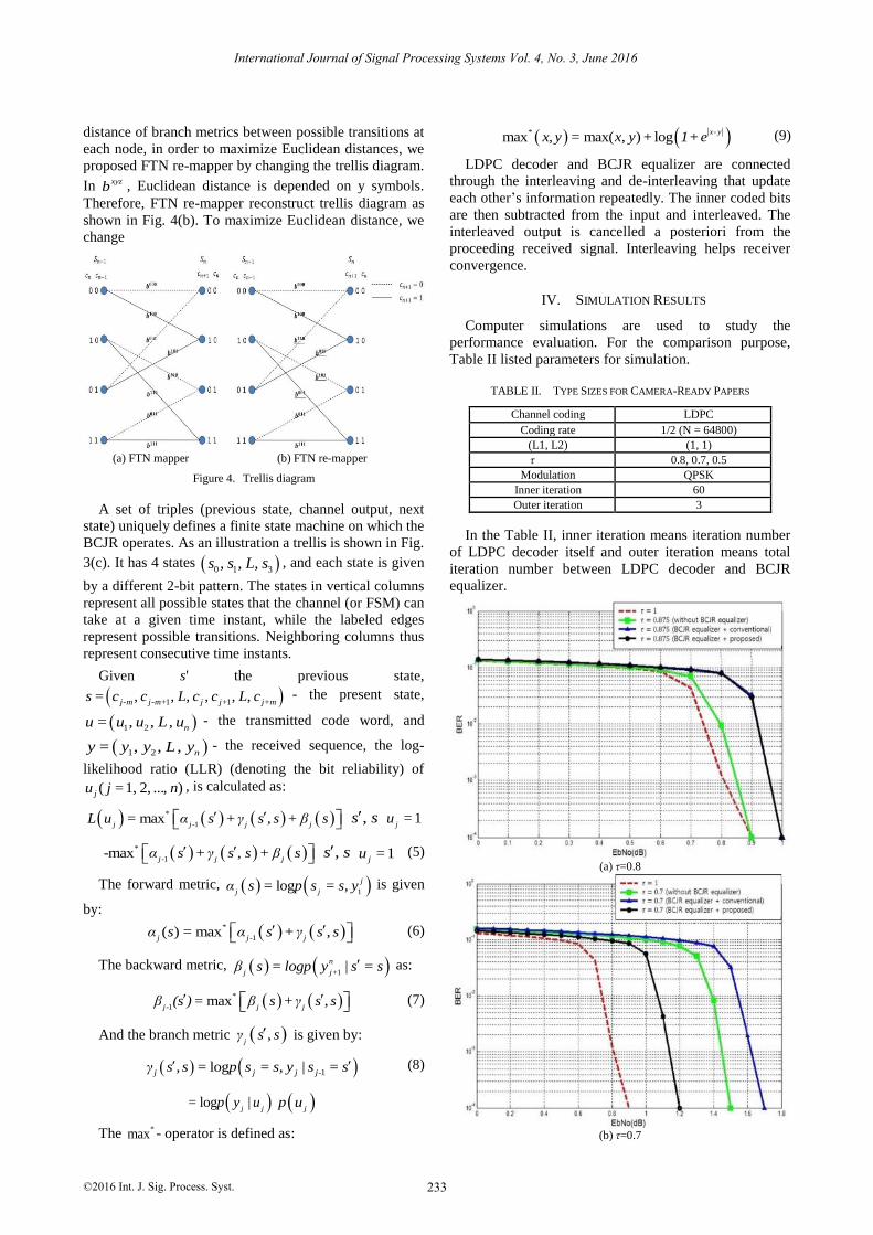
IV. SIMULATION RESULTS
Computer simulations are used to study the
performance evaluation. For the comparison purpose,
Table II listed parameters for simulation.
TABLE II. TYPE SIZES FOR CAMERA-READY PAPERS
Channel coding LDPC
Coding rate 1/2 (N = 64800)
(L1, L2) (1, 1)
τ 0.8, 0.7, 0.5
Modulation QPSK
Inner iteration 60
Outer iteration 3
In the Table II, inner iteration means iteration number
of LDPC decoder itself and outer iteration means total
iteration number between LDPC decoder and BCJR
equalizer.
(a) τ=0.8
(b) τ=0.7
International Journal of Signal Processing Systems Vol. 4, No. 3, June 2016
©2016 Int. J. Sig. Process. Syst. 233
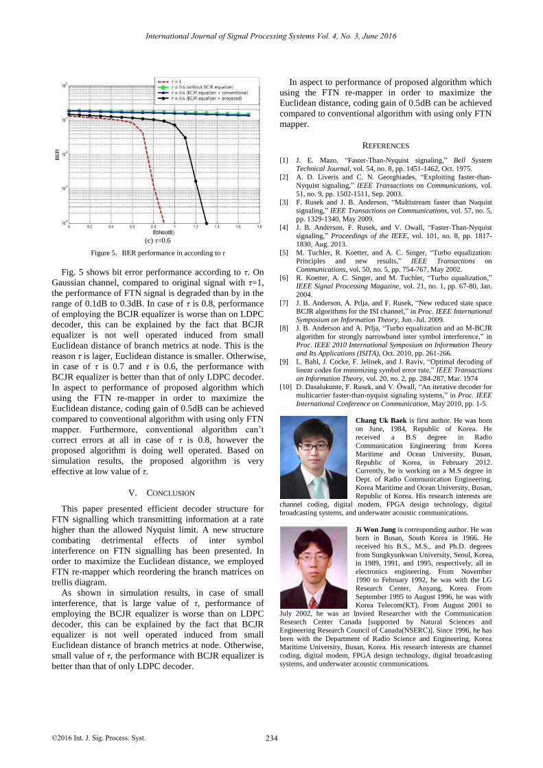
(c) τ=0.6
Figure 5. BER performance in according to τ
Fig. 5 shows bit error performance according to τ. On
Gaussian channel, compared to original signal with τ=1,
the performance of FTN signal is degraded than by in the
range of 0.1dB to 0.3dB. In case of τ is 0.8, performance
of employing the BCJR equalizer is worse than on LDPC
decoder, this can be explained by the fact that BCJR
equalizer is not well operated induced from small
Euclidean distance of branch metrics at node. This is the
reason τ is lager, Euclidean distance is smaller. Otherwise,
in case of τ is 0.7 and τ is 0.6, the performance with
BCJR equalizer is better than that of only LDPC decoder.
In aspect to performance of proposed algorithm which
using the FTN re-mapper in order to maximize the
Euclidean distance, coding gain of 0.5dB can be achieved
compared to conventional algorithm with using only FTN
mapper. Furthermore, conventional algorithm can’t
correct errors at all in case of τ is 0.8, however the
proposed algorithm is doing well operated. Based on
simulation results, the proposed algorithm is very
effective at low value of τ.
V. CONCLUSION
This paper presented efficient decoder structure for
FTN signalling which transmitting information at a rate
higher than the allowed Nyquist limit. A new structure
combating detrimental effects of inter symbol
interference on FTN signalling has been presented. In
order to maximize the Euclidean distance, we employed
FTN re-mapper which reordering the branch matrices on
trellis diagram.
As shown in simulation results, in case of small
interference, that is large value of τ, performance of
employing the BCJR equalizer is worse than on LDPC
decoder, this can be explained by the fact that BCJR
equalizer is not well operated induced from small
Euclidean distance of branch metrics at node. Otherwise,
small value of τ, the performance with BCJR equalizer is
better than that of only LDPC decoder.
In aspect to performance of proposed algorithm which
using the FTN re-mapper in order to maximize the
Euclidean distance, coding gain of 0.5dB can be achieved
compared to conventional algorithm with using only FTN
mapper.
REFERENCES
[1] J. E. Mazo, “Faster-Than-Nyquist signaling,” Bell System
Technical Journal, vol. 54, no. 8, pp. 1451-1462, Oct. 1975. [2] A. D. Liveris and C. N. Georghiades, “Exploiting faster-than-
Nyquist signaling,” IEEE Transactions on Communications, vol.
51, no. 9, pp. 1502-1511, Sep. 2003. [3] F. Rusek and J. B. Anderson, “Multistream faster than Nuquist
signaling,” IEEE Transactions on Communications, vol. 57, no. 5, pp. 1329-1340, May 2009.
[4] J. B. Anderson, F. Rusek, and V. Owall, “Faster-Than-Nyquist
signaling,” Proceedings of the IEEE, vol. 101, no. 8, pp. 1817-1830, Aug. 2013.
[5] M. Tuchler, R. Koetter, and A. C. Singer, “Turbo equalization: Principles and new results,” IEEE Transactions on
Communications, vol. 50, no. 5, pp. 754-767, May 2002.
[6] R. Koetter, A. C. Singer, and M. Tuchler, “Turbo equalization,” IEEE Signal Processing Magazine, vol. 21, no. 1, pp. 67-80, Jan.
2004. [7] J. B. Anderson, A. Prlja, and F. Rusek, “New reduced state space
BCJR algorithms for the ISI channel,” in Proc. IEEE International
Symposium on Information Theory, Jun.-Jul. 2009. [8] J. B. Anderson and A. Prlja, “Turbo equalization and an M-BCJR
algorithm for strongly narrowband inter symbol interference,” in Proc. IEEE 2010 International Symposium on Information Theory
and Its Applications (ISITA), Oct. 2010, pp. 261-266.
[9] L. Bahl, J. Cocke, F. Jelinek, and J. Raviv, “Optimal decoding of linear codes for minimizing symbol error rate,” IEEE Transactions
on Information Theory, vol. 20, no. 2, pp. 284-287, Mar. 1974 [10] D. Dasalukunte, F. Rusek, and V. Owall, “An iterative decoder for
multicarrier faster-than-nyquist signaling systems,” in Proc. IEEE
International Conference on Communication, May 2010, pp. 1-5.
Chang Uk Baek is first author. He was born on June, 1984, Republic of Korea. He
received a B.S degree in Radio
Communication Engineering from Korea Maritime and Ocean University, Busan,
Republic of Korea, in February 2012. Currently, he is working on a M.S degree in
Dept. of Radio Communication Engineering,
Korea Maritime and Ocean University, Busan, Republic of Korea. His research interests are
channel coding, digital modem, FPGA design technology, digital broadcasting systems, and underwater acoustic communications.
Ji Won Jung is corresponding author. He was born in Busan, South Korea in 1966. He
received his B.S., M.S., and Ph.D. degrees
from Sungkyunkwan University, Seoul, Korea, in 1989, 1991, and 1995, respectively, all in
electronics engineering. From November 1990 to February 1992, he was with the LG
Research Center, Anyang, Korea. From
September 1995 to August 1996, he was with Korea Telecom(KT). From August 2001 to
July 2002, he was an Invited Researcher with the Communication Research Center Canada [supported by Natural Sciences and
Engineering Research Council of Canada(NSERC)]. Since 1996, he has
been with the Department of Radio Science and Engineering, Korea Maritime University, Busan, Korea. His research interests are channel
coding, digital modem, FPGA design technology, digital broadcasting systems, and underwater acoustic communications.
International Journal of Signal Processing Systems Vol. 4, No. 3, June 2016
©2016 Int. J. Sig. Process. Syst. 234


![LMMSE turbo equalization based on factor graphsliping/Research/Journal/53... · factor graphs, Gaussian message passing, linear MMSE. I. INTRODUCTION T URBO equalization [1]-[8] is](https://img.pdfslide.us/doc/110x75/6007243dfe2d385f6d5d46ad/lmmse-turbo-equalization-based-on-factor-lipingresearchjournal53-factor.jpg)


![Turbo equalization: principles and new results ...singer/pub_files/Turbo...Combined turbo codingand equalization [20],[21]includes threeor morelayers: two or more coding layers as](https://img.pdfslide.us/doc/110x75/600724985f3e7f70086519b2/turbo-equalization-principles-and-new-results-singerpubfilesturbo-combined.jpg)