Embed Size (px)
Citation preview

i
An Efficient Handoff Scheme for WiMAX
Networks with Load Balancing
Mays Kareem Jabbar Al Sabah
Submitted to the
Institute of Graduate Studies and Research
in partial fulfillment of the requirements for the Degree of
Master of Science
in
Computer Engineering
Eastern Mediterranean University
June 2014
Gazimağusa, North Cyprus

ii
Approval of the Institute of Graduate Studies and Research
Prof. Dr. Elvan Yılmaz
Director
I certify that this thesis satisfies the requirements as a thesis for the degree of Master
of Science in Computer Engineering.
Prof. Dr. Işık Aybay
Chair, Department of Computer Engineering
We certify that we have read this thesis and that in our opinion it is fully adequate in
scope and quality as a thesis for the degree of Master of Science in Computer
Engineering.
Assoc. Prof. Dr. Muhammed Salamah
Supervisor
Examining Committee
1. Assoc. Prof. Dr. Hasan Demirel
2. Assoc. Prof. Dr. Muhammed Salamah
3. Asst. Prof. Dr. Gürcü Öz

iii
ABSTRACT
The IEEE 802.16e-2005 standard Mobile WiMAX is the technology which provides
wireless access to hundreds of users over long distances with high data rates. The
Mobile users may have high mobility; to support this mobility and guarantee
continuous connection in Mobile WiMAX when the mobile station travels far from
the coverage area of its servicing base station, WiMAX must support handoff.
Handoff is the process of switching between the base stations. During the period of
the handoff process, the mobile station leaves the connection with the serving base
station and hence leads to temporarily stopping running services. The efficiency of
the mobile wireless network is affected by the handoff latency which occurs during
the handoff process, as a result of scanning, ranging with the neighbor base stations
and authentication, and registration with the target base station.
In this thesis, we propose a new handoff scheme for Mobile WiMAX using the
handoff prediction table in order to minimize the handoff latency and also balance
the load between base stations. The handoff prediction table is used to expect the
next base station, so the mobile station does not need to scan all neighboring base
stations.”
Performance analyses of the proposed scheme were carried out and the results show
that our proposed scheme can decrease the latency compared with the standard
WiMAX and other previously proposed schemes. Also, the results show that load
balancing can be achieved between base stations by using the proposed scheme.
Keywords: WiMAX, Handoff, Handoff prediction table, Handoff latency.

iv
ÖZ
IEEE 802.16e-2005 standard "Mobil WiMAX", yüzlerce kullanıcıya yüksek veri
oranları ile uzak mesafelere kablosuz erişim sağlayan bir teknolojidir. Mobil
kullanıcıları yüksek hareketliliğe sahip olabilir; mobil istasyonu baz istasyonunun
kapsama alanından bir diğerine hareket ederken bu hareketliliği desteklemek ve
Mobil WiMAX ile sürekli bağlantıyı garantilemek için, WiMAX transferini
desteklemesi gerekir. Transfers baz istasyonları arasında geçiş yapma işlemidir.
Transfer işlemi sırasında, mobil istasyon hizmet veren ana istasyon ile bağlantıyı
koparır ve dolayısıyla geçici olarak sağlanan hizmetin durdurulmasına yol açar.
Mobil telsiz ağının verimliliği, transfer işlemi sırasında ortaya çıkan gecikmeden
etkilenir. Bu gecikmeler, tarama, komşu baz istasyonla kimlik doğrulama, ve hedef
baz istasyon ile kayıt yapma işlemlerden dolayı ortaya çıkmaktadır.
Bu tezde, geciden dolayı ortaya çıkan gecikmeyi en aza indirgemek ve geçis tahmin
tablosunu kullanarak baz istasyonları arasındaki yükü dengeleme amacıyla Mobil
WiMAX için yeni bir geçis düzeni önerilmektedir. Geçis tahmin tablosu bir sonraki
ana istasyonu belirlemek için kullanılmakta ve bu nedenle mobil istasyonun tüm
komşu baz istasyonlarını taramasına gerek olmamaktadır.
Önerilen düzenin performans analizleri yapılmış ve elde edilen sonuçlara gore, tez
çalışmasında önerilen düzenin standart WiMAX ve daha once varolan diğer
düzenlerle karşılaştırılması sonucu, önerilen düzenin gecikmeyi azaltmakta etkili
olduğunu göstermektedir. Ayrıca, sonuçlar, önerilen düzen kullanılmasının, baz
istasyonları arasında yük dengelemesinde olumlu etki yapacağını göstermektedir.

v
Anahtar Kelimeler: WiMAX, Geçis, Geçis tahmin tablosunu, Geçis gecikmesi.

vi
DEDICATION
To my lovely son (Hasan), who shared with me all moments and
all the difficulties that I faced during my studies.

vii
ACKNOWLEDGMENT
Firstly, I am highly thankful to my thesis supervisor in the person of the Assoc. Prof.
Dr. Muhammed Salamah for helping me to complete my thesis, his support and
persistent encouragement helped me to overcome the difficulties that I faced during
studying my research.
I express my deepest love and gratitude to my husband (Thaar) who encouraged and
supported me and offered me endless love and care, without his support I could not
be able to finish my studies.
Also, special thanks and appreciation to my great father (Eng. Kareem Al Sabah) and
my wonderful mother (Khawla) for their encouragement and continuous mental
support. In fact, they made me successful in my life.
Finally, I would like to extend my thanks to my brothers (Yasir and Al Hussain) and
my lovely sister (Maryam) for their support and love toward me.

viii
TABLE OF CONTENTS
ABSTRACT ................................................................................................................ iii
ÖZ ............................................................................................................................... iv
DEDICATION ........................................................................................................... vi
ACKNOWLEDGMENT ............................................................................................ vii
LIST OF TABLES ....................................................................................................... x
LIST OF FIGURES .................................................................................................... xi
LIST OF ABBREVIATIONS ................................................................................... xiii
1 INTRODUCTION ..................................................................................................... 1
1.1 Background ........................................................................................................ 1
1.2 WiMAX Standards ............................................................................................. 3
1.3 WiMAX vs. Wi-Fi .............................................................................................. 5
1.4 Motivation .......................................................................................................... 5
1.5 Objectives ........................................................................................................... 6
1.6 Thesis Outline .................................................................................................... 7
2 LITERATURE REVIEW .......................................................................................... 8
2.1 WiMAX Layers .................................................................................................. 8
2.1.1 Physical Layers ........................................................................................... 9
2.1.2 Mobile WiMAX MAC Layer.................................................................... 14
2.2 Handoff in Mobile WiMAX ............................................................................. 21
2.2.1 Handoff Initialization ................................................................................ 22
2.2.2 Handoff Decision ...................................................................................... 24
2.2.3 Handoff Types in WiMAX ....................................................................... 25
2.2.4 Mobile WiMAX Handoff Phases .............................................................. 28

ix
2.3 Related Works .................................................................................................. 32
3 THE PROPOSED HANDOFF SCHEME............................................................... 34
3.1 A Scenario to Demonstrate the Proposed Scheme ........................................... 38
4 SIMULATION RESULTS ...................................................................................... 40
4.1 Handoff Latency ............................................................................................... 43
4.2 Overhead SMS Messages and the Dropping Probability ................................. 48
4.3 Load Balancing ................................................................................................ 49
4.4 Comparison with other Studies ........................................................................ 51
5 CONCLUSION ....................................................................................................... 55
REFERANCES .......................................................................................................... 55
APPENDICES ........................................................................................................... 61
Appendix A: Confidence Intervals......................................................................... 62
Appendix B: MATLAB Code ................................................................................ 64

x
LIST OF TABLES
Table 1.1: Summaries of IEEE802.16 Standards [7] ................................................... 4
Table 1.2: WiMAX vs. Wi-Fi ...................................................................................... 5
Table 2.1: OFDMA Scalability Parameters [10]........................................................ 10
Table 2.2: PHY-layer data rate at different channel bandwidths [1] ........................ 14
Table 2.3: Service Classes Supported in WiMAX [1] ............................................... 18
Table 3.1: Example of the HO prediction table ......................................................... 35
Table 3.2: The HO prediction table of BS7 ............................................................... 39
Table 4.1: Input Parameters ....................................................................................... 42
Table 4.2: Output Parameters ..................................................................................... 42
Table 4.3: Latency Comparison between Our Scheme and MDHOnew Scheme...... 52
Table 4.4: Handoff Latency Comparison of Our Scheme with Other Schemes ........ 52
Table 4.5: Comparison of Our Scheme with Scheme of [3] when Cell Load Ratio (0)
.................................................................................................................................... 53
Table 4.6: Comparison of Our Scheme with Scheme of [3] when Cell load Ratio(0.5)
.................................................................................................................................... 53
xi
LIST OF FIGURES
Figure 1.1: Wireless Standard Landscapes [4] ............................................................. 2
Figure 2.1: The Mobile WiMAX System Structure [1] ............................................... 8
Figure 2.2: Adaptive modulation schemes [10] ......................................................... 11
Figure 2.3: TDD frame structure [10] ........................................................................ 12
Figure 2.4: WiMAX Reference Models [7] ............................................................... 15
Figure 2.5: Mobile WiMAX QoS Support [1] ........................................................... 17
Figure 2.6: HO Decision as a Function of HO Scheme [16] ..................................... 23
Figure 2.7: Hard HO [10] .......................................................................................... 25
Figure 2.8: Macro Diversity HO [10] ........................................................................ 27
Figure 2.9: Fast Base Station Switching [9] .............................................................. 28
Figure 2.10: Scanning/Ranging Processes [18] ......................................................... 29
Figure 2.11: HO decision and Initiation [18] ............................................................. 30
Figure 2.12: Network re-entry Process [18] ............................................................... 31
Figure 3.1: Flowchart of the Proposed HO Scheme .................................................. 36
Figure 3.2: A Simple Scenario ................................................................................... 38
Figure 4.1: The required Scanning time for WiMAX Standard and Our proposed ... 41
Figure 4.2: Handoff latency using Type 0 ................................................................. 44
Figure 4.3: Handoff latency using Type 1 ................................................................. 45
Figure 4.4: Handoff latency using Type 2 ................................................................. 46
Figure 4.5: Handoff latency using Type 3 ................................................................. 47
Figure 4.6: Average Number of Overhead SMS Messages ....................................... 48
Figure 4.7: Dropping Probabilities ............................................................................. 49
Figure 4.8: Mean Absolute Load Difference ............................................................. 50
xii
Figure 4.9: Load Standard Deviations ....................................................................... 51

xiii
LIST OF ABBREVIATIONS
AES Advanced Encryption Standard
AMC Adaptive Modulation and Coding
AMPS Advanced Mobile Phone System
ATD Arrival Time Difference
BE Best Effort
BF Beam Forming
BS Base Station
CBR Constant Bit Rate
CID Connection Identifier
CINR Carrier to Interference to Noise Ratio
CNR Carrier to Noise Ratio
DL Downlink
DSL Digital Subscriber Line
Ertps Extended real time variable rate
FBSS Fast Base Station Switching
FCH Frame Control Header
FDD Frequency Division Duplexing
FDMA Frequency Division Multiple Access
FEC Forward Error Correction
FFT Fast Fourier Transform
FIPS Federal Information Processing Standard
GPRS General Packet Radio Service
GSM Global System for Mobile communications

xiv
H Hypothisis
HARQ Hybrid Automatic Repeat Request
HO Handoff
HHO Hard Handoff
HUMAN High- Speed Unlicensed MAN
IETF Internet Engineering Task Force
IS-95 Interim Standard 95
ITU International Telecommunication Union
LAN Local Area Network
LOS Line Of Sight
LTE Long Term Evolution
MAC-L Medium Access Control Layer
MAN Metropolitan Area Network
MAHO Mobile Assisted Handoff
MDHO Macro diversity Handoff
MCHO Mobile Controlled Handoff
MIMO Multi Input Multi Output
MOB_NBR-ADV Mobile Neighbor Advertisement
MOB_SCN-REQ Mobile Scanning Request
MOB_SCN-RSP Mobile Scanning Response
MOB_MSHO-REQ Mobile Handoff Request
MOB_BSHO-REQ Base Station Handoff Request
MOB_HO-IND Handoff Indication
MS Mobile Station
MTSO Mobile Telephone Switching Office

xv
NCHO Network Controlled Handoff
NMT Nordic Mobile Telephone
NLOS Non Line Of Sight
Nrtps Non real time polling service
OFDM Orthogonal Frequency Division Multiplex
OFDMA Orthogonal Frequency Division Multiple Access
PHY-L Physical Layer
PBS Previous BS
PDU Protocol Data Units
QoS Quality of Service
Rtps Real time Polling service
RSSI Received Signal Strength Indication
RNG-REQ Ranging Request
RGN-RSP Ranging Response
SC Single Carrier
SBS Serving Base Station
SNR Signal to Noise Ratio
SDU Service Data Units
SFID Service Flow Identifier
TBS Target Base Station
TACS Total Access Communication Systems
TDD Time Division Duplexing
TDMA Time Division Multiple Access
UL Up Link
UGS Unsolicited Grant Service

xvi
VOIP Voice over IP
WAN Wide Area Network
WCDMA Wideband CDMA
WiMAX Worldwide Interoperability for Microwave Access
Β Beta
3DES Triple Data Encryption Standard
1G First Generation
2G Second Generation
3G Third Generation
4G Fourth Generation
5G Fifth Generation
1
Chapter 1
1 INTRODUCTION
1.1 Background
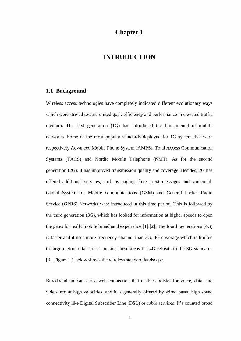
Wireless access technologies have completely indicated different evolutionary ways
which were strived toward united goal: efficiency and performance in elevated traffic
medium. The first generation (1G) has introduced the fundamental of mobile
networks. Some of the most popular standards deployed for 1G system that were
respectively Advanced Mobile Phone System (AMPS), Total Access Communication
Systems (TACS) and Nordic Mobile Telephone (NMT). As for the second
generation (2G), it has improved transmission quality and coverage. Besides, 2G has
offered additional services, such as paging, faxes, text messages and voicemail.
Global System for Mobile communications (GSM) and General Packet Radio
Service (GPRS) Networks were introduced in this time period. This is followed by
the third generation (3G), which has looked for information at higher speeds to open
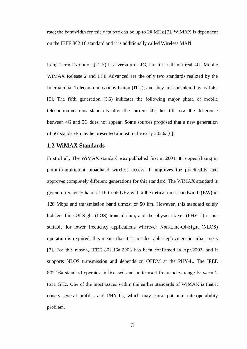
the gates for really mobile broadband experience [1] [2]. The fourth generations (4G)
is faster and it uses more frequency channel than 3G. 4G coverage which is limited
to large metropolitan areas, outside these areas the 4G retreats to the 3G standards
[3]. Figure 1.1 below shows the wireless standard landscape.
Broadband indicates to a web connection that enables bolster for voice, data, and
video info at high velocities, and it is generally offered by wired based high speed
connectivity like Digital Subscriber Line (DSL) or cable services. It’s counted broad

2
as a result of multiple types of services in which it can move across the extensive
domain, and mobile broadband combines these services to mobile devices [1] [4].
Figure 1.1: Wireless Standard Landscapes [4]
The IEEE 802.16, an answer to wide band wireless access, is called Worldwide
Interoperability for Microwave Access (WiMAX). It is one of the closest
technologies to meet the standards of real 4G, and it is also described as the first 4G
offering.
Before WiMAX, Local Area Network (LAN), Metropolitan Area Network (MAN)
and Wide Area Network (WAN) have been appeared to supply wireless
communications within various communication ranges. WiMAX is defined as
telecommunications technology which is geared toward providing wireless
connection over long distances up to 30 miles (50 km) for fixed stations, and 3 - 10
miles (5 - 15 km) for mobile stations. In WiMAX, when a user uses a 75 Mbps data
3
rate; the bandwidth for this data rate can be up to 20 MHz [3]. WiMAX is dependent
on the IEEE 802.16 standard and it is additionally called Wireless MAN.
Long Term Evolution (LTE) is a version of 4G, but it is still not real 4G. Mobile
WiMAX Release 2 and LTE Advanced are the only two standards realized by the
International Telecommunications Union (ITU), and they are considered as real 4G
[5]. The fifth generation (5G) indicates the following major phase of mobile
telecommunications standards after the current 4G, but till now the difference
between 4G and 5G does not appear. Some sources proposed that a new generation
of 5G standards may be presented almost in the early 2020s [6].
1.2 WiMAX Standards
First of all, The WiMAX standard was published first in 2001. It is specializing in
point-to-multipoint broadband wireless access. It improves the practicality and
approves completely different generations for this standard. The WiMAX standard is
given a frequency band of 10 to 66 GHz with a theoretical most bandwidth (BW) of
120 Mbps and transmission band utmost of 50 km. However, this standard solely
bolsters Line-Of-Sight (LOS) transmission, and the physical layer (PHY-L) is not
suitable for lower frequency applications wherever Non-Line-Of-Sight (NLOS)
operation is required; this means that it is not desirable deployment in urban areas
[7]. For this reason, IEEE 802.16a-2003 has been confirmed in Apr.2003, and it
supports NLOS transmission and depends on OFDM at the PHY-L. The IEEE
802.16a standard operates in licensed and unlicensed frequencies range between 2
to11 GHz. One of the most issues within the earlier standards of WiMAX is that it
covers several profiles and PHY-Ls, which may cause potential interoperability
problem.

4
The IEEE 802.16 standard has been approved in 2004 and the new version is known
as IEEE 802.16d “Fixed WiMAX”. The 802.16d-2004 standard doesn’t support
mobility. To resolve the problem of mobility, the IEEE 802.16e-2005 standard was
published and had full support for mobility. It is called “Mobile WiMAX” because it
is presented to support the mobility [8]. The mobile WiMAX air interface uses
Orthogonal Frequency Division Multiple Access (OFDMA), which is the most
popular varied access technique within the downlink (DL) and uplink (UL) to
improve multipath performance and BW development [1]. WiMAX Release 2 is a
second-generation with high-speed wireless communication technology released in
late 2012. It is an upgrade to the Mobile WiMAX. It offers faster UL and DL speeds
of up to 90 Mbps and 170 Mbps; it replaced the existing IEEE802.16e with
IEEE802.16m.
The basic characteristics of IEE802.16 standards are summarized below in Table 1.1.
Table 1.1: Summaries of IEEE802.16 Standards [7]
Parameter IEEE802.16 IEEE802.16d-2004 IEEE802.16e-2005
Frequency
Range
10Gz-66Gz 2Gz-11Gz 2Gz-11Gz for fixed;
2Gz-6Gz for Mobile
Channel
condition
“Fixed LOS” “Fixed NLOS” “Fixed and Mobile
NLOS”
Modulation QPSK;
16QAM;64QAM
QPSK;
16QAM;64QAM
QPSK;
16QAM;64QAM
Bit Rate 32-120Mbps 1-75Mbps 1-75Mbps
Channel
Bandwidths
20,25,28 MHz Scalable between
(1.25 to 20) MHz
Scalable between
(1.25 to 20 MHz)
Cell Radius 30 miles (3 to 5) miles (1 to 3)miles
Multiplexing TDM/TDMA TDM/TDMA/OFDMA TDM/TDMA/OFDMA

5
1.3 WiMAX vs. Wi-Fi
The comparison between WiMAX and Wi-Fi can be summarized according to the
following Table [4]:
Table 1.2: WiMAX vs. Wi-Fi
Parameter WiMAX Wi-Fi
IEEE Standards IEEE 802.l6 Standard IEEE 802.ll standard
Range Up to 40 miles
Or up to 211200 Feet
0.0189 miles
Or 100 feet
Bit Rate 75MbPs Up to 54Mbps
Scalability 1-1000 number of users 1-10 number of users
Channel Bandwidths flexible channel sizes from
l.5MHz to 20MHz
fixed channel sizes 20MHz
Frequency Range 2GHz to 11GHz Up to 5GHz
Quality of Service WiMAX can provide your
several levels of QoS
Wi-Fi doesn't guarantee any
QoS
Multiplexing TDM, TDMA, OFDMA CSMA
Duplexing TDD, FDD TDD
Modulation QPSK, 16 QAM, 64 QAM BPSK, QPSK, 16 QAM,
64 QAM
1.4 Motivation
In the course of present connectivity, a mobile station (MS) is equipped
with an IEEE 802.16 interface which is probably reaching to travel across multiple
base stations (BSs) so as to keep up the connection.
6
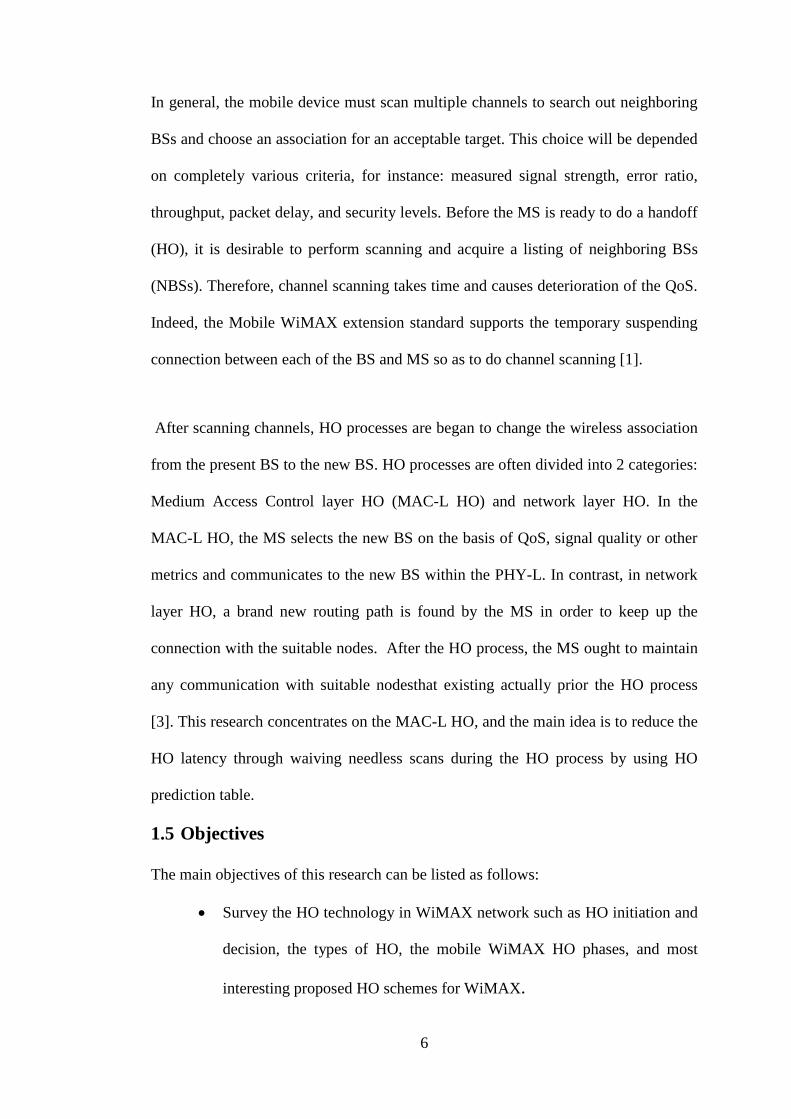
In general, the mobile device must scan multiple channels to search out neighboring
BSs and choose an association for an acceptable target. This choice will be depended
on completely various criteria, for instance: measured signal strength, error ratio,
throughput, packet delay, and security levels. Before the MS is ready to do a handoff
(HO), it is desirable to perform scanning and acquire a listing of neighboring BSs
(NBSs). Therefore, channel scanning takes time and causes deterioration of the QoS.
Indeed, the Mobile WiMAX extension standard supports the temporary suspending
connection between each of the BS and MS so as to do channel scanning [1].
After scanning channels, HO processes are began to change the wireless association
from the present BS to the new BS. HO processes are often divided into 2 categories:
Medium Access Control layer HO (MAC-L HO) and network layer HO. In the
MAC-L HO, the MS selects the new BS on the basis of QoS, signal quality or other
metrics and communicates to the new BS within the PHY-L. In contrast, in network
layer HO, a brand new routing path is found by the MS in order to keep up the
connection with the suitable nodes. After the HO process, the MS ought to maintain
any communication with suitable nodesthat existing actually prior the HO process
[3]. This research concentrates on the MAC-L HO, and the main idea is to reduce the
HO latency through waiving needless scans during the HO process by using HO
prediction table.
1.5 Objectives
The main objectives of this research can be listed as follows:
Survey the HO technology in WiMAX network such as HO initiation and
decision, the types of HO, the mobile WiMAX HO phases, and most
interesting proposed HO schemes for WiMAX.
7
Improve the performance of HO in WiMAX using load balancing and
reduce the HO latency, calculate dropping call probability, mean absolute
load difference, and average number of overhead SMS messages and
compare the proposed scheme with the WiMAX standard and other
proposed schemes.
1.6 Thesis Outline
The remainder of this thesis is organized as follows: In Chapter 2, literature review
of the features of WiMAX technology layers is presented; also the HO concepts for
the WiMAX networks are introduced. Moreover, the HO types and phases are
discussed, and the most interesting proposed schemes in WiMAX are also presented
in this chapter. The proposed scheme is presented in details in Chapter 3. Chapter 4
discusses our simulation results. Finally, the conclusion and the future work are
presented in Chapter 5.

8
Chapter 2
2 LITERATURE REVIEW
2.1 WiMAX Layers
The structure of Mobile WiMAX consists of five sub-profiles, namely, PHY, MAC,
duplexing mode, power classes, and radio profile as shown in Figure 2.1 below.
Although there are many various sets of channel BWs and center frequencies
absorbing various regional spectrum regulations, the same PHY and MAC features
are shared in mobile WiMAX products and also these products share same duplexing
mode. The PHY-L and MAC-L in the mobile WiMAX system profile are presented
in this section.
Figure 2.1: The Mobile WiMAX System Structure [1]
9
2.1.1 Physical Layers
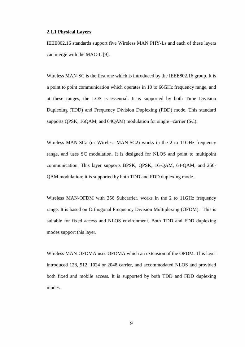
IEEE802.16 standards support five Wireless MAN PHY-Ls and each of these layers
can merge with the MAC-L [9].
Wireless MAN-SC is the first one which is introduced by the IEEE802.16 group. It is
a point to point communication which operates in 10 to 66GHz frequency range, and
at these ranges, the LOS is essential. It is supported by both Time Division
Duplexing (TDD) and Frequency Division Duplexing (FDD) mode. This standard
supports QPSK, 16QAM, and 64QAM) modulation for single –carrier (SC).
Wireless MAN-SCa (or Wireless MAN-SC2) works in the 2 to 11GHz frequency
range, and uses SC modulation. It is designed for NLOS and point to multipoint
communication. This layer supports BPSK, QPSK, 16-QAM, 64-QAM, and 256-
QAM modulation; it is supported by both TDD and FDD duplexing mode.
Wireless MAN-OFDM with 256 Subcarrier, works in the 2 to 11GHz frequency
range. It is based on Orthogonal Frequency Division Multiplexing (OFDM). This is
suitable for fixed access and NLOS environment. Both TDD and FDD duplexing
modes support this layer.
Wireless MAN-OFDMA uses OFDMA which an extension of the OFDM. This layer
introduced 128, 512, 1024 or 2048 carrier, and accommodated NLOS and provided
both fixed and mobile access. It is supported by both TDD and FDD duplexing
modes.

10
Wireless HUMAN, “High-speed Unlicensed MAN” is same as OFDM, but
frequency chosen is compulsory for permit ranges between 2 to 11GHz, and it is
supported by TDD duplexing mode.
2.1.1.1 Scalability of OFDMA
OFDMA creates the basis for Mobile WiMAX. It shows an outstanding performance
in NLOS multi-path channels with its relatively easy transceiver structures. It permits
efficient use of the available spectrum resources by time and frequency sub-
channelization. The easy transmission and reception structure of OFDMA allows
additionally possible implementation of advanced antenna techniques like Multi
Input Multi Output (MIMO) with acceptable complexity. Scalable OFDMA means
possibility to regulate the use of BWs and as such different environments through
varying spectral requirements will be served. The OFDMA is using 128- 512- 1024-
or 2048 bit “Fast Fourier Transform” (FFT) that enables to support scaling BWs
between 1.25 to 20 MHz. Table 2.1 show the OFDMA scalability parameters [10].
Table 2.1: OFDMA Scalability Parameters [10]

11
2.1.1.2 Adaptive modulation and coding (AMC)
The WiMAX PHY-L provides different modulation and coding schemes that offer
efficient and robust network access. The modulation schemes offered 64QAM,
16QAM, QPSK, and BPSK in sequence of increasing robustness and decreasing the
efficiency. The 64QAM provides the highest BW and requires good Signal to Noise
Ratio (SNR) while QPSK modulation requires less SNR than 64QAM, and it is the
most robust. There are also few coding rates which are used to support flexible
networking and used according to Carrier to Noise Ratio (CNR). The coding rates in
which it can be used are respectively 1/2, 3/4, 2/3 or 5/6. Figure 2.2 shows the above
mentioned modulation schemes [11].
Figure 2.2: Adaptive modulation schemes [10]
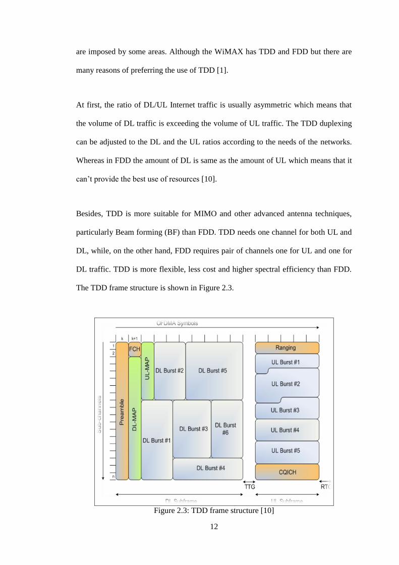
2.1.1.3 Time Division Duplexing (TDD) frame structure
Mobile WiMAX has only TDD as a duplexing mode, but recently WiMAX standards
add full and half FDD mode to be supported. This is because of local restrictions that
12
are imposed by some areas. Although the WiMAX has TDD and FDD but there are
many reasons of preferring the use of TDD [1].
At first, the ratio of DL/UL Internet traffic is usually asymmetric which means that
the volume of DL traffic is exceeding the volume of UL traffic. The TDD duplexing
can be adjusted to the DL and the UL ratios according to the needs of the networks.
Whereas in FDD the amount of DL is same as the amount of UL which means that it
can’t provide the best use of resources [10].
Besides, TDD is more suitable for MIMO and other advanced antenna techniques,
particularly Beam forming (BF) than FDD. TDD needs one channel for both UL and
DL, while, on the other hand, FDD requires pair of channels one for UL and one for
DL traffic. TDD is more flexible, less cost and higher spectral efficiency than FDD.
The TDD frame structure is shown in Figure 2.3.
Figure 2.3: TDD frame structure [10]

13
The TDD DL sub-frame commences with DL preamble which is utilized for PHY-L
approaches like synchronization, Carrier-to-Interference-and-Noise Ratio (CINR),
and Received Signal Strength Indication (RSSI) measurement. The Frame Control
Header (FCH) is following the DL preamble that contains frame information, like
MAP message size, usable subcarriers, and coding and modulation scheme. DL-
MAP and UL-MAP come after the FCH in the DL sub-frame. The MAP messages
contain the burst profile for every user. Because of the MAP which contains vital
information that is required to access to all users, it is sometime sent over an
extremely trustworthy link, for example, repetition coding & BPSK with rate 1/2
coding [1].
The UL sub-frame starts with ranging sub-channels that the MSs used it for
frequency and power adjustments, closed loop time, and for holding BW requests.
The UL bursts include user data transmission from MS to BS. The CQI channel is
used to transfer a channel quality information feedback [11].
2.1.1.4 The Data Rates of PHY Layer
Since the PHY-L of WiMAX is elastic, the difference of rate performance supports
the operating parameters. The modulation, coding scheme, and the utilized of
channel BW are the parameters which have a large effect on the PHY-L data rate.
Also other parameters, like oversampling rate, OFDM guard time, and number of sub
channels have effects as well. Table 2.2 below shows the PHY-L data rate at
different channel BWs [12].

14
Table 2.2: PHY-layer data rate at different channel bandwidths [1]
2.1.1.5 Hybrid Automatic Repeat Request (HARQ)
HARQ is a choice part in mobile WiMAX MAC; it is supported by only the
OFDMA PHY-L to provide a fast packet retransmission. Also, it works on this layer
when the sending packets are probably not received due to the reason of bit errors.
The cost of HARQ implementation is the negative side of it [11].
2.1.2 Mobile WiMAX MAC Layer
The main job of this layer is to support a connection between the upper layers and
PHY-L, and it has been designed and improved in order to enable PMP wireless
applications. The data is taken by the MAC-L from the higher layer which is known
as MAC Service Data Units (SDU) and arranges them into MAC Protocol Data Units
(PDU) for transmitting via the air. The reverse operation is done when the MAC-L
receives transmission. Figure 2.4 shows the several sub layers of MAC-L [13].

15
Figure 2.4: WiMAX Reference Models [7]
Fixed WiMAX and Mobile WiMAX MAC include a convergence sub-layer which
can be interacted with a group of upper layer protocols, like Ethernet, IP, ATM, and
the adoption of any future protocol (802.1Q).
The WiMAX MAC-L offers flexible allocation of capacity to different users and
uses a different PDU length to enable their efficient transfer. Varied PDUs of same
or different lengths can be collected into a single data burst to save PHY-L overhead;
also, several SDUs from the upper layer can be aggregated into one PDU in order to
save MAC overhead. Big PDUs can split into several small PDUs and sent via
various frames [14].

16
2.1.2.1 Channel Access Mechanisms
In Mobile WiMAX, the MAC-L at the BS is taking full responsibility for assigning
BW to MSs in the UL and the DL. The MS has some control over BW allocation
only when it contains several connections and sessions with the BS. In this regard,
the BW is allocated by the BS to the MS, and the decision is up to the MS to assign
the BW between several connections. Allocating BW to the MS must be done by the
BS according to meet the requirements of the incoming traffic, without intervention
of the MS, this is for the DL. Allocations must be on the basis of demands from the
MS; this is for the UL [4].
The WiMAX standard offers many of the techniques by which a MS can be asked
and get UL BW. The BS assigns shared or dedicated resources periodically to each
MS, with which it can be used to order BW, it is known as polling. Polling can be
achieved either in Unicast or in Multicast manner. The Multicast is achieved when
there is a lack in BW to poll each MS separately. When polling is completed in
multicast, the allocated slot for creating BW requests is a common slot, and every
polled MS tries to use it. Mobile WiMAX determines a resolution mechanism and
contention access, these issues occur when more than one MS tries to utilize the
common slot [1].
2.1.2.2 Quality of Service (QoS)
QoS Support is a basic section in the design of WiMAX MAC-layer. Strong QoS
management is realized through using a connection-oriented MAC architecture,
whenever all DL and UL connections are controlled by the SBS. WiMAX assigns a
principle of a service flow. A service flow is a one directional flow of packets with a
certain set of QoS parameters and is defined by a Service Flow Identifier (SFID)”. A

17
one direction logical link is built by the BS and the MS, it is known as a connection
between the two MAC-L peers. A Connection Identifier (CID) recognizes each
connection. This is done before any transmission occurs. Figure2.5 shows the
connection between MS and BS with service follows. The QoS parameters can
include maximum burst rate, maximum sustained traffic rate, minimum tolerable
rate, ARQ type,” tolerated jitter, traffic priority, maximum delay, service data unit
type and size, transmission PDU formation rules, a BW request mechanism to be
used, scheduling type, and others [4].
Figure 2.5: Mobile WiMAX QoS Support [1]
WiMAX specifies five scheduling types which must be bolstered by the BS MAC
scheduler for data transmission over a connection as shown in Table 2.3 below:

18
Table 2.3: Service Classes Supported in WiMAX [1]
1. UGS – the Unsolicited Grant Service: It is designed to support fixed - size UL data
packets at a Constant Bit Rate (CBR), this allows the use of real-time applications
like Voice over IP (VoIP).
2. RtPS - the Real-time Polling Service: This provides support for real-time UL
transmission with variable BW according to the size of data packets. This makes it
useful for video transmission.
3. NrtPS - Non-real-time polling service: It is designed to support delay - tolerant
data flows, which need variable-size data grants with an ensured rate, like an FTP.
The intervals between polls are variable and short enough to offer an adequate
service for the MS.

19
4. BE - Best Effort: This service type suits for Web browsing, and it does not need
minimum requirements for the connection. It allows users to use contention request
opportunities.
5. ErtPS - Extended real-time variable rate (ERT-VR) service: ERT-VR is an
association of UGS and rtPS. This service is not defined in Fixed WiMAX; it is
defined in Mobile WiMAX. It is designed to bolster real-time applications, like
voice, video, and VoIP.
2.1.2.3 Power Management
Mobile WiMAX has power saving advantages which permit MSs to work for long
periods without needing to recharging. Power saving is attained by shutting down
portions of the MS in a control way when there isn't active transmission and
reception [4].
Mobile WiMAX defines two modes of power efficient operation; these modes are
called “Sleep Mode and Idle Mode”. In the sleep mode, the MS turns off its devices
and becomes unavailable for predefined intervals; these periods are known by the
BS. The sleep mode offers flexibility for the MS; during the sleep mode, other BSs
can be scanned by the MS to gather information which helps for HO. This is also
minimizing the MS power consumption. Ide mode allows more power saving than
sleep mode, and it is optional in IEE802.16. Idle mode is a case in which the MS
completely shuts down and also without registering with any BS just available for
receiving DL broadcast traffic messaging. The MS does not have the ability to do
HO or register, and also the network and BS eliminate HO traffic from ineffectual
MS, these are the benefits of the Idle Modes [7].

20
2.1.2.4 Security Functions
WiMAX systems designed with flexible and robust security. It contains status of the
art methods to guarantee user data privacy and preventing unauthorized users.
Security is treated by a privacy sub-layer in the WiMAX MAC-L. There are many
aspects of WiMAX security [12]:
Support for privacy: The cryptographic schemes are used to encrypt the user
data; these schemes are proven robustness to ensure privacy. Both Triple
Data Encryption Standard (3DES) and Advanced Encryption Standard (AES)
are bolstered. Most of the system executions will probably utilize AES, as it
is the new encryption standard confirmed as compatible with (FIPS) Federal
Information Processing Standard and it is easy to perform it. The 256 bits or
128 bits basic is utilized for extracting the cipher that is creating in the
authentication stage.
Device/user authentication: IEEE802.16 provides an elastic ways for
authenticating MSs and users to avoid the use of unauthorized. The
authentication is depended on the “Internet Engineering Task Force” (IETF)
EAP that supports a variety of credentials, like username & password, smart
cards, and digital certificates. IEEE802.16 terminal devices come with built-
in X.509 digital certificates which have their MAC address and public key.
WiMAX operators can utilize username/password and use the certificates for
device authentication or smart card authentication for user authentication.
Flexible key-management protocol (Version-2): This protocol are utilized
for safely transmitting keying material from the BS to the MS, periodically re
permission and refreshing keys
21
Support for fast handoff: To support fast HO, WiMAX enables the MS to
use pre-authentication with a target BS (TBS) in order to assist accelerated
Re-entry.
2.1.2.5 Mobility Support
The Mobile WiMAX supports mobility management. In particular, the Mobile
WiMAX defines signaling techniques for MSs as they travel away from the coverage
area of one BS to another. The MS can apply a scanning process when it moves far
from the serving BS (SBS) to scan the wireless media for NBSs information that has
been gathered during scanning, like central frequencies of the NBSs and then it can
be sued in actual HO. The information about the parameters and central frequency of
the NBSs is periodically announced by the SBS [4]. The HO mechanisms in Mobile
WiMAX will be presented in details in the following section.
2.2 Handoff in Mobile WiMAX
In Mobile WiMAX, the HO or in some references called Handover is the process of
tearing down the existing connection with the current BS and setting up a new
connection with a NBS with better link quality. The transmitting of ongoing
communication channel could be in the frequency range, code word, or time slot to a
new BS.
At first, one of the basic requirements for HO to be possible is having at least 2 BSs,
the SBS and the TBS(s), and a MS which can connect to the two BSs. In some cases
the HO can occur in the same BS, but in different channels, this is called “Intra-cell
HO”. In contrast, the other is called “Inter-cell HO”. It is also possible for HO to
occur between different topologies for example (Wi-Fi to WiMAX); this is called
vertical HO while horizontal HO can occur within the same topology [10].

22
The main reasons for HO can be summarized as below:
Signal strength is dropped below and it is not enough to maintain the call
wherever the MS travels away from the BS.
All capacity of the BS is used up and there are more calls pending. The
channel is allocated to the call from the other BS in the range of overlapping
area to free-up capacity for other calls which can only connect with this BS.
When the MS behaviors changes.
To prevent the interference, when a channel is utilized by the MS, it becomes
interfered with other MS, and it uses same channel in another cell [15].
2.2.1 Handoff Initialization
HO initialization is referred to the decision of HO request. The RSS of the SBS
deteriorates when the MS travels away from it. Figure 2.6 elucidates the RSSs of
SBS1 and one NBS2. The strength of received signal becomes weaker when the MS
travels far from the BS1 and more powerful when it goes nearer to the BS2, because
it changes according to the distance [16].

23
Figure 2.6: HO Decision as a Function of HO Scheme [16]
A. Relative Signal Strength: At point A, in Figure 2.6 the HO is requested, but
the signal fluctuates. At this point, the HO is unnecessary, because several
HOs can be requested and the signal strength of the BS1 is still at a
satisfactory level. It is known as ping-pang effect.
B. Relative Signal Strength with Threshold: The HO occurs only when the
signal strength of BS1 is weaker than the signal strength of BS2. At point B,
the HO is unnecessary, because the threshold value (T1) is introduced in this
technique in order to overpower the ping-pang effect. The HO is started when
the RSS of BS1 is weaker than that of BS2 by the threshold amount.
C. Relative Signal Strength with Hysteresis: At point C, the HO is required
when the RSS from BS2 exceeds the RSS from BS1 with hypothesis value
(h). This value is used in order to initiate HO.

24
D. Relative Signal Strength with Hysteresis and Threshold: Both the threshold
and h margin are combined in this technique so as to decrease the number of
HOs. The HO occurs if the signal levels of BS1 falls below the threshold, and
the signal of BS2 is stronger than the first by h.
2.2.2 Handoff Decision
HO decision is dependent on RSS from SBS and NBSs. The HO initiation indicates
time that the HO is requested. 3 types of HO decision protocols are utilized in
different cellular systems [17].
A. Network Controlled Handoff (NCHO): This protocol is utilized in 1G
systems like, AMPS and NMT where the Mobile Telephone Switching Office
(MTSO) is responsible for the aggregate HO decision. In this protocol, the
needful RSS measurements of NBSs and HO decision are handled by the
network, which leads to high load in the network.
B. Mobile Assisted Handoff (MAHO): Conducting the RSS measurements and
then sending these measurements periodically to the BS is the responsibility
of the MS in this protocol. So, this protocol is used to decrease the load of the
network. The time of HO is decided by either the BS or Mobile Switching
Center depending on the RSS measurements. GSM uses this protocol.
C. Mobile Controlled Handoff (MCHO): This protocol expands the task of the
MS by awarding full control to it. The necessary measurements are made by
both MS and BS and these measurements are sent by the BS to the MS. Then
the time of HO is decided by the MS according to information obtained from
itself and the BS. WiMAX and Digital European Cordless Telephone (DECT)
use this protocol.

25
2.2.3 Handoff Types in WiMAX
There are two types of HO mechanisms: Hard HO (HHO) or “break before make”
and Soft HO “make before break”. In WiMAX, soft HO is splitted into two types:
Macro-Diversity HO (MDHO) and Fast Base Station Switching (FBSS). Shore HHO
is compulsory while the MDHO and FBSS are elective [10].
During HHO, the MS is connected with only one BS at a time. In HHO, the
connection of the MS with the old BS is released before it is connected with the new
one. This type of HO is utilized by the systems that utilize Time Division Multiple
Access (TDMA) and Frequency Division Multiple Access (FDMA), like GPRS and
GSM systems [17]. The HHO occurs when the signal strength from NBS is
exceeding the signal strength of the current BS as shown in Figure 2.7. Our work
highlights on the HHO.
Figure 2.7: Hard HO [10]
26
Unlike to the HHO, a soft HO can set up several connections with NBSs. It is
possible for the MS to communicate simultaneously with two BSs (the prior BS and
the new BS). This type of HO is utilized by the Code Division Multiple Access
(CDMA) systems where the cells utilize same frequency, but various code words.
Wideband CDMA (WCDMA) and Interim Standard 95 (IS-95) are an example for
the systems which use this type of HO.
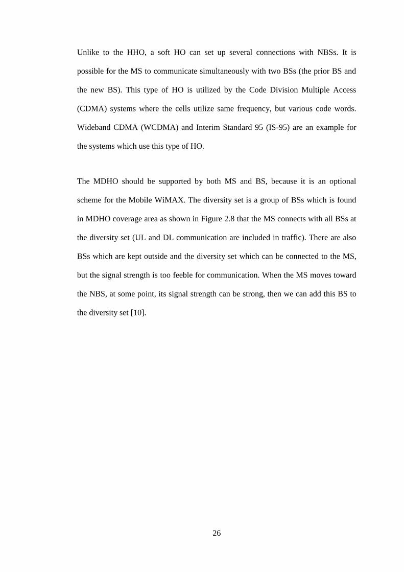
The MDHO should be supported by both MS and BS, because it is an optional
scheme for the Mobile WiMAX. The diversity set is a group of BSs which is found
in MDHO coverage area as shown in Figure 2.8 that the MS connects with all BSs at
the diversity set (UL and DL communication are included in traffic). There are also
BSs which are kept outside and the diversity set which can be connected to the MS,
but the signal strength is too feeble for communication. When the MS moves toward
the NBS, at some point, its signal strength can be strong, then we can add this BS to
the diversity set [10].

27
Figure 2.8: Macro Diversity HO [10]
The FBSS is similar to MDHO; it is also supported by both MS and BS, but the MS
solely connects with one BS in the diversity set with all UL and DL traffic, as shown
in Figure 2.9 below. This current SBS is called an anchor BS. All the BSs in the
diversity set receive the data directed to the MS, but just one of them sends the
packets across the air and the other BSs fall the received data. That means, each
frame can be sent via various BS in diversity set because the anchor BS can be
changed from frame to frame on the basis of the BS selection scheme [10].
28
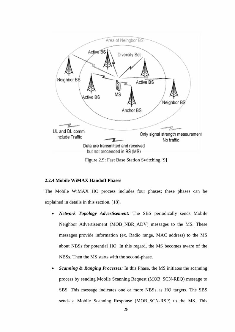
Figure 2.9: Fast Base Station Switching [9]
2.2.4 Mobile WiMAX Handoff Phases
The Mobile WiMAX HO process includes four phases; these phases can be
explained in details in this section. [18].
Network Topology Advertisement: The SBS periodically sends Mobile
Neighbor Advertisement (MOB_NBR_ADV) messages to the MS. These
messages provide information (ex. Radio range, MAC address) to the MS
about NBSs for potential HO. In this regard, the MS becomes aware of the
NBSs. Then the MS starts with the second-phase.
Scanning & Ranging Processes: In this Phase, the MS initiates the scanning
process by sending Mobile Scanning Request (MOB_SCN-REQ) message to
SBS. This message indicates one or more NBSs as HO targets. The SBS
sends a Mobile Scanning Response (MOB_SCN-RSP) to the MS. This
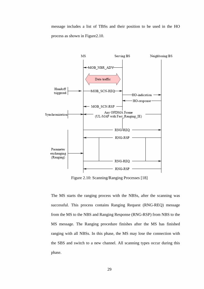
29
message includes a list of TBSs and their position to be used in the HO
process as shown in Figure2.10.
Figure 2.10: Scanning/Ranging Processes [18]
The MS starts the ranging process with the NBSs, after the scanning was
successful. This process contains Ranging Request (RNG-REQ) message
from the MS to the NBS and Ranging Response (RNG-RSP) from NBS to the
MS message. The Ranging procedure finishes after the MS has finished
ranging with all NBSs. In this phase, the MS may lose the connection with
the SBS and switch to a new channel. All scanning types occur during this
phase.

30
Handoff Decision and Initiation: This process can be taken by both the SBS
and the MS. MS HO Request message (MOB_MSHO-REQ) is used, if the
HO decision is taken from the MS. A BS HO Request message
(MOB_BSHO-REQ) is used, if the HO decision is adopted by the SBS. Here
we use MOB_MSHO-REQ as an example, (as shown in Figure 2.11).
Figure 2.11: HO decision and Initiation [18]
A HO starts when a (MOB_MSHO-REQ) message is sent by the MS to the
SBS pointing 1 or more probable BSs as a HO target. The SBS combines
information about NBSs and notifies the MS with MOB _HO-RSP messages.
The MS informs the SBS about its decision and begins the actual process of
HO by sending HO Indication message (MOB_HO-IND). This message may
31
also contain SBS release, HO cancel, or HO reject. Then the MS may begin
ranging after MOB_HO-IND message.
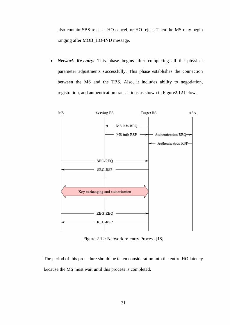
Network Re-entry: This phase begins after completing all the physical
parameter adjustments successfully. This phase establishes the connection
between the MS and the TBS. Also, it includes ability to negotiation,
registration, and authentication transactions as shown in Figure2.12 below.
”
Figure 2.12: Network re-entry Process [18]
The period of this procedure should be taken consideration into the entire HO latency
because the MS must wait until this process is completed.

32
2.3 Related Works
Several proposals have been suggested in the literature in order to reduce the HO
latency. In [19], the authors propose an algorithm using Arrival Time Difference
(ATD) and Carrier-to-Interference plus Noise Ratio (CINR) to estimate the TBS.
This scheme can reduce the HO latency by avoiding needless NBS scanning. But the
MS cannot recover full physical info of all neighbors BSs for choosing the final TBS.
In [20], (Fast DL MAP IE) message is presented in order to assist the MS receives
the DL traffic from the SBS during the HO process before synchronizing the UL
traffic with the TBS. The MS still uses the old Connection Identifier (CID) which has
not changed till the MS receives a new CID mandated by a TBS; it is potential that
the old CID is indeed utilized by other MS. However the throughput will be dropped
down because of collisions.
In [18], the network layer transmits some of the MAC-L control messages by
creating a layer 2tunnel between the SBS and the MS and a layer three tunnel
between the SBS and the TBS. And also this proposed cancels the network re-entry
latency, because the MS still connects with the SBS during the network re-entry
procedure.
In [21], the authors proposed a scheme called MDHOnew where they could decrease
the HO latency by selecting the best potential TBS according to QoS information on
the MS. When the MS receives a MOB_NBR-ADV message is containing
information about NBSs, it begins to build a list of NBSs which are arranged based
on the QoS parameter. However, this scheme can only be applied to the MDHO but
not to the HHO case.
33
In [22], the authors decreased the HO latency when the MS moves at a higher speed.
In order to achieve successful HO at high speed, they proposed an adaptive Forward
Error Correction (FEC) scheme that adaptively adjusts the number of unnecessary
bits according to the MS speed with retransmission.
In [23], the authors proposed an improved HO scheme for mobile WiMAX by
increasing the velocity factor of the MS, but they used beta (β) = 1, which means
path loss exponent has no effect on the received signal strength (RSS). The value of
β must vary based on the environment; because of this, the proposed scheme is not
realistic
In [3], the authors presented an efficient MAC-L HO scheme by utilizing mobility
patterns table; it is introduced to reduce the latency. The mobility table is supported
to assist the MS to expect the TBS and reduce the scanning time. The TBS is chosen
according to the BS that has highest HO times. Sometime the prediction of TBS is
incorrect when the mobility table is inexact or includes errors, and then the MS will
scan the incorrect BS.
In this thesis, we improved the scheme given in [3] by adding the load factor to the
mobility pattern table and renamed it as HO prediction table. The prediction table is
formed based on the standard scan results to be more accurate. The selection of the
TBS will be according to the minimum BS load, so that load balancing can be
achieved.
34
Chapter 3
3 THE PROPOSED HANDOFF SCHEME
In this chapter, we present the proposed scheme using Handoff prediction tables. The
main goal is to decrease HO delay time by canceling unnecessary scans during the
HO process. The HO prediction table is introduced at the BSs. It is used to assist the
MSs to predict the TBS. In the proposed scheme, the prediction table is formed on
the basis of the standard scan results, and its contents are updated after every
complete HO process on the basis of the HO decisions received from the MSs.
In the proposed scheme, the prediction table is retained by the SBS. It includes five
elements: previous BS’sID (PBS’s ID), target BS’sID (TBS’s ID), number of HO,
RSS, and the average load as shown in Table 3.1. The PBS is the BS with which the
MS was connected before its current connection. The TBS is the BS which the MS
will be connected with after the current BS. Number of HO means the number of HO
times which occurred on the BS. RSS represents strength of the TBS signal and the
load means the average load on the TBS.

35
Table 3.1: Example of the HO prediction table
Previous BS Target BS No. of HO RSS (db) Load
BS1 BS2 8.2 -65.5 0.50
BS1 BS3 9.55 -66.45 0.56
BS1 BS4 10.15 -65.9 0.55
BS1 BS5 10.35 -66.15 0.53
BS1 BS6 10 -65.4 0.546
BS1 BS7 9.7 -64 0.53
In Mobile WiMAX when the MS moves far from the SBS the signal strength will
decrease, then the MS comes in the scanning phase to search for the next BS to
connect with. The MS can obtain basic channel info of the NBSs because during the
MS transmission, it will receive MOB_ NBR –ADV messages from the SBS. When
the MS starts to scan for the TBS, firstly, it sends MOB _SCN-REQ to the present
SBS meaning that the MS will begin the scanning process. In this message, the MS
adds the nominee BSs list. This list is selected based on the physical channel info of
NBSs and just the NBSs that satisfy the needs of the MS are listed in it. And also this
message contains PBS ID and TBS ID. Figure 3.1 shows the proposed scheme
flowchart.

36
Figure 3.1: Flowchart of the Proposed HO Scheme

37
When the SBS receives the scan request message, it looks for the prediction table and
finds nominee BSs depending on PBS. If the ID of PBS in the scanning message is
like as the ID of PBS in the prediction table, then these BSs are treated as the
obtainable BS list for scanning, else the SBS will add these BSs to the HO prediction
table. To reduce the scanning time in the proposed scheme, the SBS arranges the
available BSs in the list according to their loads (with the minimum BS load being
first) in the HO predication table. Then the SBS sends this list to the MS in
MOB_SCN-RSP message.
After that, the MS stops connection with the SBS and begins the scanning procedure
based on the arranged BSs list. At first, the MS attempts to concurrency with the BS
which has minimum load and get more physical channel info about it. If the channel
case meets the MS requirements, the scan process is terminated. Else the MS should
scan the next BS.
When the MS chooses the TBS, it sends MOB_HO-IND message to the SBS. This
message contains the PBS ID and the TBS ID. Then the SBS updates the HO
prediction table according to this message. The SBS will transmit all of the DL data
packets of the MS to the new BS, because the MS is going to stop connection from
the SBS and all connections between the MS and the SBS will be terminated after
sending the MOB HO-IND message.

38
3.1 A Scenario to Demonstrate the Proposed Scheme
In this section, we give an example to demonstrate the proposed scheme. Figure 3.2
shows this example. There are 7 BSs, and the MS moves between these BSs. Since
the HO prediction table needs previous and current BSs, assume that BS1 is the
previous BS and BS7 is the current BS.
BS6
BS1
BS4
BS3
BS7
BS2
BS5
Figure 3.2: A Simple Scenario
When the MS travels far from BS7, the signal strength decreases, then the MS begins
the scanning phase to detect a new BS to connect with it. The MOB_NBR-ADV
message is listened by the MS to choose the nominee BSs list for example BS2 and
BS6.Then the MS sends a MOB_SCN-REQ message to the SBS (BS7) which
contains the candidate BSs list. When BS7 receives scanning request message, it
looks for the HO predication table and orders the candidate BSs list according to the
minimum BS load. Then the BS7 sends the list in the “MOB_SCN-RSP” message to
the MS. The BS2 has the minimum load as shown in Table.3.2. In this table we take
the average values of 20 runs. At first the MS starts to scan BS2, if it meets the MS

39
requirements, the MS selects it as a TBS and sends MOB_HO-IND message to the
BS7. The BS7 updates its HO predication table; therefore the load of the pair (BS1,
BS2) becomes 0.57, the RSS becomes -64db and the No. of HO become 13.7.
Table 3.2: The HO prediction table of BS7
Previous BS Target BS No. of HO RSS(db) Load
BS1 BS2 11.2 -65 0.5
BS1 BS3 11.25 -80.45 0.67
BS1 BS4 12.4 -77.9 0.65
BS1 BS5 13.6 -73.15 0.64
BS1 BS6 13.1 -65.15 0.66
One possible drawback of our scheme is that sometimes it may give an incorrect
decision, then the MS has to make second handoff to the correct BS.
In the next chapter we will show the performance analysis and simulation results and
how the proposed scheme improves the performance of the HO in WiMAX by
balancing the load of the BSs and reducing the scanning time.

40
Chapter 4
4 SIMULATION RESULTS
In this chapter, we present the performance analysis and the simulation results of the
proposed scheme, and we compare the results with WiMAX standard HO scheme.
We used MATLAB program in the simulation. In our HO scheme, the HO delay is
studied in Mobile WiMAX OFDMA/TDD model, and the frame duration is assumed
to be 5ms. And the SBS is the BS7 and (BS1, BS2 … BS6) are the NBSs, and the
number of MSs is deployed randomly among the BSs based on the capacity of the
BS, which means the maximum number of MSs in the BS is 30. Also, we assume
there is a road between SBS to reach to each NBS. Table 4.1 demonstrates the
simulation parameters [3]. The HO latency for WiMAX standard is ranging between
50-950 ms for all scanning types at different load ratios [3] [13] [18] [19]. In the
WiMAX standard each BS is scanned sequentially, and then the SBS negotiates with
the BS that provides the strongest signal to the MS. Whereas in the proposed scheme
only the BS that has minimum load is scanned. Figure 4.1 shows the comparison
between the scanning time required for WiMAX standard and the proposed scheme.

41
BS1 BS2 BS3 BS4 BS5 BS6
Target BS: BS2
(1) WiMAX Standard
BS2
Target BS:BS2
Total Scanning Time
Total Scanning Time
(2) Our Scheme
Figure 4.1: The required Scanning time for WiMAX Standard and Our proposed
42
Table 4.1: Input Parameters
Parameter Value
No. of Runs 40 runs
Maximum speed of MS 20m/s
Number of BSs 7
Capacity per BS 30
Overlap range 200m
Radio Range ( BS radius) 1 km
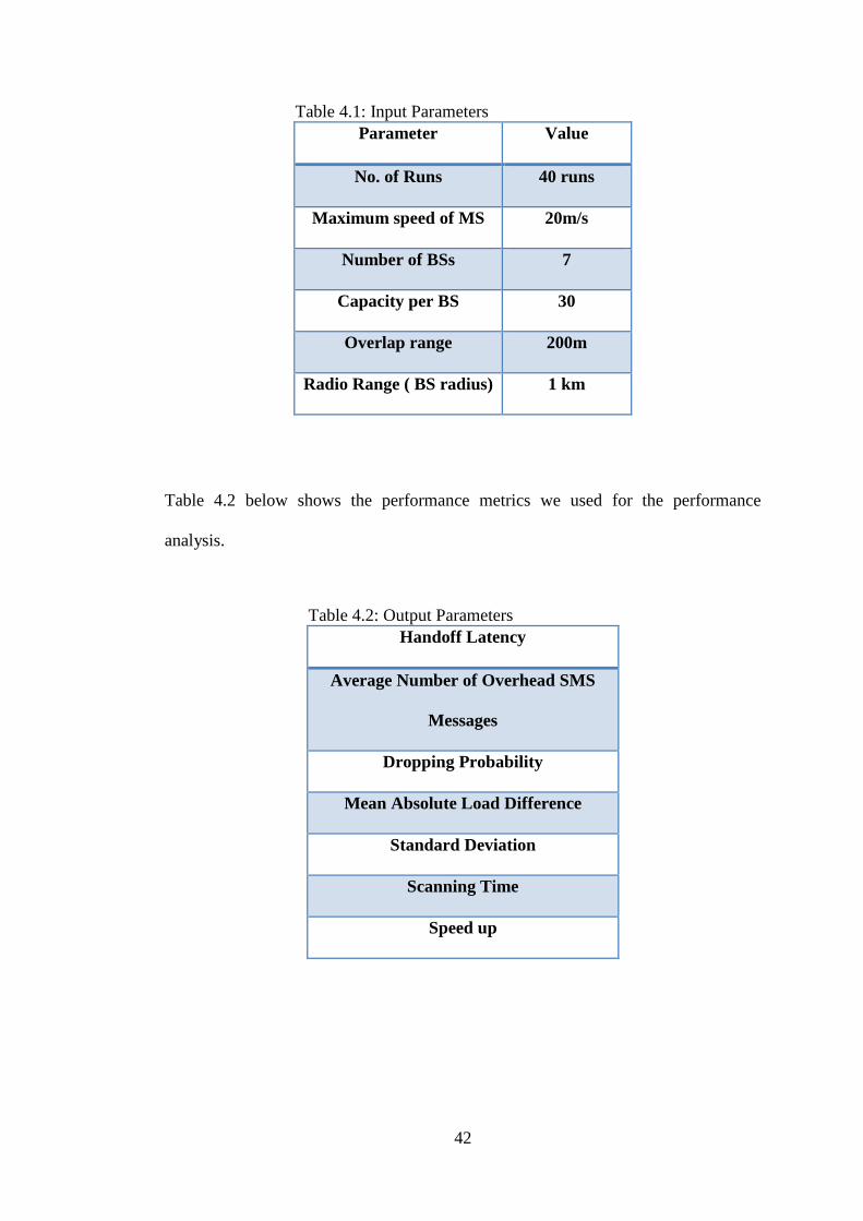
Table 4.2 below shows the performance metrics we used for the performance
analysis.
Table 4.2: Output Parameters
Handoff Latency
Average Number of Overhead SMS
Messages
Dropping Probability
Mean Absolute Load Difference
Standard Deviation
Scanning Time
Speed up

43
We can determine the Speed up factor as:
4.1 Handoff Latency
The handoff is affected by the latency which occurs during the scanning and ranging
process with NBSs. Also, in the network re-entry phase the TBS needs time to obtain
the authorization information for the MS ( ). After the authorization, is the
time required for registration. Four types of scanning processes are tested in order to
analysis the proposed scheme performance, these types are [3] [13]:
SCN Type_0: Scan NBSs without association. Just DL synchronization is required
for MS in order to obtain the physical channel info of the TBS. The scanning time
for SCN Type_0 can be calculated as:
Where is assumed to be 2 frames, which means 10ms, and n is the number of
NBSs that need to be scanned.
Figure 4.2 demonstrates the comparison between WiMAX standard and our HO
scheme.

44
Figure 4.2: Handoff latency using Type 0
This type of scan is the simplest one, because the scan time is not much affected by
load increasing. From the Figure 4.2 we see the proposed scheme performs better
than the standard WiMAX scheme in terms of HO latency. The achieved speed up
factor for this type of scanning is 1.67 at low load ratio and 1.4 at high load ratio.
SCN Type_1: Scan/association without coordination. The MS needs to finish the
contention-based ranging after the DL synchronization in order to exchange physical
information with the BS. The scanning time for SCN Type_1 can be calculated as:
(4.3)
45
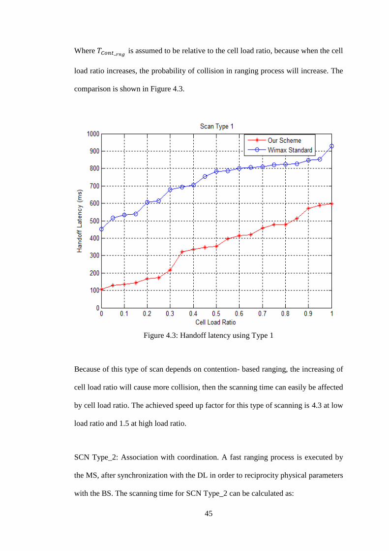
Where is assumed to be relative to the cell load ratio, because when the cell
load ratio increases, the probability of collision in ranging process will increase. The
comparison is shown in Figure 4.3.
Figure 4.3: Handoff latency using Type 1
Because of this type of scan depends on contention- based ranging, the increasing of
cell load ratio will cause more collision, then the scanning time can easily be affected
by cell load ratio. The achieved speed up factor for this type of scanning is 4.3 at low
load ratio and 1.5 at high load ratio.
SCN Type_2: Association with coordination. A fast ranging process is executed by
the MS, after synchronization with the DL in order to reciprocity physical parameters
with the BS. The scanning time for SCN Type_2 can be calculated as:

46
( ) (4.4)
Where is also assumed to be relative to the cell load ratio. The comparison is
shown in Figure 4.4.
Figure 4.4: Handoff latency using Type 2
The scan time of this type is also affected by the cell load ratio but less than the scan
time of type 1. The achieved speed up improvement of the proposed scheme over the
standard one for this type of scanning is 1.4 at low load ratio and 1.3 at high load
ratio.
SCN Type_3: Network assisted association reporting. The TBS doesn’t send ranging
response message directly to the MS but at first the TBS sent it to the SBS, then the

47
SBS sends RNG_RSP message to the MS in to MOB_ASC-REPORT message. The
scanning time for SCN Type_3 can be calculated as:
( ⌈ ⌉ ) (4.5)
The comparison is shown in Figure 4.5 below.
Figure 4.5: Handoff latency using Type 3
The time of this type of scan is also affected by the cell load ratio, but less than the
time of scan type 1 and scan type 2. The achieved speed up factor for this type of
scanning is 1.6 at low load ratio and 1.4 at high load ratio.
It is clear from the scanning types that the proposed scheme reduces the HO latency
in the comparison with the standard WiMAX scheme, because needless scans are
48
avoided using the HO prediction table. Also, the achieved speed up factor of our
scheme compared with the WiMAX standard scheme is ranging between 1.3 and 4.3
for all scanning types.
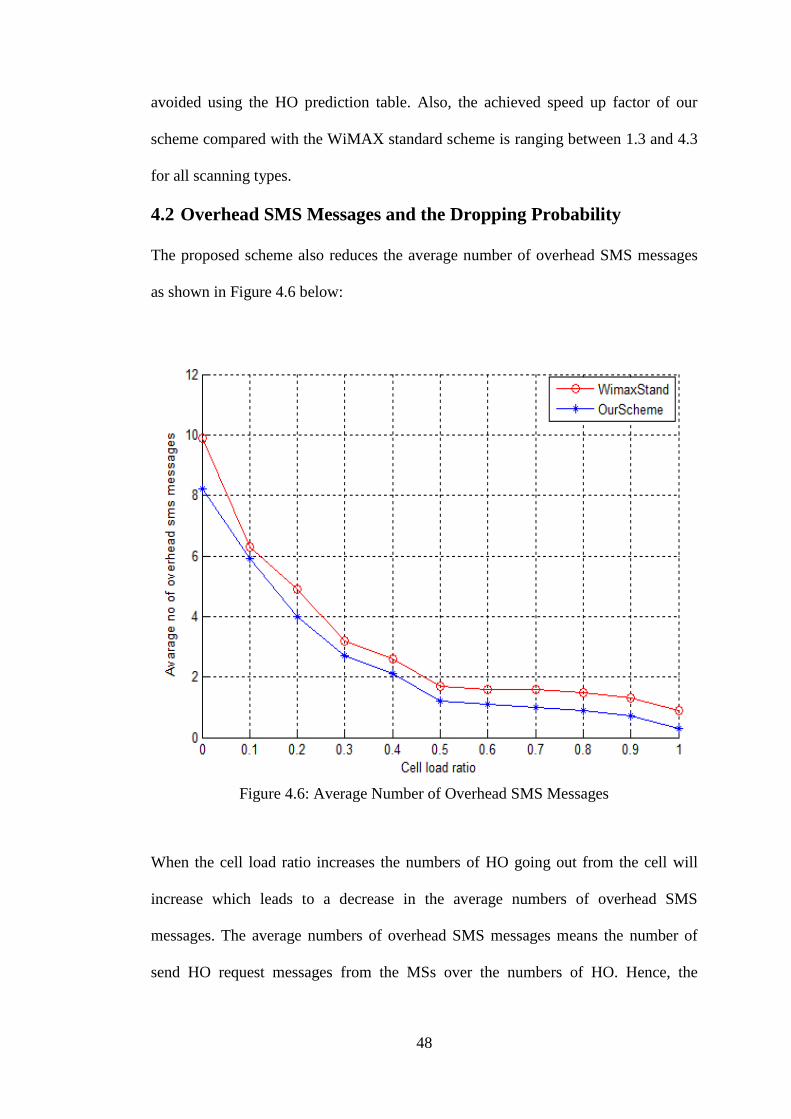
4.2 Overhead SMS Messages and the Dropping Probability
The proposed scheme also reduces the average number of overhead SMS messages
as shown in Figure 4.6 below:
Figure 4.6: Average Number of Overhead SMS Messages
When the cell load ratio increases the numbers of HO going out from the cell will
increase which leads to a decrease in the average numbers of overhead SMS
messages. The average numbers of overhead SMS messages means the number of
send HO request messages from the MSs over the numbers of HO. Hence, the

49
proposed scheme performs better than the standard WiMAX scheme with around
25% less overhead messages.
Figure 4.7: Dropping Probabilities
The call dropping probability results are shown in Figure 4.7. The proposed scheme
reduces the call dropping probability better than WiMAX standard. When the load
ratio increases, the dropping probability decreases because the number of HO going
out from the cell increases. The proposed scheme out performance the WiMAX
standard scheme by improving the calls dropping probability with around 23%.
4.3 Load Balancing
An important goal of the proposed scheme is balancing the load between BSs by
giving channels to the MS from the BSs that have minimum loads.

50
Figure 4.8: Mean Absolute Load Difference
As shown in figure 4.8, the average load on the BSs varies between 0.05 and 0.1,
which means just %5 difference.
Also the load standard deviation of the proposed scheme varies between 0.5 and 1,
which means only0.5 deference, as shown in Figure 4.9 below. Hence, load
balancing can be achieved with the proposed scheme.

51
Figure 4.9: Load Standard Deviations
4.4 Comparison with other Studies
To show the effectiveness of the proposed scheme, we did comparisons with other
recently proposed schemes. The comparison results with the MDHOnew scheme
proposed in [21]. In this scheme the authors selected the best possible BS which
supports service flow (QoS) at the MS. Although MDHO basically reduces the
latency, we find that our proposed scheme performs better than MDHOnew scheme
in the scanning process period. We take just one type of scanning to make the
comparisons (SCN Type_2). Also, the speed up factor for the scanning time can be
calculated as:

52
The comparison results are shown in Table 4.3 below:
Table 4.3: Time Comparison between Our Scheme and MDHOnew Scheme
Load Ratio MDHOnew[21] Our Scheme Speed up
0 55ms 35ms 1.6
0.5 80ms 60ms 1.3
The difference between the scanning times for each scheme is almost 20ms in the
low and high load. We achieved an acceptable speed up factor of the proposed
scheme over the MDHOnew scheme; it is 1.6 for low load ratio and 1.3 for high load
ratio.
Also, we make comparison to the HO latency for the proposed scheme with the
schemes proposed in [3] and [21]. The comparison results are shown in Table 4.4
below:
Table 4.4: Handoff Latency Comparison of Our Scheme with Other Schemes
Load
Ratio
MDHOnew
[21]
Scheme
of [3]
Our
Scheme
Speed up over
MDHOnew
Speed up over
Scheme of [3]
0 240ms 175 ms 166ms 1.45 1.05
0.5 260ms 245 ms 245ms 1.06 1
MDHOnew and Scheme of [3] are also taking the best possible TBS; MDHOnew
takes the TBS according to the QoS parameters which is supported at the MS.

53
Whereas the scheme of [3] selects the TBS which has highest handoff time from the
mobility pattern table. As it seen from the Table 4.4, the HO latency for the proposed
scheme at low load ratio is less than the MDHOnew latency by almost 75ms and less
than the latency of scheme of [3] by almost 9ms. In the 50% load ratio our proposed
scheme has less HO latency than the MDHOnew by 15ms and almost same as the
HO latency of Scheme of [3]. The achieved speed up of our scheme with MDHOnew
scheme is 1.45 at low load and 1.06 at high load. Also, compared with scheme of [3],
although our proposed scheme has same performance at high load, the achieved
speed up at low load is 1.05.
Also, we make comparisons with scheme of [3] for all scanning types at low and
high load ratios, and the results as in Table 4.5 and Table 4.6 below.
Table 4.5: Comparison of Our Scheme with Scheme of [3] when Cell Load Ratio (0)
Type of Scanning Scheme of [3] Our Scheme Speed up
Scan Type_0 150 130 1.15
Scan Type_1 220 105 2.1
Scan Type_2 175 166 1.05
Scan Type_3 165 163 1.01
Table 4.6: Comparison of Our Scheme with Scheme of [3] when Cell load Ratio(0.5)
Type of Scanning Scheme of [3] Our Scheme Speed up
Scan Type_0 170 151 1.2
Scan Type_1 380 350 1.08
Scan Type_2 245 245 1
Scan Type_3 200 195 1.02

54
We see our scheme performs better than the scheme of [3] in all scanning types at
high and low load ratios. Also, we achieved an acceptable speed up factor of the
proposed scheme over the scheme of [3] at low and high load ratios.
55
Chapter 5
5 CONCLUSION
WiMAX is a telecommunication technologies geared toward providing wireless
connection over long distances and large frequency band compare with other
technologies, but the distance is still limited and HO processes are needed to keep
wireless connections. So, preparing a fast HO in the WiMAX under the high velocity
state has become a difficult task. In HHO the MS spends hundreds of milliseconds
for scanning, ranging, authentication, and registration. During this time period, the
MS disconnected from the current BS, and hence its services are temporarily
stopped.
In this thesis, we improved the performance of the HO in WiMAX by balancing the
load and reducing the HO latency through using the HO prediction table. HO
prediction table are supported in order to assist the MS predicts the TBS and reduce
the scanning time.
The results show that the proposed scheme can significantly reduce the scanning
time by waiving unnecessary scans. It can reduce the average number of overhead
SMS messages by almost 25% and the dropping probability by almost 23%
comparing with the WiMAX standard scheme. Also, the proposed scheme can
balance the load of the BSs through giving channels to the MSs from the BSs which
have minimum load, then the load varies between BSs only 0.05 and the standard

56
deviation is between 0.5 to 1. When comparing the performance analysis of the
proposed scheme with other previously schemes, we showed that our proposed needs
less time than others for scanning. Hence the HO latency for the proposed scheme is
less than others in especially at high load ratio. The achieved speed up factor of our
scheme compared with the WiMAX standard scheme is ranging between 1.3 and 4.3
for all scanning types. Also, we achieved an acceptable speed up over other
interesting schemes proposed in literature.
The proposed scheme does not consider the type of traffic in the HO process. As a
future work the algorithm can be modified to consider multimedia traffic and give
some priority for real-time traffic in the HO process.

57
REFERENCES
[1] Y. Yu, "Handover performance in the mobile WiMAX," MS thesis, University
of South Florida, South Florida, USA, 2009.
[2] J. Nubarrón, "The Hub for Bright Minds," 2012 Bright Hub Inc, 1 12 2011.
[Online].Available:http://www.brighthub.com/mobile/emerging
platforms/articles/30965.aspx.
[3] Z. Zhang, R. W. Pazzi and A. Boukerche, "Reducing Handoff Latency for
WiMAX Networks using Mobility Patterns," in in Wireless Communications
and Networking Conference (WCNC), Sydney, Australia, 18-21 April. 2010.
[4] J. G. Andrews, A. Ghosh and R. Muhamed, Fundamentals of WiMAX:
Understanding Broadband Wireless Networking, Prentice Hall, 27, feb.2007.
[5] C. Janssen, "Wireless," Janalta Interactive Inc, 2014. [Online].
Available:http://www.techopedia.com/definition/2920/forth-generation
wireless-4g.
[6] "5G," [Online], 21 2 2014. _Available: http://en.wikipedia.org/wiki/5G.
[7] S. Omerovic, "WiMax Overview," MS thesis, University of Ljubljana, Slovenia.
58
[8] S. Khan, J. H. Lee and G. R. Khan, "Evaluation of Parameters for Improving
Handoff Performance in Mobile WiMAX Networks," International Journal of
Distributed and Parallel Systems (IJDPS), vol. 3, no. 5, pp. 85-89, September.
2012.
[9] R. Prasad and F. J. Velez, WiMAX Networks, Springer Science+ Business
Media B.V, 2010.
[10] A. Makelainen, "Analysis Handover Performance In Mobile WiMAX," MS
thesis, Hilisinky university, Espoo, 2007.
[11] V. Hytönen, "Handover performance in IEEE 802.16 mobile networks," MS
thesis, University of Jyväskylä, Jyväskylä, 2009.
[12] "Leaning_WiMAX,"_2014.[Online]._Available:
http://www.tutorialspoint.com/wimax.htm.
[13] M. Sanini, "Analysis of Handover Schemes in IEEE802.16(WiMAX)," MS
thesis, Thaper University, Patiala, 2008.
[14] I. Poole, " Wireless technologies," [Online]. Available: http://www.radio-
electronics.com/info/wireless/wimax/mac-layer.php.
[15] A. Mandal, "Mobile WiMAX: Pre-Handover Optamization Using Hybrid Base

59
Station Selection Procedure," MS thesis, Canterbury, 2008.
[16] W. Stallings, Wirless Communications and Networks, 2nd version, Pearson
Education, Inc, 22, november.2004.
[17] N. Ekiz, T. Salih, S. Küçüköner and K. Fidanboylu, "An Overview of Handoff
Techniques in Cellular Networks," International Journal of Information
Technology, vol. 2, pp. 132-136, 2005.
[18] L. Chen, X. Cai, R. Sofia and Z. Huang, "A Cross- Layer Fast Handover
Scheme For Mobile WiMAX," in Proc. of IEEE 66th VCT conference, pp.
1578-1582, Oct. 2007.
[19] D. H. Lee, K. Kyamakya and J. P. Umondi, "Fast handover algorithm for IEEE
802.16e broadband wireless access system," in IEEE Wireless Pervasive
Computing Conference, pp.16-18, January. 2006.
[20] S. Choi, G. H. Hwang, T. Kwon, A. R. Lim and D. H. Cho, "Fast Handover
Scheme for Real-Time Downlink Services in IEEE 802.16e BWA System,"
IEEE VTC, vol. 3, p. 2028–2032, Sweden, 2005.
[21] J. Ponchua and P. Chumchu, "A New Handover Mechanism for IEEE 802.16e,"
Journal of information science and technology, vol. 3, no. 2, pp. 7-13, 2012.

60
[22] Z. Yan, L. Huang and C. C. J. Kuo, "Seamless High-Velocity Handover Support
in Mobile WiMAX Networks," in 11th IEEE Singapore International
Conference, Guangzhou, pp.1680 - 1684, 19-21 Nov. 2008.
[23] P. Poolnisai and P. Chumchu, "Seamless Handover for High Velocity Mobile
Station in WiMAX," 13th International Symposium on Communications and
Information Technologies (ISCIT), pp. 35-40, Suart Thani,September.2013.
[24] "WiMAX-_Salient_Features,"_[Online]._Available:
http://www.tutorialspoint.com/wimax/wimax_salient_features.htm.
[25] P. S. Nandakumar, R. Singh and S. Singh, "Traffic Driven & Received Signal
Strength Adaptive Handoff Scheme," International Journal of Computer
Applications, vol. 21, p. 0975 – 8887, 2011.
[26] M. A. Hasan, "Performance Evaluation of WiMAX/IEEE 802.16 OFDM
Physical Layer," MS thesis, Helsinki University of Technology, Helsinki, 2007.

61
APPENDICES

62
Appendix A: Confidence Intervals
This test for Figure 4.6 When cell load ratio = 0.3
The Confidence interval =0.95
Y= Values
6 3 1.625 7.5 1.5
3 1.5 3 1.5 3
1.5 2.571 2.571 1.5 2.571
1.44 1.5 6 1.5 6
∑
Standard deviation ∑
√

63
(
)
(
)
……….
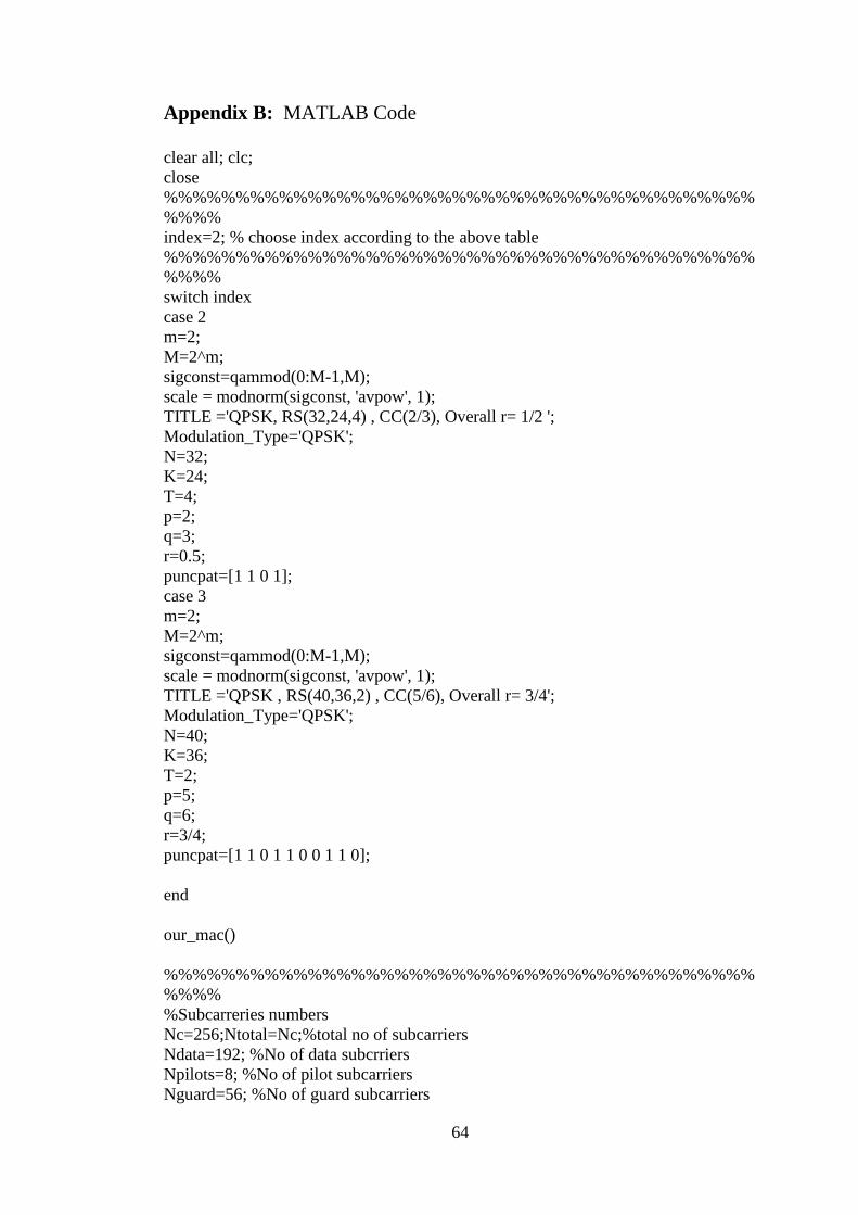
64
Appendix B: MATLAB Code
clear all; clc;
close
%%%%%%%%%%%%%%%%%%%%%%%%%%%%%%%%%%%%%%%%%
%%%%
index=2; % choose index according to the above table
%%%%%%%%%%%%%%%%%%%%%%%%%%%%%%%%%%%%%%%%%
%%%%
switch index
case 2
m=2;
M=2^m;
sigconst=qammod(0:M-1,M);
scale = modnorm(sigconst, 'avpow', 1);
TITLE ='QPSK, RS(32,24,4) , CC(2/3), Overall r= 1/2 ';
Modulation_Type='QPSK';
N=32;
K=24;
T=4;
p=2;
q=3;
r=0.5;
puncpat=[1 1 0 1];
case 3
m=2;
M=2^m;
sigconst=qammod(0:M-1,M);
scale = modnorm(sigconst, 'avpow', 1);
TITLE ='QPSK , RS(40,36,2) , CC(5/6), Overall r= 3/4';
Modulation_Type='QPSK';
N=40;
K=36;
T=2;
p=5;
q=6;
r=3/4;
puncpat=[1 1 0 1 1 0 0 1 1 0];
end
our_mac()
%%%%%%%%%%%%%%%%%%%%%%%%%%%%%%%%%%%%%%%%%
%%%%
%Subcarreries numbers
Nc=256;Ntotal=Nc;%total no of subcarriers
Ndata=192; %No of data subcrriers
Npilots=8; %No of pilot subcarriers
Nguard=56; %No of guard subcarriers

65
Nused=Ndata+Npilots;%No of used subcarriers
BW=5; %nominal channel bandwidth in MHz
%%%%%%%%%%%%%%%%%%%%%%%%%%%%%%%%%%%%%%%%%
%%oversampling rate NN=Fs/BW
if (rem(BW,1.75)==0)
NN=8/7;
else if (rem(BW,1.5)==0)
NN=86/75;
else if (rem(BW,1.25)==0);
NN=144/125;
else if (rem(BW,2.75)==0)
NN=316/275;
else if(rem(BW,2.0)==0)
NN=57/50;
else %otherwise
NN=8/7;
end
end
end
end
end
BW=BW*1e6; %nominal channel bandwidth in Hz
%%-----------------------------------------------------
% Derived OFDMA Symbol Parameters -
%%-----------------------------------------------------
Nfft=2^ceil(log2(Ndata)); % smallest power of 2 > Nused
Fs=floor((NN*BW)/8000)*8000;% sampling frequency in Hz
delta_f=Fs/Nfft;%subcarrier spacing in Hz
Tb=1/(delta_f);%useful symbol time in seconds
G=1/4; %cyclic prefix (G=Tg/Tb)
Tg=G*Tb; %CP time
Tsym=Tg+Tb; %totla symbol time
Ts=1/Fs; %sampling time in seconds
BWused=Nused*delta_f;%used bandwidth
Tframe=5e-3; %Frame period in s.
Ns=Tframe/Tsym; %Number of OFDMA symbols per frame.
%%%%%%%%%%%%%%%%%%%%%%%%%%%%%%%%%%%%%%%%%
%%%%
%Multipath CHANNEL Parameters of SUI-3 channel model for WiMAX
fd=0.5; %doppler frequency in Hz for WiMAX
%for mobile WiMAX fd must be calculated as follows
%c=3e8; % light speed in m/s
%fc=2; %carrier frequency in GHz
%V= 30 ; % mobile receiver velocity in km/h
%fd=fc*1e9*V*1e3/(3600)/c;%Doppler shift, in Hertz

66
P_db=[0 -11 -22]; %paths power in dB
tau=[0 0.4 0.9]*1e-6; %path delay vector in seconds
k=[3 0 0];%k-factor of Rice distribution in db
k=10.^(k/10);%k factor of Rice distribution in linear scale
chan = ricianchan(Ts,fd,k,tau,P_db); %construct the channelobject object
chan.DopplerSpectrum=doppler.rounded; %define the doppler fillter frequency
spectrum
chan.StoreHistory=0;chan.ResetBeforeFiltering=1;%to reset before every filtering
chan.NormalizePathGains=1; %to normalize path gain
D=chan.ChannelFilterDelay; %delay of the channel object
%%%%%%%%%%%%%%%%%%%%%%%%%%%%%%%%%%%%%%%%%