Embed Size (px)
Citation preview
1
An educational tool to assist the design process of switched reluctance
machines
ABSTRACT
The design of electric machines is a hot topic in the syllabuses of several undergraduate and
graduate courses. With the development of hybrid and electrical vehicles, this subject is gaining
more popularity, especially in electrical engineering courses. This paper presents a computer-
aided educational tool to guide engineering students in the design process of a switched
reluctance machine (SRM). A step-by-step design procedure is detailed and a user guide
interface (GUI) programmed in the Matlab® environment developed for this purpose is shown.
This GUI has been proved a useful tool to help the students to validate the results obtained in
their lecture assignments, while aiding to achieve a better understanding of the design process of
electric machines. A validation of the educational tool is done by means of finite element
method (FEM) simulations.
Keywords Computer-aided design, electrical engineering, sizing equations, switched reluctance
motor.
INDEX OF SYMBOLS
A Area [mm2]
As Electric loading [A/m] B Flux density [T] bsy, bry Width of stator/rotor yoke
sp, rp, Stator/rotor polar angle
2
D Diameter [mm]
FS Frame size
Φ Magnetic flux [Wb]
ψ Flux linkage [Wb]
g Air gap length [mm]
hsp, hrp, hc Height of stator/rotor pole or coil [mm]
i Current [A]
J Current density [A/mm2]
ke, kd Efficiency, duty cycle
l Axial length [mm]
L Inductance [H]
n Speed [r/min]
Ns, Nr Number of stator/rotor poles
T Torque [N·m]
P Power [W]
q Number of phases
Reluctance
Tph Turns per phase
V Voltage [V]
ω Angular speed [rad/s]
ωsp, ωrp, ωc Width of stator/rotor pole or coil
INTRODUCTION
Hybrid and electric vehicles have several advantages over ICE (internal combustion engine)
powered vehicles such as higher efficiency or lower exhaust emissions [1]. Although several
types of electric machines exist, SRMs offer appealing features including simple and rugged
construction, brushless design, high temperature capability, or fault-tolerant operation among
others [2,3]. They are even envisaged for electric vehicle (EV) in-wheel applications [4]. It is
also known that SRMs have higher specific torque and efficiency than equivalent induction
machines. SRMs have two main drawbacks, i.e. an important and an inherent difficulty in the
control due to their inherent non-linear behavior since they operate under saturation conditions,
and higher torque ripple than other electric machines. Consequently, SRMs are less applied in
industrial environments and therefore much less studied in most electrical engineering courses
than other types of electric machines [5]. However, SRMs are good candidates in applications
which do not prioritize a very low torque ripple or a fine positioning, such as in electric vehicle

3
drivetrains [1].
This work is aimed to foster students’ interest and motivation in the design of electric machines
topic. The learning system presented in this paper involves both machine sizing by means of an
iterative system based on analytical equations and the design verification through a computer-
aided educational tool. This tool allows the students to validate the design method and
calculations proposed in the lecture sessions. Computer-aided educational tools are appealing
since they can improve the quality of education, especially in engineering courses. They can
also be a good complement of lecture and practical sessions. It is also recognized that these tools
can facilitate students learning, since they provide graphical interaction and flexibility, thus
some difficult topics become more visual [6,7]. In addition some computer-aided tools allow
testing and validating machines and drives in a virtual way, thus minimizing costs and
difficulties of experimental tests.
The GUI presented in this paper provides a graphical, friendly and efficient environment that
facilitates the design process of SRMs. The GUI allows introducing the main design parameters
and restrictions of the SRM to be designed, such as the desired output power, rated speed, rated
phase current, number of phases, configuration or materials among others, and calculates the
dimensions and the main mechanical, electric and magnetic parameters which describe the
behavior of the designed SRM.
It is worth noting that although there are several educational papers dealing with the topic of
performance analysis and control of different types of electric machines [5,7,8], the authors of
this work have found no educational papers dealing with the topic of designing and sizing
SRMs.
4
COURSE STRUCTURE AND DETAILS
The computer assisted design of the SRM described in this paper is taught in the Plug-In Hybrid
Electric Vehicles: Concept, design and project of Electric propulsion systems, a 10-weeks
elective course of the eighth-semester Degree in Engineering taught at the ETSEIAT school of
the Universitat Politècnica de Catalunya (UPC). This course has an estimated students’ load of 3
ECTS (European Credit Transfer and Accumulation System). The lectures meet for two one-
hour lecture sessions every week, and every two weeks students attend a two-hour practical
session in which the computer assisted motor design experiment is taught. The contents of the
Plug-In Hybrid Electric Vehicles: Concept, design and project of Electric propulsion systems
course are as follows:
Hybrid electric vehicles
Electric propulsions systems for vehicles
Electric drive train design
Design of a control drive system
Analysis of integration of plug-in hybrid electric vehicles in the distribution grid
THE SIZING PROCEDURE
Electric machines are often initially designed and sized by applying the output equation, which
relates the main machine parameters such as length, bore diameter, base speed, electric loading
and magnetic flux density to the rated output power [9]. From this equation an estimation of the
main dimensions can be obtained, which are the starting point in the design evaluation process.
The sizing equation of the SRM can be written as,
min/,
22
··)···()/1(·120·· rSRMs
k
audeout nlDABLLkkP
L
(1)
5
ke being the efficiency, kd the duty cycle, La and Lu being, respectively, the aligned and
unaligned inductances, B the stator pole flux density at the aligned position, As the electric
loading, D the bore or stator inner diameter, l the axial length of the motor and nSRM is the rated
or base speed expressed in r/min. Note that (1) supposes constant peak values of phase currents
and voltages.
However, to directly size the SRM from (1), some assumptions need to be established, such as
the values of ke, kd, kL, B and As. The accuracy of the final solution will greatly depend on the
degree of uncertainty of these assumptions. Therefore, a more accurate sizing procedure than the
direct application of (1) is carried out in this work. Since the SRM is often used as a variable-
speed actuator, both the rated output power and the base speed are usually design specifications.
Therefore the output torque can be obtained from,
min/,
·30
rSRM
out
SRM
outout
n
PPT
(2)
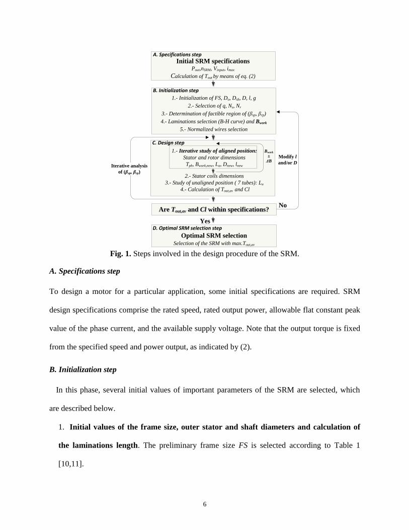
Fig. 1 summarizes the procedure applied to design the SRM, which is described in this section.
6
D. Optimal SRM selection step
C. Design step
A. Specifications step
B. Initialization step
Initial SRM specifications Pout,nSRM, Vinput, imax
Calculation of Tout by means of eq. (2)
1.- Initialization of FS, Do, Dsh, D, l, g
2.- Selection of q, Ns, Nr
3.- Determination of factible region of (βsp, βrp)
4.- Laminations selection (B-H curve) and Bwork
5.- Normalized wires selection
1.- Iterative study of aligned position:
Stator and rotor dimensions
Tph, Bwork,new, La, Dnew, lnew
2.- Stator coils dimensions
3.- Study of unaligned position ( 7 tubes): Lu
4.- Calculation of Tout,av and Cl
Optimal SRM selection
Iterative analysis
of (βsp, βrp)
Selection of the SRM with max.Tout,av
Are Tout,av and Cl within specifications?Are Tout,av and Cl within specifications?
Yes
Modify l
and/or D
No
Bwork ± ΔB
Fig. 1. Steps involved in the design procedure of the SRM.
A. Specifications step
To design a motor for a particular application, some initial specifications are required. SRM
design specifications comprise the rated speed, rated output power, allowable flat constant peak
value of the phase current, and the available supply voltage. Note that the output torque is fixed
from the specified speed and power output, as indicated by (2).
B. Initialization step
In this phase, several initial values of important parameters of the SRM are selected, which
are described below.
1. Initial values of the frame size, outer stator and shaft diameters and calculation of
the laminations length. The preliminary frame size FS is selected according to Table 1
[10,11].
7
Table 1. Frame Size Selection for 1500 r/min Motors
Rated speed
ω (r/min)
Output power
Pout (kW)
Frame size
FS (mm) 1500 0.12 63
1500 0.18 63
1500 0.25 71
1500 0.37 71
1500 0.55 80
1500 0.75 80
1500 1.10 90
1500 1.50 90
1500 2.20 100
1500 3.00 100
1500 4.00 112
1500 5.50 132
1500 7.50 132
1500 11.0 160
1500 15.0 160
1500 18.5 180
1500 22.0 180
1500 30.0 200
1500 37.0 225
1500 45.0 225
1500 55.0 250
1500 75.0 280
1500 90.0 280
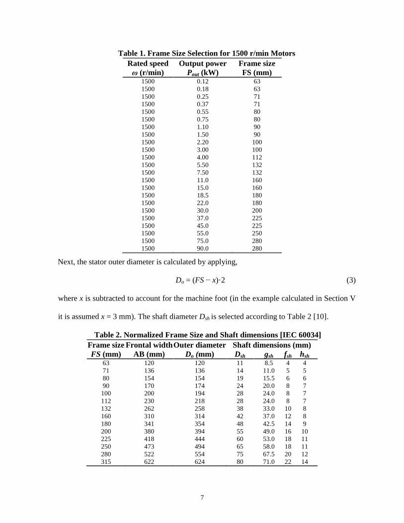
Next, the stator outer diameter is calculated by applying,
Do = (FS − x)·2 (3)
where x is subtracted to account for the machine foot (in the example calculated in Section V
it is assumed x = 3 mm). The shaft diameter Dsh is selected according to Table 2 [10].
Table 2. Normalized Frame Size and Shaft dimensions [IEC 60034]
Frame size Frontal width Outer diameter Shaft dimensions (mm)
FS (mm) AB (mm) Do (mm) Dsh gsh fsh hsh 63 120 120 11 8.5 4 4
71 136 136 14 11.0 5 5
80 154 154 19 15.5 6 6
90 170 174 24 20.0 8 7
100 200 194 28 24.0 8 7
112 230 218 28 24.0 8 7
132 262 258 38 33.0 10 8
160 310 314 42 37.0 12 8
180 341 354 48 42.5 14 9
200 380 394 55 49.0 16 10
225 418 444 60 53.0 18 11
250 473 494 65 58.0 18 11
280 522 554 75 67.5 20 12
315 622 624 80 71.0 22 14
8
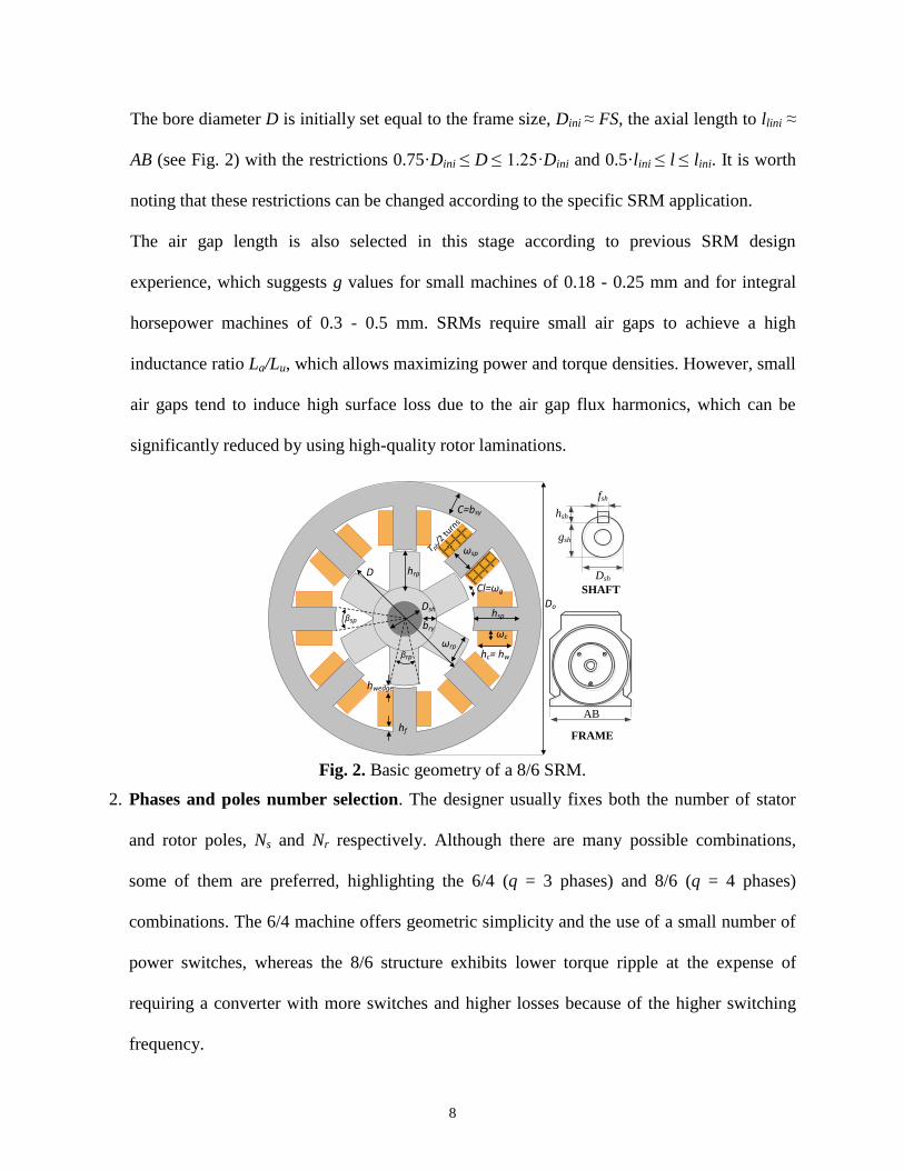
The bore diameter D is initially set equal to the frame size, Dini ≈ FS, the axial length to llini ≈
AB (see Fig. 2) with the restrictions 0.75·Dini ≤ D ≤ 1.25·Dini and 0.5·lini ≤ l ≤ lini. It is worth
noting that these restrictions can be changed according to the specific SRM application.
The air gap length is also selected in this stage according to previous SRM design
experience, which suggests g values for small machines of 0.18 - 0.25 mm and for integral
horsepower machines of 0.3 - 0.5 mm. SRMs require small air gaps to achieve a high
inductance ratio La/Lu, which allows maximizing power and torque densities. However, small
air gaps tend to induce high surface loss due to the air gap flux harmonics, which can be
significantly reduced by using high-quality rotor laminations.
hc= hw
Dsh
D
ωc
ωsp
hsp
C=bsy
bry
Do
Cl=ωg
hrp
T ph/2
turn
s
βsp
βrp
ωrp
hfFRAME
SHAFT
AB
Dsh
fsh
gsh
hsh
hwedge
Fig. 2. Basic geometry of a 8/6 SRM.
2. Phases and poles number selection. The designer usually fixes both the number of stator
and rotor poles, Ns and Nr respectively. Although there are many possible combinations,
some of them are preferred, highlighting the 6/4 (q = 3 phases) and 8/6 (q = 4 phases)
combinations. The 6/4 machine offers geometric simplicity and the use of a small number of
power switches, whereas the 8/6 structure exhibits lower torque ripple at the expense of
requiring a converter with more switches and higher losses because of the higher switching
frequency.
9
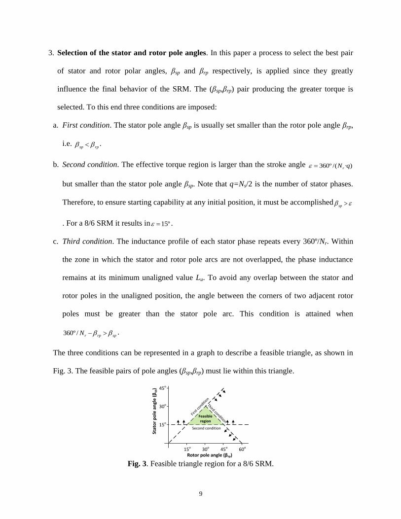
3. Selection of the stator and rotor pole angles. In this paper a process to select the best pair
of stator and rotor polar angles, βsp and βrp respectively, is applied since they greatly
influence the final behavior of the SRM. The (βsp,βrp) pair producing the greater torque is
selected. To this end three conditions are imposed:
a. First condition. The stator pole angle βsp is usually set smaller than the rotor pole angle βrp,
i.e. rpsp .
b. Second condition. The effective torque region is larger than the stroke angle )·(/º360 qNr
but smaller than the stator pole angle βsp. Note that q=Ns/2 is the number of stator phases.
Therefore, to ensure starting capability at any initial position, it must be accomplished sp
. For a 8/6 SRM it results in º15 .
c. Third condition. The inductance profile of each stator phase repeats every 360º/Nr. Within
the zone in which the stator and rotor pole arcs are not overlapped, the phase inductance
remains at its minimum unaligned value Lu. To avoid any overlap between the stator and
rotor poles in the unaligned position, the angle between the corners of two adjacent rotor
poles must be greater than the stator pole arc. This condition is attained when
sprprN /º360 .
The three conditions can be represented in a graph to describe a feasible triangle, as shown in
Fig. 3. The feasible pairs of pole angles (βsp,βrp) must lie within this triangle.
15o
15o
30o
30o
45o
45o
60o
Feasible region
Rotor pole angle (βrp)
Stat
or
po
le a
ngl
e (β
sp)
First
conditi
on
Second condition
Third condition
Fig. 3. Feasible triangle region for a 8/6 SRM.
10
The feasible region restricts the possible combinations of stator and rotor pole angles but
does not provide the better solution. It is possible to search for the combination (βsp,βrp) that
produces the maximum torque following the procedure described in section III.C [12], which
is obtained from the full design of the SRM. Therefore, successive iterations must be
performed to obtain the optimum value of the (βsp,βrp) pole angles.
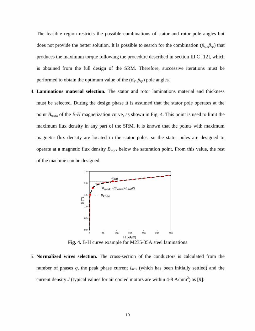
4. Laminations material selection. The stator and rotor laminations material and thickness
must be selected. During the design phase it is assumed that the stator pole operates at the
point Bwork of the B-H magnetization curve, as shown in Fig. 4. This point is used to limit the
maximum flux density in any part of the SRM. It is known that the points with maximum
magnetic flux density are located in the stator poles, so the stator poles are designed to
operate at a magnetic flux density Bwork below the saturation point. From this value, the rest
of the machine can be designed.
H (kA/m)
0 50 100 150 200 250 300
B (
T)
0.0
0.5
1.0
1.5
2.0
2.5
Bsat
Bknee
Bwork =(Bknee+Bsat)/2
Fig. 4. B-H curve example for M235-35A steel laminations
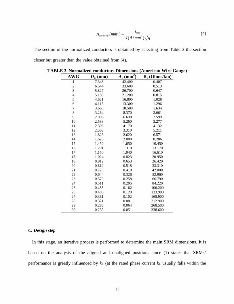
5. Normalized wires selection. The cross-section of the conductors is calculated from the
number of phases q, the peak phase current imax (which has been initially settled) and the
current density J (typical values for air cooled motors are within 4-8 A/mm2) as [9]:
11
qmmAJ
immA màx
conductor)·/(
)(2
2 (4)
The section of the normalized conductors is obtained by selecting from Table 3 the section
closer but greater than the value obtained from (4).
TABLE 3. Normalized conductors Dimensions (American Wire Gauge)
AWG Dw (mm) Ac (mm2) Rs (Ohms/km)
1 7.348 42.400 0.407
2 6.544 33.600 0.513
3 5.827 26.700 0.647
4 5.189 21.200 0.815
5 4.621 16.800 1.028
6 4.115 13.300 1.296
7 3.665 10.500 1.634
8 3.264 8.370 2.061
9 2.906 6.630 2.599
10 2.588 5.260 3.277
11 2.305 4.170 4.132
12 2.503 3.310 5.211
13 1.828 2.620 6.571
14 1.628 2.080 8.286
15 1.450 1.650 10.450
16 1.291 1.310 13.170
17 1.150 1.040 16.610
18 1.024 0.823 20.950
19 0.912 0.653 26.420
20 0.812 0.518 33.310
21 0.723 0.410 42.000
22 0.644 0.326 52.960
23 0.573 0.258 66.790
24 0.511 0.205 84.220
25 0.455 0.162 106.200
26 0.405 0.129 133.900
27 0.361 0.102 168.900
28 0.321 0.081 212.900
29 0.286 0.064 268.500
30 0.255 0.051 338.600
C. Design step
In this stage, an iterative process is performed to determine the main SRM dimensions. It is
based on the analysis of the aligned and unaligned positions since (1) states that SRMs’
performance is greatly influenced by kL (at the rated phase current kL usually falls within the

12
range 0.65 < kL < 0.75) which depends on the ratio between the aligned and unaligned
inductances. Therefore, the sizing process of the SRM requires an accurate calculation of both
inductances. To this end, in this section the values of both Lu and La inductances are calculated
by means of reluctance models, although it is known that this method provides an inherent error,
especially due to the calculation of the unaligned inductance [9].
1. Iterative study of the aligned position. The aligned position is reached when the symmetry
axes of the stator and rotor poles coincide. The analytical calculation of the flux linkages for
the aligned position neglects the leakage flux. Initially, a prospective flux density Bwork in the
stator poles is assumed. From it, the flux densities of different sections of the SRM are
calculated by applying flux continuity conditions, assuming that the areas of the cross
sections (air gap, stator and rotor poles and yokes) are known.
Now the stator dimensions can be calculated on the basis of maximum magnetic flux
density in the stator. A good practice consists in limiting the flux density of the stator yoke
around half the value in the stator poles, that is, Bs,y = 0.5·Bwork [9]. The width ωsp of the
stator poles is selected to accommodate the pole flux density, so
sp = D·βsp/2 (5)
Since the flux density in the stator core is limited to one-half of the flux density in the stator
poles, the stator yoke width results in,
bsy≈ sp (6)
Next, the height of the stator poles is calculated from Fig. 2 as,
2
·20 DbDh
sy
sp
(7)
Now, the rotor dimensions are selected. In [9] it is suggested to limit the flux density of the
rotor yoke around 80% of that in the stator poles, thus Bry = 0.8·Bmax. Based on the flux
13
density condition above, the rotor yoke width results in,
6.1/spryb (8)
Finally, from the geometry shown in Fig. 1, the rotor pole height is calculated as,
2
22 rysh
rp
b·Dg·Dh
(9)
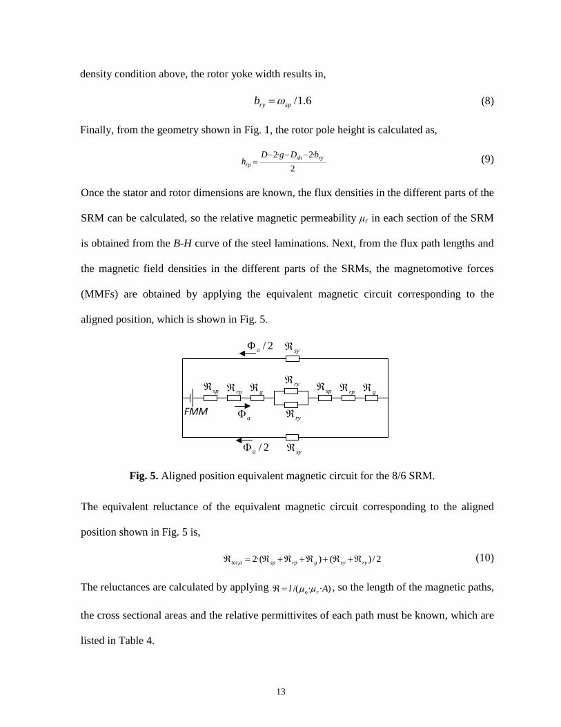
Once the stator and rotor dimensions are known, the flux densities in the different parts of the
SRM can be calculated, so the relative magnetic permeability μr in each section of the SRM
is obtained from the B-H curve of the steel laminations. Next, from the flux path lengths and
the magnetic field densities in the different parts of the SRMs, the magnetomotive forces
(MMFs) are obtained by applying the equivalent magnetic circuit corresponding to the
aligned position, which is shown in Fig. 5.
sprp g sp
rp g
sy
sy
ry
ry
FMMa
2/a
2/a
Fig. 5. Aligned position equivalent magnetic circuit for the 8/6 SRM.
The equivalent reluctance of the equivalent magnetic circuit corresponding to the aligned
position shown in Fig. 5 is,
2/)()·(2, rysygrpspatot (10)
The reluctances are calculated by applying )··/( Al ro , so the length of the magnetic paths,
the cross sectional areas and the relative permittivites of each path must be known, which are
listed in Table 4.
14
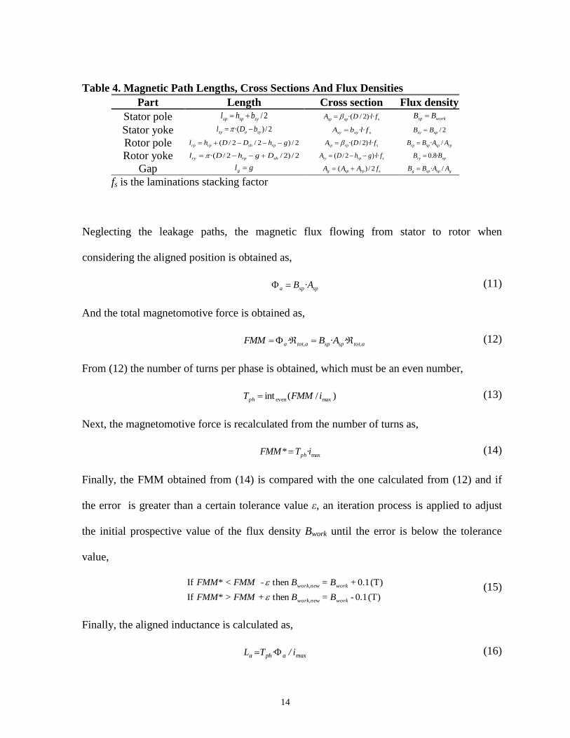
Table 4. Magnetic Path Lengths, Cross Sections And Flux Densities
Part Length Cross section Flux density
Stator pole 2/syspsp bhl sspsp flDA ·)·2/·(
worksp BB
Stator yoke 2/)·( syosy bDl ssysy flbA ·· 2/spsy BB
Rotor pole 2/) 2/2/( ghDDhl rpshrprp srprp flDA ·)·2/·(
rpspsprp AABB /·
Rotor yoke 2/)2/2/·( shrpry DghDl srpry flghDA ·)·2/(
spry BB ·8.0
Gap glg
srpspg fAAA 2/)( gspspg AABB /·
fs is the laminations stacking factor
Neglecting the leakage paths, the magnetic flux flowing from stator to rotor when
considering the aligned position is obtained as,
spspa AB · (11)
And the total magnetomotive force is obtained as,
atotspspatota ABFMM ,, ··· (12)
From (12) the number of turns per phase is obtained, which must be an even number,
)/(int maxeven iFMMTph (13)
Next, the magnetomotive force is recalculated from the number of turns as,
max·* iTFMM ph (14)
Finally, the FMM obtained from (14) is compared with the one calculated from (12) and if
the error is greater than a certain tolerance value ε, an iteration process is applied to adjust
the initial prospective value of the flux density Bwork until the error is below the tolerance
value,
(T) 0.1 - then + If
(T) 0.1 + then - If
workwork,new
workwork,new
= BBFMM* > FMM
= BBFMM* < FMM
(15)
Finally, the aligned inductance is calculated as,
maxapha i/·TL (16)

15
2. Stator coils dimensions. The stator coil area is the product of the coil width ωc by the coil
height hc and by a coil fill factor Ku, which can also be expressed as the product of the
conductors cross section area ac by half of the number of turns Tph per phase,
2···
ph
cccu
TahK (17)
The maximum value of ωc is obtained from the geometry in Fig. 2 as,
)
2·(
··
2
1Cl
D
N
Ds
s
c
(18)
Cl being the clearance between consecutive coils.
From (17) and (18) it results,
1
)2
·(·
··
Cl
D
N
D
K
Tah s
su
phc
c (19)
Next, since the coil must be placed between two consecutive stator poles and some extra
space is required to ensemble the coils, the stator pole height hsp is obtained from the coil
height hc by applying a security factor,
csp h·.h 21 (20)
3. Study of the fully unaligned position. Calculation of Lu.
From (1) and (2) it is clear that to obtain the output power and torque power of the machine,
both the aligned and fully unaligned inductances are required. In the unaligned position the
center of the interpolar rotor gap coincides with the midpoint of the stator pole. In this case
the leakage flux cannot be omitted, so the leakage paths must be calculated analytically. For
this purpose seven flux paths are analyzed [9] to calculate the unaligned inductance (see Fig.
6). For the i–th flux path the length lelement,i, cross section Aelement,i, magnetic field density
Belement,i, magnetic flux Φelement,I and reluctance ielement, of each element, as well as the total
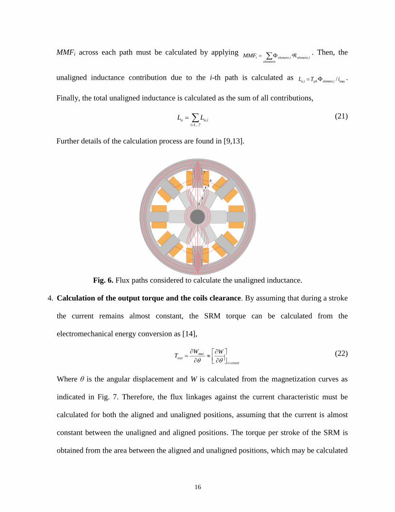
16
MMFi across each path must be calculated by applying
elements
ielementielementiMMF ,, ·. Then, the
unaligned inductance contribution due to the i-th path is calculated as max,, /· iTL ielementphiu .
Finally, the total unaligned inductance is calculated as the sum of all contributions,
7...1
,
i
iuu LL (21)
Further details of the calculation process are found in [9,13].
1
2
34
5
6
7
Fig. 6. Flux paths considered to calculate the unaligned inductance.
4. Calculation of the output torque and the coils clearance. By assuming that during a stroke
the current remains almost constant, the SRM torque can be calculated from the
electromechanical energy conversion as [14],
consti
mec
out
WWT
(22)
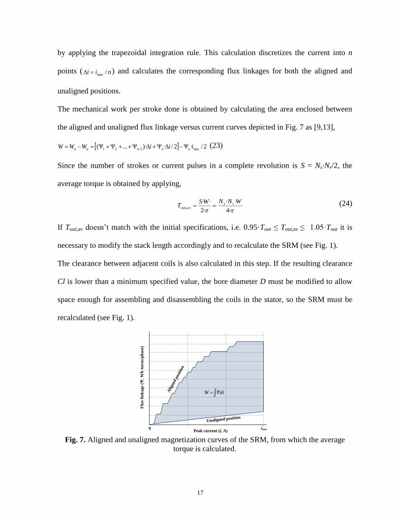
Where θ is the angular displacement and W is calculated from the magnetization curves as
indicated in Fig. 7. Therefore, the flux linkages against the current characteristic must be
calculated for both the aligned and unaligned positions, assuming that the current is almost
constant between the unaligned and aligned positions. The torque per stroke of the SRM is
obtained from the area between the aligned and unaligned positions, which may be calculated
17
by applying the trapezoidal integration rule. This calculation discretizes the current into n
points ( nii /max ) and calculates the corresponding flux linkages for both the aligned and
unaligned positions.
The mechanical work per stroke done is obtained by calculating the area enclosed between
the aligned and unaligned flux linkage versus current curves depicted in Fig. 7 as [9,13],
2/·2/·)·...( max121 iiiWWW unnua (23)
Since the number of strokes or current pulses in a complete revolution is S = Ns·Nr/2, the
average torque is obtained by applying,
·4
··
·2
··,
WNNWST rs
avout (24)
If Tout,av doesn’t match with the initial specifications, i.e. 0.95·Tout ≤ Tout,av ≤ 1.05·Tout it is
necessary to modify the stack length accordingly and to recalculate the SRM (see Fig. 1).
The clearance between adjacent coils is also calculated in this step. If the resulting clearance
Cl is lower than a minimum specified value, the bore diameter D must be modified to allow
space enough for assembling and disassembling the coils in the stator, so the SRM must be
recalculated (see Fig. 1).
Peak current (i, A)
Flu
x l
ink
age (Ψ
, W
b·t
urn
s/p
hase
)
ΨdiWAlign
ed p
osit
ion
Unaligned position
imax0
Fig. 7. Aligned and unaligned magnetization curves of the SRM, from which the average
torque is calculated.
18
D. Optimal SRM selection step
The selection of the optimal SRM is based on the solution achieving maximum torque. For all
combinations (βsp,βrp) explored during the design phase, the one achieving the maximum
average torque is selected.
THE MATLAB GUI DEVELOPED
This section describes the Matlab® graphical user interface (GUI) developed to assist the
students in designing the SRM and validating the results attained in the assignments of the
lecture sessions. The main window of the GUI consists of three main blocks, as illustrated in
Fig. 8.
The first block consists of a set of buttons allowing the user to run a new SRM calculation, plot
a drawing of the SRM or start a new design. In the second block the user sets the initial design
specifications, including Pout, nSRM, Ns/Nr, g, laminations material, Bwork,ini, imax, Jmax and the
geometric restrictions of the coils. The third block displays the output values provided by the
program, which include the final dimensions of the SRM and diverse performance parameters as
well as a graphical window which allows the user selecting among the B-H curve, the
magnetization curves of the designed SRM, and the set of (βsp,βrp) solutions explored during the
iterative design process.
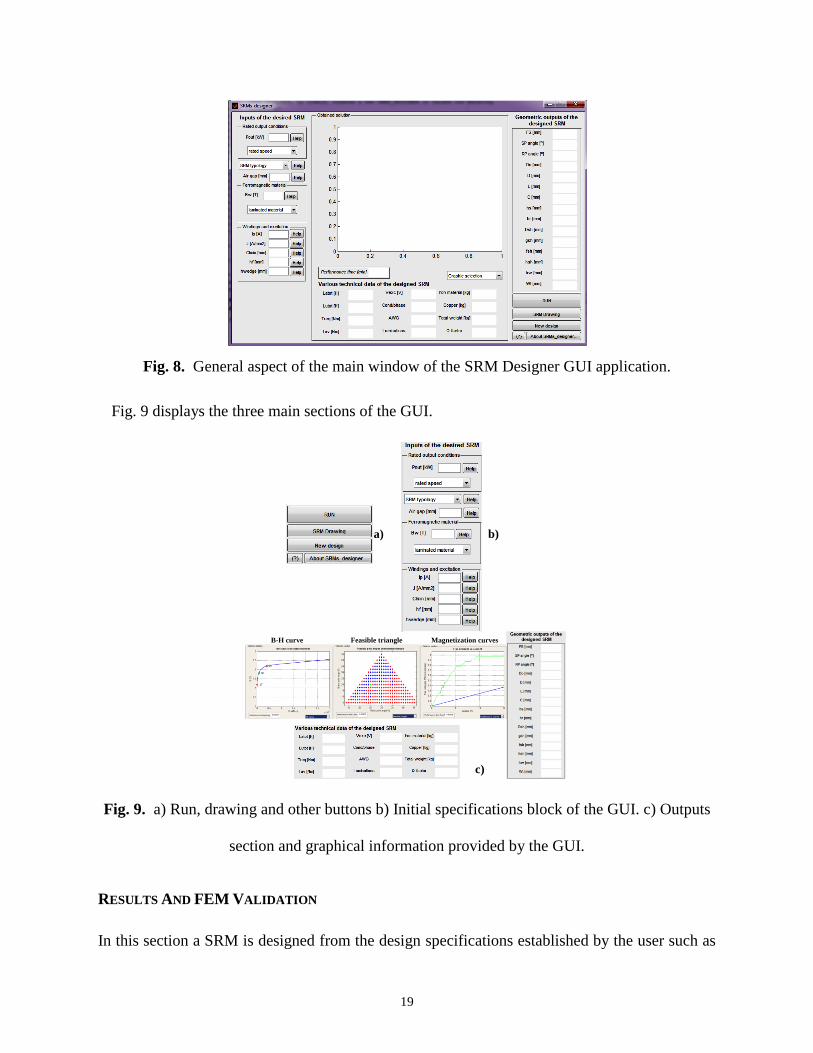
19
Fig. 8. General aspect of the main window of the SRM Designer GUI application.
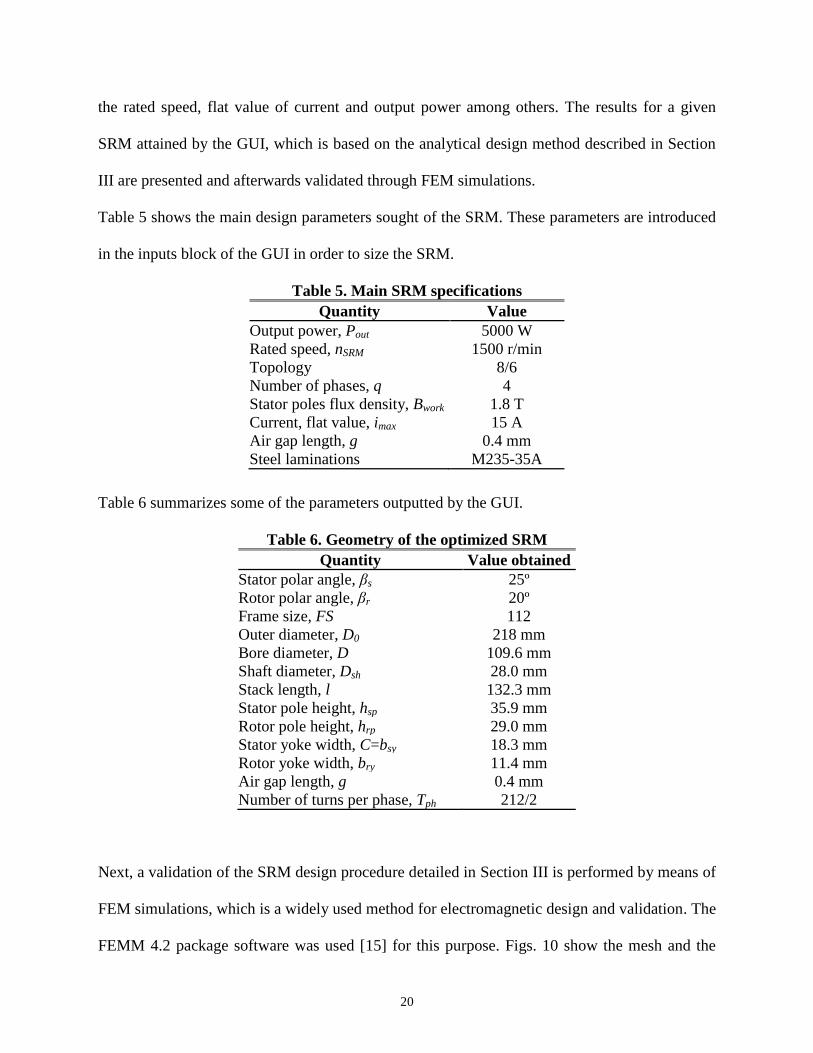
Fig. 9 displays the three main sections of the GUI.
B-H curve Feasible triangle Magnetization curves
c)
a) b)
Fig. 9. a) Run, drawing and other buttons b) Initial specifications block of the GUI. c) Outputs
section and graphical information provided by the GUI.
RESULTS AND FEM VALIDATION
In this section a SRM is designed from the design specifications established by the user such as
20
the rated speed, flat value of current and output power among others. The results for a given
SRM attained by the GUI, which is based on the analytical design method described in Section
III are presented and afterwards validated through FEM simulations.
Table 5 shows the main design parameters sought of the SRM. These parameters are introduced
in the inputs block of the GUI in order to size the SRM.
Table 5. Main SRM specifications
Quantity Value
Output power, Pout 5000 W
Rated speed, nSRM 1500 r/min
Topology 8/6
Number of phases, q 4
Stator poles flux density, Bwork 1.8 T
Current, flat value, imax 15 A
Air gap length, g 0.4 mm
Steel laminations M235-35A
Table 6 summarizes some of the parameters outputted by the GUI.
Table 6. Geometry of the optimized SRM
Quantity Value obtained
Stator polar angle, βs 25º
Rotor polar angle, βr 20º
Frame size, FS 112
Outer diameter, D0 218 mm
Bore diameter, D 109.6 mm
Shaft diameter, Dsh 28.0 mm
Stack length, l 132.3 mm
Stator pole height, hsp 35.9 mm
Rotor pole height, hrp 29.0 mm
Stator yoke width, C=bsy 18.3 mm
Rotor yoke width, bry 11.4 mm
Air gap length, g 0.4 mm
Number of turns per phase, Tph 212/2
Next, a validation of the SRM design procedure detailed in Section III is performed by means of
FEM simulations, which is a widely used method for electromagnetic design and validation. The
FEMM 4.2 package software was used [15] for this purpose. Figs. 10 show the mesh and the
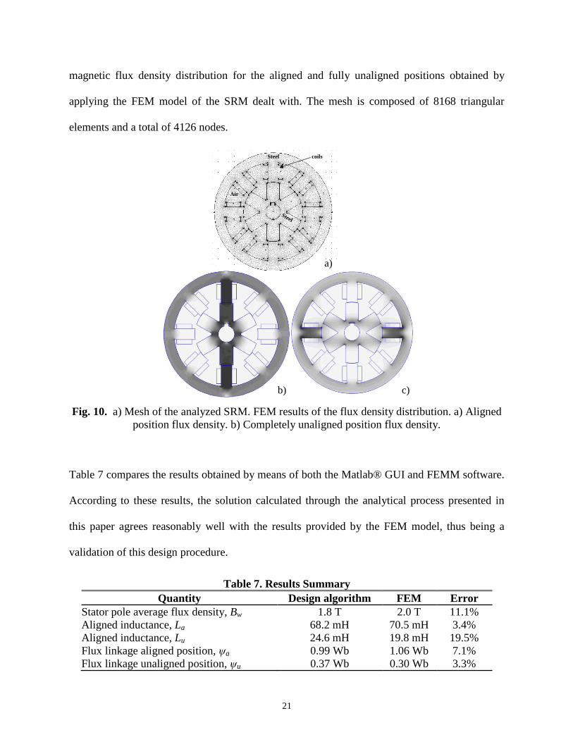
21
magnetic flux density distribution for the aligned and fully unaligned positions obtained by
applying the FEM model of the SRM dealt with. The mesh is composed of 8168 triangular
elements and a total of 4126 nodes.
Air
Steel
Steel
coils
a)
b) c)
Fig. 10. a) Mesh of the analyzed SRM. FEM results of the flux density distribution. a) Aligned
position flux density. b) Completely unaligned position flux density.
Table 7 compares the results obtained by means of both the Matlab® GUI and FEMM software.
According to these results, the solution calculated through the analytical process presented in
this paper agrees reasonably well with the results provided by the FEM model, thus being a
validation of this design procedure.
Table 7. Results Summary
Quantity Design algorithm FEM Error
Stator pole average flux density, Bw 1.8 T 2.0 T 11.1%
Aligned inductance, La 68.2 mH 70.5 mH 3.4%
Aligned inductance, Lu 24.6 mH 19.8 mH 19.5%
Flux linkage aligned position, ψa 0.99 Wb 1.06 Wb 7.1%
Flux linkage unaligned position, ψu 0.37 Wb 0.30 Wb 3.3%
22
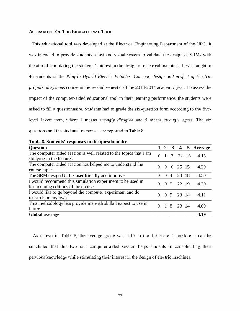
ASSESSMENT OF THE EDUCATIONAL TOOL
This educational tool was developed at the Electrical Engineering Department of the UPC. It
was intended to provide students a fast and visual system to validate the design of SRMs with
the aim of stimulating the students’ interest in the design of electrical machines. It was taught to
46 students of the Plug-In Hybrid Electric Vehicles. Concept, design and project of Electric
propulsion systems course in the second semester of the 2013-2014 academic year. To assess the
impact of the computer-aided educational tool in their learning performance, the students were
asked to fill a questionnaire. Students had to grade the six-question form according to the five-
level Likert item, where 1 means strongly disagree and 5 means strongly agree. The six
questions and the students’ responses are reported in Table 8.
Table 8. Students’ responses to the questionnaire.
Question 1 2 3 4 5 Average
The computer aided session is well related to the topics that I am
studying in the lectures 0 1 7 22 16 4.15
The computer aided session has helped me to understand the
course topics 0 0 6 25 15 4.20
The SRM design GUI is user friendly and intuitive 0 0 4 24 18 4.30
I would recommend this simulation experiment to be used in
forthcoming editions of the course 0 0 5 22 19 4.30
I would like to go beyond the computer experiment and do
research on my own 0 0 9 23 14 4.11
This methodology lets provide me with skills I expect to use in
future 0 1 8 23 14 4.09
Global average 4.19
As shown in Table 8, the average grade was 4.15 in the 1-5 scale. Therefore it can be
concluded that this two-hour computer-aided session helps students in consolidating their
pervious knowledge while stimulating their interest in the design of electric machines.
23
CONCLUSION
This paper has presented a computer-aided educational tool to assist the design process of a
SRM. The main objective of this tool is to help electrical engineering students during the design
process of a SRM, therefore fostering students’ motivation in the area of design of electrical
machines. The paper has covered the technical aspects of the design steps, a sizing example of a
SRM by using the educational tool presented here, and the results validation by means of FEM
simulations. Finally, an assessment of the students’ satisfaction about the usefulness and impact
on learning performance related to the use of this tool has been presented. The preliminary
results of the assessment summarized in Section VI related to students’ satisfaction with the
educational aspects of the educational tool suggest that it is a helpful tool for improving
students’ motivation and learning effectiveness in the design of electric machines.
REFERENCES
[1] B. Bilgin, A. Emadi, M. Krishnamurthy, ‘Design considerations for switched reluctance
machines with a higher number of rotor poles’, IEEE Trans. Ind. Electron., 59/10 (2012)
3745-3756.
[2] S. M. Lukic, A. Emadi, ‘State-switching control technique for switched reluctance motor
drives: theory and implementation’, IEEE Trans. Ind. Electron., 57/9 (2010), 2932–2938.
[3] V.P. Vujicic, ‘Minimization of torque ripple and copper losses in switched reluctance drive’,
IEEE Trans. Power Electron. 27/1 (2012), 388–399.
[4] S. P. Nikam, V. Rallabandi, B. G. Fernandes, A High-torque-density permanent-magnet free
motor for in-wheel electric vehicle application’, IEEE Trans. Ind. Appl., 48/6 (2012), 2287-
2295.
[5] J.-R. Riba, A. Garcia, and L. Romeral, ‘A computer experiment to simulate the dynamic
behavior of electric vehicles driven by switched reluctance motors’, Int. Jour. Elect. Eng.
Edu., 51/4 (2014), 368-382.
[6] C. Gencer, M. Gedikpinar, ‘A computer-aided educational tool for induction motors’, Comp.
Appl. Eng. Edu., 20/3 (2012), pp. 503–509.
24
[7] H. Isfahani, S. Vaez-Zadeh, S. Hasanzadeh, ‘An educational toolbox for performance
analysis of line-start permanent magnet synchronous motors’, Comp. Appl. Eng. Edu., 22/3
(2014), 452–462.
[8] R. J. Romero-Troncoso, A. Garcia-Perez, E. Cabal-Yepez, R. A. Osornio-Rios,
‘Experimental system for teaching induction motor faults during the startup transient and
steady state’, Comp. Appl. Eng. Edu., 22/1 (2014), 33–38.
[9] R. Krishnan, Switched reluctance motor drives. Modeling, simulation, analysis, design and
applications, Ed. 2001, CRC Press, Boca Raton, Florida, 2001.
[10] IEC 60072-1. Dimensions and output series for rotating electrical machines - Part 1: Frame
numbers 56 to 400 and flange numbers 55 to 1080. Publication date: 1991-02-01
[11] ABB. [online] URL: <http://www.abb.es/product/es/> [Consult: 20/11/2014].
[12] R. Arumugam, J. F. Lindsay, R. Krishnan, ‘Sensitivity of pole arc/pole pitch ratio on
switched reluctance motor performance’, in Proc. IEEE IAS Ann. Mtg., Vol. 1, pp. 50-54,
Pittsburgh, Oct. 1988.
[13] P. Vijayraghavan, ‘Design of switched reluctance motors and development of a universal
controller for switched reluctance and permanent magnet brushless dc motor drives’, PhD
Dissertation, Blacksburg, Virginia, Nov. 15, 2001.
[14] T. J. E. Miller, Electronic Control of Switched Reluctance Machines, Newnes, Ed. 2001,
Jordan Hill, Oxford, 2001.
[15] D. C. Meeker, Finite Element Method Magnetics, Version 4.2 (25Aug2013 Build),
http://www.femm.info.