Embed Size (px)
Citation preview
Research ArticleThe Application of PSO-AFSA Method inParameter Optimization for Underactuated AutonomousUnderwater Vehicle Control
Chunmeng Jiang Lei Wan Yushan Sun and Yueming Li
Science and Technology on Underwater Vehicle Laboratory Harbin Engineering University Harbin 150001 China
Correspondence should be addressed to Yushan Sun sunyushanhrbeueducn
Received 3 April 2017 Accepted 6 July 2017 Published 21 August 2017
Academic Editor Nicolas Hudon
Copyright copy 2017 Chunmeng Jiang et al This is an open access article distributed under the Creative Commons AttributionLicense which permits unrestricted use distribution and reproduction in any medium provided the original work is properlycited
In consideration of the difficulty in determining the parameters of underactuated autonomous underwater vehicles in multi-degree-of-freedom motion control a hybrid method that combines particle swarm optimization (PSO) with artificial fish schoolalgorithm (AFSA) is proposed in this paper The optimization process of the PSO-AFSA method is firstly introduced With thecontrol simulation models in the horizontal plane and vertical plane the PSO-AFSAmethod is elaborated when applied in controlparameter optimization for an underactuated autonomous underwater vehicle Both simulation tests and field trials were carried outto prove the efficiency of the PSO-AFSAmethod in underactuated autonomous underwater vehicle control parameter optimizationTheoptimized control parameters showed admirable control quality by enabling the underactuated autonomous underwater vehicleto reach the desired states with fast convergence
1 Introduction
The rapid development of artificial intelligence automaticcontrol and simulation technology has brought significantprogress to autonomous underwater vehicle (AUV) technolo-gies [1] AUVs have been used in various fields including thedevelopment of marine mineral resources [2] topographicalsurveying [3] hydrological information collection [4] damand pipeline detection [5] and relay communication [6]With respect tomultiple parameters strong nonlinearity andstrong coupling effect of underactuated AUV control systemhow well an AUV completes its task depends on not onlythe sensors and actuators equipped but also reliable controlperformance [7]
In practice however the design of underactuated AUVcontroller depends on the designerrsquos personal experienceThe control parameters are often determined with the cut-and-try method which is not only time-consuming but alsodifficult to get the optimal or even satisfying control param-eters Especially when multiple degrees of freedom are
involved in AUVmotion control experience-based trials willbecome a more difficult problem For the resolution of con-trol parameter optimization colony algorithm [8] immunealgorithm [9 10] and PSO [11] had been adopted butthey all fail in engineering practice due to complicatedcoding process tendency to be stuck with local extremum orinability to satisfy multi-degree-of-freedom motion control
For this reason in this paper combining PSO with AFSAis proposed to optimize underactuated AUV control param-eters and also to provide an effective solution to parameteroptimization for nonlinear control systems
When applied to control parameter optimization PSO isnoticeable for fast convergence [12] high efficiency andparallel searching ability but it is likely to be stuck with localextremum and miss the global extremum AFSA is highlytolerant with algorithm parametersrsquo initial value and is rec-ommended for its strong global searching ability though it isinferior to PSO in terms of convergence efficiency [13] PSO iscombined with AFSA in this paper with the fast convergenceof PSO making up for that of AFSA and the global searching
HindawiMathematical Problems in EngineeringVolume 2017 Article ID 6327482 14 pageshttpsdoiorg10115520176327482
2 Mathematical Problems in Engineering
(my best position)
(the best position of the swarm)Where I am now
(a)(b)
(c)
Pbest ti
Gbest ti
Vti
(a)(b)(c)
a1 middot rand() middot (Pbest ti minus Xti )
a2 middot rand() middot (Gbest ti minus Xti )
wVti
Figure 1 Particle update
ability of AFSA solving PSOrsquos tendency of being stuck withlocal extremum so that the two can collaborate in parameteroptimization for underactuated AUV control and achieveefficient and desirably optimized results
This paper is organized as follows The second sectionsummarizes the principles and procedures of PSO AFSAand PSO-AFSA method respectively The frames of motioncontrol are established in the third section where the researchobject is introduced the horizontal and vertical motionmodels are established and how the PSO-AFSA method isapplied to underactuated AUV control parameter optimiza-tion is expounded The simulation tests are carried out inthe fourth section for underactuated AUV motion control inthe horizontal plane and the vertical plane The field trialsare carried out in the fifth section Both the simulation testsand field trials have justified the efficiency of the PSO-AFSAmethod in parameter optimization for underactuated AUVcontrol
2 Algorithm Overview
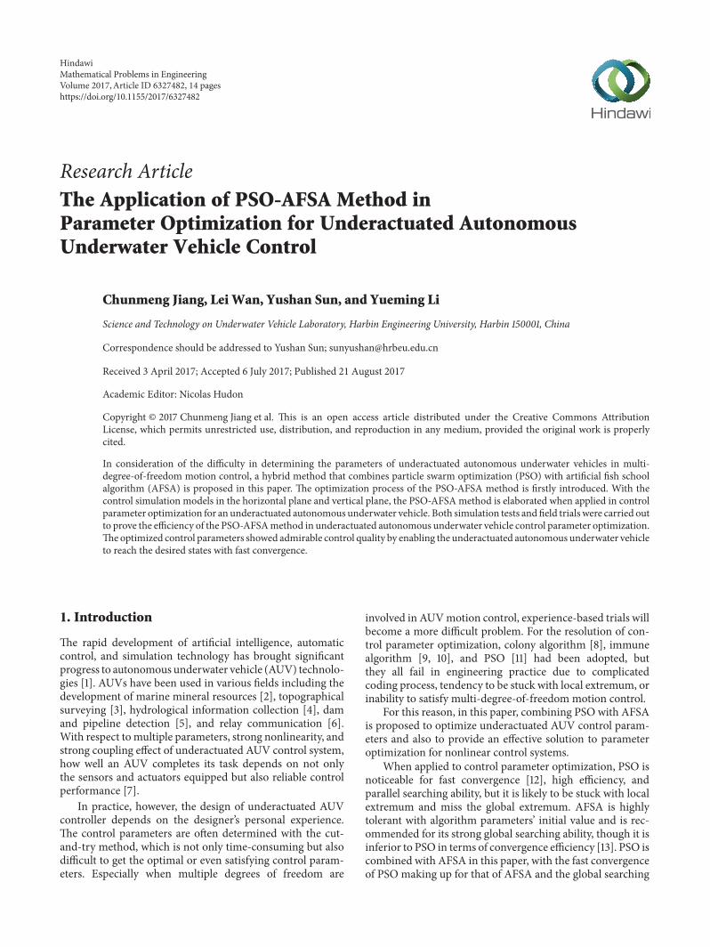
21 PSO In particle swarm optimization each particle in thesearching space represents a potential solution to the problemto be optimized Each particle corresponds to a fitness valuedetermined by the function to be optimized [14] During theoptimization each particle is subordinate to a velocity vectorthat determines the direction and distance that they can flyBefore reaching the optimal solution particles keep updatingthemselves by following two values as shown in Figure 1 Thefirst value is called individual extremum namely the optimalsolution that each individual particle has found by far Thesecond value is called global extremum namely the optimalsolution that the entire swarm has ever found Each particleupdates their velocity and position by
119881119905+1119894 = 119908 sdot 119881119905119894 + 1198861 sdot rand () sdot (119875119887119890119904119905119905119894 minus 119883119905119894) + 1198862sdot rand () sdot (119866119887119890119904119905119905119894 minus 119883119905119894)
(1)
119883119905+1119894 = 119883119905119894 + 119881119905+1119894 (2)
where 119908 is the inertia weight 119881119905119894 is the velocity of particle119894 at time 119905 119883119905119894 is the position of particle 119894 at time 119905 119875119887119890119904119905119905119894is the optimal position that individual particle 119894 has everfound 119866119887119890119904119905119905119894 is the optimal position that the entire swarmhas ever found and rand() is a random value from [0 1]1198861 and 1198862 are accelerating coefficients introduced to adjustthe maximum step length that the participles fly towardsthe individual extremum and global extremum With smallvalues 1198861 and 1198862 may lead the particles away from the targetarea while large values of the accelerating coefficients willmake the particles rush to the target area or fly over the targetarea In addition the particles are limited with the presetmaximum flying velocity 119881max whose larger value guaranteesthe global searching ability of the entire swarm Boundaryconditions are also set to keep the swarmwithin the searchingspace
Formula (1) consists of three parts 119908 sdot 119881119905119894 indicates eachindividual particlersquos tendency to fly following their previousdirection and velocity which is called the ldquoinertiardquo part1198861 sdot rand() sdot (119875119887119890119904119905119905119894 minus 119883119905119894) reflects each individual particlersquostendency to fly towards their respective optimal positionwhich is known as the ldquocognitionrdquo part 1198862 sdot rand() sdot (119866119887119890119904119905119905119894 minus119883119905119894) shows each individual particlersquos tendency to fly towardsthe optimal position the entire swarm has ever experiencedwhich is named as the ldquosocietyrdquo part
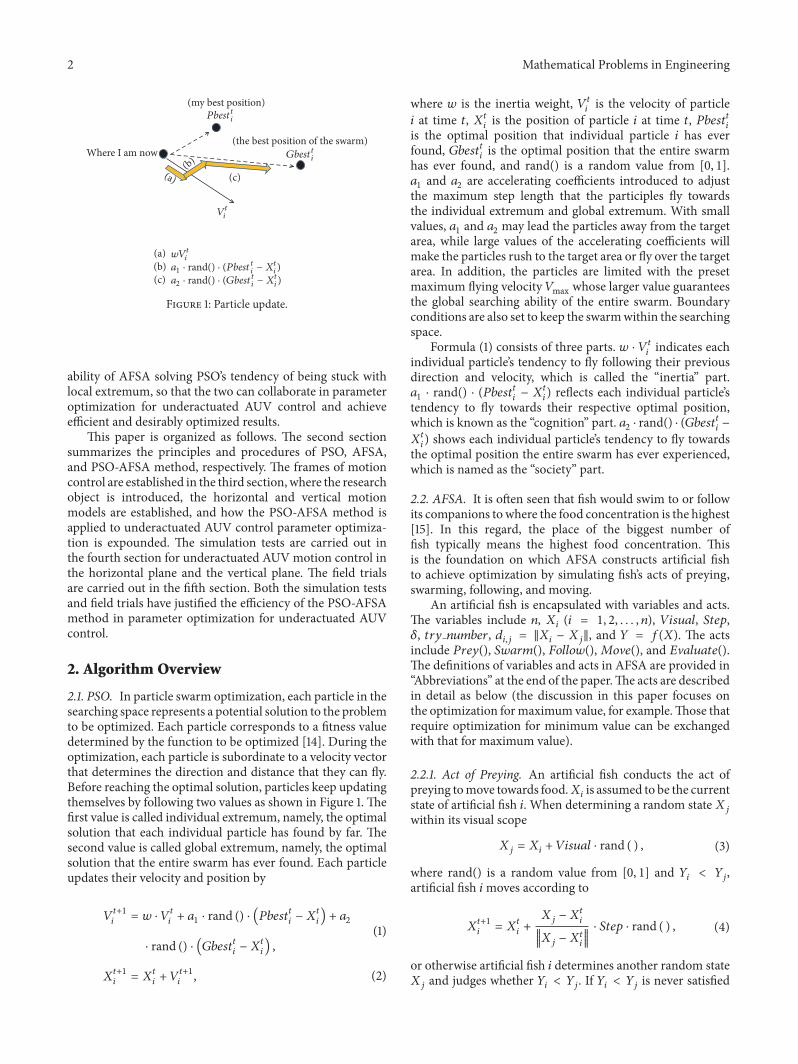
22 AFSA It is often seen that fish would swim to or followits companions to where the food concentration is the highest[15] In this regard the place of the biggest number offish typically means the highest food concentration Thisis the foundation on which AFSA constructs artificial fishto achieve optimization by simulating fishrsquos acts of preyingswarming following and moving
An artificial fish is encapsulated with variables and actsThe variables include 119899 119883119894 (119894 = 1 2 119899) 119881119894119904119906119886119897 119878119905119890119901120575 119905119903119910 119899119906119898119887119890119903 119889119894119895 = 119883119894 minus 119883119895 and 119884 = 119891(119883) The actsinclude 119875119903119890119910() 119878119908119886119903119898() 119865119900119897119897119900119908()119872119900V119890() and 119864V119886119897119906119886119905119890()The definitions of variables and acts in AFSA are provided inldquoAbbreviationsrdquo at the end of the paperThe acts are describedin detail as below (the discussion in this paper focuses onthe optimization formaximum value for exampleThose thatrequire optimization for minimum value can be exchangedwith that for maximum value)
221 Act of Preying An artificial fish conducts the act ofpreying tomove towards food119883119894 is assumed to be the currentstate of artificial fish 119894 When determining a random state119883119895within its visual scope
119883119895 = 119883119894 + 119881119894119904119906119886119897 sdot rand ( ) (3)
where rand() is a random value from [0 1] and 119884119894 lt 119884119895artificial fish 119894moves according to
119883119905+1119894 = 119883119905119894 + 119883119895 minus 11988311990511989410038171003817100381710038171003817119883119895 minus 11988311990511989410038171003817100381710038171003817sdot 119878119905119890119901 sdot rand ( ) (4)
or otherwise artificial fish 119894 determines another random state119883119895 and judges whether 119884119894 lt 119884119895 If 119884119894 lt 119884119895 is never satisfied
Mathematical Problems in Engineering 3
Visual
Step
XV
X
Xnext
Figure 2 Artificial fish school algorithm
after artificial fish 119894 tries 119905119903119910 119899119906119898119887119890119903 times artificial fish 119894moves randomly according to
119883119905+1119894 = 119883119905119894 + 119881119894119904119906119886119897 sdot rand ( ) (5)
222 Act of Swarming A school of fish would swarmnaturally to survive or keep themselves away from danger InAFSA all artificial fish shall move towards the center oftheir companions and avoid overcrowding in the meantime119883119894 is assumed to be the current state of artificial fish 119894When detecting the number of companions 119899119891 within itsneighborhood and their central position 119883119888 with 119884119888119899119891 gt120575 sdot 119884119894 which means the food concentration is high and it isnot overcrowding at the central position 119883119888 artificial fish 119894moves towards119883119888 according to
119883119905+1119894 = 119883119905119894 + 119883119888 minus 1198831199051198941003817100381710038171003817119883119888 minus 1198831199051198941003817100381710038171003817 sdot 119878119905119890119901 sdot rand ( ) (6)
or otherwise artificial fish 119894 conducts the act of preying223 Act of Following An artificial fish conducts the actof following to move towards the neighboring artificial fishwhose position shows the highest food concentration Theact of following means moving towards the best companionin an artificial fishrsquos neighborhood 119883119894 is assumed to be thecurrent state of artificial fish 119894When detecting119883119895 that has thehighest food concentration119884119895 within its neighborhood (119889119894119895 lt119881119894119904119906119886119897) and with 119884119895119899119891 gt 120575 sdot 119884119894 which means the foodconcentration is satisfyingly high and it is not overcrowdingat119883119895 artificial fish 119894moves towards119883119895 according to
119883119905+1119894 = 119883119905119894 + 119883119895 minus 11988311990511989410038171003817100381710038171003817119883119895 minus 11988311990511989410038171003817100381710038171003817sdot 119878119905119890119901 sdot rand ( ) (7)
or otherwise artificial fish 119894 conducts the act of preying
224 Act of Moving As a default of the act of preying the actof moving means that artificial fish 119894 randomly determinesa state within its visual scope and moves towards the stateaccording to
119883119905+1119894 = 119883119905119894 + 119881119894119904119906119886119897 sdot rand ( ) (8)
225 Act of Evaluating As shown in Figure 2 in the processof optimization an artificial fish evaluates the acts of preyingswarming following and moving before determining andconducting the best act based on its evaluation so as to reachthe position of higher food concentration
In addition a bulletin board is introduced in AFSA torecord the optimal state the entire school has ever expe-rienced After each time of iteration each artificial fishcompares its individual state with that recorded in thebulletin board If the state of an individual artificial fish isbetter than that recorded in the bulletin board the bulletinrecord will be updated or otherwise the bulletin record willremain When the iteration is finished the bulletin record isthe expected optimal solution
23 PSO-AFSA Combining PSOwith AFSA the PSO-AFSAmethod takes advantage of the rapid convergence abilityof PSO and the strong global searching ability of AFSA toprovide more desirable optimized results
The PSO-AFSA method works in accordance with thefollowing procedures shown in Figure 3
Step 1 (initialization) The particle swarm 1198751199001199011 artificialfish school 1198751199001199012 size of the particle swarm 1198731 andsize of the artificial fish school 1198732 are firstly definedIndividual particles and artificial fishes are generated ran-domly within the feasible domain of the parameters tobe optimized 1198861 1198862 119881119894119904119906119886119897 119878119905119890119901 120575 and 119905119903119910 119899119906119898119887119890119903
4 Mathematical Problems in Engineering
Define Pop1 Pop2 N1 and N2
The particle swarm updates according to formulas (1) and (2) and provides PSO-Gbest The artificial fish school realizesoptimization according to Section 22 and provides theoptimized result AFSA_best
Compare the fitness value reported back from the particleswarm and the artificial fish school with the better value recorded in the global bulletin board (PSO-AFSA_best)
AFSA_best = PSO_Gbest
If PSO_Gbest gt AFSA_best If AFSA_best gt PSO_Gbest
PSO_Gbest = AFSA_best
Whether the termination condition is satisfied
Yes
Output PSO-AFSA_best
No
Randomly generate individual particles and artificial fishesSet a1 a2 Visual Step and try_number
Figure 3 PSO-AFSA procedures
(whose definitions are provided in ldquoAbbreviationsrdquo) are alsoset
Step 2 (PSO) Each particle in the swarm updates itselfaccording to formulas (1) and (2) After each time of iterationeach individual extremum PSO Pbest and the global optimalextremum PSO Gbest are obtained
Step 3 (AFSA) The artificial fish school realizes optimizationaccording to Section 22 and provides the optimized resultAFSA best after each time of iteration
Step 4 (bulletin) A global bulletin board is introduced tocompare the fitness value reported back from the particleswarm and the artificial fish school with the better valuerecorded in the global bulletin board (PSO-AFSA best)When PSO Gbest is better than AFSA best the optimiza-tion result from AFSA is replaced by PSO Gbest whichcan improve the optimization efficiency of AFSA WhenAFSA best is better than PSO Gbest the optimization result
fromPSO is replaced byAFSA best which can strengthen theglobal searching ability of PSO
Step 5 (termination conditions) Steps 2ndash4 repeat till thetermination condition is satisfied (such as times of iterationor error tolerance)
Step 6 (output) When the optimization completes PSO-AFSA best recorded on the bulletin board is the optimizedresult expected
3 Frames Controller andMotion Models of the AUV
31 Construction and Transformation of Frames In accor-dance with the standard symbol system the inertial frame119864 minus 120585120578120577 and the body frame 119866 minus 119909119910119911 [16] are constructed asshown in Figure 4
The transformation between the inertial frame and thebody frame complies with [17]
Mathematical Problems in Engineering 5
E
x
y
z
O
Figure 4 Inertial frame and body frame
[[[
119909119910119911]]]= 119879[[
[
120585120578120589]]]
119879 = [[[
cos120595 cos 120579 sin120595 cos 120579 minus sin 120579cos120595 sin 120579 sin120593 minus sin120595 cos120593 sin120595 sin 120579 sin120593 + cos120595 cos120593 cos 120579 sin120593cos120595 sin 120579 cos120593 + sin120595 sin120593 sin120595 sin 120579 cos120593 minus cos120595 sin120593 cos 120579 cos120593
]]]
(9)
where 119879 is the transformation matrix 120595 is the heading angle120579 is the trimming angle and 120593 is the heeling angle
32 Profile of Research Object Designed with conventionalstreamline the research object weighs 183 kg 255m longwith the cruising speed of 3 kn It is equipped with onethruster at the stern together with one rudder and oneelevator The underactuated AUV can realize movement infive degrees of freedom including the surge sway and heavedirections as well as the pitch and yaw dimensions Thegravity center of the AUV is the origin of the body frame andits weight is equated to its buoyancy The buoyancy center is002m over the gravity center in a vertical line The AUV isassumed to be in a symmetric structure in left-right front-rear and top-bottom dimensions
The AUV adopts sigmoid-function control method thatintegrates fuzzy control with PD control structure [18] Dueto the simple structure and demand on small number ofparameters the sigmoid-function control method has beensuccessfully applied to different models of AUV motioncontrol and received admirable control result Numerousfield trials have also justified the feasibility and effectivenessof sigmoid-function method in underwater vehicle motioncontrol In practice however the control parameters ofsigmoid-function method mostly come from the designerrsquospersonal experience and trials The adjustment process is notonly time-consuming but also difficult to achieve satisfactorycontrol parameters For the interest of efficient parameteradjustment and more desirable test results it is necessary tooptimize the control parameters of sigmoid-functionmethodwith PSO-AFSA method
The sigmoid-function controller is expressed as [19]
119891 = 21 + exp (minus1198961119890 minus 1198962 119890) minus 1 (10)
where 1198961 and 1198962 are the control parameters 119890 and 119890 arerespectively the deviation and rate of deviation changebetween the desired value and actual value of the input 119891 isthe control output
33 AUV Motion Models
331 Motion Model for the Horizontal Plane The kinematicequation of the research object in the horizontal plane is [20]
120585 = 119906 cos120595 minus V sin120595120578 = 119906 sin120595 + V cos120595
= 119903(11)
The kinetic equation of the research object in the horizon-tal plane is [20]
(119898 minus 119883) = (119898 minus 119884V) V119903 + (119883119906 + 119883119906|119906| |119906|) 119906 + 119883(119898 minus 119884V) V = minus (119898 minus 119883) 119906119903 + (119884V + 119884V|V| |V|) V(119868119911 minus 119873 119903) 119903 = minus (119883 minus 119884V) 119906V + (119873119903 + 119873119903|119903| |119903|) 119903 + 119873
(12)
where 119906 and V are the AUVrsquos linear velocity in the surge andsway directions 119903 is the AUVrsquos angular velocity in the yawdimension 119883 is the force in the surge direction 119873 is themoment in the yaw dimension119898 is themass of the AUV and119883 and 119884V are hydrodynamic coefficientsThe hydrodynamiccoefficients are obtained with planar motion mechanism inthe circulating water flume as shown in Figure 5 The hydro-dynamic tests carried out and hydrodynamic coefficients ofthe AUV in the horizontal plane are respectively provided inTables 1 and 2
It can be inferred from formula (11) that there is no inputin the sway direction whichmeans that the AUV is obviouslyan underactuated system
6 Mathematical Problems in Engineering
Table 1 Types of hydrodynamic test and coefficients
Types of hydrodynamic test Hydrodynamic coefficientsOblique towing test 119884V 119885119908119872119908119873V
Pure heave test 119885119872Pure transverse oscillation test 119884V119873V
Pure pitch oscillation test 119885119902 119885 119902119872119902119872 119902Pure yaw oscillation test 119884119903 119884 119903119873119903119873 119903Pure roll oscillation test 119870119901 119870The theoretical calculation empirical formula estimation 119883119883119906|119906|119883119902|119902|119883119903|119903|119883V119903119883119908119902 119884V|V| 119885119908|119908| 119885119902|119902| 119885119908119902119872119902|119902|119872119908|119908|119872119908119902119873V|V|119873119903|119903|
Table 2 AUV body and hydrodynamic coefficients (horizontalplane)
119898 1830 kg119868119911 9455 kgsdotm2119871 255m119883 minus1341 kg119884V minus26134 kg119873 119903 minus8848 kgsdotm2119883119906 0119884V minus14983 kgs119873119903 minus25308 kgsdotm2(ssdotrad)119883119906|119906| minus1666 kgm119884V|V| minus55610 kgm119873119903|119903| minus7975 kgsdotm2rad2
Figure 5 Circulating water flume for hydrodynamic tests
332 Motion Model for the Vertical Plane The kinematicequation of the research object in the vertical plane is [20]
120585 = 119906 cos 120579 + 119908 sin 120579120577 = minus119906 sin 120579 + 119908 cos 120579120579 = 119902
(13)
The kinetic equation of the research object in the verticalplane is [20]
(119898 minus 119883) = minus (119898 minus 119885) 119906119908 + (119883119906 + 119883119906|119906| |119906|) 119906minus (119882 minus 119861) sin 120579 + 119883
(119898 minus 119885) = 119885 119902 119902 + (119898 minus 119883) 119906119908+ (119885119908 + 119885119908|119908| |119908|) 119908+ (119882 minus 119861) cos 120579
(119868119910 minus119872 119902) 119902 = 119872 + (119883 minus 119885) 119906119908+ (119872119902 +119872119902|119902| 10038161003816100381610038161199021003816100381610038161003816) 119902 + 119911119861119861 sin 120579+119872
(14)
where 119906 and 119908 are the AUVrsquos linear velocity in the surge andheave directions 119902 is the AUVrsquos angular velocity in the pitchdimension 119883 is the force in the surge direction 119872 is themoment in the pitch dimension119898 is the mass of the AUV119882is the weight of the AUV 119861 is the buoyancy of the AUV and119911119861 is the vertical distance between the buoyancy center andthe gravity center The hydrodynamic coefficients such as119883and 119884V have the same definitions as those in the horizontalmotion modelThe hydrodynamic coefficients of the AUV inthe vertical plane are listed in Table 3
It can be inferred from formula (14) that there is noinput in the heave direction which means that the AUV isobviously an underactuated system
4 Control Simulations
In order to verify the PSO-AFSA method proposed the con-trol simulations are carried out with the platform of Matlab86 in the horizontal plane and vertical plane respectivelyThe property parameters and hydrodynamic coefficients ofthe AUV are listed in Tables 2 and 3
41 Simulation in the Horizontal Plane When applied tocontrol parameter optimization in the horizontal plane thePSO-AFSA method is firstly written in the m file and the
Mathematical Problems in Engineering 7
Best fitness valu = minus694918Best u1 = 98 u2 = 54
minus120
minus100
minus80
minus60
Best
fitne
ss v
alue
5 10 2015Iteration time(a)
Best fitness valu = minus019
Best Ψ1 = 95 Ψ2 = 76
5 10 2015Iteration time
minus05
minus04
minus03
minus02
minus01
00
Best
fitne
ss v
alue
(b)
Figure 6 Control parameter optimization results in the horizontal plane
Table 3 AUV body and hydrodynamic coefficients (vertical plane)
119898 1830 kg119868119910 9494 kgsdotm2119871 255m119911119861 002m119882 17934N119861 17934N119883 minus1341 kg119885 minus26173 kg119872 119902 minus8825 kgsdotm2119883119906 0119885119908 minus14237 kgs119872119902 minus22114 kgsdotm2(ssdotrad)119883119906|119906| minus1666 kgm119885119908|119908| minus43216 kgm119872119902|119902| minus6325 kgsdotm2rad2
simulation model is then constructed in Simulink as shownin Figure 17
Since the AUV realizes movement in three degrees offreedom in the horizontal plane the PSO-AFSA methodimplements parameter optimization for119906 and120595 control at thesame time 1205821199061 and 1205821199062 the parameters for velocity controlare optimized based on the deviation and rate of deviationchange between the desired velocity value and actual velocityvalue 1205821205951 and 1205821205952 the parameters for heading angle controlare optimized based on the deviation and rate of deviationchange between the desired heading angle value and actualheading angle value
The indicator function of Integral of Time-WeightedAbsolute Value of the Error (ITAE) is adopted in this paperto evaluate the optimization of control parameters ITAE
gives little consideration to the initial deviation but putsmore emphasis on the overshooting and adjusting timeITAE is commonly used in the control fields because itcomprehensively reflects the rapidity and accuracy of thecontrol systemThe function to be optimized is as follows [21]
min1205821 12058221205823 1205824
Φ = int1199050119905 |119890 (119905)| 119889119905 (15)
where 119890 stands for the error between the desired and actualinputs and 1205821 1205822 1205823 and 1205824 are the control parameters to beoptimized
For each time of iteration in PSO-AFSA optimizationthe two sets of control parameters 1205821199061 1205821199062 and 1205821205951 1205821205952reported back from PSO and AFSA are stored in Matlabworkspace and then input to the four 119868119899modules of the sim-ulation control model in SimulinkThe simulation time is setto be 50 s after which the fitness value of min1205821199061 1205821199062 1205821205951 1205821205952Φis reported back from the 119874119906119905 module to Matlab workspaceto enable the PSO-AFSA method to continue with theoptimization
In the optimization of underactuated AUV controlparameters for the horizontal plane the PSO-AFSA methodis set as follows 1198731 = 20 1198861 = 1198862 = 1 1198732 = 20119881119894119904119906119886119897 = 5 119878119905119890119901 = 05 120575 = 055 and 119905119903119910 119899119906119898119887119890119903 = 4Based on the experience in practice 0 lt 1205821199061 1205821199062 1205821205951 1205821205952 le10 The simulation model is set with fixed-step solver withthe sample time of 001 s In addition disturbing items arealso included in the simulation model with the currentvelocity 119906119888 = 01ms and current angle 119886119888 = 05∘ Figure 6shows the optimization results for AUVmotion control in thehorizontal plane with the desired velocity 119906119889 = 15ms anddesired heading angle 120595119889 = 20∘
It can be seen in Figure 6 that the optimized parametersfor velocity control are 1205821199061 = 98 and 1205821199062 = 54 and thosefor heading angle control are 1205821205951 = 95 and 1205821205952 = 76 Thebest fitness value comes frommin1205821199061 1205821199062 1205821205951 1205821205952Φ at the end of
8 Mathematical Problems in Engineering
Desired valueSimulation result
00
05
10
15
20
u (m
s)
40 60 80 10020Time (s)
Figure 7 Velocity control result with 1205821199061 1205821199062
Desired valueSimulation result
20 40 60 80 1000Time (s)
0
5
10
15
20
25
Hea
ding
angl
e (de
gree
)
Figure 8 Heading angle control result with 1205821205951 1205821205952
each time of iteration Figures 7 and 8 show respectively thecontrol result of velocity and heading angle with the optimalparameters 1205821199061 1205821199062 1205821205951 1205821205952
As shown in the simulation results the two sets of controlparameters 1205821199061 1205821199062 and 1205821205951 1205821205952 optimized by the PSO-AFSAmethod enable the AUV to achieve the desired velocityand heading angle value within a very short period of time ina steady manner
42 Simulation in the Vertical Plane When applied to controlparameter optimization in the vertical plane the PSO-AFSAmethod is also firstly written in the m file and the simulationmodel is then constructed in Simulink as shown in Figure 18
Since the AUV realizes movement in three degrees offreedom in the vertical plane the PSO-AFSA method imple-ments parameter optimization for 119906 and 120579 control at the sametime The same as the optimization in the horizontal place1205821199063 and 1205821199064 are optimized based on the deviation and rateof deviation change between the desired and actual velocityvalues 1205821205791 and 1205821205792 are optimized based on the deviationand rate of deviation change between the desired and actualtrimming angle values
The indicator function of Integral of Time-WeightedAbsolute Value of the Error (ITAE) is also adopted for theoptimization of the control parameters in the vertical planeThe simulation procedures and settings are the same as thosefor the horizontal plane
Mathematical Problems in Engineering 9
Best fitness valu = minus39341
Best u3 = 91 u4 = 45
minus6
minus5
minus4
minus3Be
st fit
ness
val
ue
5 10 2015Iteration time(a)
Best fitness valu = minus01041
Best 1 = 95 2 = 59
minus015
minus010
minus005
Best
fitne
ss v
alue
5 10 2015Iteration time(b)
Figure 9 Control parameter optimization results in the vertical plane
Desired valueSimulation result
20 60 8040 100Time (s)
00
05
10
15
20
u (m
s)
Figure 10 Velocity control result with 1205821199063 1205821199064
In the optimization of underactuated AUV controlparameters for the vertical plane 1198731 1198861 1198862 1198732 119881119894119904119906119886119897119878119905119890119901 120575 and 119905119903119910 119899119906119898119887119890119903 have the same settings as those forthe horizontal plane Based on the experience in practice0 lt 1205821199063 1205821199064 1205821205791 1205821205792 le 12 The simulation model is setwith fixed-step solver with the sample time of 001 s Againdisturbing items are also included in the simulation modelwith the current velocity 119906119888 = 01ms and current angle119886119888 = 05∘ Figure 9 shows the optimization results for AUVmotion control in the vertical plane with the desired velocity119906119889 = 15ms and desired heading angle 120579119889 = minus5∘
It can be seen that the optimized parameters for velocitycontrol are 1205821199063 = 91 and 1205821199064 = 45 and those for trimmingangle control are 1205821205791 = 95 and 1205821205792 = 59 Figures 10 and 11
Desired valueSimulation result
20 60 8040 100Time (s)
minus6
minus5
minus4
minus3
minus2
minus1
0Tr
imm
ing
angl
e (de
gree
)
Figure 11 Trimming angle control result with 1205821205791 1205821205792
show respectively the control result of velocity and trimmingangle with the optimal parameters 1205821199063 1205821199064 1205821205791 1205821205792
As shown in the simulation results the two sets ofcontrol parameters 1205821199063 1205821199064 and 1205821205791 1205821205792 optimized bythe PSO-AFSA method show admirable controlling qualityby enabling the AUV to reach the desired velocity andtrimming angle within a very short period of time withoutovershooting
5 Field Trials
In order to justify the effectiveness of the PSO-AFSAmethodthe optimized control parameters 1205821199061 1205821199062 and 1205821205951 1205821205952and 1205821199063 1205821199064 and 1205821205791 1205821205792 were applied to field trials in
10 Mathematical Problems in Engineering
(a) The environment of the field trials (b) The launch of the AUV
(c) The AUV in sea trials (d) The retrieval of the AUV
Figure 12 Field trials
Desired valueTrial result
50 100 150 200 250 3000Time (s)
00
05
10
15
20
25
u (m
s)
Figure 13 Velocity control in the horizontal plane
the horizontal plane and vertical plane respectivelyThe fieldtrials were carried out as shown in Figure 12 with the trialresults shown in Figures 13ndash16 In Figure 12 (a) provides theenvironment of the field trials (b) shows the launch of theAUV (c) shows the AUV in sea trials and (d) shows theretrieval of the AUV
Figures 13 and 14 show respectively the result of velocitycontrol in the surge direction and heading angle control inthe yaw dimension with the desired velocity 119906119889 = 15msand desired heading angle 120595119889 = 20∘ Overshooting is hardly
seen in the velocity output with the error less than 005msin the steady state The heading angle control result is outputsmoothly with rapid convergence and hardly overshootingThe error is less than 10∘ which reflects the admirable controleffect
Figures 15 and 16 are the result of velocity control inthe surge direction and trimming angle control in the pitchdimension with the desired velocity 119906119889 = 15ms anddesired trimming angle 120579119889 = minus5∘ No obvious overshootingis seen in the velocity output with the velocity error less
Mathematical Problems in Engineering 11
Desired valueTrial result
50 100 150 200 250 3000Time (s)
0
5
10
15
20
25
Yaw
(deg
ree)
Figure 14 Heading angle control in the horizontal plane
Desired valueTrial result
00
05
10
15
20
25
u (m
s)
50 100 150 200 250 3000Time (s)
Figure 15 Velocity control result in the vertical plane
Desired valueTrial result
50 100 150 200 250 3000Time (s)
minus15
minus10
minus5
0
Pitc
h (d
egre
e)
Figure 16 Trimming angle control result in the vertical plane
12 Mathematical Problems in Engineering
2
headingd
heading
ue
duedudt
dudt
headinge
dheadinge
ue
due
kue
kdue
headinge
dheadinge
kdheadinge
kheadinge
f(u)
f(u)
k1
k2
Fumax
k1 Fu
Nmax
k2 N
ud
u
ur
vr
r
Fu
N
m
Xudot
Yvdot
Xu
Xuu
Yv
Yvv
Iz
Nrdot
Nr
Nrr
f(u) ur
f(u) vr
f(u) heading
headingd +
abs(u(1))
0
2
heading_itae
vr
uc
ac
heading
f(u) v
ur
uc
ac
heading
f(u) u
ud +abs(u(1))
0
1
u_itae
1
3
4
kue
kdue
kheadinge
kdheadinge
100 Fumax
200 Nmax
ud15
headingdpi9
m183
Iz9455
Xudotminus1341
Yvdotminus26134
Nrdotminus8848
Xu0
Yvminus14983
Nrminus25308
Xuuminus1666
Yvvminus55610
Nrrminus7975
uc01
acpi360
minusu(1) + u(2)
minusu(3) + u(4)
minusu(1)
times
times
times
times
1
s
1
s
1
s
1
s
1
s
1
s
minus
minus
minusu(1)
Figure 17 Simulation model for control in the horizontal plane
than 01ms in the steady state The trimming angle controlshows rapid convergence with the error less than 10∘ whichcan fully satisfy the requirement on accuracy in engineeringpractice
In the field trials there exists inevitable rough disturbancefrom the complex marine environment which can neverbe accurately estimated in the simulations This accountsfor the fluctuation in the outputs of heading and trimmingangle control As shown in the field trial results the controlparameters optimized by the PSO-AFSAmethod enabled theresearch object to achieve rapid convergence with admirablequality and the desired control states in the horizontal planeand vertical plane control
6 Conclusions
PSO andAFSA are combined in this paper to solve parameteroptimization for underactuated AUV control There existsgreat difficulty in determining the parameters for underac-tuated AUV motion control especially with multiple degreesof freedom Experience-based trials are time-consuming and
difficult to get satisfactory control parameters The existingoptimization methods failed to provide a satisfying solutionto underactuated AUVmotion control with multiple degreesof freedom in view of rapid convergence and global optimalsolution
The proposed PSO-AFSA method is expounded whenapplied to parameter optimization for underactuated AUVmotion control The simulation tests and field trials werethen carried out to prove that the control parameters opti-mized by the PSO-AFSA method can achieve admirablecontrol effect over the underactuated AUV in the horizontalplane and vertical plane The control quality can meet therequirement on precision in engineering practice Althoughthe PSO-AFSA method proposed in this paper is appliedto parameter optimization for underactuated AUV motioncontrol the research findings are also of practical significanceto parameter optimization of full-actuated and overactuatedAUVs The research later will focus on the feasibility andeffectiveness of the PSO-AFSA method in parameter opti-mization for full-actuated and overactuated AUV motioncontrol
Mathematical Problems in Engineering 13
2
pitchd
pitch
minusu(1) + u(2) ue
duedudt
dudt
minusu(3) + u(4) pitche
dpitche
ue
due
kue
kdue
pitche
dpitche
kdpitche
kpitche
f(u)
f(u)
k1
k2
Fumax
k1 times Fu
Mmax
k2 times M
ud
u
ur
wr
Fu
M
pitch
m
Xudot
Zwdot
Xu
Xuu
Zqdot
f(u) ur
f(u) wr
f(u) pitch
pitchd
abs(u(1))
0 times minusu(1)
2
pitch_itae
wr
uc
ac
pitch
f(u) w
ur
uc
ac
pitch
f(u) u
ud
minus
+
minus
+
abs(u(1))
0 times minusu(1)
1
u_itae
1
3
4
kue
kdue
kpitche
kdpitche
Fumax100
Mmax200
ud15
pitchdminuspi36
m183
Iy9494
Xudotminus1341
Zwdotminus26173
Mwdotminus66741
Zqdotminus3460
Mqdotminus8825
Xu0
Zwminus14237
Mqminus22114
Xuuminus1666
Zwwminus43216
Mqqminus6325
zB002
W
B
17934
17934
uc01
acpi360
Zw
Zww
Iy
Mqdot
Mwdot
Mq
Mqq
B
zB
1
s
1
s
1
s
1
s
1
s
1
s
Figure 18 Simulation model for control in the vertical plane
Abbreviations
Variables
119899 Number of artificial fish119883119894 State vector of artificial fish119881119894119904119906119886119897 Visual scope of artificial fish119878119905119890119901 Maximum step length of artificial fish120575 Crowding factor119905119903119910 119899119906119898119887119890119903 Maximum trial times of artificial fishfor each act119889119894119895 = 119883119894 minus 119883119895 Distance between two artificial fish119884 = 119891(119883) Food consistence corresponding toposition119883 (or the fitness value of thefunction to be optimized)
Acts
119875119903119890119910() Act of preying119878119908119886119903119898() Act of swarming119865119900119897119897119900119908() Act of following119872119900V119890() Act of moving119864V119886119897119906119886119905119890() Act of evaluating
Conflicts of Interest
The authors declare that they have no conflicts of interest
Acknowledgments
Theauthors are grateful to the support of theNational Scienceand Technology Major Project (2015ZX01041101) Project9140C270102150C27001 funded by Science and TechnologyonUnderwater Vehicle Laboratory Harbin Engineering Uni-versity and the National Natural Science Foundation ofChina (51179035 and 51509057) The gratitude also goes toYulei Liao Jiangfeng Zeng Jingyu Zhang and all those whohelped with the completion of this paper
References
[1] P Yunhe ldquoHeading toward artificial intelligencerdquo EngineeringJournal vol 2 pp 409ndash413 2016
[2] V Mai-The C Hyeung-Sik K Jinil J Dae-Hyeong and S-KJeong ldquoA study on hovering motion of the underwater vehiclewith umbilical cablerdquo Ocean Engineering vol 135 pp 137ndash1572017
14 Mathematical Problems in Engineering
[3] E Chen and J Guo ldquoReal time map generation using sidescansonar scanlines for unmanned underwater vehiclesrdquo OceanEngineering vol 91 pp 252ndash262 2014
[4] A Marino and G Antonelli ldquoExperiments on samplingpatrol-ling with two Autonomous Underwater Vehiclesrdquo Robotics andAutonomous Systems vol 67 pp 61ndash71 2015
[5] Y-S Sun Y-M Li G-C Zhang Y-H Zhang and H-B WuldquoActuator fault diagnosis of autonomous underwater vehiclebased on improved Elman neural networkrdquo Journal of CentralSouth University vol 23 no 4 pp 808ndash816 2016
[6] L Jing G Han Z Shujing C Shuai C Jiaxing and L ZhihualdquoSelf-localization of autonomous underwater vehicles withaccurate sound travel time solutionrdquo Computers amp ElectricalEngineering vol 50 pp 26ndash38 2016
[7] M G Joo and Z Qu ldquoAn autonomous underwater vehicle as anunderwater glider and its depth controlrdquo International Journalof Control Automation and Systems vol 13 no 5 pp 1212ndash12202015
[8] J Chanjuan ldquoResearch on the optimization of pid control ofremotely operated underwater vehiclerdquo Harbin EngineeringUniversity pp 32ndash41 2010
[9] D W Kim ldquoIntelligent 2-DOF PID control for thermal powerplant using immune based on multi objectiverdquo Neural Networkand Computational Intelligence vol 5 pp 215ndash220 2003
[10] L Ye Z Lei W Lei and L Xiao ldquoOptimization of S-surfacecontroller for autonomous underwater vehicle with immune-genetic algorithmrdquo Journal ofHarbin Institute of Technology vol15 no 3 pp 404ndash410 2008
[11] G Bingjie X Yuru and L Yueming ldquoS-surface controller forunderwater vehicles using particle swarm optimizationrdquo Jour-nal of Harbin Engineering University vol 29 no 12 pp 1277ndash1282 2008 (Chinese)
[12] M Dadgar S Jafari and A Hamzeh ldquoA PSO-based multi-robot cooperation method for target searching in unknownenvironmentsrdquo Neurocomputing vol 177 pp 62ndash74 2016
[13] L Xiaolei and Q Jixin ldquoArtificial fish school algorithm-an opti-mization mode based on autonomous animal moderdquo SystemEngineering Theory and Practice vol 22 pp 32ndash38 2002
[14] A Serani C Leotardi U Iemma E F Campana G Fasanoand M Diez ldquoParameter selection in synchronous and asyn-chronous deterministic particle swarm optimization for shiphydrodynamics problemsrdquoApplied Soft Computing Journal vol49 pp 313ndash334 2016
[15] Y-B Gao L-W Guan and T-J Wang ldquoOptimal artificial fishswarm algorithm for the field calibration onmarine navigationrdquoMeasurement vol 50 no 1 pp 297ndash304 2014
[16] F Rezazadegan K Shojaei F Sheikholeslam and A ChatraeildquoA novel approach to 6-DOF adaptive trajectory trackingcontrol of an AUV in the presence of parameter uncertaintiesrdquoOcean Engineering vol 107 pp 246ndash258 2015
[17] D Kim H-S Choi J-Y Kim J-H Park and N-H TranldquoTrajectory generation and sliding-mode controller design ofan underwater vehicle-manipulator system with redundancyrdquoInternational Journal of Precision Engineering and Manufactur-ing vol 16 no 7 pp 1561ndash1570 2015
[18] H Bin W Lei J Dapeng and Z Guocheng ldquoFuzzy parameterself-optimized S-surface controller based on the predictionmoderdquo Journal of Harbin Engineering University no 3 pp 267ndash273 2014 (Chinese)
[19] Y-S Sun L Wan Y Gan J-GWang and C-M Jiang ldquoDesignof motion control of dam safety inspection underwater vehiclerdquo
Journal of Central South University of Technology (EnglishEdition) vol 19 no 6 pp 1522ndash1529 2012
[20] N-H Tran H-S Choi J-H Bae J-Y Oh and J-R CholdquoDesign control and implementation of a new AUV platformwith a mass shifter mechanismrdquo International Journal of Pre-cision Engineering and Manufacturing vol 16 no 7 pp 1599ndash1608 2015
[21] J-X Xu C Liu and C C Hang ldquoTuning of fuzzy PI controllersbased on gainphasemargin specifications and ITAE indexrdquo ISATransactions vol 35 no 1 pp 79ndash91 1996
Submit your manuscripts athttpswwwhindawicom
Hindawi Publishing Corporationhttpwwwhindawicom Volume 2014
MathematicsJournal of
Hindawi Publishing Corporationhttpwwwhindawicom Volume 2014
Mathematical Problems in Engineering
Hindawi Publishing Corporationhttpwwwhindawicom
Differential EquationsInternational Journal of
Volume 2014
Applied MathematicsJournal of
Hindawi Publishing Corporationhttpwwwhindawicom Volume 2014
Probability and StatisticsHindawi Publishing Corporationhttpwwwhindawicom Volume 2014
Journal of
Hindawi Publishing Corporationhttpwwwhindawicom Volume 2014
Mathematical PhysicsAdvances in
Complex AnalysisJournal of
Hindawi Publishing Corporationhttpwwwhindawicom Volume 2014
OptimizationJournal of
Hindawi Publishing Corporationhttpwwwhindawicom Volume 2014
CombinatoricsHindawi Publishing Corporationhttpwwwhindawicom Volume 2014
International Journal of
Hindawi Publishing Corporationhttpwwwhindawicom Volume 2014
Operations ResearchAdvances in
Journal of
Hindawi Publishing Corporationhttpwwwhindawicom Volume 2014
Function Spaces
Abstract and Applied AnalysisHindawi Publishing Corporationhttpwwwhindawicom Volume 2014
International Journal of Mathematics and Mathematical Sciences
Hindawi Publishing Corporationhttpwwwhindawicom Volume 201
The Scientific World JournalHindawi Publishing Corporation httpwwwhindawicom Volume 2014
Hindawi Publishing Corporationhttpwwwhindawicom Volume 2014
Algebra
Discrete Dynamics in Nature and Society
Hindawi Publishing Corporationhttpwwwhindawicom Volume 2014
Hindawi Publishing Corporationhttpwwwhindawicom Volume 2014
Decision SciencesAdvances in
Journal of
Hindawi Publishing Corporationhttpwwwhindawicom
Volume 2014 Hindawi Publishing Corporationhttpwwwhindawicom Volume 2014
Stochastic AnalysisInternational Journal of
2 Mathematical Problems in Engineering
(my best position)
(the best position of the swarm)Where I am now
(a)(b)
(c)
Pbest ti
Gbest ti
Vti
(a)(b)(c)
a1 middot rand() middot (Pbest ti minus Xti )
a2 middot rand() middot (Gbest ti minus Xti )
wVti
Figure 1 Particle update
ability of AFSA solving PSOrsquos tendency of being stuck withlocal extremum so that the two can collaborate in parameteroptimization for underactuated AUV control and achieveefficient and desirably optimized results
This paper is organized as follows The second sectionsummarizes the principles and procedures of PSO AFSAand PSO-AFSA method respectively The frames of motioncontrol are established in the third section where the researchobject is introduced the horizontal and vertical motionmodels are established and how the PSO-AFSA method isapplied to underactuated AUV control parameter optimiza-tion is expounded The simulation tests are carried out inthe fourth section for underactuated AUV motion control inthe horizontal plane and the vertical plane The field trialsare carried out in the fifth section Both the simulation testsand field trials have justified the efficiency of the PSO-AFSAmethod in parameter optimization for underactuated AUVcontrol
2 Algorithm Overview
21 PSO In particle swarm optimization each particle in thesearching space represents a potential solution to the problemto be optimized Each particle corresponds to a fitness valuedetermined by the function to be optimized [14] During theoptimization each particle is subordinate to a velocity vectorthat determines the direction and distance that they can flyBefore reaching the optimal solution particles keep updatingthemselves by following two values as shown in Figure 1 Thefirst value is called individual extremum namely the optimalsolution that each individual particle has found by far Thesecond value is called global extremum namely the optimalsolution that the entire swarm has ever found Each particleupdates their velocity and position by
119881119905+1119894 = 119908 sdot 119881119905119894 + 1198861 sdot rand () sdot (119875119887119890119904119905119905119894 minus 119883119905119894) + 1198862sdot rand () sdot (119866119887119890119904119905119905119894 minus 119883119905119894)
(1)
119883119905+1119894 = 119883119905119894 + 119881119905+1119894 (2)
where 119908 is the inertia weight 119881119905119894 is the velocity of particle119894 at time 119905 119883119905119894 is the position of particle 119894 at time 119905 119875119887119890119904119905119905119894is the optimal position that individual particle 119894 has everfound 119866119887119890119904119905119905119894 is the optimal position that the entire swarmhas ever found and rand() is a random value from [0 1]1198861 and 1198862 are accelerating coefficients introduced to adjustthe maximum step length that the participles fly towardsthe individual extremum and global extremum With smallvalues 1198861 and 1198862 may lead the particles away from the targetarea while large values of the accelerating coefficients willmake the particles rush to the target area or fly over the targetarea In addition the particles are limited with the presetmaximum flying velocity 119881max whose larger value guaranteesthe global searching ability of the entire swarm Boundaryconditions are also set to keep the swarmwithin the searchingspace
Formula (1) consists of three parts 119908 sdot 119881119905119894 indicates eachindividual particlersquos tendency to fly following their previousdirection and velocity which is called the ldquoinertiardquo part1198861 sdot rand() sdot (119875119887119890119904119905119905119894 minus 119883119905119894) reflects each individual particlersquostendency to fly towards their respective optimal positionwhich is known as the ldquocognitionrdquo part 1198862 sdot rand() sdot (119866119887119890119904119905119905119894 minus119883119905119894) shows each individual particlersquos tendency to fly towardsthe optimal position the entire swarm has ever experiencedwhich is named as the ldquosocietyrdquo part
22 AFSA It is often seen that fish would swim to or followits companions to where the food concentration is the highest[15] In this regard the place of the biggest number offish typically means the highest food concentration Thisis the foundation on which AFSA constructs artificial fishto achieve optimization by simulating fishrsquos acts of preyingswarming following and moving
An artificial fish is encapsulated with variables and actsThe variables include 119899 119883119894 (119894 = 1 2 119899) 119881119894119904119906119886119897 119878119905119890119901120575 119905119903119910 119899119906119898119887119890119903 119889119894119895 = 119883119894 minus 119883119895 and 119884 = 119891(119883) The actsinclude 119875119903119890119910() 119878119908119886119903119898() 119865119900119897119897119900119908()119872119900V119890() and 119864V119886119897119906119886119905119890()The definitions of variables and acts in AFSA are provided inldquoAbbreviationsrdquo at the end of the paperThe acts are describedin detail as below (the discussion in this paper focuses onthe optimization formaximum value for exampleThose thatrequire optimization for minimum value can be exchangedwith that for maximum value)
221 Act of Preying An artificial fish conducts the act ofpreying tomove towards food119883119894 is assumed to be the currentstate of artificial fish 119894 When determining a random state119883119895within its visual scope
119883119895 = 119883119894 + 119881119894119904119906119886119897 sdot rand ( ) (3)
where rand() is a random value from [0 1] and 119884119894 lt 119884119895artificial fish 119894moves according to
119883119905+1119894 = 119883119905119894 + 119883119895 minus 11988311990511989410038171003817100381710038171003817119883119895 minus 11988311990511989410038171003817100381710038171003817sdot 119878119905119890119901 sdot rand ( ) (4)
or otherwise artificial fish 119894 determines another random state119883119895 and judges whether 119884119894 lt 119884119895 If 119884119894 lt 119884119895 is never satisfied
Mathematical Problems in Engineering 3
Visual
Step
XV
X
Xnext
Figure 2 Artificial fish school algorithm
after artificial fish 119894 tries 119905119903119910 119899119906119898119887119890119903 times artificial fish 119894moves randomly according to
119883119905+1119894 = 119883119905119894 + 119881119894119904119906119886119897 sdot rand ( ) (5)
222 Act of Swarming A school of fish would swarmnaturally to survive or keep themselves away from danger InAFSA all artificial fish shall move towards the center oftheir companions and avoid overcrowding in the meantime119883119894 is assumed to be the current state of artificial fish 119894When detecting the number of companions 119899119891 within itsneighborhood and their central position 119883119888 with 119884119888119899119891 gt120575 sdot 119884119894 which means the food concentration is high and it isnot overcrowding at the central position 119883119888 artificial fish 119894moves towards119883119888 according to
119883119905+1119894 = 119883119905119894 + 119883119888 minus 1198831199051198941003817100381710038171003817119883119888 minus 1198831199051198941003817100381710038171003817 sdot 119878119905119890119901 sdot rand ( ) (6)
or otherwise artificial fish 119894 conducts the act of preying223 Act of Following An artificial fish conducts the actof following to move towards the neighboring artificial fishwhose position shows the highest food concentration Theact of following means moving towards the best companionin an artificial fishrsquos neighborhood 119883119894 is assumed to be thecurrent state of artificial fish 119894When detecting119883119895 that has thehighest food concentration119884119895 within its neighborhood (119889119894119895 lt119881119894119904119906119886119897) and with 119884119895119899119891 gt 120575 sdot 119884119894 which means the foodconcentration is satisfyingly high and it is not overcrowdingat119883119895 artificial fish 119894moves towards119883119895 according to
119883119905+1119894 = 119883119905119894 + 119883119895 minus 11988311990511989410038171003817100381710038171003817119883119895 minus 11988311990511989410038171003817100381710038171003817sdot 119878119905119890119901 sdot rand ( ) (7)
or otherwise artificial fish 119894 conducts the act of preying
224 Act of Moving As a default of the act of preying the actof moving means that artificial fish 119894 randomly determinesa state within its visual scope and moves towards the stateaccording to
119883119905+1119894 = 119883119905119894 + 119881119894119904119906119886119897 sdot rand ( ) (8)
225 Act of Evaluating As shown in Figure 2 in the processof optimization an artificial fish evaluates the acts of preyingswarming following and moving before determining andconducting the best act based on its evaluation so as to reachthe position of higher food concentration
In addition a bulletin board is introduced in AFSA torecord the optimal state the entire school has ever expe-rienced After each time of iteration each artificial fishcompares its individual state with that recorded in thebulletin board If the state of an individual artificial fish isbetter than that recorded in the bulletin board the bulletinrecord will be updated or otherwise the bulletin record willremain When the iteration is finished the bulletin record isthe expected optimal solution
23 PSO-AFSA Combining PSOwith AFSA the PSO-AFSAmethod takes advantage of the rapid convergence abilityof PSO and the strong global searching ability of AFSA toprovide more desirable optimized results
The PSO-AFSA method works in accordance with thefollowing procedures shown in Figure 3
Step 1 (initialization) The particle swarm 1198751199001199011 artificialfish school 1198751199001199012 size of the particle swarm 1198731 andsize of the artificial fish school 1198732 are firstly definedIndividual particles and artificial fishes are generated ran-domly within the feasible domain of the parameters tobe optimized 1198861 1198862 119881119894119904119906119886119897 119878119905119890119901 120575 and 119905119903119910 119899119906119898119887119890119903
4 Mathematical Problems in Engineering
Define Pop1 Pop2 N1 and N2
The particle swarm updates according to formulas (1) and (2) and provides PSO-Gbest The artificial fish school realizesoptimization according to Section 22 and provides theoptimized result AFSA_best
Compare the fitness value reported back from the particleswarm and the artificial fish school with the better value recorded in the global bulletin board (PSO-AFSA_best)
AFSA_best = PSO_Gbest
If PSO_Gbest gt AFSA_best If AFSA_best gt PSO_Gbest
PSO_Gbest = AFSA_best
Whether the termination condition is satisfied
Yes
Output PSO-AFSA_best
No
Randomly generate individual particles and artificial fishesSet a1 a2 Visual Step and try_number
Figure 3 PSO-AFSA procedures
(whose definitions are provided in ldquoAbbreviationsrdquo) are alsoset
Step 2 (PSO) Each particle in the swarm updates itselfaccording to formulas (1) and (2) After each time of iterationeach individual extremum PSO Pbest and the global optimalextremum PSO Gbest are obtained
Step 3 (AFSA) The artificial fish school realizes optimizationaccording to Section 22 and provides the optimized resultAFSA best after each time of iteration
Step 4 (bulletin) A global bulletin board is introduced tocompare the fitness value reported back from the particleswarm and the artificial fish school with the better valuerecorded in the global bulletin board (PSO-AFSA best)When PSO Gbest is better than AFSA best the optimiza-tion result from AFSA is replaced by PSO Gbest whichcan improve the optimization efficiency of AFSA WhenAFSA best is better than PSO Gbest the optimization result
fromPSO is replaced byAFSA best which can strengthen theglobal searching ability of PSO
Step 5 (termination conditions) Steps 2ndash4 repeat till thetermination condition is satisfied (such as times of iterationor error tolerance)
Step 6 (output) When the optimization completes PSO-AFSA best recorded on the bulletin board is the optimizedresult expected
3 Frames Controller andMotion Models of the AUV
31 Construction and Transformation of Frames In accor-dance with the standard symbol system the inertial frame119864 minus 120585120578120577 and the body frame 119866 minus 119909119910119911 [16] are constructed asshown in Figure 4
The transformation between the inertial frame and thebody frame complies with [17]
Mathematical Problems in Engineering 5
E
x
y
z
O
Figure 4 Inertial frame and body frame
[[[
119909119910119911]]]= 119879[[
[
120585120578120589]]]
119879 = [[[
cos120595 cos 120579 sin120595 cos 120579 minus sin 120579cos120595 sin 120579 sin120593 minus sin120595 cos120593 sin120595 sin 120579 sin120593 + cos120595 cos120593 cos 120579 sin120593cos120595 sin 120579 cos120593 + sin120595 sin120593 sin120595 sin 120579 cos120593 minus cos120595 sin120593 cos 120579 cos120593
]]]
(9)
where 119879 is the transformation matrix 120595 is the heading angle120579 is the trimming angle and 120593 is the heeling angle
32 Profile of Research Object Designed with conventionalstreamline the research object weighs 183 kg 255m longwith the cruising speed of 3 kn It is equipped with onethruster at the stern together with one rudder and oneelevator The underactuated AUV can realize movement infive degrees of freedom including the surge sway and heavedirections as well as the pitch and yaw dimensions Thegravity center of the AUV is the origin of the body frame andits weight is equated to its buoyancy The buoyancy center is002m over the gravity center in a vertical line The AUV isassumed to be in a symmetric structure in left-right front-rear and top-bottom dimensions
The AUV adopts sigmoid-function control method thatintegrates fuzzy control with PD control structure [18] Dueto the simple structure and demand on small number ofparameters the sigmoid-function control method has beensuccessfully applied to different models of AUV motioncontrol and received admirable control result Numerousfield trials have also justified the feasibility and effectivenessof sigmoid-function method in underwater vehicle motioncontrol In practice however the control parameters ofsigmoid-function method mostly come from the designerrsquospersonal experience and trials The adjustment process is notonly time-consuming but also difficult to achieve satisfactorycontrol parameters For the interest of efficient parameteradjustment and more desirable test results it is necessary tooptimize the control parameters of sigmoid-functionmethodwith PSO-AFSA method
The sigmoid-function controller is expressed as [19]
119891 = 21 + exp (minus1198961119890 minus 1198962 119890) minus 1 (10)
where 1198961 and 1198962 are the control parameters 119890 and 119890 arerespectively the deviation and rate of deviation changebetween the desired value and actual value of the input 119891 isthe control output
33 AUV Motion Models
331 Motion Model for the Horizontal Plane The kinematicequation of the research object in the horizontal plane is [20]
120585 = 119906 cos120595 minus V sin120595120578 = 119906 sin120595 + V cos120595
= 119903(11)
The kinetic equation of the research object in the horizon-tal plane is [20]
(119898 minus 119883) = (119898 minus 119884V) V119903 + (119883119906 + 119883119906|119906| |119906|) 119906 + 119883(119898 minus 119884V) V = minus (119898 minus 119883) 119906119903 + (119884V + 119884V|V| |V|) V(119868119911 minus 119873 119903) 119903 = minus (119883 minus 119884V) 119906V + (119873119903 + 119873119903|119903| |119903|) 119903 + 119873
(12)
where 119906 and V are the AUVrsquos linear velocity in the surge andsway directions 119903 is the AUVrsquos angular velocity in the yawdimension 119883 is the force in the surge direction 119873 is themoment in the yaw dimension119898 is themass of the AUV and119883 and 119884V are hydrodynamic coefficientsThe hydrodynamiccoefficients are obtained with planar motion mechanism inthe circulating water flume as shown in Figure 5 The hydro-dynamic tests carried out and hydrodynamic coefficients ofthe AUV in the horizontal plane are respectively provided inTables 1 and 2
It can be inferred from formula (11) that there is no inputin the sway direction whichmeans that the AUV is obviouslyan underactuated system
6 Mathematical Problems in Engineering
Table 1 Types of hydrodynamic test and coefficients
Types of hydrodynamic test Hydrodynamic coefficientsOblique towing test 119884V 119885119908119872119908119873V
Pure heave test 119885119872Pure transverse oscillation test 119884V119873V
Pure pitch oscillation test 119885119902 119885 119902119872119902119872 119902Pure yaw oscillation test 119884119903 119884 119903119873119903119873 119903Pure roll oscillation test 119870119901 119870The theoretical calculation empirical formula estimation 119883119883119906|119906|119883119902|119902|119883119903|119903|119883V119903119883119908119902 119884V|V| 119885119908|119908| 119885119902|119902| 119885119908119902119872119902|119902|119872119908|119908|119872119908119902119873V|V|119873119903|119903|
Table 2 AUV body and hydrodynamic coefficients (horizontalplane)
119898 1830 kg119868119911 9455 kgsdotm2119871 255m119883 minus1341 kg119884V minus26134 kg119873 119903 minus8848 kgsdotm2119883119906 0119884V minus14983 kgs119873119903 minus25308 kgsdotm2(ssdotrad)119883119906|119906| minus1666 kgm119884V|V| minus55610 kgm119873119903|119903| minus7975 kgsdotm2rad2
Figure 5 Circulating water flume for hydrodynamic tests
332 Motion Model for the Vertical Plane The kinematicequation of the research object in the vertical plane is [20]
120585 = 119906 cos 120579 + 119908 sin 120579120577 = minus119906 sin 120579 + 119908 cos 120579120579 = 119902
(13)
The kinetic equation of the research object in the verticalplane is [20]
(119898 minus 119883) = minus (119898 minus 119885) 119906119908 + (119883119906 + 119883119906|119906| |119906|) 119906minus (119882 minus 119861) sin 120579 + 119883
(119898 minus 119885) = 119885 119902 119902 + (119898 minus 119883) 119906119908+ (119885119908 + 119885119908|119908| |119908|) 119908+ (119882 minus 119861) cos 120579
(119868119910 minus119872 119902) 119902 = 119872 + (119883 minus 119885) 119906119908+ (119872119902 +119872119902|119902| 10038161003816100381610038161199021003816100381610038161003816) 119902 + 119911119861119861 sin 120579+119872
(14)
where 119906 and 119908 are the AUVrsquos linear velocity in the surge andheave directions 119902 is the AUVrsquos angular velocity in the pitchdimension 119883 is the force in the surge direction 119872 is themoment in the pitch dimension119898 is the mass of the AUV119882is the weight of the AUV 119861 is the buoyancy of the AUV and119911119861 is the vertical distance between the buoyancy center andthe gravity center The hydrodynamic coefficients such as119883and 119884V have the same definitions as those in the horizontalmotion modelThe hydrodynamic coefficients of the AUV inthe vertical plane are listed in Table 3
It can be inferred from formula (14) that there is noinput in the heave direction which means that the AUV isobviously an underactuated system
4 Control Simulations
In order to verify the PSO-AFSA method proposed the con-trol simulations are carried out with the platform of Matlab86 in the horizontal plane and vertical plane respectivelyThe property parameters and hydrodynamic coefficients ofthe AUV are listed in Tables 2 and 3
41 Simulation in the Horizontal Plane When applied tocontrol parameter optimization in the horizontal plane thePSO-AFSA method is firstly written in the m file and the
Mathematical Problems in Engineering 7
Best fitness valu = minus694918Best u1 = 98 u2 = 54
minus120
minus100
minus80
minus60
Best
fitne
ss v
alue
5 10 2015Iteration time(a)
Best fitness valu = minus019
Best Ψ1 = 95 Ψ2 = 76
5 10 2015Iteration time
minus05
minus04
minus03
minus02
minus01
00
Best
fitne
ss v
alue
(b)
Figure 6 Control parameter optimization results in the horizontal plane
Table 3 AUV body and hydrodynamic coefficients (vertical plane)
119898 1830 kg119868119910 9494 kgsdotm2119871 255m119911119861 002m119882 17934N119861 17934N119883 minus1341 kg119885 minus26173 kg119872 119902 minus8825 kgsdotm2119883119906 0119885119908 minus14237 kgs119872119902 minus22114 kgsdotm2(ssdotrad)119883119906|119906| minus1666 kgm119885119908|119908| minus43216 kgm119872119902|119902| minus6325 kgsdotm2rad2
simulation model is then constructed in Simulink as shownin Figure 17
Since the AUV realizes movement in three degrees offreedom in the horizontal plane the PSO-AFSA methodimplements parameter optimization for119906 and120595 control at thesame time 1205821199061 and 1205821199062 the parameters for velocity controlare optimized based on the deviation and rate of deviationchange between the desired velocity value and actual velocityvalue 1205821205951 and 1205821205952 the parameters for heading angle controlare optimized based on the deviation and rate of deviationchange between the desired heading angle value and actualheading angle value
The indicator function of Integral of Time-WeightedAbsolute Value of the Error (ITAE) is adopted in this paperto evaluate the optimization of control parameters ITAE
gives little consideration to the initial deviation but putsmore emphasis on the overshooting and adjusting timeITAE is commonly used in the control fields because itcomprehensively reflects the rapidity and accuracy of thecontrol systemThe function to be optimized is as follows [21]
min1205821 12058221205823 1205824
Φ = int1199050119905 |119890 (119905)| 119889119905 (15)
where 119890 stands for the error between the desired and actualinputs and 1205821 1205822 1205823 and 1205824 are the control parameters to beoptimized
For each time of iteration in PSO-AFSA optimizationthe two sets of control parameters 1205821199061 1205821199062 and 1205821205951 1205821205952reported back from PSO and AFSA are stored in Matlabworkspace and then input to the four 119868119899modules of the sim-ulation control model in SimulinkThe simulation time is setto be 50 s after which the fitness value of min1205821199061 1205821199062 1205821205951 1205821205952Φis reported back from the 119874119906119905 module to Matlab workspaceto enable the PSO-AFSA method to continue with theoptimization
In the optimization of underactuated AUV controlparameters for the horizontal plane the PSO-AFSA methodis set as follows 1198731 = 20 1198861 = 1198862 = 1 1198732 = 20119881119894119904119906119886119897 = 5 119878119905119890119901 = 05 120575 = 055 and 119905119903119910 119899119906119898119887119890119903 = 4Based on the experience in practice 0 lt 1205821199061 1205821199062 1205821205951 1205821205952 le10 The simulation model is set with fixed-step solver withthe sample time of 001 s In addition disturbing items arealso included in the simulation model with the currentvelocity 119906119888 = 01ms and current angle 119886119888 = 05∘ Figure 6shows the optimization results for AUVmotion control in thehorizontal plane with the desired velocity 119906119889 = 15ms anddesired heading angle 120595119889 = 20∘
It can be seen in Figure 6 that the optimized parametersfor velocity control are 1205821199061 = 98 and 1205821199062 = 54 and thosefor heading angle control are 1205821205951 = 95 and 1205821205952 = 76 Thebest fitness value comes frommin1205821199061 1205821199062 1205821205951 1205821205952Φ at the end of
8 Mathematical Problems in Engineering
Desired valueSimulation result
00
05
10
15
20
u (m
s)
40 60 80 10020Time (s)
Figure 7 Velocity control result with 1205821199061 1205821199062
Desired valueSimulation result
20 40 60 80 1000Time (s)
0
5
10
15
20
25
Hea
ding
angl
e (de
gree
)
Figure 8 Heading angle control result with 1205821205951 1205821205952
each time of iteration Figures 7 and 8 show respectively thecontrol result of velocity and heading angle with the optimalparameters 1205821199061 1205821199062 1205821205951 1205821205952
As shown in the simulation results the two sets of controlparameters 1205821199061 1205821199062 and 1205821205951 1205821205952 optimized by the PSO-AFSAmethod enable the AUV to achieve the desired velocityand heading angle value within a very short period of time ina steady manner
42 Simulation in the Vertical Plane When applied to controlparameter optimization in the vertical plane the PSO-AFSAmethod is also firstly written in the m file and the simulationmodel is then constructed in Simulink as shown in Figure 18
Since the AUV realizes movement in three degrees offreedom in the vertical plane the PSO-AFSA method imple-ments parameter optimization for 119906 and 120579 control at the sametime The same as the optimization in the horizontal place1205821199063 and 1205821199064 are optimized based on the deviation and rateof deviation change between the desired and actual velocityvalues 1205821205791 and 1205821205792 are optimized based on the deviationand rate of deviation change between the desired and actualtrimming angle values
The indicator function of Integral of Time-WeightedAbsolute Value of the Error (ITAE) is also adopted for theoptimization of the control parameters in the vertical planeThe simulation procedures and settings are the same as thosefor the horizontal plane
Mathematical Problems in Engineering 9
Best fitness valu = minus39341
Best u3 = 91 u4 = 45
minus6
minus5
minus4
minus3Be
st fit
ness
val
ue
5 10 2015Iteration time(a)
Best fitness valu = minus01041
Best 1 = 95 2 = 59
minus015
minus010
minus005
Best
fitne
ss v
alue
5 10 2015Iteration time(b)
Figure 9 Control parameter optimization results in the vertical plane
Desired valueSimulation result
20 60 8040 100Time (s)
00
05
10
15
20
u (m
s)
Figure 10 Velocity control result with 1205821199063 1205821199064
In the optimization of underactuated AUV controlparameters for the vertical plane 1198731 1198861 1198862 1198732 119881119894119904119906119886119897119878119905119890119901 120575 and 119905119903119910 119899119906119898119887119890119903 have the same settings as those forthe horizontal plane Based on the experience in practice0 lt 1205821199063 1205821199064 1205821205791 1205821205792 le 12 The simulation model is setwith fixed-step solver with the sample time of 001 s Againdisturbing items are also included in the simulation modelwith the current velocity 119906119888 = 01ms and current angle119886119888 = 05∘ Figure 9 shows the optimization results for AUVmotion control in the vertical plane with the desired velocity119906119889 = 15ms and desired heading angle 120579119889 = minus5∘
It can be seen that the optimized parameters for velocitycontrol are 1205821199063 = 91 and 1205821199064 = 45 and those for trimmingangle control are 1205821205791 = 95 and 1205821205792 = 59 Figures 10 and 11
Desired valueSimulation result
20 60 8040 100Time (s)
minus6
minus5
minus4
minus3
minus2
minus1
0Tr
imm
ing
angl
e (de
gree
)
Figure 11 Trimming angle control result with 1205821205791 1205821205792
show respectively the control result of velocity and trimmingangle with the optimal parameters 1205821199063 1205821199064 1205821205791 1205821205792
As shown in the simulation results the two sets ofcontrol parameters 1205821199063 1205821199064 and 1205821205791 1205821205792 optimized bythe PSO-AFSA method show admirable controlling qualityby enabling the AUV to reach the desired velocity andtrimming angle within a very short period of time withoutovershooting
5 Field Trials
In order to justify the effectiveness of the PSO-AFSAmethodthe optimized control parameters 1205821199061 1205821199062 and 1205821205951 1205821205952and 1205821199063 1205821199064 and 1205821205791 1205821205792 were applied to field trials in
10 Mathematical Problems in Engineering
(a) The environment of the field trials (b) The launch of the AUV
(c) The AUV in sea trials (d) The retrieval of the AUV
Figure 12 Field trials
Desired valueTrial result
50 100 150 200 250 3000Time (s)
00
05
10
15
20
25
u (m
s)
Figure 13 Velocity control in the horizontal plane
the horizontal plane and vertical plane respectivelyThe fieldtrials were carried out as shown in Figure 12 with the trialresults shown in Figures 13ndash16 In Figure 12 (a) provides theenvironment of the field trials (b) shows the launch of theAUV (c) shows the AUV in sea trials and (d) shows theretrieval of the AUV
Figures 13 and 14 show respectively the result of velocitycontrol in the surge direction and heading angle control inthe yaw dimension with the desired velocity 119906119889 = 15msand desired heading angle 120595119889 = 20∘ Overshooting is hardly
seen in the velocity output with the error less than 005msin the steady state The heading angle control result is outputsmoothly with rapid convergence and hardly overshootingThe error is less than 10∘ which reflects the admirable controleffect
Figures 15 and 16 are the result of velocity control inthe surge direction and trimming angle control in the pitchdimension with the desired velocity 119906119889 = 15ms anddesired trimming angle 120579119889 = minus5∘ No obvious overshootingis seen in the velocity output with the velocity error less
Mathematical Problems in Engineering 11
Desired valueTrial result
50 100 150 200 250 3000Time (s)
0
5
10
15
20
25
Yaw
(deg
ree)
Figure 14 Heading angle control in the horizontal plane
Desired valueTrial result
00
05
10
15
20
25
u (m
s)
50 100 150 200 250 3000Time (s)
Figure 15 Velocity control result in the vertical plane
Desired valueTrial result
50 100 150 200 250 3000Time (s)
minus15
minus10
minus5
0
Pitc
h (d
egre
e)
Figure 16 Trimming angle control result in the vertical plane
12 Mathematical Problems in Engineering
2
headingd
heading
ue
duedudt
dudt
headinge
dheadinge
ue
due
kue
kdue
headinge
dheadinge
kdheadinge
kheadinge
f(u)
f(u)
k1
k2
Fumax
k1 Fu
Nmax
k2 N
ud
u
ur
vr
r
Fu
N
m
Xudot
Yvdot
Xu
Xuu
Yv
Yvv
Iz
Nrdot
Nr
Nrr
f(u) ur
f(u) vr
f(u) heading
headingd +
abs(u(1))
0
2
heading_itae
vr
uc
ac
heading
f(u) v
ur
uc
ac
heading
f(u) u
ud +abs(u(1))
0
1
u_itae
1
3
4
kue
kdue
kheadinge
kdheadinge
100 Fumax
200 Nmax
ud15
headingdpi9
m183
Iz9455
Xudotminus1341
Yvdotminus26134
Nrdotminus8848
Xu0
Yvminus14983
Nrminus25308
Xuuminus1666
Yvvminus55610
Nrrminus7975
uc01
acpi360
minusu(1) + u(2)
minusu(3) + u(4)
minusu(1)
times
times
times
times
1
s
1
s
1
s
1
s
1
s
1
s
minus
minus
minusu(1)
Figure 17 Simulation model for control in the horizontal plane
than 01ms in the steady state The trimming angle controlshows rapid convergence with the error less than 10∘ whichcan fully satisfy the requirement on accuracy in engineeringpractice
In the field trials there exists inevitable rough disturbancefrom the complex marine environment which can neverbe accurately estimated in the simulations This accountsfor the fluctuation in the outputs of heading and trimmingangle control As shown in the field trial results the controlparameters optimized by the PSO-AFSAmethod enabled theresearch object to achieve rapid convergence with admirablequality and the desired control states in the horizontal planeand vertical plane control
6 Conclusions
PSO andAFSA are combined in this paper to solve parameteroptimization for underactuated AUV control There existsgreat difficulty in determining the parameters for underac-tuated AUV motion control especially with multiple degreesof freedom Experience-based trials are time-consuming and
difficult to get satisfactory control parameters The existingoptimization methods failed to provide a satisfying solutionto underactuated AUVmotion control with multiple degreesof freedom in view of rapid convergence and global optimalsolution
The proposed PSO-AFSA method is expounded whenapplied to parameter optimization for underactuated AUVmotion control The simulation tests and field trials werethen carried out to prove that the control parameters opti-mized by the PSO-AFSA method can achieve admirablecontrol effect over the underactuated AUV in the horizontalplane and vertical plane The control quality can meet therequirement on precision in engineering practice Althoughthe PSO-AFSA method proposed in this paper is appliedto parameter optimization for underactuated AUV motioncontrol the research findings are also of practical significanceto parameter optimization of full-actuated and overactuatedAUVs The research later will focus on the feasibility andeffectiveness of the PSO-AFSA method in parameter opti-mization for full-actuated and overactuated AUV motioncontrol
Mathematical Problems in Engineering 13
2
pitchd
pitch
minusu(1) + u(2) ue
duedudt
dudt
minusu(3) + u(4) pitche
dpitche
ue
due
kue
kdue
pitche
dpitche
kdpitche
kpitche
f(u)
f(u)
k1
k2
Fumax
k1 times Fu
Mmax
k2 times M
ud
u
ur
wr
Fu
M
pitch
m
Xudot
Zwdot
Xu
Xuu
Zqdot
f(u) ur
f(u) wr
f(u) pitch
pitchd
abs(u(1))
0 times minusu(1)
2
pitch_itae
wr
uc
ac
pitch
f(u) w
ur
uc
ac
pitch
f(u) u
ud
minus
+
minus
+
abs(u(1))
0 times minusu(1)
1
u_itae
1
3
4
kue
kdue
kpitche
kdpitche
Fumax100
Mmax200
ud15
pitchdminuspi36
m183
Iy9494
Xudotminus1341
Zwdotminus26173
Mwdotminus66741
Zqdotminus3460
Mqdotminus8825
Xu0
Zwminus14237
Mqminus22114
Xuuminus1666
Zwwminus43216
Mqqminus6325
zB002
W
B
17934
17934
uc01
acpi360
Zw
Zww
Iy
Mqdot
Mwdot
Mq
Mqq
B
zB
1
s
1
s
1
s
1
s
1
s
1
s
Figure 18 Simulation model for control in the vertical plane
Abbreviations
Variables
119899 Number of artificial fish119883119894 State vector of artificial fish119881119894119904119906119886119897 Visual scope of artificial fish119878119905119890119901 Maximum step length of artificial fish120575 Crowding factor119905119903119910 119899119906119898119887119890119903 Maximum trial times of artificial fishfor each act119889119894119895 = 119883119894 minus 119883119895 Distance between two artificial fish119884 = 119891(119883) Food consistence corresponding toposition119883 (or the fitness value of thefunction to be optimized)
Acts
119875119903119890119910() Act of preying119878119908119886119903119898() Act of swarming119865119900119897119897119900119908() Act of following119872119900V119890() Act of moving119864V119886119897119906119886119905119890() Act of evaluating
Conflicts of Interest
The authors declare that they have no conflicts of interest
Acknowledgments
Theauthors are grateful to the support of theNational Scienceand Technology Major Project (2015ZX01041101) Project9140C270102150C27001 funded by Science and TechnologyonUnderwater Vehicle Laboratory Harbin Engineering Uni-versity and the National Natural Science Foundation ofChina (51179035 and 51509057) The gratitude also goes toYulei Liao Jiangfeng Zeng Jingyu Zhang and all those whohelped with the completion of this paper
References
[1] P Yunhe ldquoHeading toward artificial intelligencerdquo EngineeringJournal vol 2 pp 409ndash413 2016
[2] V Mai-The C Hyeung-Sik K Jinil J Dae-Hyeong and S-KJeong ldquoA study on hovering motion of the underwater vehiclewith umbilical cablerdquo Ocean Engineering vol 135 pp 137ndash1572017
14 Mathematical Problems in Engineering
[3] E Chen and J Guo ldquoReal time map generation using sidescansonar scanlines for unmanned underwater vehiclesrdquo OceanEngineering vol 91 pp 252ndash262 2014
[4] A Marino and G Antonelli ldquoExperiments on samplingpatrol-ling with two Autonomous Underwater Vehiclesrdquo Robotics andAutonomous Systems vol 67 pp 61ndash71 2015
[5] Y-S Sun Y-M Li G-C Zhang Y-H Zhang and H-B WuldquoActuator fault diagnosis of autonomous underwater vehiclebased on improved Elman neural networkrdquo Journal of CentralSouth University vol 23 no 4 pp 808ndash816 2016
[6] L Jing G Han Z Shujing C Shuai C Jiaxing and L ZhihualdquoSelf-localization of autonomous underwater vehicles withaccurate sound travel time solutionrdquo Computers amp ElectricalEngineering vol 50 pp 26ndash38 2016
[7] M G Joo and Z Qu ldquoAn autonomous underwater vehicle as anunderwater glider and its depth controlrdquo International Journalof Control Automation and Systems vol 13 no 5 pp 1212ndash12202015
[8] J Chanjuan ldquoResearch on the optimization of pid control ofremotely operated underwater vehiclerdquo Harbin EngineeringUniversity pp 32ndash41 2010
[9] D W Kim ldquoIntelligent 2-DOF PID control for thermal powerplant using immune based on multi objectiverdquo Neural Networkand Computational Intelligence vol 5 pp 215ndash220 2003
[10] L Ye Z Lei W Lei and L Xiao ldquoOptimization of S-surfacecontroller for autonomous underwater vehicle with immune-genetic algorithmrdquo Journal ofHarbin Institute of Technology vol15 no 3 pp 404ndash410 2008
[11] G Bingjie X Yuru and L Yueming ldquoS-surface controller forunderwater vehicles using particle swarm optimizationrdquo Jour-nal of Harbin Engineering University vol 29 no 12 pp 1277ndash1282 2008 (Chinese)
[12] M Dadgar S Jafari and A Hamzeh ldquoA PSO-based multi-robot cooperation method for target searching in unknownenvironmentsrdquo Neurocomputing vol 177 pp 62ndash74 2016
[13] L Xiaolei and Q Jixin ldquoArtificial fish school algorithm-an opti-mization mode based on autonomous animal moderdquo SystemEngineering Theory and Practice vol 22 pp 32ndash38 2002
[14] A Serani C Leotardi U Iemma E F Campana G Fasanoand M Diez ldquoParameter selection in synchronous and asyn-chronous deterministic particle swarm optimization for shiphydrodynamics problemsrdquoApplied Soft Computing Journal vol49 pp 313ndash334 2016
[15] Y-B Gao L-W Guan and T-J Wang ldquoOptimal artificial fishswarm algorithm for the field calibration onmarine navigationrdquoMeasurement vol 50 no 1 pp 297ndash304 2014
[16] F Rezazadegan K Shojaei F Sheikholeslam and A ChatraeildquoA novel approach to 6-DOF adaptive trajectory trackingcontrol of an AUV in the presence of parameter uncertaintiesrdquoOcean Engineering vol 107 pp 246ndash258 2015
[17] D Kim H-S Choi J-Y Kim J-H Park and N-H TranldquoTrajectory generation and sliding-mode controller design ofan underwater vehicle-manipulator system with redundancyrdquoInternational Journal of Precision Engineering and Manufactur-ing vol 16 no 7 pp 1561ndash1570 2015
[18] H Bin W Lei J Dapeng and Z Guocheng ldquoFuzzy parameterself-optimized S-surface controller based on the predictionmoderdquo Journal of Harbin Engineering University no 3 pp 267ndash273 2014 (Chinese)
[19] Y-S Sun L Wan Y Gan J-GWang and C-M Jiang ldquoDesignof motion control of dam safety inspection underwater vehiclerdquo
Journal of Central South University of Technology (EnglishEdition) vol 19 no 6 pp 1522ndash1529 2012
[20] N-H Tran H-S Choi J-H Bae J-Y Oh and J-R CholdquoDesign control and implementation of a new AUV platformwith a mass shifter mechanismrdquo International Journal of Pre-cision Engineering and Manufacturing vol 16 no 7 pp 1599ndash1608 2015
[21] J-X Xu C Liu and C C Hang ldquoTuning of fuzzy PI controllersbased on gainphasemargin specifications and ITAE indexrdquo ISATransactions vol 35 no 1 pp 79ndash91 1996
Submit your manuscripts athttpswwwhindawicom
Hindawi Publishing Corporationhttpwwwhindawicom Volume 2014
MathematicsJournal of
Hindawi Publishing Corporationhttpwwwhindawicom Volume 2014
Mathematical Problems in Engineering
Hindawi Publishing Corporationhttpwwwhindawicom
Differential EquationsInternational Journal of
Volume 2014
Applied MathematicsJournal of
Hindawi Publishing Corporationhttpwwwhindawicom Volume 2014
Probability and StatisticsHindawi Publishing Corporationhttpwwwhindawicom Volume 2014
Journal of
Hindawi Publishing Corporationhttpwwwhindawicom Volume 2014
Mathematical PhysicsAdvances in
Complex AnalysisJournal of
Hindawi Publishing Corporationhttpwwwhindawicom Volume 2014
OptimizationJournal of
Hindawi Publishing Corporationhttpwwwhindawicom Volume 2014
CombinatoricsHindawi Publishing Corporationhttpwwwhindawicom Volume 2014
International Journal of
Hindawi Publishing Corporationhttpwwwhindawicom Volume 2014
Operations ResearchAdvances in
Journal of
Hindawi Publishing Corporationhttpwwwhindawicom Volume 2014
Function Spaces
Abstract and Applied AnalysisHindawi Publishing Corporationhttpwwwhindawicom Volume 2014
International Journal of Mathematics and Mathematical Sciences
Hindawi Publishing Corporationhttpwwwhindawicom Volume 201
The Scientific World JournalHindawi Publishing Corporation httpwwwhindawicom Volume 2014
Hindawi Publishing Corporationhttpwwwhindawicom Volume 2014
Algebra
Discrete Dynamics in Nature and Society
Hindawi Publishing Corporationhttpwwwhindawicom Volume 2014
Hindawi Publishing Corporationhttpwwwhindawicom Volume 2014
Decision SciencesAdvances in
Journal of
Hindawi Publishing Corporationhttpwwwhindawicom
Volume 2014 Hindawi Publishing Corporationhttpwwwhindawicom Volume 2014
Stochastic AnalysisInternational Journal of
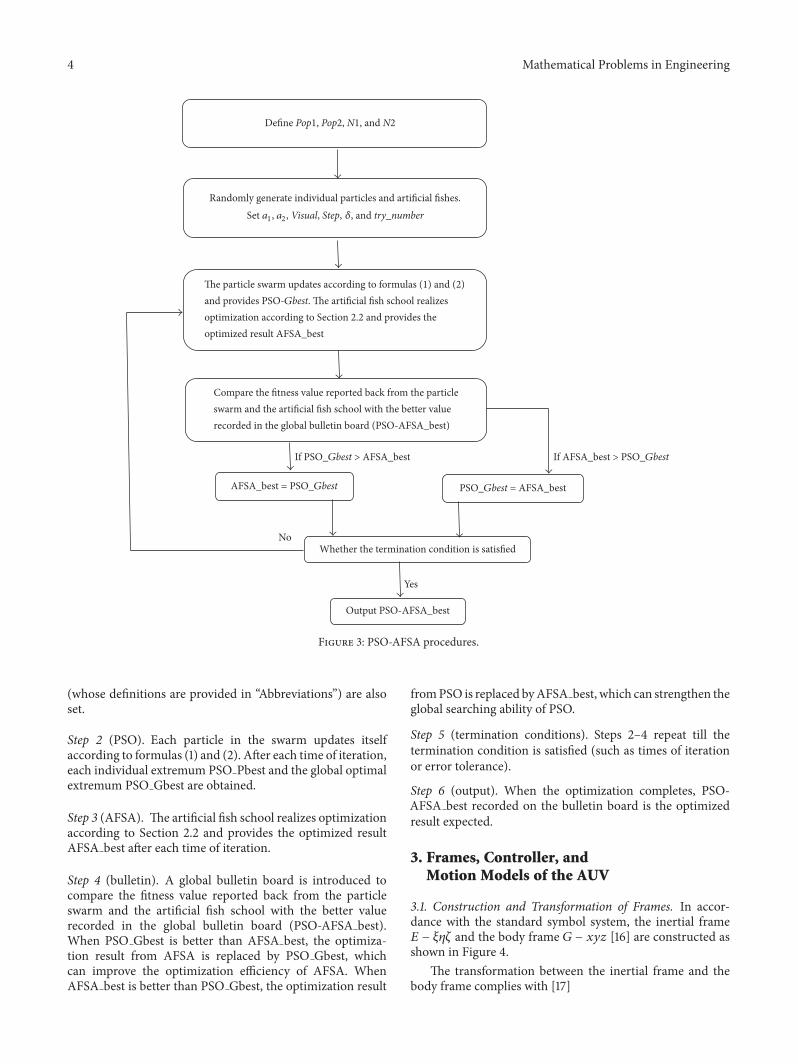
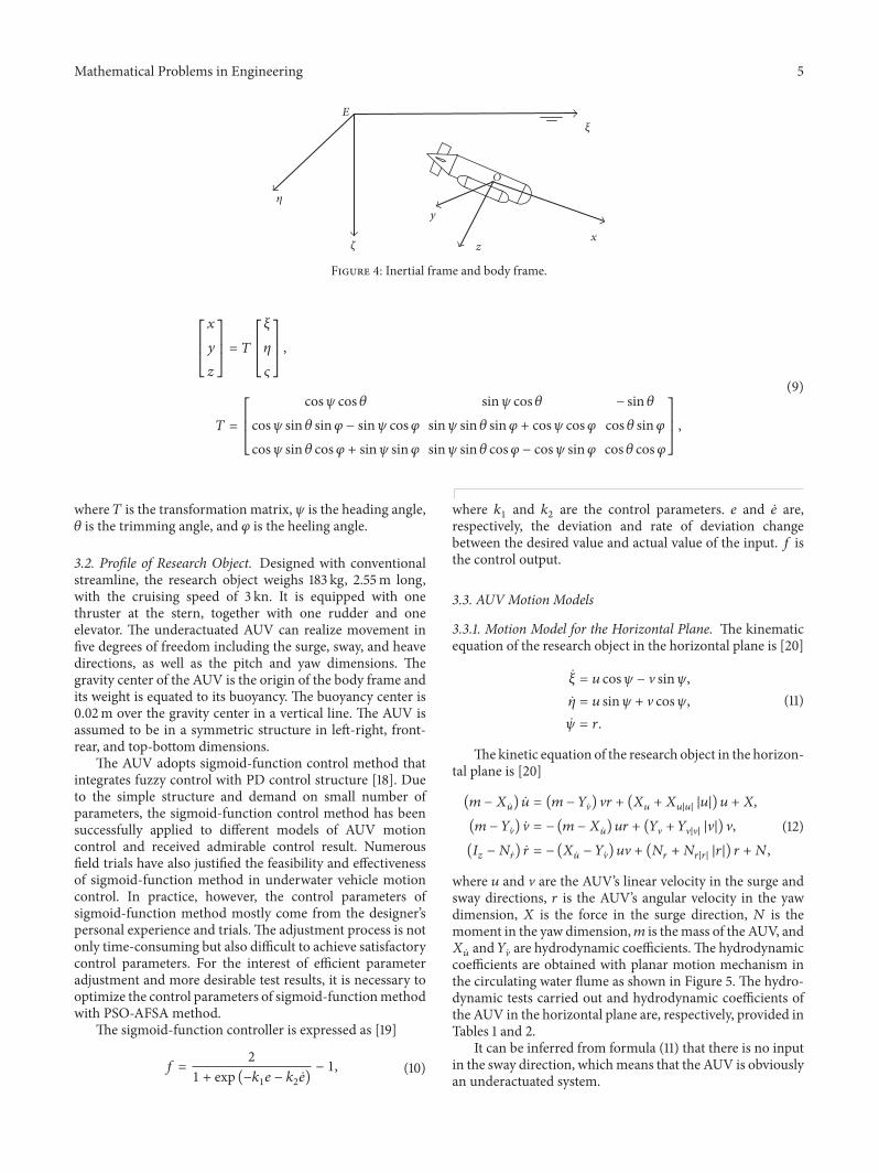
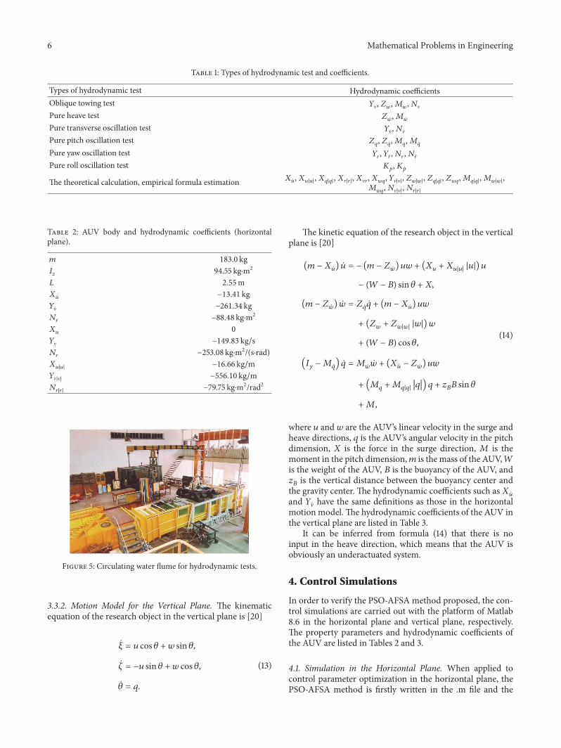
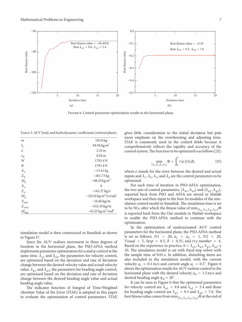
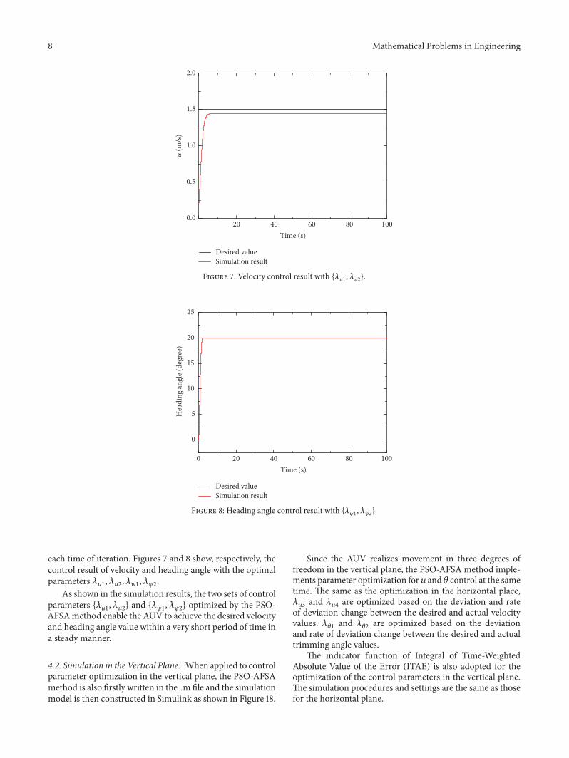
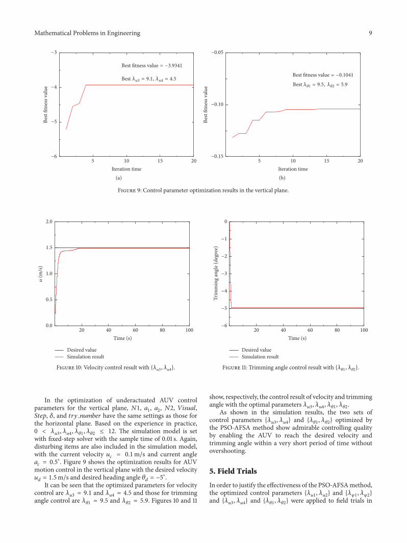
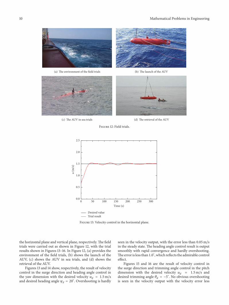
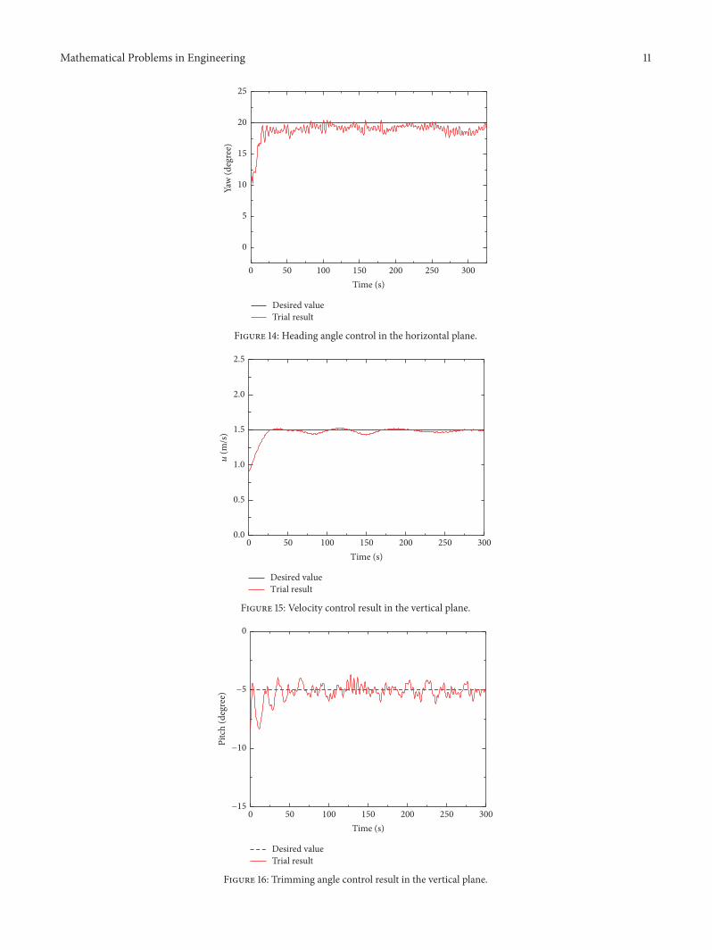
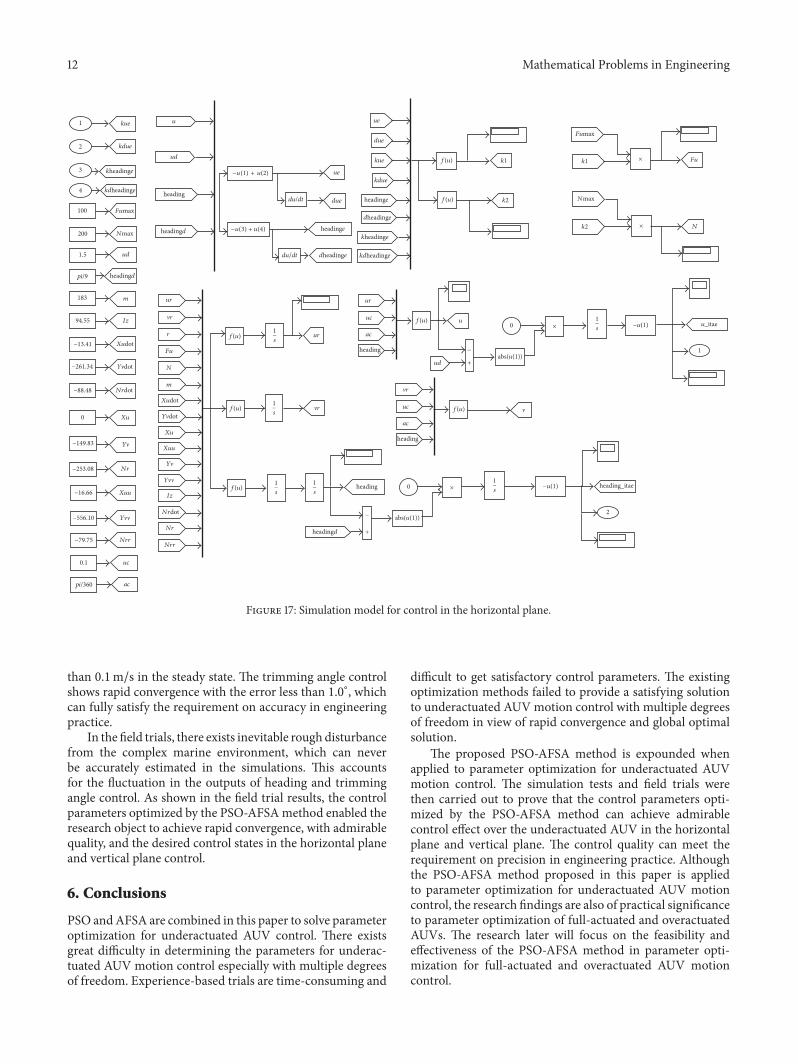
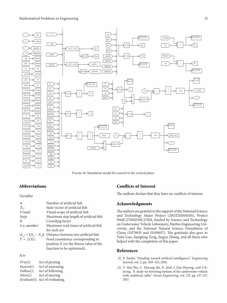