Embed Size (px)
Citation preview

An Architectural Space Program for the City of San AntonioPre-K 4 SA Early Childhood Centers - East and Westside Centers
Final - May 2013


An Architectural Space Program for the City of San Antonio
Pre-K 4 SA Early Childhood Centers - East and Westside Centers
FinalMay 2013


Foreword
Facility Programming and Consulting An Architectural Space Program for the City of San AntonioFinal - May 2013 Pre-K 4 SA Early Childhood Centers - East and Westside Centers Page I
F acility programming and Consulting (FPC) was engaged to prepare the architectural program of requirements for the Pre-K 4 SA Early Childhood Centers - East and Westside Centers for
the City of San Antonio. The architectural program is intended to give the design team a “workbook” from which to design that lists all of the require-ments for each space within the building. The architectural program is not intended to influence the creativity of the design team by advocating any design style or procedure. All diagrams and drawings contained herein are intended to illustrate the relationships involved, and are provided as an example to augment the text. The design team should not consider any of the diagrams as a design directive.
This architectural program document is structured as follows:
1. The Executive Summary contains a brief overview of the project. The chapter establishes the project’s objectives, overall project process and site location. It also acknowledges the people involved with the program.
2. Space and Adjacency Requirements deals with the space requirements and functional relationships portion of the program. It, along with the next chapter, comprise the majority of the document.
3. Technical Requirements deals with project requirements that affect the design of the building including architectural, structural, mechani-cal and electrical requirements, finishes and illuminations, fixtures furnishings and equipment lists required for the proper design and construction of the individual spaces listed in the space summaries of the previous chapter.
4. Code and Standards identifies the standards and constraints that will control the project design.
5. Site Studies is an analysis of the proposed project site.
6. Programming Estimate outlines the preliminary cost for the project.
7. Preliminary Project Schedule describes the factors that may affect the project schedule and outlines the preliminary timeline for comple-tion of the project.
8. Appendix chapter includes additional support and reference data relevant to this project.

Foreword
An Architectural Space Program for the City of San Antonio Facility Programming and ConsultingPre-K 4 SA Early Childhood Centers - East and Westside Centers Final - May 2013Page II
This document supersedes all previous publications. The contents of this document are not for regulatory approval, permitting, or construction.
Final - May 2013

Table of Contents
Facility Programming and Consulting An Architectural Space Program for the City of San AntonioFinal - May 2013 Pre-K 4 SA Early Childhood Centers - East and Westside Centers Page III
Chapter PageExecutive Summary ......................................................................................... 1.1
Space and Adjacency Requirements ............................................................2.1
Introduction .................................................................................................................................. 2.1
Symbols, Abbreviations, and Definitions...............................................................................2.2
Overview and Organization ..................................................................................................... 2.5
Non-Assignable Spaces .............................................................................................................2.15
Code and Standards ........................................................................................3.1
Technical Requirements ................................................................................ 4.1
Introduction ..................................................................................................................................4.1
Room Data Sheets: Instructional / Activity Space - Children ........................................4.3
Room Data Sheets: Administrative Space ..........................................................................4.13
Room Data Sheets: Professional Development Space .................................................... 4.27
Room Data Sheets: Building Support Functions ..............................................................4.33
Room Data Sheets: Exterior Areas - Children .................................................................4.43
Room Data Sheets: Non-Assignable Space .......................................................................4.47
Site Studies .......................................................................................................5.1
Programming Estimate .................................................................................. 6.1
Preliminary Project Schedule ........................................................................7.1
Appendix ...........................................................................................................8.1
Meeting Minutes ...........................................................................................................................A
SA2020 Brainpower Initiative Task Force..............................................................................B
City of San Antonio Standards for Office Space, Furniture and Equipment................. C
Synopsis of the Head Start Center Design Guidelines .......................................................D
Northside Independent School District Playground Development Guidelines ............. E
LEED Checklists ..........................................................................................................................F
Mold and Moisture Prevention References .............................................................................G
City Green Building Policy Ordinances ..................................................................................H
City of San Antonio Cabling Standards (ITSD) ..................................................................I

Table of Contents
An Architectural Space Program for the City of San Antonio Facility Programming and ConsultingPre-K 4 SA Early Childhood Centers - East and Westside Centers Final - May 2013Page IV

Acknowledgements
Facility Programming and Consulting An Architectural Space Program for the City of San AntonioFinal - May 2013 Pre-K 4 SA Early Childhood Centers - East and Westside Centers Page V
AcknowledgementsA significant commitment of time and effort was made by the following participants to create the program for the new Pre-K 4 SA Early Childhood Centers. Their participation is greatly appreciated.
City of San Antonio
City Manager’s OfficePeter Zanoni - Assistant City Manager
Rebecca Flores - Education Policy and Services Administrator
Pre-K 4 SAKathleen Bruck - Interim CEO
Sandy Chavarria - Center Director
Capital Improvements Management Services (CIMS)Mike Etienne - Assistant Director
Razi S. Hosseini - Assistant Director
William Hensley - Project Manager
Jeff Rodriguez - Project Control Manager
Department of Human Services - Head Start ProgramMelody Woosly
Jessica Dovalina
Rhonda Roach
Information Technology Services Department (ITSD)Mike Walker - Assistant Director, Infrastructure
Kevin Goodwin - Assistant Director, Applications
Mike Mitchell - Assistant Information Services Manager
Bart Mulcahy - Senior IT Manager
Northeast Independent School DistrictGarrett Sullivan - Executive Director, Construction Management and Engineering
Jorge Cabello - Senior Director - Construction Planning and Design

Acknowledgements
An Architectural Space Program for the City of San Antonio Facility Programming and ConsultingPre-K 4 SA Early Childhood Centers - East and Westside Centers Final - May 2013Page VI
Northside Independent School DistrictLeroy San Miguel - Assistant Superintendent, Facilities and Operations
Bill Peters - School Property Analyst, Facilities and Operations
Mike Boehmer - Project Manager, Engineering Services
Pat Mesquiti - Specialist, Pre-K and Kindergarten
San Antonio Independent School DistrictErin Burnett - Education Specialist
Christa Carreño - Coordinator
Facility Programming and ConsultingDoug Lowe, AIA
Bryan Sibille
Molly Cundari, AIA

1Executive Summary


Executive Summary
Facility Programming and Consulting An Architectural Space Program for the City of San AntonioFinal - May 2013 Pre-K 4 SA Early Childhood Centers - East and Westside Centers Page 1.1
Introduction
Facility Programming and Consulting (FPC) was engaged by the City of San Antonio (CoSA) to prepare an architectural program
of requirements for the Pre-K 4 SA Early Childhood Centers - East and Westside Centers.
This document is organized as follows:
1. Executive Summary
2. Space and Adjacency Requirements
3. Technical Requirements
4. Code and Standards
5. Site Studies
6. Programming Estimate
7. Preliminary Project Schedule
8. Appendix
Project Description and ScopeThe concept for the City of San Antonio Pre-K 4 SA Early Childhood Centers was presented in May 2012 by the SA2020 Brainpower Initiative Task Force. The committee was assembled in May 2011 by Mayor Julian Castro and consisted of local business and education leaders who were engaged to determine if improvements to San Antonio’s education out-come could be attained through targeted financial investment. Three areas of education were studied — very early childhood education, dropout prevention and college attainment. The group, which included area school superintendents and college presidents, was led by USAA CEO Maj. Gen. Joe Robles and H-E-B Chairman and CEO Charles Butt.
After one year of investigation and study, the committee determined that the greatest impact would be achieved if all investment was focused on early childhood education. Studies of best practices and evidence-based outcomes in other U.S. cities had shown that children who are prepared to learn when they enter kindergarten are more confident and apt to succeed throughout their academic career. According to the committee report, research at the University of Wisconsin found that an average of $6,730 invested in early education saved $47,759 by eliminating or reducing expenses associated with remediation, unemployment and incarceration. In addition, providing children with an early start on education provides teachers and administrators with the ability to write a curriculum for which all students are on the same level of preparedness.
Research found that, of the 20,000 four-year olds who reside in San Antonio today and are eligible for pre-K instruction, approximately 5,000

Executive Summary
An Architectural Space Program for the City of San Antonio Facility Programming and ConsultingPre-K 4 SA Early Childhood Centers - East and Westside Centers Final - May 2013Page 1.2
are under-served. To place San Antonio in a position to provide a glob-ally competitive and prepared workforce in the future, the Brainpower Initiative recommended the construction of multiple early childhood centers to reach this population which is currently falling through the gaps.
The initial plan proposed the construction of two Pre-K 4 SA Early Childhood Centers to be strategically located on the north and south side of San Antonio. Each center was designed to accommodate 500 students at maximum capacity with an initial capacity of 350 at the two initial centers. In subsequent years, two more new centers were proposed for the east and west side, allowing the program to serve an additional 800 children.
The Northside and Southside Centers are scheduled for completion and operation for the Fall 2013 school year. This program document is intended as a guideline for the construction of the two remaining centers to support the population residing in the east and west quadrants of San Antonio. Each center will be provided with the following basic components:
� Instructional area
� Administrative area for the personnel responsible for operating the Center
� Professional development space to be utilized for training of teach-ers throughout the city, as well as for outreach to parents within the community
� Building support functions, including a warming kitchen for catered meal delivery and prep, laundry and building maintenance
� Outdoor play area
The staff and personnel which will oversee the professional development component of all centers will continue to be housed at the Southside Center, as originally programmed. Additional administrative space, beyond that which is included in the program which follows, was not anticipated at the time of publication of this document.
Each of the proposed two new facilities will total approximately 48,314 gross square feet (gsf) and contain approximately 31,404 assignable square feet (asf). Sites for the facilities had not been identified at the time of publication of this report.

Executive Summary
Facility Programming and Consulting An Architectural Space Program for the City of San AntonioFinal - May 2013 Pre-K 4 SA Early Childhood Centers - East and Westside Centers Page 1.3
Project Vision and GoalsThe SA2020 Brainpower Initiative identified the following objectives for the proposed centers:
� Establish world-class early learning centers that model best practices
� Recruit highly qualified and innovative leaders to design and lead the model centers
� Utilize the centers as learning labs for ongoing professional develop-ment for teachers throughout the city, raising student achievement in existing pre-K classes by creating a highly capable pre-K workforce that consistently demonstrates effective teaching
� Focus on creating classrooms defined by strong reading (literacy) and math (numeracy) learning and development of lifelong learning skills
� Serve the city’s remaining pre-K eligible children who are currently falling through the gap
� Utilize Head Start programs as the initial model for development of the facilities and curriculum
� Educate parents in the importance of pre-K learning to their child’s later success in life (i.e. reduced absenteeism, transition to kindergarten) and engage them in supporting their child’s learning at home
� Implement the entire initiative, in phases, within five years
� Facilities
à Keep class size as close to 15 as possible (given resources); provide two instructors per classroom
à Organize classrooms in a “pod structure” of 4-5 pods of five class-rooms each
à In lieu of a cafeteria, serve meals in-classroom “family style” to facilitate teaching self-help skills, social skills and reinforcing learn-ing through informal conversation
à Incorporate child bathrooms and storage closets shared between two classrooms
During programming sessions with the steering committee, the follow-ing additional objectives were identified for the new Pre-K 4 SA Early Childhood Centers:
� Although classrooms will be designed to support the education of children with disabilities, children with severe disabilities will be served at other facilities which are more suitable in their design to accommodate their special needs

Executive Summary
An Architectural Space Program for the City of San Antonio Facility Programming and ConsultingPre-K 4 SA Early Childhood Centers - East and Westside Centers Final - May 2013Page 1.4
Preliminary Project CostAt the time of publication of this document, a total project budget for the construction and finish-out of both the Eastside and Westside centers was not available. It is the intention that the facilities will be constructed by a developer and leased to the City. The allocated budget will be utilized for tenant fit-out. The budget will continue to be reviewed regularly during the design and construction phases to determine necessary adjustments.
A 1/8-cent sales tax was approved by the citizens of San Antonio in November 2012. This sales tax increase has been proposed to generate an estimated $29 million annually towards the construction, operation and maintenance of the early childhood centers. The cost of this investment is estimated to be $7.79 annually per median San Antonio household. In addition, the facilities may be eligible to receive matching state pre-Kinder-garten dollars estimated at between $10 million and $11 million annually.
Project ScheduleThe schedule which follows is preliminary and will be adjusted as the project moves further through the design phase and as the construction drawings are developed. Items which may affect schedule include funding, permitting, construction document quality, contractor bids, contractor quality, and weather.
The Eastside and Westside Centers will be constructed by a developer then leased back to the City. Therefore, the schedule will be developer-driven with a substantial completion by July 2014.

Executive Summary
Facility Programming and Consulting An Architectural Space Program for the City of San AntonioFinal - May 2013 Pre-K 4 SA Early Childhood Centers - East and Westside Centers Page 1.5
Building Space Summary (Proposed)
City of San Antonio Pre-K 4 SA Projected Projected(Eastside and Westside Centers) ASF GSF*
Instructional / Activity Space - Children 22,950 35,308
Administrative Space 1,944 2,991Childcare Center Administration Suite 1,680 2,585Nurse Office 264 406
Professional Development Space 5,450 8,385
Building Support Functions 1,060 1,631
Total Building Project Size 31,404 48,314
Exterior Areas - Children 11,400 14,250Parking 70,000
Total Programmed Area Requirement(Building + Exterior Areas / Parking) (GSF) 132,564
*Calculated at net to gross ratio of 65% efficiency
Instructional Space, 73%
Administrative Space, 6%
Professional Development, 5%
Building Support Functions, 3%

Executive Summary
An Architectural Space Program for the City of San Antonio Facility Programming and ConsultingPre-K 4 SA Early Childhood Centers - East and Westside Centers Final - May 2013Page 1.6

2Space and Adjacency Requirements


Space and Adjacency Requirements
Facility Programming and Consulting An Architectural Space Program for the City of San AntonioFinal - May 2013 Pre-K 4 SA Early Childhood Centers - East and Westside Centers Page 2.1
Introduction
T his chapter deals with the space requirements and functional relationships portion of the program for the proposed Eastside and
Westside Pre-K 4 SA Early Childhood Centers.
The program for both facilities is the same. Each facility shall include instructional space related to early childhood education, outdoor play areas, administrative offices for the center operation and building support functions related to the program.
In addition, training classrooms for professional development and a library/family resource room for community outreach are included at each of these centers. Administrative offices which will oversee the Professional Development component of both centers will continue to be operated from the Southside Center currently under construction. Additional administrative need at the Eastside and Westside facilities was not anticipated at the time of publication of this report.
The building space summaries and diagrams which follow are intended to be applied to and included at each site. They are organized into the following general categories: Instructional / Activity Space for Children, Administrative Space, Professional Development Space, Building Support Functions, Exterior Areas and Parking.
A brief discussion of the Non-Assignable Spaces, including, but not limited to, janitors closets, telecommunications closets, and service/delivery areas, which have been identified for inclusion in both buildings, is located at the end of this chapter.
This chapter will serve as a checklist for the design team as they design and lay out the building(s). The chapter is organized into the following sections:
� Symbols, Abbreviations and Definitions
� Organization and Overview (by Individual Site)
à Building Organization
à Building Space Summary
à Building Stacking Diagram
à Adjacencies
� Non-Assignable Spaces
Detailed technical requirements for each individual space within the pro-posed building, including, but not limited to, architectural, mechanical, and electrical requirements, may be found in the chapter which follows.

Space and Adjacency Requirements
An Architectural Space Program for the City of San Antonio Facility Programming and ConsultingPre-K 4 SA Early Childhood Centers - East and Westside Centers Final - May 2013Page 2.2
Symbols
Walled Area
Designated Area (not walled)
Circulation Path
Main Entry
Strong Relationship Between Spaces(should be able to travel directly between areas)
Medium Relationship Between Spaces(should be nearby, but not necessarily directly adjacent)
Weak Relationship Between Spaces(can travel through other spaces or down hallways, but not necessary to travel directly between the spaces)
AbbreviationsMany terms used in this document have been abbreviated:
ada Americans with Disabilities Act
aff Above Finish Floor
asf Assignable Square Feet
cfci Contractor Furnished, Contractor Installed
cosa City of San Antonio
gfci Ground Fault Circuit Interrupter
gsf Gross Square Feet
hvac Heating, Ventilation and Air Conditioning
idf Intermediate Distribution Frame
itsd Information Technology Services Department
max / min Maximum / Minimum
mdf Main Distribution Frame
nasf Non-Assignable Square Feet
no Number
ofoi Owner Furnished, Owner Installed
ofci Owner Furnished, Contractor Installed
qty Quantity
vct Vinyl Composition Tile
Symbols, Abbreviations, and Definitions

Space and Adjacency Requirements
Facility Programming and Consulting An Architectural Space Program for the City of San AntonioFinal - May 2013 Pre-K 4 SA Early Childhood Centers - East and Westside Centers Page 2.3
DefinitionsListed below are definitions of frequently used terms in this chapter:
Assignable Square Feet (asf)
The usable area or area within the inside face of the interior walls of each space
Gross Square Feet (gsf) The area within the outside face of the exterior walls of the building which includes assignable square feet, non-assignable square feet, building service area, circulation area, mechanical area, and structural area
Intermediate Distribution Frame (IDF)
A controlled environment to house telecom-munications equipment and connecting hard-ware. An IDF interconnects and manages the telecommunications wiring between an MDF and workstation devices / equipment locations.
Main Distribution Frame (MDF)
The telecommunications demarcation point for all facility, backbone, riser and horizontal cabling. This is a controlled environment where private or public lines enter a building to pro-vide the internal network. Cables are typically routed through the centralized MDF to an IDF.
Non-Assignable Square Feet (nasf)
Areas such as mechanical space, telecommu-nication closets, janitor closets, etc., which are an inherent part of the building, but are not usable space for the owner’s program activi-ties (includes building service, circulation, and mechanical areas)
Structural Area The sum of all areas on all floors that can not be occupied or put to use because of structural building features
Technical Requirements Mechanical, electrical, and plumbing (mep) and other physical, technical, or building con-struction requirements
Symbols, Abbreviations, and Definitions

Space and Adjacency Requirements
An Architectural Space Program for the City of San Antonio Facility Programming and ConsultingPre-K 4 SA Early Childhood Centers - East and Westside Centers Final - May 2013Page 2.4
Assignable vs. Gross Square FeetThe tables and charts in this chapter depict area sizes in Assignable Square Feet (asf) and non-assignable square feet (nasf) unless Gross Square Feet (gsf) is specifically noted. Assignable square footage measures only the usable area of a given space. It does not include spaces such as lobbies, corridors (except for internal circulation within suites) and other public and support spaces such as mechanical rooms, toilets, etc. These types of spaces are included in the non-assignable square footage. The sum of the assignable square footage, the non-assignable square footage, and the structural areas is equal to the gross square footage of the building.
Note: Spaces listed individually as components of a space (ie. closets, food prep, restrooms, etc. which compose the instructional classroom) are noted in assignable square feet and do not include the required addi-tional space necessary to accommodate the wall thickness required which forms the perimeter/boundary of that individual space. Designer shall take note and ensure that each individual space is designed to meet the minimum asf as outlined in the space summaries which follow.
Internal CirculationIn addition to lobbies and mechanical rooms, the assignable-to-gross factor for the building will include space for major building corridors which pro-vide access to the major spaces in the facility. This space allocation does not include enough space for hallways and semi-public waiting or reception spaces which are affiliated with office suites. The suites themselves are accessed from the major building corridors, while the offices and other spaces within the suite are accessed from “internal circulation.” A factor for internal circulation has been included where applicable.
Symbols, Abbreviations, and Definitions

Space and Adjacency Requirements
Facility Programming and Consulting An Architectural Space Program for the City of San AntonioFinal - May 2013 Pre-K 4 SA Early Childhood Centers - East and Westside Centers Page 2.5
Building Organization
T he program for the new Pre-K 4 SA Early Childhood Center on the Eastside and Westside will be new construction and total
approximately 31,404 asf which translates to 48,314 gsf at an efficiency of 65 percent.
The program for each of the facilities will include instructional classrooms for early childhood education, outdoor play areas, administrative offices for the center operation and building support functions related to the program, including a kitchen, laundry and janitorial / facilities person-nel office. A library / family resource room for professional development and community outreach has been identified as an important component which should also be provided within this facility.
Similar to the programs for the Northside and Southside Centers under construction, each center will serve 500 children. Professional develop-ment activities, such as training and continuing education of instructors, will occur through site visits and activities in the classroom, as well as in one of three training rooms programmed at each of these facilities. These spaces will also be available for scheduled daytime and after-school cer-emonies and events (ie. convocation, awards ceremonies, etc.) centered around the children who attend the Pre-K 4 SA centers. Administrative offices which oversee the Professional Development programs at each of the centers will continue to be housed at the Southside Center.
In addition to the building interior areas, outdoor play areas will be required as part of the curriculum and to meet state licensing requirements. The play areas should be located adjacent to the indoor instructional areas and age-appropriate, providing a variety of playscapes to allow for the children to have different experiences.
Parking should be provided on-site for personnel and visitors. In addition, a short-term parking area or parent drop-off area should be incorporated into the design, where feasible.
Note: Center final design must provide instructional and outdoor activ-ity space which must meet the minimum requirements for licensing and regulation. Information on licensing and regulation standards and require-ments may be found in the chapter which follows.
Overview and Organization

Space and Adjacency Requirements
An Architectural Space Program for the City of San Antonio Facility Programming and ConsultingPre-K 4 SA Early Childhood Centers - East and Westside Centers Final - May 2013Page 2.6
City of San Antonio Pre-K 4 SA Projected Projected(Eastside and Westside Centers) ASF GSF*
Instructional / Activity Space - Children 22,950 35,308
Administrative Space 1,944 2,991Childcare Center Administration Suite 1,680 2,585Nurse Office 264 406
Professional Development Space 5,450 8,385
Building Support Functions 1,060 1,631
Total Building Project Size 31,404 48,314
Exterior Areas - Children 11,400 14,250Parking 70,000
Total Programmed Area Requirement(Building + Exterior Areas / Parking) (GSF) 132,564
*Calculated at net to gross ratio of 65% efficiency
Instructional Space, 73%
Administrative Space, 6%
Professional Development, 5%
Building Support Functions, 3%
Building Summary
Overview and Organization
Space and Adjacency Requirements
Facility Programming and Consulting An Architectural Space Program for the City of San AntonioFinal - May 2013 Pre-K 4 SA Early Childhood Centers - East and Westside Centers Page 2.7
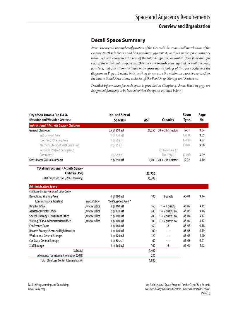
Detail Space Summary Note: The overall size and configuration of the General Classroom shall match those of the existing Northside facility and be a minimum 950 gsf. As outlined in the space summary below, 850 asf comprises the sum of the total assignable, or usable, clear floor area for each of the individual components. This does not include area required for wall thickness, structure, and other items included in the gross square footage of the space. Reference the diagram on Page 4.6 which indicates how to measure the minimum 720 asf required for the Instructional Area alone, exclusive of the Food Prep, Storage and Restroom.
Detailed information for each space is provided in Chapter 4. Areas listed in gray are designated functions to be located within the spaces outlined below.
City of San Antonio Pre-K 4 SA (Eastside and Westside Centers) ASF Capacity
Room Type
Page No.
Instructional / Activity Space - ChildrenGeneral Classroom 25 @ 850 asf 21,250 20 + 2 Instructors IS-01 4.04
Instructional Area 1 @ 720 asf IS-01A 4.05Food Prep / Staging Area 1 @ 50 asf IS-01B 4.07Teacher's Storage Closet (Walk-In) 1 @ 25 asf IS-01C 4.08Restroom (Shared Between (2) Classrooms) 1 @ 55 asf
1.5 Toilets ea. (3 Fixt. Total) IS-01D 4.09
Gross Motor Skills Classrooms 2 @ 850 asf 1,700 20 + 2 Instructors IS-02 4.10
Total Instructional / Activity Space - Children (ASF) 22,950
Total Proposed GSF (65% Efficiency) 35,308
Administrative SpaceChildcare Center Administration SuiteReception / Waiting Area 1 @ 100 asf 100 2 guests AS-01 4.14 Administrative Assistant workstationDirector Office private office 1 @ 160 asf 160 1 + 4 guests AS-02 4.15Assistant Director Office private office 2 @ 120 asf 240 1 + 2 guests ea. AS-03 4.16Speech Therapy / Consultant Office private office 2 @ 100 asf 200 1 + 2 guests ea. AS-04 4.17Visiting PK4SA Administration Office private office 1 @ 100 asf 100 1 + 2 guests ea. AS-04 4.17Conference Room 1 @ 160 asf 160 8 AS-05 4.18Records Storage (Secure) (High Density) 1 @ 100 asf 100 — AS-06 4.19Workroom / General Storage 1 @ 120 asf 120 — AS-07 4.20Car Seat / General Storage 1 @ 60 asf 60 — AS-08 4.21Staff Lounge 1 @ 160 asf 160 6 AS-09 4.22
Subtotal 1,400Allowance for Internal Circulation (20%) 280
Total Childcare Center Administration 1,680
No. and Size of Space(s)
*in Reception Area *
Overview and Organization

Space and Adjacency Requirements
An Architectural Space Program for the City of San Antonio Facility Programming and ConsultingPre-K 4 SA Early Childhood Centers - East and Westside Centers Final - May 2013Page 2.8
City of San Antonio Pre-K 4 SA (Eastside and Westside Centers) ASF Capacity
Room Type
Page No.
No. and Size of Space(s)
Nurse OfficeNurse Office / Medicine Storage private office 1 @ 100 asf 100 1 + 1 guest AS-10 4.23Sick / Isolation Area 1 @ 60 asf 60 1 AS-11 4.24Bathroom w/Shower (ADA) 1 @ 60 asf 60 — AS-12 4.25
Subtotal 220Allowance for Internal Circulation (20%) 44
Total Nurse Office 264
Total Administrative Space (ASF) 1,944Total Proposed GSF (65% Efficiency) 2,991
Professional Development SpaceTraining / Multipurpose Room 3 @ 1,500 asf 4,500 60 ea. PD-01 4.28Library / Family Resource Room (+Computer Area) 1 @ 850 asf 850 2 + 20 guests PD-02 4.30Table / Chair Storage 1 @ 100 asf 100 — PD-03 4.32
Total Professional Development Space (ASF) 5,450
Total Proposed GSF (65% Efficiency) 8,385
Building Support FunctionsLobby / Reception Area 1 @ 300 asf 300 Varies BS-01 4.34
Receptionist workstationCatered Meal Receiving and Staging 1 @ 400 asf 400 — BS-02 4.35
Warming / Prep Area 1 @ 250 asf BS-02A 4.36Walk-In Cooler 1 @ 50 asf BS-02B 4.37Pantry Area 1 @ 100 asf BS-02C 4.38
Laundry 1 @ 60 asf 60 — BS-03 4.39Janitor / Facilities Personnel and Building Storage 1 @ 200 asf 200 1 BS-04 4.40Classroom Supply / Bulk Materials Storage (High Density) 1 @ 100 asf 100 — BS-05 4.41
Total Support Functions (ASF) 1,060Total Proposed GSF (65% Efficiency) 1,631
Total Building Proposed ASF 31,404Total Building Proposed GSF 48,314
Exterior Areas - ChildrenOutdoor Play Area (4 Year Olds) 7 @ 1,600 asf 11,200 20 ea. EX-01 4.44Outdoor Storage 2 @ 100 asf 200 — EX-02 4.45
Total Exterior Areas (ASF) 11,400Total Proposed GSF (ASF+25%) 14,250
*in Reception Area *
Overview and Organization

Space and Adjacency Requirements
Facility Programming and Consulting An Architectural Space Program for the City of San AntonioFinal - May 2013 Pre-K 4 SA Early Childhood Centers - East and Westside Centers Page 2.9
Building Stacking DiagramDue to the age of the children served by this facility, it will be a state requirement that all children’s services be located on one continuous floor at ground level. A description of the adjacencies required between the functions to be located in the building, as outlined in the space sum-maries, are included on the pages which follow.
AdjacenciesThe new Eastside and Westside Pre-K 4 SA Early Childhood Center of Excellence will each include four distinct functions within the build-ing - instructional/activity space for the children, administrative space, professional development space and building support functions. On the building exterior, it is important that the center be provided a unique and distinguishing identity to indicate its location and function to the com-munity. Exterior playground space will also need to be provided. Building security will be of great importance due to the population served by the building. Public functions should be clearly segregated and zoned from those related to children’s activities and instruction.
Additionally, the designer may consider zoning the building with “like” functions into three general areas - public, instructional and administra-tive. The preferred adjacencies of Building Support Functions and Exterior Areas are discussed within each of the three zones, where applicable.
City of San Antonio Pre-K 4 SA (Eastside and Westside Centers) ASF Capacity
Room Type
Page No.
No. and Size of Space(s)
ParkingStaff / Administration / Visitor Parking* 200 @ 350 gsf 70,000 — — —
Staff / Administration Parking 80 @ 350 gsfVisitor / Drop-Off Parking 114 @ 350 gsfADA Parking 6 @ 350 gsf
Total Parking (GSF) 70,000
Total Programmed Area Requirement (Building + Exterior Areas / Parking)
(GSF) 132,564Total Minimum Acreage Required 3.04
*Minimum required parking requirement per UDC is 1 space per 375GSF. City has requested 200 parking spaces be provided.
Overview and Organization

Space and Adjacency Requirements
An Architectural Space Program for the City of San Antonio Facility Programming and ConsultingPre-K 4 SA Early Childhood Centers - East and Westside Centers Final - May 2013Page 2.10
Public AreasThe building should be organized around a central Lobby/Reception Area into which guests will be welcomed. This area will serve multiple purposes. In addition to an information station, its most important purpose will be to serve as a secure, controlled access point for anyone entering the facility. A staff member will be stationed in this space to direct guests to the appropriate office and receive parents who will come to check their children in or out of the center. The Administrative Space and Professional Development Space should also be immediately adjacent to and/or acces-sible from this space. Access to the Instruction/Activity Space for the Children will likely be through this security gate. All public activities should be segregated and configured in a way which will provide the greatest safety and security for the children.
The Childcare Center Administration Suite should be located directly adjacent to the Lobby/Reception Area to increase the visibility of the program to guests, as well as provide additional visual control of those entering and exiting the facility.
The Childcare Center Administration Suite should be located directly adjacent to the Lobby/Reception Area to increase the visibility of the program to guests, as well as provide additional visual control of those entering and exiting the facility. The Professional Development Space, which will provide a community outreach component, a library / family resource room, for use by the parents, educators and local community, should also be accessible from the Lobby area but may be located in a separate wing or corridor. Both the Childcare Center Administration and Professional Development spaces should be provided with an individual identity to assist visitors in wayfinding.
Instructional AreasInstructional Spaces should be accessible from the main building circula-tion and the Lobby/Reception Area. Access to the classroom area should be secure and controlled to provide the greatest security and safety of the children being served by the facility. General Classrooms should be dis-persed along the main circulation route and configured, ideally, in ‘pods’ of five. Where feasible, classrooms should be organized around and directly accessible to the fenced Outdoor Play Area where students will have the opportunity to experience a variety of playscapes. Inside the General Classrooms, area will be provided for instruction and open, accessible storage of children’s personal belongings, educational materials related to instruction and general storage of classroom supplies and instructor’s personal belongings. Each General Classroom will require a bathroom be accessible from the classroom. These facilities may be shared between classrooms. However, to meet the required ratio (1:17 children), this will require the construction of a bathroom with three fixtures to be located together and accessible from two separate classrooms. Similarly, two sinks
Pod Con�guration of Classrooms Around Outdoor Playground(Concept - Typical)
OutdoorPlaygroundGeneral
Classroom
GeneralClassroom
GeneralClassroom
GeneralClassroom
GeneralClassroom
Overview and Organization
Space and Adjacency Requirements
Facility Programming and Consulting An Architectural Space Program for the City of San AntonioFinal - May 2013 Pre-K 4 SA Early Childhood Centers - East and Westside Centers Page 2.11
will be required for each classroom for children’s handwashing. One sink will be located in the classroom while the second will be in the bathroom. A Food Prep / Staging Area will be located in each classroom to provide an area for catered meals, delivered from the Catered Meal Receiving and Staging area at multiple times throughout the day, to be stored and snacks prepared prior to distribution to the students.
In addition to the General Classrooms, two General Motor Skills Classrooms will provide indoor play and physical assessment/training area for the children.
Building Support Functions, such as the Catered Meal Receiving and Staging , Laundry and Janitor should also be located near the Instructional Areas and within the secure zone as these are the areas they will serve the most and personnel operating these functions will have passed the back-ground and security checks required for center staff. Meals will be catered and delivered to the Catered Meal Receiving and Staging Warming/Prep Area where they will be assembled on carts and distributed to the class-rooms throughout the day. A Loading /Delivery Service Area should be accessible from the Catered Meal Receiving and Staging to facilitate deliveries.
Administrative SpacesThe Childcare Center Administration should each be configured in a suite arrangement allowing for the Reception /Waiting Area to be accessed from the general building Lobby/Reception Area. This suite will contain the office of the Director and Assistant Directors, as well as space for outside consultants who may come in and work with the students, such as Speech Therapists or Counselors. An additional office has been provided, at each location, to be utilized by Pre-K 4 SA administrative staff, housed at the Southside Center, when visiting the centers. The Workroom / Staff Lounge will provide a space for the faculty and staff to relax, take a break and pre-pare materials for classroom instruction. Additional support functions will include a Conference Room for internal meetings, outside vendors and parent-teacher conferences, a secure Records Storage room, and General Storage for office materials and supplies. A Car Seat Storage room should be located in the office suite near the entry to allow for parents who share responsibility in dropping off/picking up the children to store the car seat for when the child is to be picked up. An alternate location would be to provide access to this space from the Receptionist located in the main building Lobby/Reception Area.
The Nurse’s Office should be located adjacent to the other administrative offices but with closer proximity to the children’s Instructional/Activity Space in order to limit the distance of travel from the classroom to the nurse with an ill child. This office will be located outside the secure zone so that parents may pick up their child. However, it should be located in a manner which will provide it visibility from the adjacent Childcare Center Administration suite.
Overview and Organization

Space and Adjacency Requirements
An Architectural Space Program for the City of San Antonio Facility Programming and ConsultingPre-K 4 SA Early Childhood Centers - East and Westside Centers Final - May 2013Page 2.12
Ideal Building ConfigurationsThe diagrams below indicate ideal configurations for the center which will support the pod concept for the classroom configuration around a playground area. These diagrams are for information purpose only and are in no way meant to direct the final design or building layout.
Adjacency Diagrams
Overall
Main Entrance(from Parking)
Lobby / Reception Area
ReceptionistMain Circulation
Secu
re /
Cont
rolle
d Acce
ss
BuildingSupport
Functions
Pod5
General Classrooms
Con�gure in Pods Around Outdoor Playgrounds (5 Classrooms per Pod - typ.) - See Detail Diagram
AdministrativeSpaces
Pod4
Pod3
Pod2
Pod1
ProfessionalDevelopment
Spaces
Gross MotorSkills
Classrooms
Overview and Organization

Space and Adjacency Requirements
Facility Programming and Consulting An Architectural Space Program for the City of San AntonioFinal - May 2013 Pre-K 4 SA Early Childhood Centers - East and Westside Centers Page 2.13
Detail Adjacency Diagram
Main
Entra
nce
(from
Park
ing)
Lobb
y / Re
cept
ion Ar
ea
Rece
ption
istM
ain Ci
rculat
ion
Secure / Controlled Access
Nurse
O�
ce /
Med
icine
St
orag
e
Nurse
O�
ce
Sick /
Iso
lation
Area
Bath
room
(ADA
)
War
ming
/Pr
ep Ar
ea
Cate
red M
eal R
eceiv
ing an
d Sta
ging
Exte
rior A
ccess
(Deli
verie
s)
Walk
-InCo
oler
Pant
ry
Janit
or /
Fac.
Perso
nnel
&Bl
dg.St
orag
e
Laun
dry
Exte
rior A
ccess
(to O
utdo
or Pl
aygr
ound
)
Instr
uctio
nal A
rea
Bath
room
Stor
age
Close
t
Food
Prep
Stag
ing Ar
ea
To Ad
jacen
t Clas
sroom
[Rat
io 1:1
7 - Re
com
men
dPla
cem
ent o
f (3)
Toile
tsto
be Sh
ared
betw
een C
lassro
oms]
Gene
ral C
lassro
oms
Con�
gure
in Po
ds Ar
ound
Out
door
Play
grou
nds (
5 pod
s of 5
Clas
sroom
s - ty
p.) -
See O
vera
ll Adja
cenc
y Diag
ram
x 25
Gros
s Mot
orSk
illsCla
ssroo
m (2
)
Traini
ng /
Mult
ipurp
ose
Room
(3)
Libra
ry /
Fam
ilyRe
sour
ce(+
Com
pute
r)
Prof
essio
nal D
evelo
pmen
t Spa
ce Dire
ctor’s
O�ce
Rece
ption
/W
aiting
Area
Adm
in.As
sista
nt
Conf
eren
ce/
Brie�
ng Ro
om
Assis
tant
Dire
ctor
O�ce
(2)
Reco
rds
Stor
age
(Sec
ure)
Gene
ral
Stor
age
Wor
kroom
/ St
a� Lo
unge
Child
care
Cent
er Ad
mini
strat
ion Su
ite
Car S
eat
Stor
age
Spee
ch Th
erap
y /Co
nsult
ant
O�ce
(2)
Vistin
g PK4
SAAd
mini
strat
ionO�
ce
Table
/ Ch
air St
orag
e
Classr
oom
Supp
ly/Bu
lk M
ater
ialSt
orag
e
Overview and Organization

Space and Adjacency Requirements
An Architectural Space Program for the City of San Antonio Facility Programming and ConsultingPre-K 4 SA Early Childhood Centers - East and Westside Centers Final - May 2013Page 2.14

Space and Adjacency Requirements
Facility Programming and Consulting An Architectural Space Program for the City of San AntonioFinal - May 2013 Pre-K 4 SA Early Childhood Centers - East and Westside Centers Page 2.15
Non-Assignable SpacesSeveral required functional spaces must be included in the building, though they are not considered “assignable”. These spaces include general circulation and lobby areas (including stairs and elevators), mechanical spaces, restrooms, utility/telephone/network closets and housekeeping closets, as well as any other infrastructure and support spaces which may result from the building’s design.
In addition to the assignable spaces described earlier in this chapter, the following non-assignable spaces shall be provided:
� Housekeeping/Custodial Closets
� Data/Telephone Closet
� Loading and Service
� IDF/MDF Rooms
� Public Restrooms
City of San Antonio Standards shall also be reviewed for detailed infor-mation concerning these spaces. Additional technical requirements may be found in Chapter 3.
Non-Assignable Spaces

Space and Adjacency Requirements
An Architectural Space Program for the City of San Antonio Facility Programming and ConsultingPre-K 4 SA Early Childhood Centers - East and Westside Centers Final - May 2013Page 2.16

3Code and Standards


Code and Standards
Facility Programming and Consulting An Architectural Space Program for the City of San AntonioFinal - May 2013 Pre-K 4 SA Early Childhood Centers - East and Westside Centers Page 3.1
Introduction
T he information which follows is to be applied to the building design and construction as a whole. In addition to applicable codes,
design and construction standards developed by the City of San Antonio shall also be referenced.
The chapter is organized into the following sections:
� Codes and Regulations
� City of San Antonio Standards
à Data Cabling Standards
à Office Space, Furniture and Equipment Standards
� State of Texas Regulations
à Texas Administrative Code
■ Department of Family and Protective Services - Minimum Standards for Child-Care Centers
à Texas Education Code
à Texas Health and Safety Code
� General Design Considerations
Detailed room-by-room requirements including technical requirements, finishes and illumination, and furnishings, fixtures, and equipment lists are included in the Technical Requirements chapter of this document.
Codes and RegulationsThe design team shall prepare a written code and standards analysis for the project. Assure all applicable codes are reviewed; where there is a discrepancy, the more stringent shall apply.
At minimum, the following codes and regulations, as adopted by the City of San Antonio at the time of publication of this report, shall apply:
� 2012 International Building Code (IBC)
� 2012 International Existing Building Code
� 2012 International Mechanical Code
� 2012 International Plumbing Code
� 2012 International Fuel Gas Code
� 2012 International Fire Code
� 2009 International Energy Conservation Code (IECC)
� 2011 National Electric Code
Local amendments to the codes outlined above, where applicable, shall also be consulted.

Code and Standards
An Architectural Space Program for the City of San Antonio Facility Programming and ConsultingPre-K 4 SA Early Childhood Centers - East and Westside Centers Final - May 2013Page 3.2
Other codes and regulations which will apply include:
� National Fire Protection Association (NFPA) Codes, with emphasis on NFPA 101 Life Safety Codes and including all referenced standards
� Texas Department of Licensing and Regulation, Elimination of Architectural Barriers Act
� Americans with Disabilities Act
� City of San Antonio Unified Development Code
� Texas Administrative Code
� Texas Education Code
� Sustainable Building Code
Other organizations with possible jurisdiction include:
� Texas Department of Family and Protective Services
� Environmental Protection Agency (EPA)
� Texas Commission on Environmental Quality (TCEQ)
� Occupational Safety and Health Administration (OSHA)
City of San Antonio Standards
Data Cabling Standards1. All data cable shall be installed per the City of San Antonio
“Cabling Standards” prepared by the Information Technology Services Department ( January 5, 2009; Revised December 21, 2011 - See Appendix of this document) and comply with the fol-lowing standards:
■ ANSI/NFPA 70-2005; National Electrical Code
■ ANSI/TIA 455-78-B-2002; Optical Fibres – Part 1-40: Measurement Methods and Test Procedures – Attenuation
■ ANSI/TIA 598-C-2005; Optical Fiber Cable Color Coding
■ ANSI/TIA 526-7-1998; Optical Power Loss Measurements Of Installed Single-mode Fiber Cable Plant
■ ANSI/TIA 526-14-A-1998; Optical Power Loss Measurements Of Installed Multimode Fiber Cable Plant
■ ANSI/TIA 568-B Series-2001; Commercial Building Telecommunications Cabling Standard
■ ANSI/TIA 606-A-2002; Administration Standard for the Telecommunications Infrastructure of Commercial Buildings
■ ANSI/J-STD 607-A-2002; Commercial Building Grounding (Earthing) and Bonding Requirements for Telecommunications

Code and Standards
Facility Programming and Consulting An Architectural Space Program for the City of San AntonioFinal - May 2013 Pre-K 4 SA Early Childhood Centers - East and Westside Centers Page 3.3
■ ANSI/TIA 569-B-2004; Commercial Building Standard for Telecommunications Pathways and Spaces
■ TIA/TSB 140-2004; Additional Guidelines for Field-Testing Length, Loss and Polarity of Optical Fiber Cabling Systems
2. Building shall be equipped with wireless technology and infrastructure.
3. The minimum dimensions for the MDF/IDF is 6’ x 8’ with a 9’ ceil-ing and a 36” door opening outward. This room will support up to 80 City Personnel. For buildings that house more than 80 people the minimum MDF/IDF size shall increase to 10’ x 10’with a 9’ ceiling and an outward swing 36” door. ITSD should be contacted during the design phase to determine final room layout.
4. On buildings requiring a MDF and one or more IDF’S the distance between rooms should be limited to 180 meters.
5. Provide a minimum (1) 2-port data and (1) telephone outlet at each modular workstation, unless noted otherwise.
6. Private offices shall be provided (2) 2-port data outlets and (1) telephone outlet on two perimeter walls, paying special attention to the possible location of furniture and equipment, unless noted otherwise.
7. General classrooms, conference rooms and other instructional or training areas shall include a minimum (2) 2-port data outlets in each classroom oriented in the front and back of each room.
8. Where ceiling mounted projectors are installed, provide power and data at ceiling for proper operation. Coordinate outlets with projector location.
Standards for Office Space, Furniture and EquipmentThe standards which follow were developed for traditional office buildings which are owned or leased by the City of San Antonio. While efforts to meet these standards as part of this project are recommended, they are included here for informational purposes only. A copy of the standards may be found in the Appendix of this document. As specified in the City of San Antonio Administrative Directive No. 1.10, “Standards for Office space, Furniture and Equipment, March 2003:”
1. Large, open work areas shall be furnished with systems furniture consisting of integrated workstations with shared, prefabricated walls
2. Traditional offices shall be furnished with modular furniture which may be used as either integrated workstations or freestanding furniture

Code and Standards
An Architectural Space Program for the City of San Antonio Facility Programming and ConsultingPre-K 4 SA Early Childhood Centers - East and Westside Centers Final - May 2013Page 3.4
3. Furniture material and features shall be as outlined in the standards
In addition to specifying furniture and equipment, the standards also propose a square foot guideline for the amount of office space as deter-mined by position level. This range has been used to develop the office and workstation types used throughout the space summaries. Office space guidelines are as follows:
� Executive: 200 to 250 ASF
� Management: 120 to 150 ASF
� Professional: 64 to 84 ASF
� Support: 48 to 64 ASF
Per City directive, 60% of office space shall be in open modular worksta-tions rather than private, enclosed offices. Diagrams of possible office /workstation configuration are included on the individual room data sheets which follow for informational purpose only.
All furniture shall comply with the Americans with Disabilities Act and all current applicable codes.
State of Texas Regulations
Texas Administrative Code
Department of Family and Protective Services - Minimum Standards for Child - Care Centers (Title 40, Part 19, Chapters 745 and 746)
As the Pre-K 4 SA project will be established independent of a public school district or charter school, it will be considered subject to the mini-mum regulations of a licensed child-care center as outlined in Chapters 745 and 746 of the Texas Administrative Code (TAC).
According to the TAC, a child-care center is defined as a facility that is licensed to care for seven or more children for less than 24 hours per day, at a location other than the permit holder’s home (§746.107). Pre-kindergarten age children are considered three and four years of age (§745.101). A caregiver is an employee counted in the child/caregiver ratio whose duties include direct care, supervision, guidance and the protection of children in care (§746.1101). An employee is any person employed by the child-care center, including caregivers; kitchen, office or maintenance personnel; other child-care center personnel; and the child-care center director (§746.1101).
The following requirements related to licensed child-care centers have been extracted from the minimum standard rules, Chapter 746, “Minimum Standards for Child-Care Centers,” as designated by the Texas Department of Family and Protective Services Licensing Division (December 2010;

Code and Standards
Facility Programming and Consulting An Architectural Space Program for the City of San AntonioFinal - May 2013 Pre-K 4 SA Early Childhood Centers - East and Westside Centers Page 3.5
Revised December 2012). The complete guidelines may be found at www.dfps.state.tx.us.
1. Child/caregiver ratio is based on the specified age of the children in the caregiver’s group. The classroom ratio which one caregiver may supervise for children aged 4 years old is 18 children, maxi-mum (§746.1601). For this project, the caregiver to child ratio is anticipated at 1 to 10.
2. The maximum number of children two or more caregivers may supervise is limited by the maximum group size. For children aged 4 years old, the maximum group size is 35 (§746.1609). For this project, the maximum group size is intended to be 20 children per classroom.
3. Caregivers must provide planned activities designed to meet the individual needs and developmental level of each child (§746.2201). Activities for pre-K age children must include the following (§746.207):
■ Daily morning and afternoon opportunities for outdoor play
■ Thinking skill and sensory development via age appropriate equipment or activities, including sand/water play, blocks, framed puzzles, simple board games, etc.
■ Small muscle development through activities such as coloring (crayon, marker, paint), collage materials, workbench and acces-sories, music and videos, rhythm instruments.
■ Large muscle development through interaction with small wagons, light-weight balls of all sizes, tricycles, push toys, swings, slides, outdoor building materials, etc.
■ Active play both indoors and outdoors including active games such as tag, dancing, dramatic or imaginary play that encourages running, stretching, climbing, walking and marching.
■ Language development through story-time, puppets, writing materials, books-on-tape, etc.
■ Social and emotional development via activities such as dress-up, dolls, transportation toys, play animals, table games, etc.
■ Development of self-help skills such as toileting, hand-washing, returning equipment to storage areas or containers, and serving and feeding.
■ Regular meal and snack times.
■ Supervised naptimes.
4. Pre-kindergarten age children are required to be provided physical space with furnishings and activities which do not limit children’s movement and space in which children are allowed to find or create

Code and Standards
An Architectural Space Program for the City of San Antonio Facility Programming and ConsultingPre-K 4 SA Early Childhood Centers - East and Westside Centers Final - May 2013Page 3.6
individual activities, while allowing the caregiver easy supervision (§746.2603).
5. Furnishing and equipment for pre-kindergarten age children must include at least the following (§746.2605):
■ Interest centers, such as dramatic play, block building, stories and books, science and nature activities, art and music activities, sensory and problem-solving activities. These interest centers must be clearly defined, organized for independent use by chil-dren and arranged so the children’s activities are visible to the caregiver.
■ Age-appropriate seating, tables and nap or rest equipment.
■ Enough popular items available so that children are not forced to compete for them.
■ Containers or low shelving available so items children can safely use without direct supervision are accessible to children.
6. Supervised sleep or rest period after the noon meal must be pro-vided for all children who are in care for five or more consecutive hours (§746.2901). Napping equipment must be arranged in a manner which does not block entrances/exits, interfere with chil-dren’s activity areas, limit the circulation path or does not allow for the caregiver to adequately supervise all children in the group (§746.2909). The room is allowed to be darkened as long as adequate lighting is provided to allow for visual supervision of the children at all times (§746.2911).
7. All children must be served regular meals and morning and after-noon snacks (§746.3301). Children in care for four to seven hours are to be provided either one meal or one meal and one snack, equal to 1/3 of their daily food needs (§746.3303). All food and drinks must be of safe quality and must be stored, prepared, distributed and served under sanitary and safe conditions, including, but not limited to the following (§746.3316):
■ Sanitize food service equipment, dishes and utensils after each use.
■ If no facilities existing for sanitizing dishes and utensils, provide only disposable, single-use items.
■ Wash re-usable napkins, bibs and tablecloths after every use.
■ Discard single-service napkins, bibs, dishes and utensils after use.
■ Serve children’s food on plates,napkins or other sanitary hold-ers. No food shall be placed on a bare table or eating surface, including the floor.
■ All food stored in the refrigerator must be covered.
Code and Standards
Facility Programming and Consulting An Architectural Space Program for the City of San AntonioFinal - May 2013 Pre-K 4 SA Early Childhood Centers - East and Westside Centers Page 3.7
■ Food prep areas must be separated from the eating, play and bathroom areas. The food prep area may not be utilized as a passageway while food is being prepared.
■ Poisonous or toxic materials, such as cleaning supplies, may not be stored with food.
8. Although it is not a requirement, it is the intention that the new facility will serve individual pre-prepared meals in a communal, family style, setting in each classroom. Caregivers must supervise children to prevent cross-contamination of the food (§746.3319).
9. Building, grounds and equipment must be cleaned, repaired and maintained to protect the health of the children. This includes, but is not limited to:
■ Machine wash cloth toys and linens.
■ Make all garbage inaccessible to children both indoors and outdoors. Dispose of all trash according to local and state requirements.
■ Only lead-free paints will be used.
■ All parts of the center utilized by children will be well heated, lighted and ventilated.
10. Children and employees are required to practice good health and safety practice through hand-washing before and after activities as outlined in the standards. Hands shall be washed with soap and running water. Pre-moistened towlettes or wipes and waterless hand cleaners are not acceptable substitutes (§746.3419).
11. A thermostat must control the water temperature at sinks and water accessible to children so that it may be no higher than 120 degrees Fahrenheit (§746.3423).
12. Disposable gloves shall be worn by caregivers when handling bodily fluids (§746.3425).
13. A Nurse’s Office, though not required, has been included in the program to allow for the care and supervision of an ill child until a parent is able to be contacted to pick up the child, as regulated by the minimum standards (§746.3605).
14. All areas accessible to children must be free from hazards, including but not limited to (§746.3701):
■ Electrical outlets must have childproof covers or safety outlets.
■ 220-volt electrical connections within a child’s reach must be covered with a screen or guard.
Code and Standards
An Architectural Space Program for the City of San Antonio Facility Programming and ConsultingPre-K 4 SA Early Childhood Centers - East and Westside Centers Final - May 2013Page 3.8
■ Air conditioners, electric fans and heaters must be mounted out of all children’s reach or have safeguards that keep any child from being injured.
■ Glass in sliding doors must be clearly marked with decals or other materials placed at children’s eye level.
■ Play materials and equipment must be safe and free from sharp or rough edges and toxic paints.
■ Poisonous or potentially harmful plants must be inaccessible to children.
■ All storage chests, boxes, trunks or similar items with hinged lids must be equipped with a lid support designed to hold the lid open in any position, be equipped with ventilation holes and must not have a latch that might close and trap a child inside.
■ All bodies of water (ie. pools, hot tubs, ponds, creeks, bird-baths, fountains, buckets, rain barrels) must be inaccessible to all children.
15. Although permissible, it is not required to have a video or audio monitoring system (§746.3705). Closed circuit video surveillance is desired at all building entries, outdoor play areas and in inte-rior hallways and corridors. Video feed will be stored on digital video recorders and servers housed in the building MDF/IDF room. Quantity and location of servers to be directed by ITSD. All recorded footage shall be capable of being accessed remotely by ITSD or other authorized individual(s).
16. Medication to be administered to children is to be stored out of the reach of children or in locked storage, in a manner which does not contaminate food and refrigerated, if required, separately from food (§746.3807). As a Nurse’s Office has been provided as part of this program, it is intended that any children’s medication will be stored in this location and administered by this individual. Records of administered medication must be maintained for at least three months (§746.3805).
17. One first-aid kit must be available in each building at the child-care center, stored in an easily accessible and designated area, known to all employees, which is out of the reach of children (§746.4001).
18. Children may only be released to a parent or a person designated by the parent (§746.4101). The child-care facility will be responsible for developing policies regarding the release of children, including the verification of identity of authorized individuals. Policies must include a reasonable means to record the identity of the individual, such as a copy of a valid photo identification, instant photograph of the individual, or recording of the driver’s license and car tag

Code and Standards
Facility Programming and Consulting An Architectural Space Program for the City of San AntonioFinal - May 2013 Pre-K 4 SA Early Childhood Centers - East and Westside Centers Page 3.9
numbers. Information must be retained in the child’s records for at least three months (§746.4103).
■ Consider utilization of a visitor management/registration system (ie. Raptor Security System or similar) to protect the students, faculty, and visitors at schools. Such systems enhance school security by reading visitor driver’s licenses, comparing information to a sex offender database, alerting campus adminis-trators if a match is found, then (assuming no match was made) printing a visitor badge, which includes a photo.
19. At least 30 square feet of indoor activity space must be provided for each child that the center is licensed to serve (§746.201). Indoor activity space is measured from the interior walls of the space at the floor level and excludes floor space occupied by permanent and stationary fixtures (ie. bookcases, shelving and storage/counter space) which are not intended for use by the children (§746.4213). Note, it is the intent that the new Pre-K 4 SA Centers provide the minimum 36 square feet per child as required by the Texas Education Code to allow for future flexibility of the center to contract with the local independent school districts to provide Pre-K services.
20. Children may not be cared for on any level above or below ground level without written approval from the state or local fire marshal (§746.4217).
21. 80 square feet of outdoor activity space must be provided for each child using the outdoor activity area at one time. At a minimum, the center must provide enough outdoor space to accommodate 25 percent of the licensed indoor capacity (§746.4301). It is the inten-tion that each Pre-K 4 SA Center will be licensed to accommodate 500 children at maximum capacity. In order to meet the licensing requirement, outdoor activity space to accommodate 125 children must be provided, at minimum. Exception: Northside Center is currently programmed to accommodate 360 children. This will require outdoor activity space to accommodate 90 children.
22. The User has requested a minimum fence six feet in height be utilized around outdoor activity space. Per regulation, a fence or wall at least four feet high must enclose the outdoor activity space (§746.4305). Each fenced yard must have at least two exits. An entrance to the building may count as one exit, but one exit must be away from the building (§746.4307).
23. Outdoor activity space must be accessible by a safe route, but is not required to be connected to the child-care center (§746.4311). Use of an outdoor activity space that is not connected to the child-care center, such as a nearby park, schoolyard, rooftop or other alternative, will required submission to and approval by the Texas Department of Family and Protective Services.

Code and Standards
An Architectural Space Program for the City of San Antonio Facility Programming and ConsultingPre-K 4 SA Early Childhood Centers - East and Westside Centers Final - May 2013Page 3.10
24. One hand-washing sink shall be provided for every 17 children (§746.4401). Sinks shall be located inside the child-care center and must be equipped with soap, running water and single-use dispos-able towels or hot-air hand dryers (§746.4405).
25. One flush toilet shall be provided for every 17 children (§746.4407). Toilets must be located inside the child-care center and must be designed to be able to be safely and independently accessed by the children, allowing supervision by caregivers, as needed (§746.4409). Although urinals may be counted in the ratio of children to toilets, it is the User’s desire that only flush toilets be provided in the pro-posed centers.
26. It is not necessary to provide toilets, sinks and fountains that are child-sized. However, if fixtures are used which are too high for children to use safely and independently, it is required to equip them with anchored steps and/or broad-based platform with a non-slip surface (§746.4419).
27. An individual cot, bed or mat that is waterproof or washable and labeled for each child must be provided to sleep or rest on (§746.4503). Floor mats used for napping must be marked or colored so that the sleeping side can be distinguished from the floor side.
28. Individual lockers, cubicles, separate hooks and shelves, or other adequate storage space must be provided for each child’s personal belongings (§746.4505).
29. Indoor and outdoor active play equipment at the child-care center must meet the following minimum safety requirements (§746.4601):
■ Equipment must be arranged so that caregivers may adequately supervise children at all times.
■ Design, scale and location of equipment must be appropriate for the body size and ability of the child using the equipment.
■ Equipment must not have openings or angles that can entrap a child’s body or body part that has penetrated the opening.
■ Equipment must not have protrusions or openings that can entangle something around a child’s neck or clothing.
■ Equipment must be securely anchored according to manufac-turer’s specifications to prevent collapsing, tipping, sliding, moving or overturning.
■ All anchoring devices must be placed below the level of the playing surface to prevent tripping or injury resulting from a fall.
■ Equipment must not have exposed pinch, crush or shear points on or underneath it.

Code and Standards
Facility Programming and Consulting An Architectural Space Program for the City of San AntonioFinal - May 2013 Pre-K 4 SA Early Childhood Centers - East and Westside Centers Page 3.11
■ Climbing equipment, swings or inflatables must not be installed over asphalt or concrete unless the asphalt or concrete is covered with properly installed unitary surfacing materials as specified in this title.
■ Porches or platforms more than 20 inches in height must be equipped with protective barriers that surround the elevated surface ,except for entrances and exits, and that prevent children from crawling over or through the barrier.
■ Stairs and steps on climbing equipment, regardless of height, must have handrails the children can reach. Rung ladders do not require handrails.
30. Children must not use the following types of equipment at the child-care center (§746.4603):
■ Heavy swings made of metal or that have metal components, such as animal figure swings.
■ Equipment that allows children to fall inside the structure and onto other parts of the structure, such as certain styles of monkey bars or jungle gyms.
■ Trampolines, except those less than four feet in diameter that are no higher than 12 inches above a properly installed and maintained resilient surface.
■ Swinging exercise rings and trapeze bars on long chains or free swinging ropes.
■ Multiple occupancy swings, such as teeter-totters, gliders, or chair swings (other than tire swings).
■ Swinging gates and giant strides.
31. In addition, children under five years of age must not be allowed to use the following types of equipment (§746.4605):
■ Free-standing arch climbers
■ Free-standing climbing pieces with flexible parts
■ Fulcrum seesaws
■ Log rolls
■ Spiral slides with more than one 360 degree turn
■ Track rides
32. The maximum height of the highest designated play surface on active play space shall not exceed five feet for equipment designed to be used by children younger than five (§746.4607).
33. All swing set seats shall be constructed of durable, lightweight rubber or plastic material. Edges of seats must be smooth or rounded and

Code and Standards
An Architectural Space Program for the City of San Antonio Facility Programming and ConsultingPre-K 4 SA Early Childhood Centers - East and Westside Centers Final - May 2013Page 3.12
have no protrusions. Swings must not be attached to a composite play structure (§746.4701).
34. Where utilized, tire swings must (§746.4705):
■ Not be made from heavy truck tires or tires with exposed steel-belted radials;
■ Not be suspended from a composite structure or with other swings in the same bay;
■ Have drainage holes drilled in the underside of the tire and maintained to facilitate water drainage; and
■ Have a minimum clearance between the seating surface of the tire swing and the uprights of the supporting structure of 30 inches or more when the tire is in a position closest to the support structure.
35. A ‘use zone’ is the surface area under and around a piece of equip-ment onto which a child falling from or exiting the equipment would be expected to land. Other than the equipment itself, the use zone must be free of obstacles that a child could run into or fall on top of and be injured (§746.4801).
36. The use zone for stationary equipment, excluding slides and soft contained play equipment, must extend a minimum of six feet in all directions from the perimeter of the equipment. Use zones for stationary equipment must not overlap other use zones (§746.4803).
37. Measurements for use zones for slides (§746.4805), to-fro swings (§746.4807), tire swings (§746.4809) and rotating or rocking equip-ment (§746.4813) shall conform to those requirements outlined in each section of the minimum standards.
38. Loose-fill surfacing material or unitary surfacing material shall be provided in the use zones for all climbing, rocking, rotating, bouncing or moving equipment, slides and swings (§746.4901). The height of the highest designated play surface on the equipment will determine the depth of the loose materials or the attenuation rating (thickness) of the unitary materials.
39. Acceptable loose-fill materials include, but are not limited to, loose particles such as sand, pea gravel, shredded wood products and shredded rubber (§746.4905).
40. Loose-fill surfacing materials must be installed and maintained to a depth of at least six inches when height of highest designated play surface is five feet or less (§746.4907). Loose-fill surfacing material are for exterior use only and must not be installed over concrete or asphalt. All equipment support posts shall be marked to indicate the depth at which the loose-fill surfacing material must be maintained under equipment.

Code and Standards
Facility Programming and Consulting An Architectural Space Program for the City of San AntonioFinal - May 2013 Pre-K 4 SA Early Childhood Centers - East and Westside Centers Page 3.13
41. Unitary surfacing materials are manufactured materials including rubber tiles, mats or poured-in-place materials cured to for a unitary shock-absorbing surface (§746.4909). If unitary surfacing materials are utilized, they must be installed and maintained according to manufacturer’s specifications; they may be installed over concrete or asphalt only if recommended by the manufacturer (§746.4913).
42. If indoor-climbing equipment or platforms over 20 inches in height are utilized in the classroom, floor surfaces must have a unitary shock-absorbing surface that will effectively cushion the fall of a child (§746.4915). Surface must be installed in the use zone accord-ing to manufacturer’s specifications. Carpet alone, even installed over thick padding, is not an acceptable resilient surface.
43. At the time of publication of this report, soft-contained play equip-ment and inflatable play equipment were not intended for installa-tion at the centers. Should the client determine this type of activity equipment is desired, designer shall refer to safety requirements, as outlined in the minimum standards, for soft play equipment (§746.4951, 4953 and 4955) and inflatables (§746.4971).
44. In case of emergency, the minimum standards require that the child-care center be designed with at least two exits to the outside that are located in distant parts of the building (§746.5209). Windows may be designated as a fire exit only if all children and caregivers are physically able to exit through the window to the ground outside safely and quickly.
■ Actual egress requirements will be determined by local building code requirements based on building occupancy and construc-tion type. Where there is a discrepancy between the code and the minimum standards, the more stringent shall apply.
45. Each classroom must have a source of emergency lighting that is approved by the state or local fire marshal, or battery-powered lighting, in case of electrical failure (§746.5211).
46. The child-care center must be provided with a fire extinguishing system, via sprinkler system and/or fire extinguishers (§746.5301). At a minimum, at least one fire extinguisher rated 3A-40BC must be provided in the child-care center (§746.5303). Extinguisher must be wall-mounted at a height where the top is no higher than five feet above the floor and is at least four inches above the floor or any other surface (§746.5305).
■ Actual sprinkler requirements will be determined by local build-ing code requirements based on building occupancy and con-struction type. Where there is a discrepancy between the code and the minimum standards, the more stringent shall apply.

Code and Standards
An Architectural Space Program for the City of San Antonio Facility Programming and ConsultingPre-K 4 SA Early Childhood Centers - East and Westside Centers Final - May 2013Page 3.14
47. A working smoke-detection system, approved by the state or local fire marshal, must be installed in the child-care center (§746.5313). This system may be an electronic alarm and smoke-detection system, or individual electric or batter-operated smoke detectors located in each room use by children, or both (§746.5311).
48. Each child-care center must be equipped with a working carbon monoxide detection system (§746.5531). System must be individual electric (plug-in or hardwire) or battery-operated carbon monox-ide detectors that is UL-listed OR an electronic carbon monoxide detection system connected to an electronic alarm/smoke detection system that is UL-listed (§746.5533).
■ If an electric or batter-operated detector is utilized, at least one must be installed on every level of each building in the child-care operation and must be installed in compliance with the state or local fire marshal’s instructions (§746.5535).
■ If an electronic detection system connected to an alarm/smoke detection system is utilized, the system must be installed accord-ing to the state or local fire marshal’s instructions (§746.5535).
49. It is not a requirement that the child-care center provide transporta-tion to/from the facility. However, should the user decide to pursue this route, transportation is required to be licensed and regulated as per the minimum standards, Subchapter X, ‘Transportation,” Section 746.5601 through 746.5621.
Texas Education CodeThe Texas Education Code (TEC), as established by the Texas Legislature, is a set of the state laws which govern public education in Texas. All edu-cational institutions supported in part or whole by state tax funds are required to meet these statues, unless specifically excluded by the code.
As it is neither a public, independent school district (ISD) or charter school, the Pre-K 4 SA project is not required to meet the requirements of the TEC. According to the TEC (Title 2, Chp.29, Subchapter E, Sec.29.1532), should the local school districts decide to contract with the Pre-K 4 SA child-care centers to provide pre-kindergarten services to their students, the program must, at a minimum, comply with the applicable child-care licensing standards adopted by the Department of Family and Protective Services under Chapter 42, Section 42.042, Texas Human Resources Code (September 2011). These minimum standards which the child-care center must meet have been outlined in the previous section.
Although it is not required to meet the TEC requirements for a pre-kinder-garten facility, according to discussions with the Texas Education Agency (TEA), should the City decide to offer space to public school children at its facilities, it is required the proposed Pre-K 4 SA Centers provide the minimum 36 square foot per child indoor activity area required by

Code and Standards
Facility Programming and Consulting An Architectural Space Program for the City of San AntonioFinal - May 2013 Pre-K 4 SA Early Childhood Centers - East and Westside Centers Page 3.15
the Texas Administrative Code (Title 19, Part 2, Chpt 61, Subchpt. CC, Rule 61.1036). According to the rule, pre-kindergarten classrooms, con-structed on or after January 1, 2004, shall have a minimum of 800 square feet per room or a minimum of 36 square feet per student. Meeting this requirement will also make the centers eligible for Head Start facility requirements (Reference Appendix for synopsis of Head Start Center Design Guidelines).
The information which follows has been extracted from the TEC as it pertains to items which affect the building or site design of a traditional public school Pre-K classroom. This information is provided here for refer-ence purpose only to compare and contrast the requirements of a public facility to that of the licensed child-care center. The designer may wish to incorporate some of these elements into the center design.
1. Provide flagpole(s) from which the United States and Texas flags may be flown on all regular school days (Title 1, Chp. 1, Sec.1.003).
2. Each school district must employ a sufficient number of teachers certified under Subchapter B, Chapter 21, to maintain an average ratio of not less than one teacher for each 20 students in average daily attendance (Title 2, Chp. 2, Subtitle E, Chp. 25, Sec.25.111).
3. While no maximum class size is mandated for pre-kindergarten, a school district is encouraged to maintain student to teacher ratios in pre-kindergarten that do not exceed the maximum kindergarten ratio of one teacher to 22 students (Title 2, Chp. 2, Subtitle E, Chp. 25, Sec.25.112).
4. Students enrolled in full-day pre-kindergarten are required to par-ticipate in moderate or vigorous daily physical activity for at least 30 minutes throughout the school year as part of the district’s physical education curriculum or through structured activity during a school campus’s daily recess. To the extent practicable, a school district shall require a student enrolled in pre-kindergarten on less than a full-day basis to participate in the same type and amount of physical activity as a student enrolled in full-day pre-kindergarten (Title 2, Chp. 2, Subtitle F, Chp. 28, Sec.28.002).
5. A public school kindergarten may be operated on a half-day or a full-day basis at the option of the board of trustees of the school district (Title 2, Chp. 2, Subtitle F, Chp. 29, Sec.29.152).
6. A district shall offer free pre-kindergarten classes for certain children if the district identifies 15 or more children who are eligible under Subsection (b) (of this chapter) and are at least four years of age. A pre-kindergarten class under this section shall be operated on a half-day basis. A district is not required to provide transportation for a pre-kindergarten class (Title 2, Chp. 2, Subtitle F, Chp. 29, Sec.29.153).

Code and Standards
An Architectural Space Program for the City of San Antonio Facility Programming and ConsultingPre-K 4 SA Early Childhood Centers - East and Westside Centers Final - May 2013Page 3.16
7. Tuition based pre-kindergarten classes may be offered if the district provides an additional half-day of pre-kindergarten classes to those eligible for free pre-k and half-day and full-day classes to those which are not (Title 2, Chp. 2, Subtitle F, Chp. 29, Sec.29.1531).
8. A school district’s pre-kindergarten program shall be designed to develop skills necessary for success in the regular public school cur-riculum, including language, mathematics, and social skills (Title 2, Chp. 2, Subtitle F, Chp. 29, Sec.29.1532).
9. A library is not a requirement at the pre-kindergarten level. A school district shall consider the standards of the Texas State Library and Archives Commission in developing, implementing, or expanding library services (Title 2, Chp. 2, Subtitle F, Chp. 33, Sec.33.021).
10. Provide at least one automated external defibrillator on campus. Consider the primary location to be where students engage in ath-letic activities (Title 2, Subtitle G, Chp. 38, Sec.38.017; Sec. 779.001, Health and Safety Code).
11. Visitors to the campus may be required to display the person’s driver’s license or another form of identification containing the per-son’s photograph issued by a governmental entity (Title 2, Subtitle G, Chp. 38, Sec. 38.022).
12. A school district that constructs a new instructional facility or con-ducts a major renovation of an existing instructional facility using funds allotted to the district under this subchapter shall consider, in the design of the instructional facility, security criteria developed by the Texas School Safety Center under Section 37.2051 (Title 2, Subtitle I, Chp. 46, Sec. 46.0081) for emergency preparedness.
Texas Health and Safety CodeThe following requirements related to school buildings and grounds are stated in Title 5, Chp. 341, Sec. 341.065 of the State of Texas Health and Safety Code:
1. A school building must be located on grounds that are well drained and maintained in a sanitary condition.
2. A school building must be properly ventilated and provided with an adequate supply of drinking water, an approved sewage disposal system, hand-washing facilities, a heating system, and lighting facili-ties that conform to established standards of good public health engineering practices.

Code and Standards
Facility Programming and Consulting An Architectural Space Program for the City of San AntonioFinal - May 2013 Pre-K 4 SA Early Childhood Centers - East and Westside Centers Page 3.17
3. A public school lunchroom must comply with the state food and drug rules.
4. A public school building and its appurtenances shall be maintained in a sanitary manner.
5. A building custodian or janitor employed full-time shall know the fundamentals of safety and school sanitation.
General Design Considerations
SustainabilityAccording to a City Council Resolution effective April 2007 (2007R-04-19-0416), all new buildings, funded and constructed by the City of San Antonio, for its uses, shall adopt the “Green Building Policy.” This policy guideline shall utilize, as its basis, the standards and requirements of the Silver certification as outlined by the Leadership in Energy and Environmental Design (LEED) Green Building Rating System.
These projects will NOT be LEED certified unless the design team is otherwise notified in writing by the City. However, the design team should apply the LEED checklist to all projects and apply “common sense” in selecting construction materials, etc. Reference the Appendix of this document for more information.
Mold and Moisture PreventionProblems with mold and moisture in new and existing buildings may be minimized with special attention to building layout, exterior wall system design, HVAC system design, improved construction techniques and through building commissioning.
Per American Society of Heating, Refrigerating and Air-Conditioning Engineers (ASHRAE) recommendation, to prevent mold in buildings, relative humidity should be maintained between 40 and 60 percent. Reference the Appendix of this document for a list of references sug-gested for additional information on this topic.
Hazardous Materials AbatementGiven the age of the existing building scheduled for renovation as the Northside Center, a potential exists that the building contains lead paint, asbestos, mold and other hazardous materials. Abatement of these materi-als may be a necessary part of the building rehabilitation requirement.
Overall Site Design1. Parking should be conveniently located to perimeter thorough-
fares to increase efficiency and reduce the amount of internal site vehicle circulation. Develop parking areas with landscape buffers and islands in order to reduce heat island effects resulting

Code and Standards
An Architectural Space Program for the City of San Antonio Facility Programming and ConsultingPre-K 4 SA Early Childhood Centers - East and Westside Centers Final - May 2013Page 3.18
from large expanses of paved areas while improving the visual aesthetic of these areas.
2. To the greatest extent possible, parking should not be located near outdoor playgrounds in order to limit children’s exposure to vehicle exhaust. Consider the utilization of vegetation and landscape buffers to provide an additional barrier.
3. A drop-off are will be required for parents delivering children in the morning and picking up in the afternoon. Where a mass transit (bus) drop-off is included in the design, the two areas should be separate and distinct from one another for pedestrian safety and to facilitate site circulation.
4. Consider design of a brand or logo for Pre-K 4 SA facilities which could be constructed as a building element (i.e. canopy, porte-cochere, etc.) to identify the facility purpose and be an element which ties facilities together City-wide.
5. Provide an area for an outdoor marquee (with manual changeable copy) or programmable, digital LED signage at the parking lot entry, or other prominent location, to advertise the facility, as well as important announcements for parents and the community (i.e. dates of school closure, report cards issued, etc.). Provide power to/at marquee for visibility and legibility during the evening or early morning hours. If digital marquee is utilized, provide power and data per manufacturer specifications for proper operation.
6. A service / loading area (van height) will be required for deliv-eries to the facility. This area should be a distinct and separate location from the building primary entrance. This space should have adequate space to accommodate the maneuvering of trucks.
7. Provide an area for two dumpsters, minimum (trash and recy-cling). Locate in a manner which minimize visual impact. Consider the utilization of vegetation or walls to screen this area from the public viewshed.
8. Exterior mechanical units and service yards should be located and/or screened in a manner which minimizes visual impact. Consider the utilization of vegetation or walls to screen these areas from the public viewshed.
Outdoor Space Requirements1. Outdoor playgrounds shall be secure and screened from view as
required by state law. A wall, at least four feet high, must enclose the outdoor activity space for the safety and ease of supervision (TDFPS, Div.2, Sec.746.4305). A privacy fence of at least six feet high is preferred by the User.

Code and Standards
Facility Programming and Consulting An Architectural Space Program for the City of San AntonioFinal - May 2013 Pre-K 4 SA Early Childhood Centers - East and Westside Centers Page 3.19
2. Playgrounds should be configured in a manner which facilitates supervision of children at play. Multiple playgrounds with a variety of playscapes are recommended. Consideration should be given to delineating the individual playground areas to assist with corralling and supervising children at play.
3. Provide two exits, minimum, per fenced area. An entrance to the building may count as one exit, but one exit must be away from the building (TDFPS, Div.2, Sec.746.4307).
4. Outdoor play areas do not need to be connected directly to the childcare center. However, all outdoor activity areas used by children must be accessible by a safe route (TDFPS, Div.2, Sec.746.4311).
5. Reference the minimum design standards by the Texas Department of Family and Protective Services outlined earlier in this chapter for the minimum playscape surface requirements.
6. Standards and playground configurations approved by the Northside Independent School District are also included in the appendix of this document for reference purposes.
Overall Building Design1. The buildings shall be accessible to the physically handicapped and
shall comply with applicable ADA Guidelines for new construction or renovation, as applicable.
2. Design should incorporate low maintenance and energy efficient features.
3. Minimum corridor width desired is 8’-0”. Provide a chair rail in public hallways and corridors to minimize the amount of wear and tear on the interior building finishes.
4. Corridors should be provided with capability to display children’s artwork and other notices. Tackable surface materials utilized for display shall be classified for fire performance and smoke develop-ment in accordance with Code requirements.
5. All occupied rooms (classrooms, offices, workstations, etc.) shall be provided with natural light, to the greatest extent possible.
6. Windows shall be provided with blinds or shades to control natural light.
7. For security purposes, all occupied rooms (classrooms, offices, workstations, etc.) and associated workspaces shall be provided with visual access from the building corridors or adjacent spaces via a window, side lite, or vision lite in the door.

Code and Standards
An Architectural Space Program for the City of San Antonio Facility Programming and ConsultingPre-K 4 SA Early Childhood Centers - East and Westside Centers Final - May 2013Page 3.20
8. Doorways shall have a minimum clear opening of 32 inches as measured between the face of the door and the opposite stop when the door is open 90 degrees.
9. Door hardware on exterior doors within classroom zone shall be equipped with alarm to alert instructors / staff of unauthorized use. Doors shall be provided with key-override for use by instructors or administration staff.
10. Door hardware installed on classrooms shall be able to be secured from the classroom interior by the instructor in case of emergency.
11. Doors should be located within a space so as to minimize conges-tion and, where applicable, should be located in close proximity to the teaching station(s) from the student seating / activity area.
12. Orient the building to capture and make use of prevailing breeze and sun angles. Consider the incorporation of overhangs, awnings and other shade elements as functional and architectural building design elements.
13. Use topography to an advantage to minimize the need for cut/fill operations while integrating the building within the existing landscape.
Civil Design Considerations1. Consider the use of pervious paving materials, where feasible,
to minimize run-off and reduce the need for large storm water retention areas and drainage systems.
2. A Storm Water Pollution Prevention Plan may be required for this project.
3. Design of all water and sanitary and sewer lines will be in accor-dance with rules and regulations of the San Antonio Water System (SAWS) and Texas Commission on Environmental Quality (TCEQ), as applicable.
4. A security fence, minimum 6’-0” high with burglar deterrence features, and access gates shall be located at the project site perimeter. Consideration should be given to the installation of an ornamental security fence at points visible to and accessible by the public.
5. Entry / exit gates, where utilized, shall be provided with a secure method of access; certain areas may require additional separate access and control.

Code and Standards
Facility Programming and Consulting An Architectural Space Program for the City of San AntonioFinal - May 2013 Pre-K 4 SA Early Childhood Centers - East and Westside Centers Page 3.21
Landscape Design Considerations1. Screening and buffering of the site activities shall be in compliance
with the materials, distances and guidelines specified in the City of San Antonio Unified Development Code (UDC).
2. Landscape buffers and areas shall be planned to present a visually pleasing appearance.
3. Materials which are native to the region and which are both drought-resistant and require low water use requirements are encouraged.
4. Vegetation which will require low maintenance is preferred.
5. Care should be taken to protect any existing vegetation which is surrounding the building that may be susceptible to damage during construction. Any vegetation which is damaged during construc-tion shall be replaced.
6. An automatic sprinkler system designed for water conservation is recommended.
7. Consider the design of a nature trail, garden or other natural ele-ments which may be utilized for instruction of the children in biology and other natural sciences.
Fire Protection1. Fire protection systems shall be installed, repaired, operated and
maintained in accordance with all applicable codes.
2. Where required by code, an automatic sprinkler system shall be designed and installed in accordance with the IBC and all appli-cable codes.
Structural Design Considerations1. A structural system which minimizes the use of interior columns
and allows for large, open spaces that maximize interior flexibility and efficiency is preferred. This measure should be applied to the existing building renovation to the greatest extent feasible.
2. View of the projection screen, whiteboard and / or teaching area shall not be obstructed in classrooms and teaching spaces by build-ing structural elements. This measure should be applied to the existing building renovation to the greatest extent feasible.
3. Where columns occur on classroom perimeter walls adjacent to corridor, furr out column(s) on the corridor side. This will allow for maximum freedom within classrooms for furniture configuration, as well as provide designated areas on corridor walls for display of

Code and Standards
An Architectural Space Program for the City of San Antonio Facility Programming and ConsultingPre-K 4 SA Early Childhood Centers - East and Westside Centers Final - May 2013Page 3.22
children’s artwork or for delineated zones for children to line up before field trips.
Mechanical Design Considerations1. By City Ordinance (2009-03-12-0179), with the goal of net-zero
carbon by 2030, effective January 1, 2010, non-residential construc-tion must achieve an efficiency rate of 15% above the current City of San Antonio energy code that was in effect in 2008 (IECC 2000 with 2001 supplement and ASHRAE 90.1 1999).
2. Condensing units shall be located and/or screened in a manner which minimizes visual impact.
3. Consider the use of passive heating and cooling methods to increase energy conservation.
4. Fresh air shall be supplied and spaces ventilated in accordance with the International Mechanical Code.
5. An interior environment with variable temperature range between 68° to 75° Fahrenheit is desired. Design HVAC system accordingly to achieve this temperature, especially in areas which contain a large number of heat-producing equipment or computer workstations. System should have a master set point that can be used, as well as individual set points that can be used to override an individual room as needed.
6. Design HVAC system so that excessive air flow or equipment noise within one space shall not intrude into adjacent spaces.
Plumbing Design Considerations1. Roof drains, gutters and downspouts should be designed to carry
storm water away from building foundation and to a storm water collection system, such as a French drain, sump pump or City storm sewer. Consideration should be given to the design of a system which allows the collection / harvesting of this rain water for landscape irrigation use.
2. Where applicable, fixtures which utilize water conservation features shall be installed.
Electrical Design Considerations1. Adequate site lighting shall be provided at the project site perim-
eter, within parking areas and at building entrances to maintain a comfortable level of security.
2. Emergency and exit lighting shall be provided per NFPA 101 requirements.
Code and Standards
Facility Programming and Consulting An Architectural Space Program for the City of San AntonioFinal - May 2013 Pre-K 4 SA Early Childhood Centers - East and Westside Centers Page 3.23
3. Operable pan-tilt-zoom (PTZ) motion activated security cameras shall be installed at all building entrances. Additional cameras shall be located in corridors, within vehicle parking lots and at outdoor play areas as directed by ITSD. Recorded data should be stored on-site on DVRs located in server racks located in the MDF Room. This information should be remotely accessible from central opera-tions at Frio Street.
4. Provide controlled security access system (i.e. key cards or card reader) at all building entrances, MDF/IDF rooms (network clos-ets) and as directed per the City of San Antonio Standards. All remaining interior doors shall utilize a traditional key-lock system, unless noted otherwise. Consideration to be given to installation of a visual intercom system (ie. Aiphone or similar) at main entry which will allow for Receptionist to view guest and control access to the building.
5. A panic button / alarm to be located and operated from Receptionist workstation in primary building Lobby / Reception and Childcare Center Administration Suite was not desired by the users at the time of publication of this report.
6. Provide audio public address system with capability for zoned address (i.e. instructional areas, outdoor play areas, etc.) or overall building communication. System to be operable from Childcare Center Administration Suite. Provide intercom system in classroom which allows instructor to paige a nurse or administrative staff in case of emergency.
7. Convenience power and data outlets shall be provided along the perimeter walls, in accordance with all current applicable codes. When locating outlets, special attention should be paid to the possible location of office equipment and furniture.
8. Provide adequate power and data outlets, as required, to serve equipment in all instructional spaces.
9. All lighting shall have motion sensors. The following levels of illu-mination shall be provided:
■ 50 to 55 footcandle (fc) for general illumination
■ 20 fc at writing surfaces during projection for note-taking
10. Spaces which require / utilize projection equipment, such as class-rooms and conference / training rooms, shall be designed as follows:
■ Where a ceiling-mounted projector is designated, an electri-cal outlet shall be located at the ceiling. Outlet location to be coordinated with projector location.

Code and Standards
An Architectural Space Program for the City of San Antonio Facility Programming and ConsultingPre-K 4 SA Early Childhood Centers - East and Westside Centers Final - May 2013Page 3.24
■ Where teaching stations are utilized, lighting controls shall be either located within close proximity to or controlled from it.
■ Lighting shall be zoned in order to allow for the proper viewing of projected images. Room shall be zoned in a manner which allows for light fixtures at / near the projection screen to remain off so as not to impede viewing of images on the screen.
■ In conference and training rooms, consideration should be give to the utilization of a flat screen LCD television with data input, in lieu of a traditional projection screen and overhead projector.
11. Lighting controls shall be located within close proximity to the entry door(s) of individual spaces.
Additional Design Considerations1. Wall and ceiling material(s) should minimize sound transmission.
In classrooms, offices and spaces with high noise pollution, wall and ceiling assemblies shall meet the minimum sound transmission class (STC) recommended by ANSI/ASA S12.60-2010 American National Standard “Acoustical Performance Criteria Design Requirements, and Guidelines for Schools, Part 1: Permanent Schools,” outlined in Table 4 of referenced document, and included here as a standard recommendation, in order to alleviate noise pollution to/from adjacent spaces:
2. Speech in instructional areas and offices shall be intelligible without amplification.
3. To the greatest extent possible, classrooms, conference rooms, offices and workstations shall not share common walls with rest-rooms, mechanical equipment rooms, loading docks, mailrooms and other similar noise-producing areas.
ANSI/ASA S12.60-2010/Part 1
10 © 2010 Acoustical Society of America – All rights reserved
5.4.2 Indoor-to-indoor attenuation of airborne sound
5.4.2.1 Wall and floor-ceiling assemblies that separate enclosed or open-plan core learning spaces from adjacent spaces shall be designed to achieve the minimum STC ratings specified in Table 4. The STC rating requirements of Table 4 also shall apply to the design of temporary partitions that subdivide a learning space.
Table 4 — Minimum STC ratings required for single or composite wall and floor-ceiling assemblies that separate a core learning space from an adjacent space
Adjacent space Other enclosed or open-
plan core learning space, therapy room, health care room and
space requiring a high degree of acoustical
privacy a), b)
Common-use and public-use toilet room
and bathing room a)
Corridor,staircase, office, or conference room c), d)
Music room, music performance space,
auditorium, mechanical equipment room, e)
cafeteria, gymnasium, or indoor swimming pool.
50 53 45 60
a) These requirements do not apply to toilets opening only into the core learning space and used only by occupants of the core learning space. b) A 20 cm (8”) concrete masonry unit wall having a surface weight density of at least 180 kg/m2 painted and sealed on both sides, acoustically sealed at the entire perimeter and extending from the floor slab to the structural deck above, is an acceptable alternate assembly that conforms to the intent of 5.4.2.1. c) For corridor, office, or conference room walls containing doors, the basic wall, exclusive of the door, shall have an STC rating as shown in the appropriate column in this table. The entrance door shall conform to the requirements of 5.4.2.4. d) When acoustical privacy is required, the minimum composite STC rating, including the effects of doors, of the partitions around an office or conference room, shall be increased to 50. e) The isolation between core learning spaces and mechanical equipment rooms shall have a STC rating of 60 or greater unless it is shown that the sound level in the mechanical equipment room combined with a lower STC rating can achieve the required sound level in the core learning space. In no case shall the design STC between such spaces be less than 45.
5.4.2.2 All penetrations in sound-rated partitions shall be sealed and treated as necessary to achieve the required STC ratings. Attention shall be given to flanking paths that would reduce the isolation between spaces.
5.4.2.3 For walls containing doors between a core learning space and corridors or stairwells, the minimum STC ratings of Table 4 apply to the wall exclusive of the door. For walls containing doors between a core learning space and offices, conference rooms, or toilets that open only to the one core learning space, the minimum STC ratings of Table 4 apply to the wall exclusive of the door. In all other cases, the STC rating applies to the composite construction including the effects of doors, windows, penetrations, etc.
5.4.2.4 Interior door assemblies and up to 1 m2 (10 ft2) of window glazing area immediately adjacent to the door opening into core learning spaces from corridors, stairways, offices, or conference rooms shall achieve a STC rating of 30 or greater in their operable condition. The STC rating for interior entry doors into music rooms from corridors or staircase areas shall be at least 40 if such doors are within 9 m (30 ft) of a door to a core learning space. A vestibule entry composed of two sets of doors with STC ratings of 30 or greater shall be considered to conform to the STC 40 requirement.
Copyrighted material licensed to Molly Cundari, Facility Programming and Consulting, order #: 21087 for licensee's use only. Single user license only.Copying and Networking prohibited. Document provided by Acoustical Society of America, 09/07/12, 15:35:46

4Technical Requirements


Technical Requirements
Facility Programming and Consulting An Architectural Space Program for the City of San AntonioFinal - May 2013 Pre-K 4 SA Early Childhood Centers - East and Westside Centers Page 4.1
Introduction
T his chapter includes the initial technical requirements (archi-tectural, structural, mechanical, electrical, etc.), finishes and illumi-
nation and furnishing, fixtures and equipment lists required for proper design and construction of the individual spaces listed in the building summaries located in the Space and Adjacency chapter.
In addition, where applicable, specific regulations or requirements of local, state and national codes are also included on these sheets.
The information in these sheets is intended as a guideline for pre-liminary design purposes and neither includes all regulations and requirements for proper design and function nor omits the need for a full code review by the design architect.
Please reference additional code and design considerations in the previous chapter, “Code and Standards,” for additional information related to the building design which may not be included here.
The chapter is organized into the following sections detailed room-by-room requirements including technical requirements, finishes and illu-mination, and furnishings, fixtures, and equipment lists and is organized as follows:
à Instructional / Activity Space - Children
à Administrative Space
à Professional Development Space
à Building Support Functions
à Exterior Areas - Children
à Non-Assignable Spaces
Spaces are detailed as indicated in the previous chapter; requirements are applicable to all spaces of the same type, unless noted otherwise.

Technical Requirements
An Architectural Space Program for the City of San Antonio Facility Programming and ConsultingPre-K 4 SA Early Childhood Centers - East and Westside Centers Final - May 2013Page 4.2

Technical Requirements
Facility Programming and Consulting An Architectural Space Program for the City of San AntonioFinal - May 2013 Pre-K 4 SA Early Childhood Centers - East and Westside Centers Page 4.3
Room Data Sheets Instructional / Activity Space - Children

Technical Requirements
An Architectural Space Program for the City of San Antonio Facility Programming and ConsultingPre-K 4 SA Early Childhood Centers - East and Westside Centers Final - May 2013Page 4.4
GENERAL CLASSROOM (IS-01)
ROOM FUNCTION ROOM DATAThis space provides general instructional area and “hands on learning” discovery centers associated with the Pre-K cur-riculum which will be developed for the center. Included in each classroom will be a Food Prep/Staging Area, Teacher’s Storage Closet and Restroom. To meet the required ratio of fixtures to students, the Restroom will be shared between (2) classrooms. Direct access to the Outdoor Play Area from this space is preferred.
Net Square Feet (ASF) 850 asf (720 asf Instructional Area + 130 asf Support Areas)
Avg. No. of Occupants 20 Students + 2 Faculty
No. of Spaces by Type 25 (Eastside); 25 (Westside)
SAMPLE ROOM LAYOUT
This diagrams below are included as a planning tool to ensure that the space will function as the users require within the assigned square feet. It is not intended to dictate the final design or configuration of the space.
Note 1: The overall size and configuration of the General Classroom shall match those of the existing Northside facility and be a minimum 950 gsf. As outlined in the space summary, 850 asf comprises the sum of the total assignable, or usable, clear floor area for each of the individual components. This does not include area required for wall thickness, structure, and other items included in the gross square footage of the space. Reference the diagram on Page 4.6 which indicates how to measure the minimum 720 asf required for the Instructional Area alone, exclusive of the Food Prep, Storage and Restroom.
Note 2: Curriculum for program had not been determined at the time of publication of this document. The furniture shown is for representational purposes only and should not be considered the final layout / requirement.
Classrooms should be designed with age-appropriate furnishings and equipment and include clearly defined interest / discovery centers which allow for a variety of activities that promote a child’s developmental, behavioral and social learning.
The following five types of centers were recommended as minimum requirements during programming interviews with local educators: house, block, book / library, art and sensory (sand/water).
Instructional Space

Technical Requirements
Facility Programming and Consulting An Architectural Space Program for the City of San AntonioFinal - May 2013 Pre-K 4 SA Early Childhood Centers - East and Westside Centers Page 4.5
GENERAL CLASSROOM (IS-01) - INSTRUCTIONAL AREA (IS-01A)
TECHNICAL REQUIREMENTS NOTES (CONTINUED)
ARCHITECTURAL 4. Locate doors within space to minimize congestion. Consider the utilization of a Dutch door at the classroom entrance to allow for adults to converse while maintaining a secure envi-ronment for the children in the classroom.
5. Provide windows from corridor into space to allow for monitoring of classes in progress by parents, administra-tors or for professional development training purposes.
6. Wall and ceiling assemblies should minimize sound trans-mission. Reference “Code and Standards” chapter for rec-ommended STC rating.
7. Speech shall be intelligible without amplification.8. View of the projection screen, whiteboard and / or teaching
area shall not be obstructed by building structural elements.9. All lighting shall have motion sensors. Provide 50 to 55 foot-
candle (fc) for general illumination; 20fc (min.) for note tak-ing during projection.
10. Lighting controls shall be located within close proximity to all entry doors. Controls shall also be either located within close proximity to or controlled from the teaching station. Zone in order to allow proper viewing of projected images and in a manner which allows for light fixtures at / near the projection screen to remain off so as not to impede viewing of images on the screen.
11. Motorized projection screen not required if whiteboard sur-face is designed to also be utilized as a projection screen.
12. Classroom teaching equipment (document camera, DVD player, and computer) shall be placed in lockable media cabinet located near the teaching wall.
13. 1 sink is required per 17 children. At least (1) shall be acces-sible from but not located within the clear floor area (720 asf - see diagram following page) of the Instructional Area. Provide plumbing for hot and cold water to lavatory for chil-dren’s handwashing. Sink to be children-appropriate height and ADA accessible.
14. Provide (1) 2-port data outlet (min.) at the teaching wall and at the opposite back wall. Building shall be equipped with wireless technology and infrastructure. Provide data to sup-port (4) computers for children’s use, in addition to teach-er’s station. Users had discussed the utilization of iPads, lap-tops or other mobile computer devices in lieu of traditional desktops. Coordinate equipment requirements w/Users.
15. Locate data and electrical outlet at ceiling for projection equipment and at SmartBoard (where utilized). Coordinate outlet with projector and SmartBoard locations.
16. Convenience duplex power outlets shall be provided along the perimeter walls at regular intervals, in accordance with Code. When locating power and data outlets, special attention should be paid to the possible location of class-room equipment and furniture.
17. Provide intercom system in classroom which allows instruc-tor to page nurse or administrative staff in case of emergency.
18. Natural light into the space is required. Windows shall be provided with blinds or shades to control natural light.
Floor Resilient Flooring
Base Rubber
Walls Painted Gypsum Wallboard
Ceiling Acoustical Tile System
Lighting Fluorescent
MECHANICAL / PLUMBING
Temperature/Humidity Variable 68°f to 75°f @ 50%rh
Air Changes/Hour min. per Code
Hot Water (HW) X Cold Water (CW) X
Other See Note 13
ELECTRICAL / COMMUNICATIONS
Power 110v/20a/1-phase -See Note 15, 16
Dedicated Circuits Stand-by Power
Data See Notes 14 thru 17
Other
FURNISHINGS, FIXTURES & EQUIPMENT(5) Stackable Movable Tables (3’-0” diameter) ofoi
(20) Stackable Movable Chairs (Child Size) ofoi
Cubbies for Children’s Storage (for 20 Students) ofoi
Low Bookshelves and Toy/Storage Containers ofoi
(1) Movable Teaching Desk w/Movable Chair ofoi
(1) Lockable Media Cabinet ofoi
(1) Ceiling Mounted Projector ofci
(1) Document Camera ofoi
(1) DVD Player and/or VCR ofoi
(5) Computer and Monitor ofoi
Tackable Wall Surface - 8 Linear Feet (min.) cfci
(1) Wall-Mounted Pencil Sharpener cfci
Whiteboard AND / OR
SmartBoard Surface - 16 Linear Feet (min.) cfci
(1) Recessed Drop-Down Motorized Projection
Screen - 72” wide (min.) cfci
NOTES
1. Reference “Code and Standards” chapter for information regarding additional design requirements of this space which may not be listed here.
2. Direct access to the Outdoor Play Area from this space is preferred.
3. Provide vision lite in entry door for visual access from the building corridors or adjacent spaces. Entry door to space shall be provided with keyed lock.
Instructional Space

Technical Requirements
An Architectural Space Program for the City of San Antonio Facility Programming and ConsultingPre-K 4 SA Early Childhood Centers - East and Westside Centers Final - May 2013Page 4.6
Required Instructional Area:Daycare (30SF / Child) = 600 SF (min.)
Required Instructional Area: TEA (36SF / Child) = 720 SF (min.)
Indoor Activity / Instructional Area - De�nition of Measurement
Childcare Standards (§746.4213): Indoor activity space is measured from the interior walls of the space at the �oor level and excludes �oor space occupied by permanent and stationary �xtures (ie. bookcases, shelving and storage/counter space) which are not intended for use by the children.
TEA (Texas Administrative Code, Title 19, Part 2, Chpt 61, Subchpt. CC, Rule 61.1036):The net square footage of a room includes exposed storage space, such as cabinets or shelving, but does not include hallway space, classroom door alcoves, or storage space, such as closets or preparation o�ces. The net square footage of a room shall be measured from the inside surfaces of the room’s walls.
Minimum Instructional Area Required per Regulating Agency
Instructional Space

Technical Requirements
Facility Programming and Consulting An Architectural Space Program for the City of San AntonioFinal - May 2013 Pre-K 4 SA Early Childhood Centers - East and Westside Centers Page 4.7
GENERAL CLASSROOM - FOOD PREP / STAGING AREA (IS-01B)
ROOM FUNCTION ROOM DATA
This space will provide an area to prep meals and snacks for the children. In addition, it will provide secured storage for addi-tional classroom materials, cleaning supplies, and other miscel-laneous items necessary to support the classroom functions.
Net Square Feet (ASF) 50 asf
Avg. No. of Occupants n/a
No. of Spaces by Type 25 (Eastside); 25 (Westside)
TECHNICAL REQUIREMENTS SAMPLE ROOM LAYOUT
ARCHITECTURAL
Floor Resilient Flooring
Base Rubber
Walls Painted Gypsum Wallboard
Ceiling Acoustical Tile System
Lighting Fluorescent
MECHANICAL / PLUMBING
Temperature/Humidity Variable 68°f to 75°f @ 50%rh
Air Changes/Hour min. per Code
Hot Water (HW) X Cold Water (CW) X
Other See Note 3
ELECTRICAL / COMMUNICATIONS
Power 110v/20a/1-phase - See Note 5
Dedicated Circuits Stand-by Power
Data
Other
FURNISHINGS, FIXTURES & EQUIPMENT NOTES (CONTINUED)Built-In Counter Worksurface with Upper and Lower 2. Space should be located adjacent to and accessible from the
Instructional Area. In order to facilitate delivery of catered meals, space should also be located near the classroom entry. Consideration should be given to the utilization of a pass-thru or Butler’s pantry configuration which will allow for meal delivery without disturbing / disrupting the instruction occurring in the classroom.
3. Provide plumbing for hot and cold water to sink. Sink is intended for adult use only for hand-washing and food preparation.
4. Cabinets shall be installed with either key lock or child-safety latches to prevent children access to materials within cabinets. If keyed, all cabinets shall be keyed with the same lock.
5. Convenience duplex GFCI power outlets shall be provided along the perimeter walls at regular intervals, in accordance with Code. When locating power outlets, pay special atten-tion to the possible location of equipment.
6. This space does not require natural light.
Cabinets and Double Sink cfci
(1) Disposable Glove Dispenser (Wall Mounted) cfci
(1) Paper Towel Dispenser (Wall Mounted) cfci
(1) Soap Dispenser (Wall Mounted) cfci
*Note: There shall be a minimum clear distance of 24” between lower cabinet top surface and the underside of the upper cabinets. All upper cabinets shall be a minimum clear depth of 12” inside to allow for storing three ring binders. If millwork is lockable all locks shall be keyed to the same master key.
NOTES
1. Reference “Code and Standards” chapter for information regarding additional design requirements of this space which may not be listed here.
This diagram is included as a planning tool to ensure that the space will function as the users require within the assigned square feet. It is not intended to dictate the final design or configuration of the space.
Instructional Space
Technical Requirements
An Architectural Space Program for the City of San Antonio Facility Programming and ConsultingPre-K 4 SA Early Childhood Centers - East and Westside Centers Final - May 2013Page 4.8
GENERAL CLASSROOM - TEACHER’S STORAGE CLOSET (WALK-IN) (IS-01C)
ROOM FUNCTION ROOM DATA
In addition to storage of general classroom materials, this space will provide walk-in storage for the instructor’s personal, supplemental educational materials, as well as storage for per-sonal belongings during the workday.
Net Square Feet (ASF) 25 asf
Avg. No. of Occupants n/a
No. of Spaces by Type 25 (Eastside); 25 (Westside)
TECHNICAL REQUIREMENTS SAMPLE ROOM LAYOUT
ARCHITECTURAL
Floor Resilient Flooring
Base Rubber
Walls Painted Gypsum Wallboard
Ceiling Acoustical Tile System
Lighting Fluorescent
MECHANICAL / PLUMBING
Temperature/Humidity Variable 68°f to 75°f @ 50%rh
Air Changes/Hour min. per Code
Hot Water (HW) Cold Water (CW)
Other
ELECTRICAL / COMMUNICATIONS
Power 110v/20a/1-phase - See Note 4
Dedicated Circuits Stand-by Power
Data
Other
FURNISHINGS, FIXTURES & EQUIPMENT NOTESIndustrial Metal Shelving OR ofoi 1. Reference “Code and Standards” chapter for information
regarding additional design requirements of this space which may not be listed here.
2. Space should be located adjacent to and accessible from the Instructional Area. Door swing from closet may not intrude upon or obstruct the required minimum clear floor area (720 asf) of the Instructional Area. Entry door to space shall be provided with keyed lock.
3. Provide 50 to 55 footcandle (fc) for general illumination. Lighting shall have motion sensors; controls shall be located within close proximity to the entry door.
4. Convenience duplex power outlets shall be provided along the perimeter walls at regular intervals, in accordance with Code.
5. This space does not require natural light.
Built-In Shelving (12” Deep min.) cfci
(1) Coat Hook (Door Mounted on Closet Interior) cfci
(1) Mirror (12” x 30”; Door Mounted on Closet Interior) cfci
(20) Yoga Mats (for Children’s Naptime) ofoi
This diagram is included as a planning tool to ensure that the space will function as the users require within the assigned square feet. It is not intended to dictate the final design or configuration of the space.
Instructional Space

Technical Requirements
Facility Programming and Consulting An Architectural Space Program for the City of San AntonioFinal - May 2013 Pre-K 4 SA Early Childhood Centers - East and Westside Centers Page 4.9
GENERAL CLASSROOM - RESTROOM (IS-01D)
ROOM FUNCTION ROOM DATA
This space will provide toilet and lavatory facilities for the chil-dren receiving instruction in the General Classroom. (1) Sink and (1) toilet are required per 17 students. (3) fixtures, total, are required between (2) General Classrooms.
Net Square Feet (ASF) 110 asf Total Shared (55 asf ea.)
Avg. No. of Occupants n/a
No. of Spaces by Type 12.5 (Eastside); 12.5 (Westside)
TECHNICAL REQUIREMENTS SAMPLE ROOM LAYOUT
ARCHITECTURAL
Floor Resil. Flooring or Ceramic Tile
Base Rubber
Walls See Note 3
Ceiling Acoustical Tile System
Lighting Fluorescent
MECHANICAL / PLUMBING
Temperature/Humidity Variable 68°f to 75°f @ 50%rh
Air Changes/Hour min. per Code
Hot Water (HW) X Cold Water (CW) X
Other See Notes 4 and 5
ELECTRICAL / COMMUNICATIONS
Power 110v/20a/1-phase - See Note 6
Dedicated Circuits Stand-by Power
Data
Other
FURNISHINGS, FIXTURES & EQUIPMENT NOTES (CONTINUED)(2) Standard Flush Toilets cfci 3. Install ceramic tile wainscot to 5’-0” aff at walls or to ceiling
behind toilets. Utilize standard toilet compartment partitions between stalls. Partitions may extend to the floor for privacy but should allow for caregiver supervision, as needed, of the child. Install painted gypsum wallboard at all other wall locations.
4. Provide plumbing for hot and cold water to sinks. (3) Sinks are required between the (2) General Classrooms to accom-modate 40 children. At least (1) sink should be located in the Instructional Area. The remaining (2) sinks should be located within the Restroom to promote hand-washing.
5. Provide plumbing for (3) flush toilets.6. Convenience duplex GFCI power outlets shall be provided
along the perimeter walls at regular intervals, in accordance with Code. When locating power outlets, pay special atten-tion to the possible location of equipment.
7. Cabinets shall be installed with either key lock or child-safety latches to prevent children access to materials within cabinets. If keyed, all cabinets shall be keyed with the same lock.
8. This space does not require natural light.
(1) Standard Flush Toilet (ADA) cfci
Toilet Compartment Partitions for (3) Stalls cfci
Built-In Counter Surface with Lower Cabinets and
(2) Sinks (Child Height) - (1) Sink to be ADA cfci
Wall-Mounted Mirror (Above Counter) cfci
(1) Paper Towel Dispenser (Wall Mounted) cfci
(1) Soap Dispenser (Wall Mounted) cfci
NOTES1. Reference “Code and Standards” chapter for information
regarding additional design requirements of this space which may not be listed here.
2. Space will be shared between (2) General Classrooms and should be located adjacent to and accessible from the Instruc-tional Area. When combined, each Restroom will total 110 asf to accommodate the required number of fixtures (toilets and sinks) between both classrooms for 40 students.
This diagram is included as a planning tool to ensure that the space will function as the users require within the assigned square feet. It is not intended to dictate the final design or configuration of the space.
Instructional Space

Technical Requirements
An Architectural Space Program for the City of San Antonio Facility Programming and ConsultingPre-K 4 SA Early Childhood Centers - East and Westside Centers Final - May 2013Page 4.10
GROSS MOTOR SKILLS CLASSROOM (IS-02)
ROOM FUNCTION ROOM DATAThis space will provide students an indoor area for a variety of physical activities. In addition, it will allow for an indoor play area during days of inclement weather. The space should be designed for conversion to a General Classroom, in the future, if desired.
Net Square Feet (ASF) 850 asf
Avg. No. of Occupants 20 Students + 2 Faculty
No. of Spaces by Type 2 (Eastside); 2 (Westside)
SAMPLE ROOM LAYOUT
This diagram is included as a planning tool to ensure that the space will function as the users require within the assigned square feet. It is not intended to dictate the final design or configuration of the space.
Instructional Space

Technical Requirements
Facility Programming and Consulting An Architectural Space Program for the City of San AntonioFinal - May 2013 Pre-K 4 SA Early Childhood Centers - East and Westside Centers Page 4.11
GROSS MOTOR SKILLS CLASSROOM (IS-02)
TECHNICAL REQUIREMENTS NOTES
ARCHITECTURAL 1. Reference “Code and Standards” chapter for information regarding additional design requirements of this space which may not be listed here.
2. Space should be centrally located near the General Class-rooms. Direct access to the Outdoor Play Area from this space is also preferred. Consider alternate location of this space with visibility only (no access), via glass storefront, from the building Lobby/Reception Area.
3. Floor area shall be clear and open and not be obstructed by building structural elements.
4. Provide vision lite in entry door for visual access from the building corridors or adjacent spaces. Entry door to space shall be provided with keyed lock.
5. Locate doors within space to minimize congestion. Consider the utilization of a Dutch door at the classroom entrance to allow for adults to converse while maintaining a secure envi-ronment for the children in the classroom.
6. Provide windows from corridor into space to allow for monitoring of classes in progress by parents, administra-tors or for professional development training purposes.
7. Utilize CMU wall or other approved masonry material. Apply glazed coating or heavy-duty epoxy to 12’-0” AFF (min.). Consider installation of acoustic panels above this point to assist in minimization of sound transmission. Wall and ceiling assemblies should minimize sound transmission. Reference “Code and Standards” chapter for recommended STC rating. Walls should be provided with fasteners or other mechanism for securing safety pads up to 6’-0” AFF to pro-tect children from accidental impact. Coordinate type and location with User.
8. Speech shall be intelligible without amplification.9. All lighting shall have motion sensors. Provide 50 to 55 foot-
candle (fc) for general illumination. All lighting fixtures shall be appropriately protected to withstand potential unin-tended impact by sports equipment.
10. Lighting controls shall be located within close proximity to all entry doors. Zone lighting to allow for future flexibility if space is converted to General Classroom.
11. Provide (1) 2-port data outlet (min.) at the proposed future teaching wall and at the opposite back wall. Building shall be equipped with wireless technology and infrastructure.
12. Locate data and electrical outlet at ceiling for future projec-tion equipment and at SmartBoard (where utilized). Coordi-nate outlet with future projector and SmartBoard locations.
13. Convenience duplex power outlets shall be provided along the perimeter walls at regular intervals, in accordance with Code.
14. When locating power and data outlets, special attention should be paid to the possible location of classroom equip-ment and furniture.
15. Natural light into the space is desired. Windows shall be pro-vided with blinds or shades to control natural light.
Floor Resilient Flooring
Base Rubber
Walls Masonry - See Note 7
Ceiling Acoustical Tile System
Lighting Fluorescent
MECHANICAL / PLUMBING
Temperature/Humidity Variable 68°f to 75°f @ 50%rh
Air Changes/Hour min. per Code
Hot Water (HW) Cold Water (CW)
Other
ELECTRICAL / COMMUNICATIONS
Power 110v/20a/1-phase -See Note 12-14
Dedicated Circuits Stand-by Power
Data See Notes 11 , 12 and 14
Other
FURNISHINGS, FIXTURES & EQUIPMENTIndustrial Metal Shelving ofoi
Lockable Metal Storage Cabinets (48” x 20”) ofoi
Note: Curriculum had not been developed at the time of publication of this report. Actual equipment storage requirements will be determined based on final curriculum. Gross motor skills involve movements using the large muscles of the body. They include things like running, jumping, catching and throwing balls, and other large muscle activities.
Instructional Space

Technical Requirements
An Architectural Space Program for the City of San Antonio Facility Programming and ConsultingPre-K 4 SA Early Childhood Centers - East and Westside Centers Final - May 2013Page 4.12

Technical Requirements
Facility Programming and Consulting An Architectural Space Program for the City of San AntonioFinal - May 2013 Pre-K 4 SA Early Childhood Centers - East and Westside Centers Page 4.13
Room Data Sheets Administrative Space

Technical Requirements
An Architectural Space Program for the City of San Antonio Facility Programming and ConsultingPre-K 4 SA Early Childhood Centers - East and Westside Centers Final - May 2013Page 4.14
RECEPTION / WAITING AREA (AS-01)
ROOM FUNCTION ROOM DATA
This space will serve as the reception area for each of the administrative office suites as identified in the space summary. An Administrative Assistant will typically monitor this space and serve as the receptionist for visitors.
Net Square Feet (ASF) 100 asf
Avg. No. of Occupants 1 + 2 Guests
No. of Spaces by Type 1 (Eastside); 1 (Westside)
TECHNICAL REQUIREMENTS SAMPLE ROOM LAYOUT
ARCHITECTURAL
Floor Carpet Tile
Base Rubber
Walls Painted Gypsum Wallboard
Ceiling Acoustical Tile System
Lighting Fluorescent
MECHANICAL / PLUMBING
Temperature/Humidity Variable 68°f to 75°f @ 50%rh
Air Changes/Hour min. per Code
Hot Water (HW) Cold Water (CW)
Other
ELECTRICAL / COMMUNICATIONS
Power 110v/20a/1-phase - See Note 4
Dedicated Circuits Stand-by Power
Data See Notes 3 and 4
Other
FURNISHINGS, FIXTURES & EQUIPMENT NOTES (CONTINUED)(2) Guest Chairs ofoi 2. Provide vision lite in entry door for visual access from the
building corridors or adjacent spaces. Entry door to space shall be provided with secure (i.e. key card) access.
3. Provide (1) 2-port data outlet and (1) telephone outlet (min.) to workstation; coordinate with workstation location. Building shall be equipped with wireless technology and infrastructure.
4. Provide adequate power to workstation to operate equip-ment; coordinate with workstation location. Convenience duplex power outlets shall be provided along the perimeter walls at regular intervals, in accordance with Code. When locating power and data outlets, pay special attention to the possible location of equipment and furniture.
5. Provide 50 to 55 footcandle (fc) for general illumination. Lighting shall have motion sensors; controls shall be located within close proximity to the entry door. Natural light into the space is desired. Windows shall be provided with blinds or shades to control natural light.
(1) End Table and / or Coffee Table ofoi
(1) Standard Modular Desk ofoi
(1) Standard Movable Chair ofoi
(1) File Cabinet ofoi
(1) Computer and Monitor ofoi
(1) Telephone ofoi
Access to Shared Network Printer ofoi
NOTES
1. Reference “Code and Standards” chapter for information regarding additional design requirements of this space which may not be listed here.
This diagram is included as a planning tool to ensure that the space will function as the users require within the assigned square feet. It is not intended to dictate the final design or configuration of the space.
Administrative Space

Technical Requirements
Facility Programming and Consulting An Architectural Space Program for the City of San AntonioFinal - May 2013 Pre-K 4 SA Early Childhood Centers - East and Westside Centers Page 4.15
DIRECTOR OFFICE (AS-02)
ROOM FUNCTION ROOM DATA
This space will serve as the primary workspace for the Child-care Center Director, as identified in the space summary.
Net Square Feet (ASF) 160 asf
Avg. No. of Occupants 1 + 4 Guests
No. of Spaces by Type 1 (Eastside); 1 (Westside)
TECHNICAL REQUIREMENTS SAMPLE ROOM LAYOUT
ARCHITECTURAL
Floor Carpet Tile
Base Rubber
Walls Painted Gypsum Wallboard
Ceiling Acoustical Tile System
Lighting Fluorescent
MECHANICAL / PLUMBING
Temperature/Humidity Variable 68°f to 75°f @ 50%rh
Air Changes/Hour min. per Code
Hot Water (HW) Cold Water (CW)
Other
ELECTRICAL / COMMUNICATIONS
Power 110v/20a/1-phase - See Note 4
Dedicated Circuits Stand-by Power
Data See Notes 3 and 4
Other
FURNISHINGS, FIXTURES & EQUIPMENT NOTES(1) Standard Modular Desk ofoi 1. Reference “Code and Standards” chapter for information
regarding additional design requirements of this space which may not be listed here.
2. Provide vision lite in entry door for visual access from the building corridors or adjacent spaces. Entry door to space shall be provided with keyed lock.
3. Provide (2) 2-port data outlets and (1) telephone outlet (min.) on two perimeter walls. Building shall be equipped with wireless technology and infrastructure.
4. Convenience duplex power outlets shall be provided along the perimeter walls at regular intervals, in accordance with Code. When locating power and data outlets, pay special attention to the possible location of equipment and furniture.
5. Provide 50 to 55 footcandle (fc) for general illumination. Lighting shall have motion sensors; controls shall be located within close proximity to the entry door. Natural light into the space is desired. Windows shall be provided with blinds or shades to control natural light.
(1) Standard Movable Chair ofoi
(4) Guest Chairs ofoi
(1) Standard Movable Table for Four ofoi
(2) Standard Modular Bookshelves ofoi
(1) File Cabinet ofoi
Tackable Wall Surface - 4 Linear Feet (min.) cfci
Whiteboard Surface - 4 Linear Feet (min.) cfci
(1) Computer and Monitor ofoi
(1) Telephone ofoi
Access to Shared Network Printer ofoi
This diagram is included as a planning tool to ensure that the space will function as the users require within the assigned square feet. It is not intended to dictate the final design or configuration of the space.
Administrative Space

Technical Requirements
An Architectural Space Program for the City of San Antonio Facility Programming and ConsultingPre-K 4 SA Early Childhood Centers - East and Westside Centers Final - May 2013Page 4.16
PRIVATE OFFICE - STAFF (AS-03)
ROOM FUNCTION ROOM DATA
This space will serve as the primary workspace for the staff as identified in the space summary.
Net Square Feet (ASF) 120 asf
Avg. No. of Occupants 1 + 2 Guests
No. of Spaces by Type 2 (Eastside); 2 (Westside)
TECHNICAL REQUIREMENTS SAMPLE ROOM LAYOUT
ARCHITECTURAL
Floor Carpet Tile
Base Rubber
Walls Painted Gypsum Wallboard
Ceiling Acoustical Tile System
Lighting Fluorescent
MECHANICAL / PLUMBING
Temperature/Humidity Variable 68°f to 75°f @ 50%rh
Air Changes/Hour min. per Code
Hot Water (HW) Cold Water (CW)
Other
ELECTRICAL / COMMUNICATIONS
Power 110v/20a/1-phase - See Note 4
Dedicated Circuits Stand-by Power
Data See Notes 3 and 4
Other
FURNISHINGS, FIXTURES & EQUIPMENT NOTES(1) Standard Modular Desk ofoi 1. Reference “Code and Standards” chapter for information
regarding additional design requirements of this space which may not be listed here.
2. Provide vision lite in entry door for visual access from the building corridors or adjacent spaces. Entry door to space shall be provided with keyed lock.
3. Provide (2) 2-port data outlets and (1) telephone outlet (min.) on two perimeter walls. Building shall be equipped with wireless technology and infrastructure.
4. Convenience duplex power outlets shall be provided along the perimeter walls at regular intervals, in accordance with Code. When locating power and data outlets, pay special attention to the possible location of equipment and furniture.
5. Provide 50 to 55 footcandle (fc) for general illumination. Lighting shall have motion sensors; controls shall be located within close proximity to the entry door. Natural light into the space is desired. Windows shall be provided with blinds or shades to control natural light.
(1) Standard Movable Chair ofoi
(2) Guest Chairs ofoi
(2) Standard Modular Bookshelves ofoi
(1) File Cabinet ofoi
Tackable Wall Surface - 4 Linear Feet (min.) cfci
(1) Computer and Monitor ofoi
(1) Telephone ofoi
Access to Shared Network Printer ofoi
This diagram is included as a planning tool to ensure that the space will function as the users require within the assigned square feet. It is not intended to dictate the final design or configuration of the space.
Administrative Space
Technical Requirements
Facility Programming and Consulting An Architectural Space Program for the City of San AntonioFinal - May 2013 Pre-K 4 SA Early Childhood Centers - East and Westside Centers Page 4.17
PRIVATE OFFICE - STAFF (AS-04)
ROOM FUNCTION ROOM DATA
This space will serve as the primary workspace for the staff as identified in the space summary. (1) Office will provided at each center to be utilized by visiting Pre-K 4 SA administrative staff (housed at the Southside Center) during on-site visits.
Net Square Feet (ASF) 100 asf
Avg. No. of Occupants 1 + 2 Guests
No. of Spaces by Type 3 (Eastside); 3 (Westside)
TECHNICAL REQUIREMENTS SAMPLE ROOM LAYOUT
ARCHITECTURAL
Floor Carpet Tile
Base Rubber
Walls Painted Gypsum Wallboard
Ceiling Acoustical Tile System
Lighting Fluorescent
MECHANICAL / PLUMBING
Temperature/Humidity Variable 68°f to 75°f @ 50%rh
Air Changes/Hour min. per Code
Hot Water (HW) Cold Water (CW)
Other
ELECTRICAL / COMMUNICATIONS
Power 110v/20a/1-phase - See Note 4
Dedicated Circuits Stand-by Power
Data See Notes 3 and 4
Other
FURNISHINGS, FIXTURES & EQUIPMENT NOTES(1) Standard Modular Desk ofoi 1. Reference “Code and Standards” chapter for information
regarding additional design requirements of this space which may not be listed here.
2. Provide vision lite in entry door for visual access from the building corridors or adjacent spaces. Entry door to space shall be provided with keyed lock.
3. Provide (2) 2-port data outlets and (1) telephone outlet (min.) on two perimeter walls. Building shall be equipped with wireless technology and infrastructure.
4. Convenience duplex power outlets shall be provided along the perimeter walls at regular intervals, in accordance with Code. When locating power and data outlets, pay special attention to the possible location of equipment and furniture.
5. Provide 50 to 55 footcandle (fc) for general illumination. Lighting shall have motion sensors; controls shall be located within close proximity to the entry door. Natural light into the space is desired. Windows shall be provided with blinds or shades to control natural light.
(1) Standard Movable Chair ofoi
(2) Guest Chairs ofoi
(1) Standard Modular Bookshelves ofoi
(1) File Cabinet ofoi
Tackable Wall Surface - 4 Linear Feet (min.) cfci
(1) Computer and Monitor ofoi
(1) Telephone ofoi
Access to Shared Network Printer ofoi
This diagram is included as a planning tool to ensure that the space will function as the users require within the assigned square feet. It is not intended to dictate the final design or configuration of the space.
Administrative Space

Technical Requirements
An Architectural Space Program for the City of San Antonio Facility Programming and ConsultingPre-K 4 SA Early Childhood Centers - East and Westside Centers Final - May 2013Page 4.18
CONFERENCE ROOM (AS-05)
ROOM FUNCTION ROOM DATA
This space will be used for meetings with departmental staff, vendors or outside guests. Conference Room will be located within administrative suite for use by that department / program.
Net Square Feet (ASF) 160 asf
Avg. No. of Occupants 8
No. of Spaces by Type 1 (Eastside); 1 (Westside)
TECHNICAL REQUIREMENTS SAMPLE ROOM LAYOUT
ARCHITECTURAL
Floor Carpet Tile
Base Rubber
Walls Painted Gypsum Wallboard
Ceiling Acoustical Tile System
Lighting Fluorescent
MECHANICAL / PLUMBING
Temperature/Humidity Variable 68°f to 75°f @ 50%rh
Air Changes/Hour min. per Code
Hot Water (HW) Cold Water (CW)
Other
ELECTRICAL / COMMUNICATIONS
Power 110v/20a/1-phase - See Note 4
Dedicated Circuits Stand-by Power
Data See Notes 3 and 4
Other
FURNISHINGS, FIXTURES & EQUIPMENT NOTES(1) Standard Movable Conference Table ofoi 1. Reference “Code and Standards” chapter for information
regarding additional design requirements of this space which may not be listed here.
2. Provide vision lite in entry door for visual access from the building corridors or adjacent spaces. Entry door to space shall be provided with keyed lock.
3. Provide (2) 2-port data outlets and (1) telephone outlet (min.) on two perimeter walls. Building shall be equipped with wireless technology and infrastructure.
4. Convenience duplex power outlets shall be provided along the perimeter walls at regular intervals, in accordance with Code. When locating power and data outlets, pay special attention to the possible location of equipment and furniture.
5. Provide 50 to 55 fc for general illumination; 20 fc for note tak-ing during projection. Lighting shall have motion sensors; controls shall be located within close proximity to the entry door. Natural light into the space is desired. Windows shall be provided with blinds or shades to control natural light.
(8) Standard Movable Chairs ofoi
(1) 55” Flat Screen TV / DVD (Wall Mounted) ofci
Tackable Wall Surface - 4 Linear Feet (min.) cfci
Whiteboard Surface - 8 Linear Feet (min.) cfci
*Note: Flat screen TV is intended to be utilized for projection. Provide data input connection at perimeter wall in vicinity of the television.
This diagram is included as a planning tool to ensure that the space will function as the users require within the assigned square feet. It is not intended to dictate the final design or configuration of the space.
Administrative Space

Technical Requirements
Facility Programming and Consulting An Architectural Space Program for the City of San AntonioFinal - May 2013 Pre-K 4 SA Early Childhood Centers - East and Westside Centers Page 4.19
RECORDS STORAGE (SECURE) (HIGH DENSITY) (AS-06)
ROOM FUNCTION ROOM DATA
This space type will provide storage capability of files as identi-fied in the space summary. A high density storage system shall be installed in this location to maximize capacity of this room. Due to nature of records stored in this space, the room and files shall be secure.
Net Square Feet (ASF) 100 asf
Avg. No. of Occupants n/a
No. of Spaces by Type 1 (Eastside); 1 (Westside)
TECHNICAL REQUIREMENTS SAMPLE ROOM LAYOUT
ARCHITECTURAL
Floor Resilient Flooring
Base Rubber
Walls Painted Gypsum Wallboard
Ceiling Acoustical Tile System
Lighting Fluorescent
MECHANICAL / PLUMBING
Temperature/Humidity Variable 68°f to 75°f @ 50%rh
Air Changes/Hour min. per Code
Hot Water (HW) Cold Water (CW)
Other
ELECTRICAL / COMMUNICATIONS
Power 110v/20a/1-phase - See Note 5
Dedicated Circuits Stand-by Power
Data See Note 4 and 5
Other
FURNISHINGS, FIXTURES & EQUIPMENT NOTES (CONTINUED)High Density Storage System cfci 2. Verify that floor structure is adequate to support the high
density storage system. Coordinate with manufacturer’s specifications.
3. Entry door to space shall be provided with secure (i.e. key card) access.
4. Provide (2) 2-port data outlets and (1) telephone outlet (min.) on two perimeter walls. Building shall be equipped with wireless technology and infrastructure.
5. Convenience duplex power outlets shall be provided along the perimeter walls at regular intervals, in accordance with Code. When locating power and data outlets, special atten-tion should be paid to the possible location of equipment and furniture.
6. Provide 50 to 55 footcandle (fc) for general illumination. Lighting shall have motion sensors; controls shall be located within close proximity to the entry door. This space does not require natural light. If applicable, provide windows with blinds or shades to control natural light.
*Note: An outside vendor will be responsible for the installation of FF&E related to this space. Designer shall provide adequate space and infrastructure to support equipment specified for this space. Consult with vendor for specifications related to this space.
NOTES
1. Reference “Code and Standards” chapter for information regarding additional design requirements of this space which may not be listed here.
This diagram is included as a planning tool to ensure that the space will function as the users require within the assigned square feet. It is not intended to dictate the final design or configuration of the space.
Administrative Space

Technical Requirements
An Architectural Space Program for the City of San Antonio Facility Programming and ConsultingPre-K 4 SA Early Childhood Centers - East and Westside Centers Final - May 2013Page 4.20
WORKROOM / GENERAL STORAGE (AS-07)
ROOM FUNCTION ROOM DATA
This space type will provide an area for the location of sharedequipment (copy, fax, etc.), departmental mailboxes, supplystorage, and/or document assembly/production space. Thespace should be designed with the flexibility for future conver-sion to office space, if necessary.
Net Square Feet (ASF) 120 asf
Avg. No. of Occupants n/a
No. of Spaces by Type 1 (Eastside); 1 (Westside)
TECHNICAL REQUIREMENTS SAMPLE ROOM LAYOUT
ARCHITECTURAL
Floor Resilient Flooring
Base Rubber
Walls Painted Gypsum Wallboard
Ceiling Acoustical Tile System
Lighting Fluorescent
MECHANICAL / PLUMBING
Temperature/Humidity Variable 68°f to 75°f @ 50%rh
Air Changes/Hour min. per Code
Hot Water (HW) Cold Water (CW)
Other
ELECTRICAL / COMMUNICATIONS
Power 110v/20a/1-phase - See Note 5
Dedicated Circuits X Stand-by Power
Data See Notes 4 and 5
Other See Note 6
FURNISHINGS, FIXTURES & EQUIPMENT NOTES (CONTINUED)Counter w/Upper and Lower Cabinets (one wall) cfci 2. Provide vision lite in entry door for visual access from the
building corridors or adjacent spaces. Entry door to space shall be provided with keyed lock.
3. Provide sound attenuation in the walls to keep equipment noise in the room from distracting staff in adjacent workspaces.
4. Provide (2) 2-port data outlets and (1) telephone outlet (min.) on two perimeter walls and at counter location. Building shall be equipped with wireless technology and infrastructure.
5. Convenience duplex power outlets shall be provided along the perimeter walls and at counter location at regular inter-vals, in accordance with Code. When locating power and data outlets, pay special attention to the possible location of equipment and furniture.
6. Verify type of power requirements for specific copy machine and equipment; a dedicated circuit and data port may be required for copier.
7. Provide 50 to 55 fc for general illumination. Lighting shall have motion sensors; controls shall be located in close proximity to the entry door. This space does not require natural light. If applicable, provide windows with blinds or shades to control natural light.
(1) Standard Movable Table (24” x 48”) ofoi
(1) Networked Printer and / or Copier ofoi
Laminating Machine ofoi
*Note: There shall be a minimum clear distance of 24” between lower cabinet top surface and the underside of the upper cabinets. All upper cabinets shall be a minimum clear depth of 12” inside to allow for storing three ring binders. If millwork is lockable all locks shall be keyed to the same master key.
NOTES
1. Reference “Code and Standards” chapter for information regarding additional design requirements of this space which may not be listed here.
This diagram is included as a planning tool to ensure that the space will function as the users require within the assigned square feet. It is not intended to dictate the final design or configuration of the space.
Administrative Space

Technical Requirements
Facility Programming and Consulting An Architectural Space Program for the City of San AntonioFinal - May 2013 Pre-K 4 SA Early Childhood Centers - East and Westside Centers Page 4.21
CAR SEAT / GENERAL STORAGE (AS-08)
ROOM FUNCTION ROOM DATA
This space will serve as storage space for those functions iden-tified in the space summary.
Net Square Feet (ASF) 60 asf
Avg. No. of Occupants n/a
No. of Spaces by Type 1 (Eastside); 1 (Westside)
TECHNICAL REQUIREMENTS SAMPLE ROOM LAYOUT
ARCHITECTURAL
Floor Resilient Flooring
Base Rubber
Walls Painted Gypsum Wallboard
Ceiling Acoustical Tile System
Lighting Fluorescent
MECHANICAL / PLUMBING
Temperature/Humidity Variable 68°f to 75°f @ 50%rh
Air Changes/Hour min. per Code
Hot Water (HW) Cold Water (CW)
Other
ELECTRICAL / COMMUNICATIONS
Power 110v/20a/1-phase - See Note 4
Dedicated Circuits Stand-by Power
Data
Other
FURNISHINGS, FIXTURES & EQUIPMENT NOTESIndustrial Metal Shelving ofoi 1. Reference “Code and Standards” chapter for information
regarding additional design requirements of this space which may not be listed here.
2. Space should be located adjacent to and accessible from the Reception / Waiting Area of the Childcare Administration Suite or from the main building Lobby in order to facilitate access to car seats by staff.
3. Entry door to space shall be provided with keyed lock.4. Convenience duplex power outlets shall be provided along
the perimeter walls at regular intervals, in accordance with Code.
5. Provide 50 to 55 footcandle (fc) for general illumination. Lighting shall have motion sensors; controls shall be located within close proximity to the entry door.
6. This space does not require natural light.
This diagram is included as a planning tool to ensure that the space will function as the users require within the assigned square feet. It is not intended to dictate the final design or configuration of the space.
Administrative Space

Technical Requirements
An Architectural Space Program for the City of San Antonio Facility Programming and ConsultingPre-K 4 SA Early Childhood Centers - East and Westside Centers Final - May 2013Page 4.22
STAFF LOUNGE (AS-09)
ROOM FUNCTION ROOM DATA
This space will serve as the dining, food storage and food prep-aration area for the Childcare Center administrative staff and instructors, as well as a general break area.
Net Square Feet (ASF) 160 asf
Avg. No. of Occupants 6
No. of Spaces by Type 1 (Eastside); 1 (Westside)
TECHNICAL REQUIREMENTS SAMPLE ROOM LAYOUT
ARCHITECTURAL
Floor Resilient Flooring
Base Rubber
Walls Painted Gypsum Wallboard
Ceiling Acoustical Tile System
Lighting Fluorescent
MECHANICAL / PLUMBING
Temperature/Humidity Variable 68°f to 75°f @ 50%rh
Air Changes/Hour min. per Code
Hot Water (HW) X Cold Water (CW) X
Other See Note 4
ELECTRICAL / COMMUNICATIONS
Power 110v/20a/1-phase - See Note 6
Dedicated Circuits Stand-by Power
Data See Notes 5 and 6
Other
FURNISHINGS, FIXTURES & EQUIPMENT NOTES (CONTINUED)Built-In Counter Worksurface with Upper and Lower 2. Provide vision lite in entry door for visual access from the
building corridors or adjacent spaces. Entry door to space shall be provided with keyed lock.
3. Provide sound attenuation in the walls to keep equipment noise in the room from distracting staff in adjacent workspaces.
4. Provide plumbing for hot and cold water to sink and to ice maker at refrigerator.
5. Provide (2) 2-port data outlets and (1) telephone outlet (min.) on two perimeter walls and at counter location. Building shall be equipped with wireless technology and infrastructure.
6. Convenience duplex power outlets shall be provided along the perimeter walls and GFCI outlets at counter at regular intervals, in accordance with Code. When locating power outlets, pay special attention to the possible location of equipment.
7. Provide 50 to 55 fc for general illumination. Lighting shall have motion sensors; controls shall be located in close proximity to the entry door. This space does not require natural light. If applicable, provide windows with blinds or shades to control natural light.
Cabinets and Double Sink cfci
Whiteboard or Tackable Wall Surface - 8 Linear Feet cfci
(1) Refrigerator / Freezer w/Ice Maker ofoi
(1) Microwave ofoi
(1) Paper Towel Dispenser (Wall Mounted) cfci
(1) Soap Dispenser (Wall Mounted) cfci
(1) Movable Table for Six ofoi
(6) Standard Movable Chairs ofoi
NOTES
1. Reference “Code and Standards” chapter for information regarding additional design requirements of this space which may not be listed here.
This diagram is included as a planning tool to ensure that the space will function as the users require within the assigned square feet. It is not intended to dictate the final design or configuration of the space.
Administrative Space

Technical Requirements
Facility Programming and Consulting An Architectural Space Program for the City of San AntonioFinal - May 2013 Pre-K 4 SA Early Childhood Centers - East and Westside Centers Page 4.23
NURSE OFFICE / MEDICINE STORAGE (AS-10)
ROOM FUNCTION ROOM DATA
This space will serve as the primary workspace for the staff as identified in the space summary. In addition, children’s medi-cation and health files will be stored at this location. Due to nature of materials stored in this space, the room and storage shall be secure.
Net Square Feet (ASF) 100 asf
Avg. No. of Occupants 1 + 1 Guest
No. of Spaces by Type 1 (Eastside); 1 (Westside)
TECHNICAL REQUIREMENTS SAMPLE ROOM LAYOUT
ARCHITECTURAL
Floor Resilient Flooring
Base Rubber
Walls Painted Gypsum Wallboard
Ceiling Acoustical Tile System
Lighting Fluorescent
MECHANICAL / PLUMBING
Temperature/Humidity Variable 68°f to 75°f @ 50%rh
Air Changes/Hour min. per Code
Hot Water (HW) Cold Water (CW)
Other
ELECTRICAL / COMMUNICATIONS
Power 110v/20a/1-phase - See Note 4
Dedicated Circuits Stand-by Power
Data See Notes 3 and 4
Other
FURNISHINGS, FIXTURES & EQUIPMENT NOTESBuilt-In Counter Worksurface with Upper and Lower 1. Reference “Code and Standards” chapter for information
regarding additional design requirements of this space which may not be listed here.
2. Provide vision lite in entry door for visual access from the building corridors or adjacent spaces. Entry door to space shall be provided with keyed lock.
3. Provide (2) 2-port data outlets and (1) telephone outlet (min.) on two perimeter walls. and counter worksurface Building shall be equipped with wireless technology and infrastructure.
4. Convenience duplex power outlets shall be provided along the perimeter walls at regular intervals, in accordance with Code. When locating power and data outlets, pay special attention to the possible location of equipment and furniture.
5. Provide 50 to 55 footcandle (fc) for general illumination. Lighting shall have motion sensors; controls shall be located within close proximity to the entry door. Natural light into the space is desired. Windows shall be provided with blinds or shades to control natural light.
Cabinets and Knee Space cfci
(1) Standard Movable Chair ofoi
(1) Lateral File Cabinet ofoi
(1) Refrigerator ofoi
Tackable Wall Surface - 4 Linear Feet (min.) cfci
(1) Computer and Monitor ofoi
(1) Telephone ofoi
Access to Shared Network Printer ofoi
*Note: There shall be a minimum clear distance of 24” between lower cabinet top surface and the underside of the upper cabinets. All upper cabinets shall be a minimum clear depth of 12” inside to allow for storing three ring binders. If millwork is lockable all locks shall be keyed to the same master key.
This diagram is included as a planning tool to ensure that the space will function as the users require within the assigned square feet. It is not intended to dictate the final design or configuration of the space.
Administrative Space

Technical Requirements
An Architectural Space Program for the City of San Antonio Facility Programming and ConsultingPre-K 4 SA Early Childhood Centers - East and Westside Centers Final - May 2013Page 4.24
SICK / ISOLATION AREA (AS-11)
ROOM FUNCTION ROOM DATA
This space will serve as an area for a child who becomes ill dur-ing the day to be cared for and supervised until they are able to be picked up by a parent or guardian.
Net Square Feet (ASF) 60 asf
Avg. No. of Occupants 1
No. of Spaces by Type 1 (Eastside); 1 (Westside)
TECHNICAL REQUIREMENTS SAMPLE ROOM LAYOUT
ARCHITECTURAL
Floor Resilient Flooring
Base Rubber
Walls Painted Gypsum Wallboard
Ceiling Acoustical Tile System
Lighting Fluorescent
MECHANICAL / PLUMBING
Temperature/Humidity Variable 68°f to 75°f @ 50%rh
Air Changes/Hour min. per Code
Hot Water (HW) Cold Water (CW)
Other
ELECTRICAL / COMMUNICATIONS
Power 110v/20a/1-phase - See Note 4
Dedicated Circuits Stand-by Power
Data
Other
FURNISHINGS, FIXTURES & EQUIPMENT NOTES(1) Cot ofoi 1. Reference “Code and Standards” chapter for information
regarding additional design requirements of this space which may not be listed here.
2. Space should be located adjacent to the Bathroom w/Shower and accessible from the Nurse’s office.
3. Convenience duplex power outlets shall be provided along the perimeter walls at regular intervals, in accordance with Code.
4. Provide 50 to 55 footcandle (fc) for general illumination. Lighting shall have motion sensors; controls shall be located within close proximity to the entry door.
5. This space does not require natural light.
This diagram is included as a planning tool to ensure that the space will function as the users require within the assigned square feet. It is not intended to dictate the final design or configuration of the space.
Administrative Space

Technical Requirements
Facility Programming and Consulting An Architectural Space Program for the City of San AntonioFinal - May 2013 Pre-K 4 SA Early Childhood Centers - East and Westside Centers Page 4.25
BATHROOM W/SHOWER (ADA) (AS-12)
ROOM FUNCTION ROOM DATA
This space will provide toilet and lavatory facilities for a child who is ill and under the supervision of the Nurse. A shower is also included to allow for children to be cleaned up, if necessary.
Net Square Feet (ASF) 60 asf
Avg. No. of Occupants 1
No. of Spaces by Type 1 (Eastside); 1 (Westside)
TECHNICAL REQUIREMENTS SAMPLE ROOM LAYOUT
ARCHITECTURAL
Floor Resil. Flooring or Ceramic Tile
Base Rubber
Walls See Note 4
Ceiling Acoustical Tile System
Lighting Fluorescent
MECHANICAL / PLUMBING
Temperature/Humidity Variable 68°f to 75°f @ 50%rh
Air Changes/Hour min. per Code
Hot Water (HW) X Cold Water (CW) X
Other See Notes 6 thru 9
ELECTRICAL / COMMUNICATIONS
Power 110v/20a/1-phase - See Note 11
Dedicated Circuits Stand-by Power
Data
Other
FURNISHINGS, FIXTURES & EQUIPMENT NOTES (CONTINUED)(1) Standard Flush Toilet (ADA) cfci 4. Install ceramic tile wainscot to 5’-0” aff at walls or to ceiling at
perimeter walls and to ceiling in shower area. Install moisture-resistant painted gypsum wallboard at all other wall locations above tile and at ceiling.
5. Provide direct lighting above shower stall. Install UL-rated fix-ture for wet locations.
6. Provide exhaust fan to remove excess moisture from air. Exhaust to exterior.
7. Provide plumbing for hot and cold water to sink and to shower.8. Provide floor drain in shower.9. Provide plumbing for flush toilet.10. All fixtures shall meet ADA requirements for accessibility.11. Convenience duplex GFCI power outlet shall be provided at
lavatory. When locating power outlets, pay special attention to the possible location of fixtures.
12. This space does not require natural light.
(1) Lavatory (ADA) cfci
(1) Walk-In Shower (ADA) cfci
Wall-Mounted Mirror (At Lavatory) cfci
(1) Paper Towel Dispenser (Wall Mounted) cfci
(1) Soap Dispenser (Wall Mounted) cfci
NOTES1. Reference “Code and Standards” chapter for information
regarding additional design requirements of this space which may not be listed here.
2. Space will be adjacent to and accessible from the Sick/Isola-tion Area. Entry door to space shall be provided with keyed lock.
3. Utilize accessible shower pan or install non-slip ceramic tile floor at shower.
This diagram is included as a planning tool to ensure that the space will function as the users require within the assigned square feet. It is not intended to dictate the final design or configuration of the space.
Administrative Space

Technical Requirements
An Architectural Space Program for the City of San Antonio Facility Programming and ConsultingPre-K 4 SA Early Childhood Centers - East and Westside Centers Final - May 2013Page 4.26

Technical Requirements
Facility Programming and Consulting An Architectural Space Program for the City of San AntonioFinal - May 2013 Pre-K 4 SA Early Childhood Centers - East and Westside Centers Page 4.27
Room Data Sheets Professional Development Space

Technical Requirements
An Architectural Space Program for the City of San Antonio Facility Programming and ConsultingPre-K 4 SA Early Childhood Centers - East and Westside Centers Final - May 2013Page 4.28
TRAINING / MULTIPURPOSE ROOM (PD-01)
ROOM FUNCTION ROOM DATAThis space will serve as a meeting room for professional development training sessions with large groups of up to 60 individuals. In addition, it may be utilized for special event / activity space by the Center (ie. convocation / award ceremo-nies for students).
Net Square Feet (ASF) 1,500 asf
Avg. No. of Occupants 60 Guests + 1 Presenter
No. of Spaces by Type 3 (Eastside); 3 (Westside)
SAMPLE ROOM LAYOUT
This diagram is included as a planning tool to ensure that the space will function as the users require within the assigned square feet. It is not intended to dictate the final design or configuration of the space.
Professional Development Space

Technical Requirements
Facility Programming and Consulting An Architectural Space Program for the City of San AntonioFinal - May 2013 Pre-K 4 SA Early Childhood Centers - East and Westside Centers Page 4.29
TRAINING / MULTIPURPOSE ROOM (PD-01)
TECHNICAL REQUIREMENTS NOTES (CONTINUED)
ARCHITECTURAL 2. This space should be located accessible from or adjacent to the main building entry Lobby / Reception Area to limit public accessibility to other parts of the building where chil-dren are located.
3. Consideration should be given to the utilization of a mov-able partition wall between Training / Multipurpose Rooms to allow flexibility to increase class size for large events.
4. Provide vision lite in entry door for visual access from the building corridors or adjacent spaces. Entry door to space shall be provided with keyed lock. Locate doors within space to minimize congestion and in a manner which will minimize disruption during lecture.
5. Wall and ceiling assemblies should minimize sound trans-mission. Reference “Code and Standards” chapter for rec-ommended STC rating. Speech within space shall be intel-ligible without amplification.
6. View of the projection screen, whiteboard and / or teaching area shall not be obstructed by building structural elements. Projection screen should be located so as not to obstruct information written on the whiteboards. Motorized pro-jection screen may not be required if whiteboard surface is designed to also be utilized as a projection screen. Coordi-nate with User.
7. All lighting shall have motion sensors. Provide 50 to 55 foot-candle (fc) for general illumination; 20fc (min.) for note tak-ing during projection.
8. Lighting controls shall be located within close proximity to all entry doors. Controls shall also be either located within close proximity to or controlled from the teaching station. Zone in order to allow proper viewing of projected images and in a manner which allows for light fixtures at / near the projection screen to remain off so as not to impede viewing of images on the screen.
9. Classroom teaching equipment (document camera, DVD player, and computer) shall be placed in lockable media cabinet located near the teaching wall.
10. Provide (1) 2-port data outlet (min.) at the teaching wall and at the opposite back wall. Building shall be equipped with wireless technology and infrastructure.
11. Locate data and electrical outlet at ceiling for projection equipment and at SmartBoard (where utilized). Coordinate outlet with projector and SmartBoard locations.
12. Convenience duplex power outlets shall be provided along the perimeter walls at regular intervals, in accordance with Code. When locating power and data outlets, special attention should be paid to the possible location of class-room equipment and furniture.
13. Natural light into the space is desired. Windows shall be pro-vided with blinds or shades to control natural light.
Floor Carpet Tile
Base Rubber
Walls Painted Gypsum Wallboard
Ceiling Acoustical Tile System
Lighting Fluorescent
MECHANICAL / PLUMBING
Temperature/Humidity Variable 68°f to 75°f @ 50%rh
Air Changes/Hour min. per Code
Hot Water (HW) Cold Water (CW)
Other
ELECTRICAL / COMMUNICATIONS
Power 110v/20a/1-phase - See Note 11, 12
Dedicated Circuits Stand-by Power
Data See Notes 10 thru 12
Other
FURNISHINGS, FIXTURES & EQUIPMENT(30) Standard Movable Tables (72” x 24”) ofoi
(60) Stackable Movable Chairs ofoi
(1) Movable Teaching Desk w/Movable Chair ofoi
(1) Lockable Media Cabinet ofoi
(2) Ceiling Mounted Projectors ofci
(1) Document Camera ofoi
(1) DVD Player and/or VCR ofoi
Tackable Wall Surface - 8 Linear Feet (min.) cfci
(1) Wall-Mounted Pencil Sharpener cfci
Whiteboard AND / OR
SmartBoard Surface - 16 Linear Feet (min.) cfci
(1) Recessed Drop-Down Motorized Projection
Screen - 72” wide (min.) cfci
(1) Movable Partition Wall (betw. rooms) - See Note 3 cfci
NOTES
1. Reference “Code and Standards” chapter for information regarding additional design requirements of this space which may not be listed here.
Professional Development Space

Technical Requirements
An Architectural Space Program for the City of San Antonio Facility Programming and ConsultingPre-K 4 SA Early Childhood Centers - East and Westside Centers Final - May 2013Page 4.30
LIBRARY / FAMILY RESOURCE ROOM (+ COMPUTER AREA) (PD-02)
ROOM FUNCTION ROOM DATAThis space will provide an area for parents of children attend-ing the Center and other local community members to have access to both print and electronic resources regarding child-care, rearing, etc. The space may also be utilized by profes-sionals for continuing education and research.
Net Square Feet (ASF) 850 asf
Avg. No. of Occupants 20 Guests + 2 Staff
No. of Spaces by Type 1 (Eastside); 1 (Westside)
SAMPLE ROOM LAYOUT
This diagram is included as a planning tool to ensure that the space will function as the users require within the assigned square feet. It is not intended to dictate the final design or configuration of the space.
Professional Development Space
Technical Requirements
Facility Programming and Consulting An Architectural Space Program for the City of San AntonioFinal - May 2013 Pre-K 4 SA Early Childhood Centers - East and Westside Centers Page 4.31
LIBRARY / FAMILY RESOURCE ROOM (+ COMPUTER AREA) (PD-02)
TECHNICAL REQUIREMENTS NOTES
ARCHITECTURAL 1. Reference “Code and Standards” chapter for information regarding additional design requirements of this space which may not be listed here.
2. This space should be located accessible from or adjacent to the main building entry Lobby / Reception Area to limit public accessibility to other parts of the building where chil-dren are located.
3. Provide vision lite in entry door for visual access from the building corridors or adjacent spaces. Entry door to space shall be provided with keyed lock. Locate doors within space to minimize congestion.
4. Provide windows from corridor into space to allow for monitoring of space from corridor.
5. Provide (2) 2-port data outlets (min.) on two perimeter walls. Provide (1) 2-port data outlet and (1) telephone outlet (min.) to workstations; coordinate with workstation loca-tions. Provide data to support (8) computer workstations for visitor use. Building shall be equipped with wireless tech-nology and infrastructure.
6. Verify type of power requirements for specific copy machine and equipment; a dedicated circuit and data port may be required for copier.
7. Provide adequate power to computer workstations to oper-ate equipment; coordinate with workstation locations. Con-venience duplex power outlets shall be provided along the perimeter walls at regular intervals, in accordance with Code. When locating power and data outlets, pay spe-cial attention to the possible location of equipment and furniture.
8. Provide 50 to 55 footcandle (fc) for general illumination. Lighting shall have motion sensors; controls shall be located within close proximity to the entry door. Natural light into the space is desired. Windows shall be provided with blinds or shades to control natural light.
Floor Carpet Tile
Base Rubber
Walls Painted Gypsum Wallboard
Ceiling Acoustical Tile System
Lighting Fluorescent
MECHANICAL / PLUMBING
Temperature/Humidity Variable 68°f to 75°f @ 50%rh
Air Changes/Hour min. per Code
Hot Water (HW) Cold Water (CW)
Other
ELECTRICAL / COMMUNICATIONS
Power 110v/20a/1-phase - See Notes 6, 7
Dedicated Circuits X Stand-by Power
Data See Notes 5 and 7
Other See Note 6
FURNISHINGS, FIXTURES & EQUIPMENT(4) Standard Movable Tables (72” x 24”) ofoi
(3) Standard Movable Tables (4’-0” diameter) ofoi
(20) Standard Movable Chairs ofoi
Lounge Seating ofoi
Tackable Wall Surface - 8 Linear Feet (min.) cfci
Bookshelves ofoi
(1) Networked Printer and / or Copier ofoi
(2) Standard Modular Desks ofoi
(2) Standard Movable Chairs ofoi
(2) File Cabinets ofoi
(10) Computers and Monitors ofoi
(2) Telephones ofoi
Professional Development Space

Technical Requirements
An Architectural Space Program for the City of San Antonio Facility Programming and ConsultingPre-K 4 SA Early Childhood Centers - East and Westside Centers Final - May 2013Page 4.32
TABLE / CHAIR STORAGE (PD-03)
ROOM FUNCTION ROOM DATA
This area will provide storage for furniture, displays and other miscellaneous items related to special events and functions scheduled in the Training/Multipurpose Rooms. Space should be a combination of open floor area and shelving.
Net Square Feet (ASF) 100 asf
Avg. No. of Occupants n/a
No. of Spaces by Type 1 (Eastside); 1 (Westside)
TECHNICAL REQUIREMENTS SAMPLE ROOM LAYOUT
ARCHITECTURAL
Floor Resilient Flooring
Base Rubber
Walls Painted Gypsum Wallboard
Ceiling Acoustical Tile System
Lighting Fluorescent
MECHANICAL / PLUMBING
Temperature/Humidity Variable 68°f to 75°f @ 50%rh
Air Changes/Hour min. per Code
Hot Water (HW) Cold Water (CW)
Other
ELECTRICAL / COMMUNICATIONS
Power 110v/20a/1-phase - See Note 4
Dedicated Circuits Stand-by Power
Data
Other
FURNISHINGS, FIXTURES & EQUIPMENT NOTESIndustrial Metal Shelving ofoi 1. Reference “Code and Standards” chapter for information
regarding additional design requirements of this space which may not be listed here.
2. Space should be located with adjacency to the Training / Mul-tipurpose Room.
3. Entry door to space shall be keyed lock. Access via double doors; each leaf to be min. 3’-0” x 7’-0” to facilitate movement of furniture, displays, equipment or other items stored in this area. Entry door to space shall be provided with keyed lock.
4. Convenience duplex power outlets shall be provided along the perimeter walls at regular intervals, in accordance with Code.
5. Provide 50 to 55 footcandle (fc) for general illumination. Lighting shall have motion sensors; controls shall be located within close proximity to the entry door.
6. This space does not require natural light.
This diagram is included as a planning tool to ensure that the space will function as the users require within the assigned square feet. It is not intended to dictate the final design or configuration of the space.
Professional Development Space
Technical Requirements
Facility Programming and Consulting An Architectural Space Program for the City of San AntonioFinal - May 2013 Pre-K 4 SA Early Childhood Centers - East and Westside Centers Page 4.33
Room Data Sheets Building Support Functions

Technical Requirements
An Architectural Space Program for the City of San Antonio Facility Programming and ConsultingPre-K 4 SA Early Childhood Centers - East and Westside Centers Final - May 2013Page 4.34
LOBBY / RECEPTION AREA (BS-01)
ROOM FUNCTION ROOM DATA
This space will serve as the first point of interaction for the students, faculty and guests visiting the Center. In addition to serving as an information station, the Receptionist housed in this area will serve as a secure, controlled access point for any-one entering the facility.
Net Square Feet (ASF) 300 asf
Avg. No. of Occupants 1 Staff + Guests (Number Varies)
No. of Spaces by Type 1 (Eastside); 1 (Westside)
TECHNICAL REQUIREMENTS SAMPLE ROOM LAYOUT
ARCHITECTURAL
Floor Resilient Flooring
Base Rubber
Walls Painted Gypsum Wallboard
Ceiling Acoustical Tile System
Lighting Fluorescent
MECHANICAL / PLUMBING
Temperature/Humidity Variable 68°f to 75°f @ 50%rh
Air Changes/Hour min. per Code
Hot Water (HW) Cold Water (CW)
Other
ELECTRICAL / COMMUNICATIONS
Power 110v/20a/1-phase - See Notes 6, 7
Dedicated Circuits Stand-by Power
Data See Note 5 and 7
Other
FURNISHINGS, FIXTURES & EQUIPMENT NOTES (CONTINUED)Lounge Seating ofoi 4. Consideration should be given to the upgrade of finishes in
this area since it will represent the Center to the public. Fin-ishes should be tasteful, durable and appropriate.
5. Provide (2) 2-port data outlets (min.) on two perimeter walls. Provide (1) 2-port data outlet and (1) telephone outlet (min.) to workstation; coordinate with workstation location. Building shall be equipped with wireless technology and infrastructure.
6. Provide power and data at location of surveillance cameras. Coordinate number and location with User.
7. Provide adequate power to computer workstation to oper-ate equipment; coordinate with workstation location. Con-venience duplex power outlets shall be provided along the perimeter walls at regular intervals, in accordance with Code. When locating power and data outlets, pay special attention to the possible location of equipment and furniture.
8. Provide 50 to 55 fc for general illumination. Lighting controls shall be located in close proximity to the entry door. Provide windows with blinds or shades to control natural light.
(1) Built-In Reception Desk (ADA Compliant) cfci
(1) Standard Rolling Task Chair ofoi
(1) Computer and Monitor ofoi
(1) Telephone ofoi
Ceiling-Mounted Surveillance Cameras ofci
NOTES1. Reference “Code and Standards” chapter for information
regarding additional design requirements of this space which may not be listed here.
2. Provide vestibule at building entry to Lobby to maintain air-lock and reduce impact from outside environment. Entry doors to space shall be provided with secure (i.e. key card) access.
3. Consideration should be given to the utilization of a glass storefront to increase visibility into this space. Space should be inviting to guests but maintain a professional atmosphere.
This diagram is included as a planning tool to ensure that the space will function as the users require within the assigned square feet. It is not intended to dictate the final design or configuration of the space.
Building Support Functions

Technical Requirements
Facility Programming and Consulting An Architectural Space Program for the City of San AntonioFinal - May 2013 Pre-K 4 SA Early Childhood Centers - East and Westside Centers Page 4.35
CATERED MEAL RECEIVING AND STAGING (BS-02)
ROOM FUNCTION ROOM DATAMeals to the Center will be catered and delivered by the caterer to this space where they will be stored and prepped prior to being distributed, on carts, to the individual class-rooms. This space will consist of three components: Warm-ing / Prep Area, Walk-In Cooler and Pantry.
Net Square Feet (ASF) 400 asf (Total All Components)
Avg. No. of Occupants n/a
No. of Spaces by Type 1 (Eastside); 1 (Westside)
SAMPLE ROOM LAYOUT
This diagram is included as a planning tool to ensure that the space will function as the users require within the assigned square feet. It is not intended to dictate the final design or configuration of the space.
Building Support Functions

Technical Requirements
An Architectural Space Program for the City of San Antonio Facility Programming and ConsultingPre-K 4 SA Early Childhood Centers - East and Westside Centers Final - May 2013Page 4.36
CATERED MEAL RECEIVING AND STAGING - WARMING / PREP AREA (BS-02A)
ROOM FUNCTION ROOM DATA
This space will serve as the main food receiving and prepara-tion area for the Center. Up to (2) meals may be served daily to children. An area should be allotted nearby for cart storage until they may be picked up / returned to the catering service.
Net Square Feet (ASF) 250 asf
Avg. No. of Occupants n/a
No. of Spaces by Type 1 (Eastside); 1 (Westside)
TECHNICAL REQUIREMENTS SAMPLE ROOM LAYOUT
ARCHITECTURAL
Floor Resilient Flooring
Base Rubber
Walls Painted Gypsum Wallboard
Ceiling Acoustical Tile System
Lighting Fluorescent
MECHANICAL / PLUMBING
Temperature/Humidity Variable 68°f to 75°f @ 50%rh
Air Changes/Hour min. per Code
Hot Water (HW) X Cold Water (CW) X
Other See Note 4
ELECTRICAL / COMMUNICATIONS
Power 110v/20a/1-phase - See Note 6
Dedicated Circuits Stand-by Power
Data See Notes 5 and 6
Other
FURNISHINGS, FIXTURES & EQUIPMENT NOTES (CONTINUED)Built-In Counter Worksurface with Upper and Lower 2. Provide vision lite in entry door for visual access from the
building corridors or adjacent spaces. Entry door to space shall be provided with keyed lock.
3. Provide sound attenuation in the walls to keep equipment noise in the room from distracting staff in adjacent workspaces.
4. Provide plumbing for hot and cold water to sinks and ice maker at refrigerator/freezer.
5. Provide (2) 2-port data outlets and (1) telephone outlet (min.) on two perimeter walls. Building shall be equipped with wireless technology and infrastructure.
6. Provide adequate power to support up to (12) heated holding cabinets (by caterer/outside vendor). Convenience duplex power outlets shall also be provided along the perimeter walls and GFCI outlets at counter at regular intervals, in accor-dance with Code. When locating power outlets, pay special attention to the possible location of equipment.
7. Provide 50 to 55 fc for general illumination. Lighting shall have motion sensors; controls shall be located in close proximity to the entry door. This space does not require natural light. If applicable, provide windows with blinds or shades to control natural light.
Cabinets and Hand-Washing Sink (Stainless Steel) cfci
(1) 3-Compartment Sink (Stainless Steel) cfci
(1) Refrigerator / Freezer w/Ice Maker ofci
(1) Microwave ofoi
(1) Paper Towel Dispenser (Wall Mounted) cfci
(1) Soap Dispenser (Wall Mounted) cfci
Movable Holding Cabinet Storage Area
As Shown: (12) Holding Cabinets (26” x 30” x 70”)
NOTES1. Reference “Code and Standards” chapter for information
regarding additional design requirements of this space which may not be listed here.
2. Space should be located adjacent to the building loading/delivery area. Pantry and Walk-In Cooler should also be located adjacent to and accessible from this space.
This diagram is included as a planning tool to ensure that the space will function as the users require within the assigned square feet. It is not intended to dictate the final design or configuration of the space.
Building Support Functions

Technical Requirements
Facility Programming and Consulting An Architectural Space Program for the City of San AntonioFinal - May 2013 Pre-K 4 SA Early Childhood Centers - East and Westside Centers Page 4.37
CATERED MEAL RECEIVING AND STAGING - WALK-IN COOLER (BS-02B)
ROOM FUNCTION ROOM DATA
This space is a component of the Catered Meal and Receiv-ing and Staging. It will provide storage of refrigerated items, mainly individual servings of juice or milk, for inclusion in meals provided to children at the Center.
Net Square Feet (ASF) 50 asf
Avg. No. of Occupants n/a
No. of Spaces by Type 1 (Eastside); 1 (Westside)
TECHNICAL REQUIREMENTS SAMPLE ROOM LAYOUT
ARCHITECTURAL
Floor Per Manufacturer
Base Per Manufacturer
Walls Per Manufacturer
Ceiling Per Manufacturer
Lighting Per Manufacturer
MECHANICAL / PLUMBING
Temperature/Humidity Per Manufacturer
Air Changes/Hour Per Manufacturer
Hot Water (HW) Cold Water (CW)
Other
ELECTRICAL / COMMUNICATIONS
Power 110v/20a/1-phase - See Note 4
Dedicated Circuits Stand-by Power
Data
Other
FURNISHINGS, FIXTURES & EQUIPMENT NOTESSelf-Contained Package Unit - Verify Requirements 1. Reference “Code and Standards” chapter for information
regarding additional design requirements of this space which may not be listed here.
2. Space should be located adjacent to and accessible from the Warming / Prep Area of the Catered Meal Receiving and Stag-ing. Entry door to space shall be provided with keyed lock.
3. If necessary, door thresholds shall be installed flush with the floor surface to create an unobstructed path of travel.
4. Verify and confirm equipment needs for ventilation, electrical and plumbing systems with package unit manufacturer.
5. This space does not require natural light.
with Manufacturer cfci
Note 1: All shelving finishes to be stainless steel.
Note 2: If it is deemed to be more economically feasible, as an alternative, the Owner may consider the design of this space as an alcove with several heavy-duty reach-in refrigerators located within it, in lieu of a walk-in cold room. Designer should coordinate with User for final direction on design of this space. Provide adequate power and ventilation to support (3) 52” Two Door Reach-In Refrigerators (stainless steel - ofci), minimum.
This diagram is included as a planning tool to ensure that the space will function as the users require within the assigned square feet. It is not intended to dictate the final design or configuration of the space.
Building Support Functions

Technical Requirements
An Architectural Space Program for the City of San Antonio Facility Programming and ConsultingPre-K 4 SA Early Childhood Centers - East and Westside Centers Final - May 2013Page 4.38
CATERED MEAL RECEIVING AND STAGING - PANTRY (BS-02C)
ROOM FUNCTION ROOM DATA
This space is a component of the Catered Meal and Receiving and Staging. It will provide storage of dry goods, canned goods, snacks, etc. for inclusion in meals provided to children at the Center.
Net Square Feet (ASF) 100 asf
Avg. No. of Occupants n/a
No. of Spaces by Type 1 (Eastside); 1 (Westside)
TECHNICAL REQUIREMENTS SAMPLE ROOM LAYOUT
ARCHITECTURAL
Floor Resilient Flooring
Base Rubber
Walls Painted Gypsum Wallboard
Ceiling Acoustical Tile System
Lighting Fluorescent
MECHANICAL / PLUMBING
Temperature/Humidity Variable 68°f to 75°f @ 50%rh
Air Changes/Hour min. per Code
Hot Water (HW) Cold Water (CW)
Other
ELECTRICAL / COMMUNICATIONS
Power 110v/20a/1-phase - See Note 4
Dedicated Circuits Stand-by Power
Data
Other
FURNISHINGS, FIXTURES & EQUIPMENT NOTESIndustrial Metal Shelving ofoi 1. Reference “Code and Standards” chapter for information
regarding additional design requirements of this space which may not be listed here.
2. Space should be located adjacent to and accessible from the Warming / Prep Area of the Catered Meal Receiving and Stag-ing. Entry door to space shall be provided with keyed lock.
3. Provide 50 to 55 footcandle (fc) for general illumination. Lighting shall have motion sensors; controls shall be located within close proximity to the entry door.
4. Convenience duplex power outlets shall be provided along the perimeter walls at regular intervals, in accordance with Code.
5. This space does not require natural light.
This diagram is included as a planning tool to ensure that the space will function as the users require within the assigned square feet. It is not intended to dictate the final design or configuration of the space.
Building Support Functions

Technical Requirements
Facility Programming and Consulting An Architectural Space Program for the City of San AntonioFinal - May 2013 Pre-K 4 SA Early Childhood Centers - East and Westside Centers Page 4.39
LAUNDRY (BS-03)
ROOM FUNCTION ROOM DATA
This space will provide a laundry facility for the Center to man-age linens or soiled children’s clothing, as necessary.
Net Square Feet (ASF) 60 asf
Avg. No. of Occupants n/a
No. of Spaces by Type 1 (Eastside); 1 (Westside)
TECHNICAL REQUIREMENTS SAMPLE ROOM LAYOUT
ARCHITECTURAL
Floor Resilient Flooring
Base Rubber
Walls Painted Gypsum Wallboard
Ceiling Acoustical Tile System
Lighting Fluorescent
MECHANICAL / PLUMBING
Temperature/Humidity Variable 68°f to 75°f @ 50%rh
Air Changes/Hour min. per Code
Hot Water (HW) X Cold Water (CW) X
Other
ELECTRICAL / COMMUNICATIONS
Power 110v/20a/1-phase - See Note 5
208v/30a/1-phase at Dryer
Dedicated Circuits X Stand-by Power
Data
Other See Note 6
FURNISHINGS, FIXTURES & EQUIPMENT NOTES (CONTINUED)Commercial Washing Machine (Electric) ofoi 2. Provide vision lite in entry door for visual access from the
building corridors or adjacent spaces. Entry door to space shall be provided with keyed lock.
3. Provide sound attenuation in the walls to keep equipment noise in the room from distracting staff in adjacent workspaces.
4. Provide plumbing for hot and cold water to washing machine and utility sink.
5. Provide adequate power to serve equipment in this space. Convenience duplex power outlets shall also be provided along the perimeter walls at regular intervals, in accordance with Code. When locating power outlets, pay special atten-tion to the possible location of equipment.
6. Verify type of power requirements for specific electric dryer; a dedicated circuit may be required for dryer.
7. Provide 50 to 55 fc for general illumination. Lighting shall have motion sensors; controls shall be located in close proximity to the entry door. This space does not require natural light. If applicable, provide windows with blinds or shades to control natural light.
Commercial Dryer (Electric) ofoi
Utility Sink cfci
Built-In Upper Cabinets cfci
NOTES1. Reference “Code and Standards” chapter for information
regarding additional design requirements of this space which may not be listed here.
2. Space should be located in proximity to the General Class-rooms and co-located with other building support functions.
This diagram is included as a planning tool to ensure that the space will function as the users require within the assigned square feet. It is not intended to dictate the final design or configuration of the space.
Building Support Functions
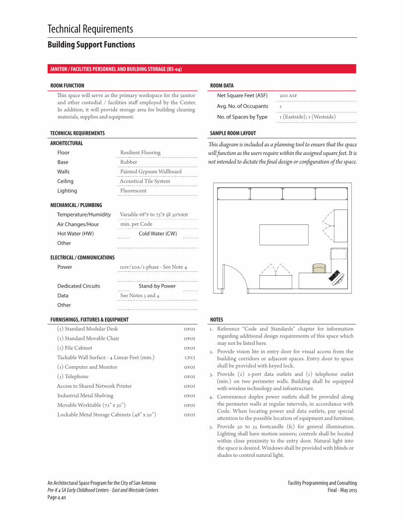
Technical Requirements
An Architectural Space Program for the City of San Antonio Facility Programming and ConsultingPre-K 4 SA Early Childhood Centers - East and Westside Centers Final - May 2013Page 4.40
JANITOR / FACILITIES PERSONNEL AND BUILDING STORAGE (BS-04)
ROOM FUNCTION ROOM DATA
This space will serve as the primary workspace for the janitor and other custodial / facilities staff employed by the Center. In addition, it will provide storage area for building cleaning materials, supplies and equipment.
Net Square Feet (ASF) 200 asf
Avg. No. of Occupants 1
No. of Spaces by Type 1 (Eastside); 1 (Westside)
TECHNICAL REQUIREMENTS SAMPLE ROOM LAYOUT
ARCHITECTURAL
Floor Resilient Flooring
Base Rubber
Walls Painted Gypsum Wallboard
Ceiling Acoustical Tile System
Lighting Fluorescent
MECHANICAL / PLUMBING
Temperature/Humidity Variable 68°f to 75°f @ 50%rh
Air Changes/Hour min. per Code
Hot Water (HW) Cold Water (CW)
Other
ELECTRICAL / COMMUNICATIONS
Power 110v/20a/1-phase - See Note 4
Dedicated Circuits Stand-by Power
Data See Notes 3 and 4
Other
FURNISHINGS, FIXTURES & EQUIPMENT NOTES(1) Standard Modular Desk ofoi 1. Reference “Code and Standards” chapter for information
regarding additional design requirements of this space which may not be listed here.
2. Provide vision lite in entry door for visual access from the building corridors or adjacent spaces. Entry door to space shall be provided with keyed lock.
3. Provide (2) 2-port data outlets and (1) telephone outlet (min.) on two perimeter walls. Building shall be equipped with wireless technology and infrastructure.
4. Convenience duplex power outlets shall be provided along the perimeter walls at regular intervals, in accordance with Code. When locating power and data outlets, pay special attention to the possible location of equipment and furniture.
5. Provide 50 to 55 footcandle (fc) for general illumination. Lighting shall have motion sensors; controls shall be located within close proximity to the entry door. Natural light into the space is desired. Windows shall be provided with blinds or shades to control natural light.
(1) Standard Movable Chair ofoi
(1) File Cabinet ofoi
Tackable Wall Surface - 4 Linear Feet (min.) cfci
(1) Computer and Monitor ofoi
(1) Telephone ofoi
Access to Shared Network Printer ofoi
Industrial Metal Shelving ofoi
Movable Worktable (72” x 30”) ofoi
Lockable Metal Storage Cabinets (48” x 20”) ofoi
This diagram is included as a planning tool to ensure that the space will function as the users require within the assigned square feet. It is not intended to dictate the final design or configuration of the space.
Building Support Functions

Technical Requirements
Facility Programming and Consulting An Architectural Space Program for the City of San AntonioFinal - May 2013 Pre-K 4 SA Early Childhood Centers - East and Westside Centers Page 4.41
CLASSROOM SUPPLY / BULK MATERIALS STORAGE (HIGH DENSITY) (BS-05)
ROOM FUNCTION ROOM DATA
This space is intended for storage of surplus materials utilized for classroom instruction. Items may include construction paper, paints, glue, etc. A high density storage system shall be installed in this location to maximize capacity of this room.
Net Square Feet (ASF) 100 asf
Avg. No. of Occupants n/a
No. of Spaces by Type 1 (Eastside); 1 (Westside)
TECHNICAL REQUIREMENTS SAMPLE ROOM LAYOUT
ARCHITECTURAL
Floor Resilient Flooring
Base Rubber
Walls Painted Gypsum Wallboard
Ceiling Acoustical Tile System
Lighting Fluorescent
MECHANICAL / PLUMBING
Temperature/Humidity Variable 68°f to 75°f @ 50%rh
Air Changes/Hour min. per Code
Hot Water (HW) Cold Water (CW)
Other
ELECTRICAL / COMMUNICATIONS
Power 110v/20a/1-phase - See Note 5
Dedicated Circuits Stand-by Power
Data See Note 4 and 5
Other
FURNISHINGS, FIXTURES & EQUIPMENT NOTES (CONTINUED)High Density Storage System cfci 2. Verify that floor structure is adequate to support the high
density storage system. Coordinate with manufacturer’s specifications.
3. Entry door to space shall be provided with secure (i.e. key card) access.
4. Provide (2) 2-port data outlets and (1) telephone outlet (min.) on two perimeter walls. Building shall be equipped with wireless technology and infrastructure.
5. Convenience duplex power outlets shall be provided along the perimeter walls at regular intervals, in accordance with Code. When locating power and data outlets, special atten-tion should be paid to the possible location of equipment and furniture.
6. Provide 50 to 55 footcandle (fc) for general illumination. Lighting shall have motion sensors; controls shall be located within close proximity to the entry door. This space does not require natural light. If applicable, provide windows with blinds or shades to control natural light.
*Note: An outside vendor will be responsible for the installation of FF&E related to this space. Designer shall provide adequate space and infrastructure to support equipment specified for this space. Consult with vendor for specifications related to this space.
NOTES
1. Reference “Code and Standards” chapter for information regarding additional design requirements of this space which may not be listed here.
This diagram is included as a planning tool to ensure that the space will function as the users require within the assigned square feet. It is not intended to dictate the final design or configuration of the space.
Building Support Functions

Technical Requirements
An Architectural Space Program for the City of San Antonio Facility Programming and ConsultingPre-K 4 SA Early Childhood Centers - East and Westside Centers Final - May 2013Page 4.42

Technical Requirements
Facility Programming and Consulting An Architectural Space Program for the City of San AntonioFinal - May 2013 Pre-K 4 SA Early Childhood Centers - East and Westside Centers Page 4.43
Room Data Sheets Exterior Areas - Children

Technical Requirements
An Architectural Space Program for the City of San Antonio Facility Programming and ConsultingPre-K 4 SA Early Childhood Centers - East and Westside Centers Final - May 2013Page 4.44
OUTDOOR PLAY AREA (EX-01)
ROOM FUNCTION ROOM DATA
This space will provide age-appropriate toys and equipment for outdoor physical activity. It is intended that a variety of play-scapes be provided to give children opportunity to develop a variety of different motor skills.
Net Square Feet (ASF) 1,600 asf
Avg. No. of Occupants 20 + 2 Instructors
No. of Spaces by Type 7 (Eastside); 7 (Westside)
TECHNICAL REQUIREMENTS SAMPLE ROOM LAYOUT
ARCHITECTURAL
Floor
Base
Walls
Ceiling
Lighting
MECHANICAL / PLUMBING
Temperature/Humidity
Air Changes/Hour
Hot Water (HW) Cold Water (CW)
Other
ELECTRICAL / COMMUNICATIONS
Power
Dedicated Circuits Stand-by Power
Data
Other
FURNISHINGS, FIXTURES & EQUIPMENT NOTES (CONTINUED)(1) Swing Set for Four ofci 2. Space should be located adjacent to and accessible from the
General Classrooms to the greatest extent possible.3. Playground designs and equipment shall adhere to the cur-
rent Handbook for Public Playground Safety, U. S. Con-sumer Product Safety Commission, Publication No. 325, the Consumer Product Safety Improvement Act, (CPSIA 2008), ASTM’s F1292-04, F1951-09B and F2075- 04e1, Texas Depart-ment of Family and Protective Services Minimum Standards for Child-Care Centers and the Texas Accessibility Standards.
4. Securely anchor all equipment according to manufacturer specifications to prevent collapsing, tipping, sliding, moving or overturning.
5. Provide proper use zone and surfacing materials under and around a piece of equipment.
6. Provide area (i.e. concrete sidewalk) on which children may draw with chalk.
7. Provide a covered or shaded area, through the utilization of awnings, roof overhangs, or other methods to provide chil-dren with shelter from the sun.
(1) Modular Playscape with Slide ofci
Free-Standing Play Panels ofci
Note: Curriculum had not been developed at the time of publication of this report. Actual playscape equipment will be determined based on final curriculum. Equipment included here is developed from local ISD playground equipment requirements and is included for informational purposes only and subject to change.
Reference information included in previous chapter, “Code and Standards,” for the types of equipment which is / is not allowed for children aged 4 years old as directed by the Texas Department of Family and Protective Services.
NOTES1. Reference “Code and Standards” chapter for information
regarding additional design requirements of this space which may not be listed here.
This diagram is included as a planning tool to ensure that the space will function as the users require within the assigned square feet. It is not intended to dictate the final design or configuration of the space.
For informational purposes, standards and playground configurations approved by the Northside Independent School District have been included in the Appendix of this document.
Exterior Areas

Technical Requirements
Facility Programming and Consulting An Architectural Space Program for the City of San AntonioFinal - May 2013 Pre-K 4 SA Early Childhood Centers - East and Westside Centers Page 4.45
OUTDOOR STORAGE (EX-02)
ROOM FUNCTION ROOM DATA
This space will provide storage for toys and equipment intended for outdoor use. This space should be centrally located to the Outdoor Play Areas which it supports. This is a purely utilitarian space.
Net Square Feet (ASF) 100 asf
Avg. No. of Occupants n/a
No. of Spaces by Type 2 (Eastside); 2 (Westside)
TECHNICAL REQUIREMENTS SAMPLE ROOM LAYOUT
ARCHITECTURAL
Floor Concrete
Base None
Walls Masonry
Ceiling Exposed Structure
Lighting Fluorescent
MECHANICAL / PLUMBING
Temperature/Humidity
Air Changes/Hour
Hot Water (HW) Cold Water (CW)
Other
ELECTRICAL / COMMUNICATIONS
Power
Dedicated Circuits Stand-by Power
Data
Other
FURNISHINGS, FIXTURES & EQUIPMENT NOTESIndustrial Metal Shelving ofoi 1. Reference “Code and Standards” chapter for information
regarding additional design requirements of this space which may not be listed here.
2. Space should be located adjacent to and accessible from the Outdoor Play Areas.
3. Provide double door entry or oversized door to facilitate movement of equipment to / from this space.
4. This space does not require natural light.
Note: Curriculum had not been developed at the time of publication of this report. Actual equipment storage requirements will be determined based on final curriculum. Types of play equipment which might be stored in this area are intended for outside use and will include, but not be limited to, tricycles, wagons, etc.
This diagram is included as a planning tool to ensure that the space will function as the users require within the assigned square feet. It is not intended to dictate the final design or configuration of the space.
Exterior Areas

Technical Requirements
An Architectural Space Program for the City of San Antonio Facility Programming and ConsultingPre-K 4 SA Early Childhood Centers - East and Westside Centers Final - May 2013Page 4.46

Technical Requirements
Facility Programming and Consulting An Architectural Space Program for the City of San AntonioFinal - May 2013 Pre-K 4 SA Early Childhood Centers - East and Westside Centers Page 4.47
Room Data Sheets Non-Assignable Spaces

Technical Requirements
An Architectural Space Program for the City of San Antonio Facility Programming and ConsultingPre-K 4 SA Early Childhood Centers - East and Westside Centers Final - May 2013Page 4.48
Technical Requirements of Non-Assignable SpacesGiven the particular functional needs of the Pre-K 4 SA Early Childhood Centers, the following design considerations should be incorporated into the non-assignable spaces noted below. City of San Antonio Standards shall be reviewed for detailed information concerning these spaces.
1. Housekeeping / Custodial Closets shall be of sufficient size for a slop sink, mop hanger, shelving for cleaning supplies, buckets, vacuums, etc. Provide two closets (min.). One closet should be located in both the public areas and classroom area. This will enhance the security of the children within the instructional area while allowing custo-dial access to equipment and cleaning supplies without the need to transfer items between the general, public areas and secure (ie. card reader access) zones during cleaning/maintenance activities.
2. Data / Telephone Closets shall be designed according to City of San Antonio ITSD Standards, with sufficient condition air over a 24-hour period of operation. MDF and/or IDF rooms shall be provided and sized according to the ITSD Cabling Standards.
3. Provide mechanical space(s) sized appropriately for air handlers, pumps, piping, etc. Also provide separate closet(s) for electrical panels and other necessary electrical equipment. Provide chases as needed.
4. Provide a Loading / Service Area (van-height, minimum) for loading and delivery. This area should have adequate space to accommodate the maneuvering of trucks and dumpsters and shall be screened from view. Provide an area for two dumpsters, minimum (trash and recycling).
Non-Assignable Spaces

Technical Requirements
Facility Programming and Consulting An Architectural Space Program for the City of San AntonioFinal - May 2013 Pre-K 4 SA Early Childhood Centers - East and Westside Centers Page 4.49
MDF / IDF CLOSET
ROOM FUNCTION ROOM DATA
This is a dedicated space which provides a controlled environ-ment to house telecommunications equipment and connect-ing hardware and should be located as close to the center of the building as possible.
Net Square Feet (ASF) 100 asf
Avg. No. of Occupants n/a
No. of Spaces by Type 2 (Eastside); 2 (Westside)
TECHNICAL REQUIREMENTS SAMPLE ROOM LAYOUT
ARCHITECTURAL
Floor Sealed Concrete
Base Rubber
Walls Exposed Structure -See Notes 2, 3
Ceiling Exposed Structure - See Note 3
Lighting Fluorescent
MECHANICAL / PLUMBING
Temperature/Humidity Variable 55°f to 78°f @ 14 -45%rh
Air Changes/Hour min. per Code
Hot Water (HW) Cold Water (CW)
Other
ELECTRICAL / COMMUNICATIONS
Power See Note 6
Dedicated Circuits Stand-by Power
Data
Other
FURNISHINGS, FIXTURES & EQUIPMENT NOTES (CONTINUED)Equipment Cabinet(s) cfci 4. Lighting shall not be placed directly over cable trays.
5. Temperature shall be maintained between 55 degrees Fahr-enheit and 78 degrees Fahrenheit. Relative humidity shall be between 14 percent and 45 percent.
6. Locate two (2) dedicated 120 VAC 60 Hz outlets protected by 20 A circuit breaker directly on the cable tray above the equipment cabinet. In addition, install one (1) dedicated 120 VAC 60 Hz outlets protected by 20 A circuit breaker on the plywood covered wall for service providers approximately 18 inches aff. Aluminum cable sheath, racks, cable trays and shelving shall be grounded per ITSD standards.
7. Provide minimum 48 inches clearance between the front, rear or side of an equipped rack and a wall with communicating components on it. There shall be a minimum 36 inches clear-ance between the front, rear or side of an equipped rack and a blank wall.
8. All wall-mounted cabinets shall be installed so that the top of the cabinet is 72 inches aff.
NOTES1. Reference “Code and Standards” chapter for information
regarding additional design requirements of this space which may not be listed here.
2. One wall shall be completely covered in 3/4” fire rated ply-wood. Plywood shall be installed so that stamps are always vis-ible for inspection and shall never be painted.
3. Ceiling shall be 9’-0” aff. Walls and ceiling finishes shall be treated to eliminate dust. Finishes shall be light in color to enhance room lighting.
This diagram is included as a planning tool to ensure that the space will function as the users require within the assigned square feet. It is not intended to dictate the final design or configuration of the space.
Reference the City of San Antonio “Cabling Standards” prepared by the Information Technology Services Department for the specific requirements of this space type. ITSD should be contacted during the design phase to determine final room design, layout and location.
Non-Assignable Spaces

Technical Requirements
An Architectural Space Program for the City of San Antonio Facility Programming and ConsultingPre-K 4 SA Early Childhood Centers - East and Westside Centers Final - May 2013Page 4.50

5Site Studies


Site Studies
Facility Programming and Consulting An Architectural Space Program for the City of San AntonioFinal - May 2013 Pre-K 4 SA Early Childhood Centers - East and Westside Centers Page 5.1
Introduction
A t the time of publication of this report, the proposed site loca-tions for the new Eastside and Westside Pre-K 4 SA Early Childhood
Centers had not been determined.
Design team shall reference the “Code and Standards” chapter of this document for information specific to the building and landscape design regulations or requirements.

Site Studies
An Architectural Space Program for the City of San Antonio Facility Programming and ConsultingPre-K 4 SA Early Childhood Centers - East and Westside Centers Final - May 2013Page 5.2

6Programming Estimate

Programming Estimate
Facility Programming and Consulting An Architectural Space Program for the City of San AntonioFinal - May 2013 Pre-K 4 SA Early Childhood Centers - East and Westside Centers Page 6.1
Programming Estimate
A t the time of publication of this document, a total project budget for the construction and finish-out of both the Eastside and Westside
centers was not available. It is the intention that the facilities will be con-structed by a developer and leased to the City. The allocated budget will be utilized for tenant fit-out. The budget will continue to be reviewed regularly during the design and construction phases to determine neces-sary adjustments.
A 1/8-cent sales tax was approved by the citizens of San Antonio in November 2012. This sales tax increase has been proposed to generate an estimated $29 million annually towards the construction, operation and maintenance of the early childhood centers. The cost of this investment is estimated to be $7.79 annually per median San Antonio household. In addition, the facilities may be eligible to receive matching state pre-Kinder-garten dollars estimated at between $10 million and $11 million annually.

Programming Estimate
An Architectural Space Program for the City of San Antonio Facility Programming and ConsultingPre-K 4 SA Early Childhood Centers - East and Westside Centers Final - May 2013Page 6.2

7Preliminary Project Schedule

Preliminary Project Schedule
Facility Programming and Consulting An Architectural Space Program for the City of San AntonioFinal - May 2013 Pre-K 4 SA Early Childhood Centers - East and Westside Centers Page 7.1
Introduction
T he Eastside and Westside Centers will be constructed by a developer then leased back to the City. Therefore, the schedule will
be developer-driven with a substantial completion by July 2014.
The schedule is preliminary and will be adjusted as the project moves further through the design phase and as the construction drawings are developed. Items which may affect schedule include funding, permitting, construction document quality, contractor bids, contractor quality, and weather:
� Availability of materials: Now that Texas and U.S. economies are part of the global economy, major movement in demand on a global basis can impact the availability of materials here. This factor will also impact the cost of materials. National swings in supply and demand will also continue to influence material availability.
� Availability of labor: Stagnant economies, such as we are experiencing at this writing, are generally unfavorable, but often have the effect of keeping subcontractors less busy, which can have a positive impact on the schedule.
� Weather: Contractors normally calculate a reasonable amount of bad weather days in their schedules, but unusually wet or otherwise inclement weather can negatively impact the schedule. The best way to keep a project on schedule is to diligently manage those items that can be controlled. These include selecting the highest quality contractors and sub-contractors available, producing a clear, concise, well-coordinated set of construction documents, diligently preparing for and pursuing approvals, encouraging communication among all parties on the project, and monitoring construction progress.

Preliminary Project Schedule
An Architectural Space Program for the City of San Antonio Facility Programming and ConsultingPre-K 4 SA Early Childhood Centers - East and Westside Centers Final - May 2013Page 7.2

8Appendix


AAppendix


City of San Antonio Early Childhood Centers of Excellence Preliminary Meeting with NISD Page 1 July 9, 2012
Meeting Notes City of San Antonio Early Childhood Centers of Excellence Preliminary Meeting w/Northside Independent School District – July 9, 2012 Original Distribution: July 9, 2012 Revised Distribution: July 10, 2012 Attendance City of San Antonio (CoSA): Jeff Rodriguez Project Control Manager Northside Independent School District (NISD): Bill Peters School Property Analyst – Facilities and Operations Mike Boehmer Project Manager – Engineering Services Facility Programming and Consulting (FP&C): Bryan Sibille Project Manager Molly Cundari Senior Facility Programmer Meeting Overview: The notes provided below are in reference to the initial meeting with NISD regarding the Early Childhood Centers of Excellence proposed by the Mayor’s SA2020 Brainpower Initiative Task Force. As part of the Mayor’s SA2020 Brainpower Initiative, two early childhood
centers have been proposed – one on the north and one on the south side of town.
Three items have been identified in the Mayor’s initiative for the project scope and type of program City wants to administer: classroom education, full-time daycare and a laboratory/model for teaching teachers how to teach.
In addition to typical educational facility needs, this facility will require conference room(s) for mentoring teachers and parents, as necessary.
Typically, NISD plans for two sizes of elementary schools (pre-K to 5th grade) – 660 students or 800 students. No matter which size school is being planned, the cafeteria is designed for the 800 student class size.
Catering food in for lunch has been proposed, in lieu of a full service cafeteria.
Serving breakfast should also be a consideration.
Jeff Rodriguez has the NISD standard design guidelines which he will be able to share with the planning team. In addition, JR mentioned it would be useful, once the sites have been determined, to collect information on the existing education programs offered at facilities within a certain radius of the site to ensure that it would complement and not compete with these existing programs.

City of San Antonio Early Childhood Centers of Excellence Preliminary Meeting with NISD Page 2 July 9, 2012
A site within the Medical Center has been discussed as one potential location for the north side center. Currently, Meade Elementary, which offers pre-K programs, and the NISD district-wide program for immigrant students are located in this area.
Recreation and physical activity space will also be critical in the design of the new facility, especially as it relates to the daycare component.
NISD has recently updated the playground standards in their Design Guide. Mike Boehmer will provide the latest information regarding playgrounds to the planning team.
Linda Seewald, NISD Director of Health and Physical Education, was also referenced as a good information source regarding the playground design and acceptable materials for equipment and surfacing.
At a minimum, kindergarten playgrounds are to include a swingset (8’-0”), a playscape with slides and a geodesic dome. Engineered wood fiber (EWF) materials are utilized for the equipment fall zones and the playground area surfacing. Rubber wear mats are installed in the middle of the EWF depth, under the swing seat areas and at the bottom of the slides.
Engineered wood fiber is installed at a 12-inch depth to accommodate the compacting of materials (min. 10-inch thickness required per CPSC Playground Guidelines, Pub. 325). This material, if maintained properly, will meet ADA and ASTM F1951 requirements for accessibility.
NISD provides at least one concrete pathway (sidewalk) accessible route leading to the play area and a concrete transition ramp, terminating beneath the engineered wood fiber surfacing that allows for wheelchair accessibility into the playground from the accessible route.
Rick Berry, Registered Accessibility Specialist, (RAS) was referenced as a point-of-contact for playground accessibility requirements.
New Texas Accessibility Standard (TAS) guidelines may impact the playground design and should be considered in the facility planning.
NISD does not currently utilize shade canopies. However, it is a Northeast ISD requirement and should be included in the facility programming for the moment. NEISD should be able to provide the typical requirements for this feature when FP&C meets with them.
Federal guidelines for the Head Start programs should be utilized as the basis for the preliminary planning and design. This ensures that the facility will be eligible to apply for federal funds, if it desires, in the future.
END OF MINUTES If any of the participants have any clarification, comments, additions or corrections to be made to these minutes, please submit them to Molly Cundari (email: [email protected]) within 3 business days.

City of San Antonio Early Childhood Centers of Excellence Preliminary Meeting with CoSA Education Policy and Services Administrator Page 1 July 10, 2012
Meeting Notes City of San Antonio Early Childhood Centers of Excellence Preliminary Meeting w/CoSA Education Policy and Services Administrator – July 10, 2012 Distribution: July 11, 2012 Attendance City of San Antonio (CoSA): Rebecca Flores Education Policy and Services Administrator – City
Manager’s Office Bill Hensley Project Manager - CIMS Facility Programming and Consulting (FP&C): Bryan Sibille Project Manager Molly Cundari Senior Facility Programmer Meeting Overview: The notes provided below are in reference to the initial meeting with the Education Policy and Services Administrator in the City Manager’s Office regarding the Early Childhood Centers of Excellence proposed by the Mayor’s SA2020 Brainpower Initiative Task Force. Rebecca Flores provided an overview of the Brainpower Initiative and its
goal to provide businesses with a better educated workforce. It was decided to work to achieve this goal through a concentration on early childhood education. It is envisioned that this could result in economic development of the city in the future in its ability to attract companies to the area which require a higher skilled/educated labor forces.
A 1/8 cent sales tax has been proposed to be included on the November ballot. If approved, the tax will generate approximately $125 million over the next 5 years.
Head Start has been proposed as the model for the basic facility design but there is concern that it may not be possible to achieve all of the federal design requirements due to the budget concerns. The proposed facility design should strive to be the best teaching environment possible in order to attract/recruit the best educators.
Community School program offered in New York City through the Children’s Aid Society was also discussed briefly as a program which may have functions desired for the new centers, although on a much smaller scale and without the community health services offered (medical, dental clinics, etc.).
As the program may only be funded for the next 5 years, there is an awareness that the money needs to be spent wisely, buying the best facilities possible, within the allocated budget.

City of San Antonio Early Childhood Centers of Excellence Preliminary Meeting with CoSA Education Policy and Services Administrator Page 2 July 10, 2012
Two new centers will be constructed on the north and south side with approximately 350 students each (ages 4 to 5). A low student to teacher ratio of 15 students to one teacher and one teaching assistant is the goal. In addition, the new facilities will serve as teaching labs for professional development of local teachers (+/- 550 individuals city-wide) and for those studying to enter the education profession.
In addition, the centers will be used for community outreach through parent development and related workshops which will allow parents to engage with certified teachers and learn how to help their children advance while outside the classroom through activities such as reading to them/together.
It was noted that the requirements for what makes the best model early childhood education center are fairly easy to outline. However, the type of facility that the City is proposing is, with the community outreach/professional development services and components, is unique and will be a challenge.
Any component of the center which is community outreach or will have general public access should be segregated and distinct from the classrooms and children for security/safety. Consider placing these components on the exterior perimeter of building when designing.
Ideally, the classrooms/children’s areas could be locked down/secured separately, but the common/public area could still be easily accessed allowing for weekend/after-school activities.
Curriculum is still being developed. However, it is agreed that any curriculum will revolve around movement of children within the classroom through the creation of “learning centers” where children will learn through activities and manipulating their environment.
Centers will require ADA and handicap/special ed accessibility/capability but will not serve the most severely handicap students. These students will receive assistance/education at other facilities city-wide which are specialized in education of these types of individuals and have the proper facilities to accommodate them.
Parents should feel welcome and the centers should be designed in a manner which promotes the community to take ownership of it and pride in it, encouraging parents to be involved and volunteer, as well.
Parents and community members that enter the building should first and foremost feel that students are safe and a second goal is that they feel welcomed.
Entry lobby/foyer should have a place for a monitor (who will check ID of visitors) and direct guest to where training will take place. The space should have a more “living room” type of feel and provide places for children’s work to be displayed.
Exterior signage will be important in providing the center with an identity and visibility to pedestrian and vehicular traffic passing by.
Technology will be integral to the classrooms and throughout the building (i.e. WiFi, projectors, etc.). Cameras will be utilized for surveillance of the

City of San Antonio Early Childhood Centers of Excellence Preliminary Meeting with CoSA Education Policy and Services Administrator Page 3 July 10, 2012
public/communal spaces, lobbies, building entries, etc. but will not be included in the classrooms at this time.
An internal discussion with the teachers will be necessary to determine to what extent cameras are desired in the classroom. At the moment, they may provide an opportunity for training purposes and desirable if controlled by the teachers. Surveillance of the classrooms will likely be objected to.
Administrative Areas
A “gatekeeper” should be located at the building entry to reinforce the sense of safety and security of the children and the parents. This person will monitor access to areas where the children will be located. Children’s’ areas should be segregated from the public areas to the greatest extent possible to provide the greatest safety/security of the children.
Personnel will include those related to administration, attendance, discipline. A director/principal and assistant director/principal will likely be located at each center. These should be a traditional office with area for clerks and student record storage.
Support spaces, including two conference rooms for up to 10 individuals (parent/teacher meetings, internal faculty meetings, etc.) and file/storage rooms will also be required.
Two speech therapists will require space to assess students and assist with learning. Plan for up to two students per therapist at any time. These offices should be located with other administrative offices as they are part-time positions and it is desired they be housed in a central location where the children will be brought to, instead of going to the individual classrooms.
A nurse’s office should also be included. Office should have desk with phone to allow for required paperwork (by law) to be completed, file storage (for student records, etc.). A sink and bed should also be provided for students to lie down.
Classrooms
Classrooms will be focused around learning centers rather than a traditional classroom setting.
Children primarily will be working in small groups of 3 to 5 (e.g., one group will be reading a book on apples, another group will be drawing an apple, another group will be doing a science activity with apples. Then after a specified amount of time, the kids would rotate to the next center.)
Classrooms also should be conducive for entire class activities (e.g., story-time with the teacher).
At any time, it is possible there will be up to 4 adults in the classroom with the children (teacher, teaching assistant, plus two professionals or student teachers).

City of San Antonio Early Childhood Centers of Excellence Preliminary Meeting with CoSA Education Policy and Services Administrator Page 4 July 10, 2012
Classrooms should be configured in pods of four with shared sink/counter/cabinet area and toilet facilities between each. No changing area is required at this time. Consider inclusion of wall-mounted changing table in toilet, if necessary.
Pods of five classrooms were originally recommended in the Brainpower Initiative. It was decided in the meeting that pods of four classrooms were more functional and more cost-effective to develop.
A storage closet for instruction related supplies should also be located in each classroom (for supplies and books). Cubbies to store manipulatives and art supplies and counterspace for art work to dry/be displayed will also be required.
Teachers will be provided a teaching station within each classroom. No faculty lockers will be provided. Personal belongings will be stored in individual classrooms.
Natural light in classrooms is desired. Also, windows should be provided from the hallway into the classrooms to allow observation without entering the classroom and for additional security.
Dutch doors should be considered at classroom entrance to control children egress from the space.
Exterior doors should be provided to an outdoor play area.
Other Spaces
Exterior playscapes will be required. These may be shared between two pods of classrooms and may provide a variety of equipment to allow for maximum flexibility/experiences during outdoor physical activities.
Play grounds should be built using Head Start regulations. NISD has also provided the planning team with their standard design requirements.
Ideally, each pod should have one playground (total of four-six play grounds per center). Discussion regarding one central playground vs. multiple shared playgrounds (between pods) occurred. It was decided that one large playground would be hard for teachers to ensure student safety. Rebecca Flores asked if it was possible to cost out the difference between a Head Start playground vs. minimum state required playground to assist in determining which type to design.
It is desired that each playground have a different set of equipment so children could rotate and use the other playgrounds to enrich their outdoor experience.
Indoor play areas, beyond that included in classrooms, as outlined in the Brainpower Initiative, is not a high priority unless it is deemed a requirement due to local air quality conditions. The preference is for children to play outside.
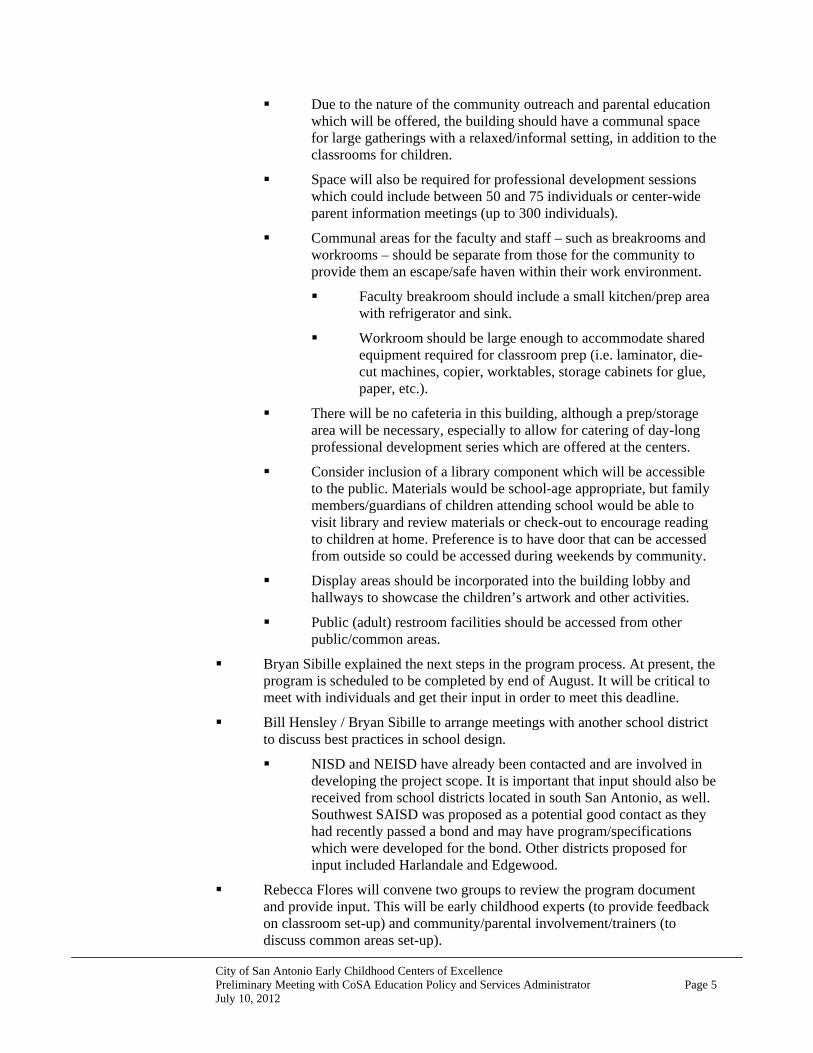
City of San Antonio Early Childhood Centers of Excellence Preliminary Meeting with CoSA Education Policy and Services Administrator Page 5 July 10, 2012
Due to the nature of the community outreach and parental education which will be offered, the building should have a communal space for large gatherings with a relaxed/informal setting, in addition to the classrooms for children.
Space will also be required for professional development sessions which could include between 50 and 75 individuals or center-wide parent information meetings (up to 300 individuals).
Communal areas for the faculty and staff – such as breakrooms and workrooms – should be separate from those for the community to provide them an escape/safe haven within their work environment.
Faculty breakroom should include a small kitchen/prep area with refrigerator and sink.
Workroom should be large enough to accommodate shared equipment required for classroom prep (i.e. laminator, die-cut machines, copier, worktables, storage cabinets for glue, paper, etc.).
There will be no cafeteria in this building, although a prep/storage area will be necessary, especially to allow for catering of day-long professional development series which are offered at the centers.
Consider inclusion of a library component which will be accessible to the public. Materials would be school-age appropriate, but family members/guardians of children attending school would be able to visit library and review materials or check-out to encourage reading to children at home. Preference is to have door that can be accessed from outside so could be accessed during weekends by community.
Display areas should be incorporated into the building lobby and hallways to showcase the children’s artwork and other activities.
Public (adult) restroom facilities should be accessed from other public/common areas.
Bryan Sibille explained the next steps in the program process. At present, the program is scheduled to be completed by end of August. It will be critical to meet with individuals and get their input in order to meet this deadline.
Bill Hensley / Bryan Sibille to arrange meetings with another school district to discuss best practices in school design.
NISD and NEISD have already been contacted and are involved in developing the project scope. It is important that input should also be received from school districts located in south San Antonio, as well. Southwest SAISD was proposed as a potential good contact as they had recently passed a bond and may have program/specifications which were developed for the bond. Other districts proposed for input included Harlandale and Edgewood.
Rebecca Flores will convene two groups to review the program document and provide input. This will be early childhood experts (to provide feedback on classroom set-up) and community/parental involvement/trainers (to discuss common areas set-up).

City of San Antonio Early Childhood Centers of Excellence Preliminary Meeting with CoSA Education Policy and Services Administrator Page 6 July 10, 2012
Bill Hensley / Bryan Sibille to schedule a meeting with the planning team and ITSD within the next two weeks to ensure their input is received on and included in program regarding technology/data/security needs. Rebecca Flores recommended that technology representatives from the school districts also be included. She will also provide ITSD with an overview of the Texas security requirements for this type of facility and adult screening (SB-9 regulations, mandated security technology, such as RAPTOR, to do quick check on visitors, etc.).
END OF MINUTES If any of the participants have any clarification, comments, additions or corrections to be made to these minutes, please submit them to Molly Cundari (email: [email protected]) within 3 business days.

City of San Antonio Early Childhood Centers of Excellence Preliminary Meeting with NEISD Page 1 July 12, 2012
Meeting Notes City of San Antonio Early Childhood Centers of Excellence Preliminary Meeting w/Northeast Independent School District – July 12, 2012 Original Distribution: July 24, 2012 Attendance Northeast Independent School District (NEISD): Garrett Sullivan Executive Director - Construction Management & Engineering Jorge Cabello Senior Director – Construction Planning and Design Facility Programming and Consulting (FP&C): Bryan Sibille Project Manager Shelly Whidby Senior Facility Programmer Meeting Overview: The notes provided below are in reference to the initial meeting with NEISD regarding the Early Childhood Centers of Excellence proposed by the Mayor’s SA2020 Brainpower Initiative Task Force. As part of the Mayor’s SA2020 Brainpower Initiative, two early childhood
centers have been proposed – Jorge Cabello was present at the original site meeting approx three weeks ago and as a representative of NEISD expressed his concern and opinions for all proposed sites.
In response Mr. Cabello provided the city a set of guidelines for site selection NEISD utilizes when selecting sites. He also stated the existing Interlocal Agreement NESID has with the City states schools will not be constructed on existing major arteries to avoid causing additional traffic congestion.
Mr. Cabello stated the city indicated there would be a follow up meeting with a new set of potential sites for evaluation.
Mr. Sibille and Mr. Cabello acknowledged Rebecca Flores would be the lead on this project in terms of the Administrative Educational component. Mr. Sibille noted his understanding from Ms. Flores that these centers would be both administrative and educational. It was discussed that Ms. Flores has also indicated there was no existing model for this center and that we (Facility Programming and Consulting) would be developing this model by August 24th. Mr. Sibille provided Mr. Cabello an overview of what the program document would encompass.
Mr. Sibille asked Mr. Cabello his thoughts on this center and if NEISD was currently running any similar facilities. Mr. Cabello is not currently operating a facility like the proposed. NEISD houses Pre-K facilities within elementary schools. They do not have a standalone Pre-K facility.
Mr. Cabello stated NEISD elementary schools are planned for 1,000 students grades Pre-K to Fifth. Creating a “6” House System (1 House per grade level) or a “3” House stacked system if the facility is 2-story. In a stacked housed

City of San Antonio Early Childhood Centers of Excellence Preliminary Meeting with NEISD Page 2 July 12, 2012
system the upper grades three through five are located on the second floor. Layout is always site dependent.
Mr. Cabello suggested speaking with SAISD as he thought they might have some dedicated Pre-K stand alone facilities.
Mr. Cabello stated he would be happy to share the standards NEISD currently uses for Pre-K classrooms and shared the drawings for a current school under construction, The Vineyard, as an example.
Mr. Cabello stated one of the main reasons he shared The Vineyard as an example was to show us the classroom technology. NEISD feels it is important to set-up classrooms to be adaptable to current and future digital media. Classroom design must be flexible to support the charging of all technology as well. An NEISD “Classroom of the Future” has (2) Smartboards, (12’ Linear) section of dry erase board, a media cabinet with capability to hang an LCD TV, (2) short throw projectors and multiple media outlets. Mr. Cabello stated NESID would be happy to share their technology specifications with us. Most important part is contacting a vendor who can order, install and warranty all technology.
Mr. Garrett Sullivan joined the meeting at this point.
Mr. Sibille presented Mr. Sullivan a brief overview of previous topics discussed with Mr. Cabello and the meeting moved forward from that point.
Mr. Sullivan asked how many children each center was planning to serve. Mr. Sibille indicated the original “Brainpower” documents had indicated 350 children at a student teacher ratio of 15 to 2 would be served at each center.
Mr. Sullivan showed FPC an example of the “houses” currently under construction for The Vineyard elementary school. It was noted the classrooms are a minimum of 800 asf each to meet TEA standards and each set of two has direct access to private restrooms. This allows the younger children to be more closely monitored. The “house” also has a larger gathering type area in the corridor at approx 800 asf. Mr. Sullivan indicated this space helps elevate congestion in the morning and evening when the house is entering exiting its classrooms and is also equipped with a smartboard and can be utilized as an additional teaching space.
Mr. Sullivan indicated each house also has a (2) larger, 900 asf, self-contained classrooms for special needs. This space has a larger, 200 asf, shared ADA restroom with a shower and full size hospital bed to meet these students’ special needs. These spaces are intended to accommodate 10 students each.
Mr. Sullivan reviewed some other standard attributes of NEISD classrooms.
A wet station is provided in each room. The station has an ADA sink with full height backsplash and utilizes solid surface countertops.
(25) Built-in cubbies for student books, coats and materials.
Technology for a “classroom of the future” (see notes above for items contained in this category).
Tackable wall surface on all interior walls. Exterior wall does not have tackable surface to help detour mold growth. (Mr. Sibille asked about

City of San Antonio Early Childhood Centers of Excellence Preliminary Meeting with NEISD Page 3 July 12, 2012
the longevity of the tackable surface. Mr. Sullivan said it should outlast the building.)
Interior corridor walls of each house have tackable surface from approx 3’-6” Tall to 7’ High. Verify not more than 25% of wall surface is combustible material with Fire Marshal.
Mr. Sibille asked if NEISD had installed any dutch doors in Pre-K or K Classrooms and how they felt about the doors. Mr. Sullivan and Mr. Cabello stated they did not have any dutch doors in district facilities. The only concern they had with installation of dutch doors would be corridor noise polluting the classroom.
Mr. Sibille asked about interior windows from the classroom to the corridor. NESID does not provide these as they feel the large full door length side lite next to each classroom door is a sufficient visual connection to the corridor. They also prefer to utilize the wall space for the media cabinet and felt it might cause a distraction for the students.
Mr. Sullivan provided FPC with a list of the standard sizes they used for program design of the Vineyard school which included a 3,600 asf gymnasium.
Mr. Sullivan provided FPC with a view preferred materials and vendors / installers they utilize in the construction of new NEISD schools on a regular basis:
Resilient sports flooring called Gerflor by Vector Concepts
Playgrounds by Miracle Playscapes – They have a standard for upper grades 3-5 and lower grades Pre-K – 2. Contact is Ahearns
Austin Sign Resources provides all classroom and way finding signage. Representative is Maryann Koons.
Mr. Cabello said he would provide us (FPC) with the information necessary to contact Mr. Tom Johnson, the NEISD Technology Senior Director to set-up or answer questions for the City’s ITSD department in regards to school technology.
END OF MINUTES If any of the participants have any clarification, comments, additions or corrections to be made to these minutes, please submit them to Bryan Sibille ([email protected]) within 3 business days.


City of San Antonio Early Childhood Centers of Excellence Second Meeting with NISD Page 1 July 12, 2012
Meeting Notes City of San Antonio Early Childhood Centers of Excellence Preliminary Meeting w/Northside Independent School District – July 12, 2012 Original Distribution: July 24, 2012 Attendance City of San Antonio (CoSA): Bill Hensley Architect – City Architects Office Andrea Salazar Intern – City of San Antonio Northside Independent School District (NISD): Bill Peters School Property Analyst – Facilities and Operations Leroy San Miguel Assistant Superintendent – Facilities and Operations Facility Programming and Consulting (FP&C): Bryan Sibille Project Manager Shelly Whidby Senior Facility Programmer Meeting Overview: The notes provided below are in reference to a secondary meeting with NISD regarding the Early Childhood Centers of Excellence proposed by the Mayor’s SA2020 Brainpower Initiative Task Force. Mr. San Miguel opened the meeting with clarifying how the NISD district
differentiates between the Headstart Program and their Pre-K Programs. He felt it was important to clarify NISD felt Pre-K was an educational / instructional experience during a portion of a normal student school day and not a daycare type of program with extended hours and less instruction. Pre-K is more structured than Headstart. Mr. Sibille indicated even though the proposed two facilities would have extended hours they were aiming for instruction and curriculum like that of a Pre-K program.
Mr. San Miguel had previous administrative experience with the SAISD school district and was able to provide some additional information and also suggested we speak to that district because they have some stand alone facilities for younger children.
o SAISD decided Pre-K should be more of a separated entity. SAISD developed three models for pods of 2, 4 or 6 dependent on the need and population of each area.
o SAISD facilities have a separate drop off and pick up area.
o SAISD Pre-K students have food service in the classrooms.
o SAISD Pre-K students have restrooms in the classrooms.
o Mr. SanMiguel suggested contacting Kamal ElHabr at SAISD for additional information.

City of San Antonio Early Childhood Centers of Excellence Second Meeting with NISD Page 2 July 12, 2012
Mr. SanMiguel noted NISD integrates it Pre-K classrooms at the elementary schools. Bill Peters will find out who is over the NISD Pre-K curriculum and provide FPC their contact information.
Mr. SanMiguel suggested reaching out to the TEA for teaching requirements for Pre-K classrooms. NISD students do not have separate gym, computer lab, music and or library facilities because they have access to these facilities within each elementary school. He is unaware of the requirements in these areas for a standalone Pre-K.
Mr. SanMiguel suggested looking at the collaborative downtown Navaro School which was a Pre-K Collaborative with SAISD and UTSA.
Mr. Sibille asked Mr. SanMiguel if a representative from his ITSD department would be willing to meet with an ITSD representative from the City of San Antonio and from NEISD so all could collaborate and provide the CoSA ITSD with guidance when dealing with Elementary School technologies. He said he would be happy to have a representative from NISD meet with the City and he would also be happy to share the NISD technology standards with FPC and the City. Bryan should contact Ms. Lori Jones, Assistant Superintendent for Technology Services in the District, to coordinate and ITSD meeting. Mr. SanMiguel will give her a heads up.
Mr. SanMiguel also suggested FPC look into the Region 20 regquirements for schools. Region 20 provides curriculum guidelines for all area districts, NISD, NEISD, SAISD, Edgewood, etc. Dr. Caroline Castile, a former SAISD employee familiar with the early childhood program, now works for Region 20.
There was also a round table discussion about the important of demographics and how they should be considered and studied by an outside entity before committing to site locations on the north and south side of San Antonio.
END OF MINUTES If any of the participants have any clarification, comments, additions or corrections to be made to these minutes, please submit them to Bryan Sibille (email: [email protected]) within 3 business days.

City of San Antonio Early Childhood Centers of Excellence Progress Meeting with CoSA Assistant City Manager Page 1 July 19, 2012
Meeting Notes City of San Antonio Early Childhood Centers of Excellence – Brainpower Initiative Progress Meeting w/ CoSA Assistant City Manager – July 19, 2012 Distribution: July 24, 2012 Attendance City of San Antonio (CoSA): Peter Zanoni Assistant City Manager – City Manager’s Office Mike Etienne Assistant Director – CIMS Razi Hosseini Assistant Director, P.E., R.P.L.S. - CIMS Facility Programming and Consulting (FP&C): Bryan Sibille Project Manager Shelly Whidby Senior Facility Programmer Meeting Overview: The notes provided below are in reference to the progress meeting with the Assistant City Manager, Peter Zanoni, in his office regarding the Early Childhood Centers of Excellence proposed by the Mayor’s SA2020 Brainpower Initiative Task Force. Peter Zanoni began by stating the original assumption of a 33,000 gsf facility
serving 300-350 students had been edited per a city meeting yesterday (July 18th). Mr. Zanoni stated the meeting yesterday outlined:
Enroll 20 students per class
The north side and south side facilities shall serve 500 students each (each site must accommodate this in a current building or have space to accommodate growth)
Decide if it is more cost effective to build for 500 students now or grow the facilities in approx 5 years time. – Stated by others in the room it would be more cost effective to complete full build-out at once
Derrick Farell will provide Mr. Zanoni with a full business plan that he will pass on to FPC
Mr. Zanoni suggested we tour Tynan School – A previous SAISD Elemenatry School now only serving Pre-K Students
It was stated the overall goal is now to open four centers total instead of the initially planned eight
Bryan Sibille provided an overview for the group of what facility programming will provide Mr. Zanoni and the design architect. It was explained the first step would be a proposed spacelist for the facility which would be provided by this Friday (July 20th). Mr. Sibille informed Mr. Zanoni FPC would be following TEA guidelines in our programming efforts for spaces and requirements. At this point Mr. Zanoni stated this center

City of San Antonio Early Childhood Centers of Excellence Progress Meeting with CoSA Assistant City Manager Page 2 July 19, 2012
would not be associated with any ISD and would be more of an advanced child care facility with teaching components and would follow Child Care Center Guidelines. Mr. Zanoni called in “John” at this point to confirm. John stated the project would be following daycare licensing guidelines from the Department of Family and Protective Services. Mr. Sibille noted we would research and follow these guidelines and this would probably impact square footage.
A question was asked regarding the funding of these centers if they were not linked to a school district or TEA. Mr. Zanoni stated parents would register their children in their own school districts and the school district would send the children and the funding dollars for those children to the city’s Brainpower initiative.
Mr. Sibille let them know the spacelist provided tomorrow (July 20th) would follow the requirements of a daycare facility. Mr. Zanoni also stated the project would not be dealing with Headstart or their regulations either.
Mr. Zanoni expanded on the growth plan for reaching 500 students per center:
Year 1 – Opening shall have 350 students a center (2 centers)
Year 2 – Shall have 375 students a center (2 centers)
Year 3 – Shall have 425 Students a center (2 centers)
Year 4 – Shall have 475 students a center (2 centers)
Year 5 – Shall have 500 students a center (2 centers)
Mr. Mike Etiennne says he has some concerns if they will be able to get 350 students a center in the opening year.
Mr. Hosseini indicated he would like FPC to meet with Debra Dockery within the next week to present her what information we have. Mr. Sibille said FPC would be happy to meet with her and Mr. Hosseini said he would set-up a meeting.
Mr. Etienne asked when he will have the necessary information to get the design architect involved in the project. Mr. Sibille said he would a preliminary space list to him tomorrow and the next step would be adjacency diagrams and then finally room data sheets. Mr. Sibille stated we would meet the schedule agreed to in the contract. Mr. Sibille stated the spacelist provided tomorrow would provide the architect a good assumption of building size to begin blocking options on various sites. Mr. Sibille also suggested the city meet and review the spacelist before presenting it to Ms. Dockery. Mr. Zanoni said he agreed and would send out a meeting notice for tomorrow morning (July 20th) to review the spacelist.
Mr. Zanoni asked what type of kitchen would be indicated in the spacelist for the facility. Mr. Sibille stated we had previously been lead in the direction of providing a warming kitchen with adequate storage for heated serving carts, a dry good pantry and a commercial refrigerator or walk-in refrigerator. Mr. Zanoni agreed with providing a warming kitchen with meals provided by an outside vendor. Mr. Sibille also noted this kitchen shall require exterior access for delivery of meals and other goods and it shall also be located on a

City of San Antonio Early Childhood Centers of Excellence Progress Meeting with CoSA Assistant City Manager Page 3 July 19, 2012
main building corridor for easy access to student classrooms when providing meals and snacks. Mr. Sibille asked if the facility would be serving breakfast and Mr. Zanoni said yes they would.
It was discussed that approximately and acre of fenced space would be necessary for a playground if the facility provided 80 gsf of space for every student (500 per center).
Mr. Zanoni indicated at this time they were considering the southwest facility off I-10 to be the location of the north side center. He stated their was additional land at the site and the site could house modular buildings if necessary. Mr. Sibille suggested this be looked at further as daycare spaces usually require self-containment and they may not be able to house students in modular classrooms.
Mr. Zanoni also stated he felt VIA would work with the city to provide free or reduced fares for parents brining their children to the centers. This would require a drop-off / pick up bus lane or area to accommodate a VIA bus at each of the centers.
It was discussed the southwest site may have parking issues. Mr. Etienne stated TIA is looking into the parking / traffic implications of the site.
Mr. Zanoni stated he would provide us the employee counts for the first year that “Matthew” had provided him. Mr. Zanoni went on to say he thought there would be:
Director
Assistant Directors
(35) Teachers and (35) Teacher Aides (number may be adjusted pending number of classrooms required to support 20 students per class)
Case Workers
License Vocational Nurse
Administrative Assistant
Mr. Sibille let Mr. Zanoni know that Ms. Rebekah Flores also sent an email asking for (13) Cubicle Areas for staff involved with Training at all centers and schools. The building will also house (2) Training Rooms for 50 to 60 individuals.
Mr. Zanoni suggested the (13) Admin Ms. Hodges was referring to along with approx (10) District Admin Folks associated with this initiative could all be housed at the south side center and not at the southwest location because of space constraints. Mr. Zanoni will provide FPC a list of the approx (10) District Admin individuals.
Other suggestions for the facility included a student library / parent resources center, possibly a gymnasium or gross motor skills area and a few speech therapy rooms. Mr. Sibille noted the facility will also need a facilities area for janitorial services and storage.

City of San Antonio Early Childhood Centers of Excellence Progress Meeting with CoSA Assistant City Manager Page 4 July 19, 2012
It was noted at this time the project did not have a specific name or title, but could be referred to as the Education Excellence Center or the Model Centers.
The UIW site was also briefly discussed. It was noted this site may be easier to renovate, but would present other complications due to its multiple tenant situation. It would not be a standalone facility.
Mr. Zanoni spoke on behalf of his vision for the project as a highly functioning daycare center focused on education. He sees the center as a fun and dynamic place – a place people associate recognition with.
END OF MINUTES If any of the participants have any clarification, comments, additions or corrections to be made to these minutes, please submit them to Bryan Sibille (email: [email protected]) within 3 business days.

City of San Antonio Early Childhood Centers of Excellence Progress Meeting with CoSA Assistant City Manager and Ed. Policy Administrator Page 1 July 20, 2012
Meeting Notes City of San Antonio Early Childhood Centers of Excellence – Brainpower Initiative Progress Meeting w/ CoSA Assistant City Manager and Ed. Policy Administrator – July 20, 2012 Distribution: July 24, 2012 Attendance City of San Antonio (CoSA): Peter Zanoni Assistant City Manager – City Manager’s Office Rebecca Flores Education Policy and Services Administrator – City
Manager’s Office Mike Etienne Assistant Director – CIMS Razi Hosseini Assistant Director, P.E., R.P.L.S. - CIMS Facility Programming and Consulting (FP&C): Bryan Sibille Project Manager Molly Cundari Senior Facility Programmer Meeting Overview: The notes provided below are in reference to the progress meeting with the Assistant City Manager and Education Policy and Services Administrator regarding the Early Childhood Centers of Excellence proposed by the Mayor’s SA2020 Brainpower Initiative Task Force. Bryan Sibille confirmed that FP&C had been directed to program the facility
as a daycare, instead of a school. The maximum number of students at full build-out would still be 500 with an estimated 20 students per classroom.
Bryan Sibille presented three preliminary space lists for discussion based on previous meeting discussions.
Option 1: Including all desired components for classrooms, professional development components and all administration (center and professional development) – 48,000 gsf
Option 2: Classrooms, professional development and center administration – 44,600 gsf
Option 3: Classrooms and center administration only – 33,200 gsf
Both centers will generally utilize the same base program. The Southside center will also include the administration for the professional development component of the centers as there is more space available at this location (new construction).
It was decided that Option 3, although a good fit for the Southwest Airlines Building (+/- 30,000 gsf), was not a desirable option as it did not include any of the professional development component.

City of San Antonio Early Childhood Centers of Excellence Progress Meeting with CoSA Assistant City Manager and Ed. Policy Administrator Page 2 July 20, 2012
Option 1 was discussed as the ideal program for the Southside development. This location would house the staff required for the professional development component. Peter Zanoni will provide FP&C with the projected staffing requirements so that this component may be sized appropriately.
Option 2 was decided to be a good basis for the Northside program, with some modifications.
The group decided that some of the instructional spaces could be utilized in the short-term for the professional development aspects, such as training and the library.
The original 25 classrooms would be constructed. However, only the number required to manage the initial 350 students (approx. 18 classrooms) would be fit out for this purpose. The remaining classrooms (7) would be utilized in the short-term for training room, library and gross motor skills area.
As the program grows to 500 students, these functions would be relocated into portables outside the building. The remaining classrooms would then be renovated (through furniture change) for the children’s instruction.
Outdoor playground area was also discussed. It is required by state licensing regulations that play area (min. 80sf per child) be provided for at least 25% of the projected capacity of the daycare. This resulted in the need for at least 10,000sf of playground area for 125 children (25% of 500 max. capacity).
Due to the difficulty of controlling such a large amount of playground area and this number of children at one time, it was decided that multiple smaller playgrounds should be provided, instead of one large playground. This would also allow for the variety of playscape equipment which had been discussed in previous meetings.
Although not required by licensing regulation, the Nurse’s Office is a desired component of the program and should be included.
Food service/distribution was discussed briefly. Food will be catered and delivered to the building kitchen. This will only be a prep/warming kitchen and will not be full-service. Meals will be stored here and distributed to the individual classrooms throughout the day.
An area needs to be provided for building recycling and trash collection.
The amount of parking at each center, specifically the Southside, was discussed briefly. FP&C agreed to provide the parking counts once the space list was updated with revisions from this meeting.
The next steps were discussed.
FP&C will provide a revised space list by the end of business July 20. An adjacency diagram showing potential relationships between spaces will be prepared early the following week.
Peter Zanoni will provide an updated count/projection for the professional development administration component to be included in the space list.

City of San Antonio Early Childhood Centers of Excellence Progress Meeting with CoSA Assistant City Manager and Ed. Policy Administrator Page 3 July 20, 2012
Rebecca Flores will coordinate a meeting with local professional for feedback on the space list and adjacencies.
Razi Hosseini will coordinate a meeting with Debra Dockery, the design architect for the Northside center, Peter Zanoni and FP&C to discuss the proposed program elements outlined in the space list.
END OF MINUTES If any of the participants have any clarification, comments, additions or corrections to be made to these minutes, please submit them to Molly Cundari (email: [email protected]) within 3 business days.

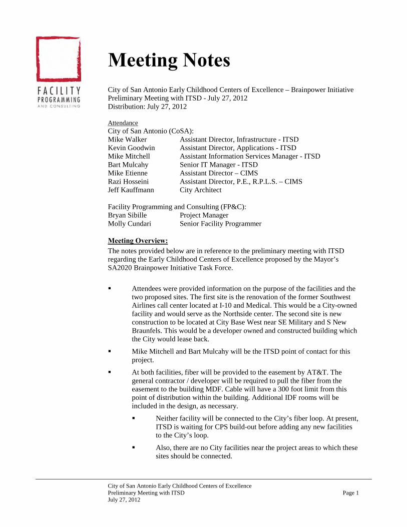
City of San Antonio Early Childhood Centers of Excellence Preliminary Meeting with ITSD Page 1 July 27, 2012
Meeting Notes City of San Antonio Early Childhood Centers of Excellence – Brainpower Initiative Preliminary Meeting with ITSD - July 27, 2012 Distribution: July 27, 2012 Attendance City of San Antonio (CoSA): Mike Walker Assistant Director, Infrastructure - ITSD Kevin Goodwin Assistant Director, Applications - ITSD Mike Mitchell Assistant Information Services Manager - ITSD Bart Mulcahy Senior IT Manager - ITSD Mike Etienne Assistant Director – CIMS Razi Hosseini Assistant Director, P.E., R.P.L.S. – CIMS Jeff Kauffmann City Architect Facility Programming and Consulting (FP&C): Bryan Sibille Project Manager Molly Cundari Senior Facility Programmer Meeting Overview: The notes provided below are in reference to the preliminary meeting with ITSD regarding the Early Childhood Centers of Excellence proposed by the Mayor’s SA2020 Brainpower Initiative Task Force. Attendees were provided information on the purpose of the facilities and the
two proposed sites. The first site is the renovation of the former Southwest Airlines call center located at I-10 and Medical. This would be a City-owned facility and would serve as the Northside center. The second site is new construction to be located at City Base West near SE Military and S New Braunfels. This would be a developer owned and constructed building which the City would lease back.
Mike Mitchell and Bart Mulcahy will be the ITSD point of contact for this project.
At both facilities, fiber will be provided to the easement by AT&T. The general contractor / developer will be required to pull the fiber from the easement to the building MDF. Cable will have a 300 foot limit from this point of distribution within the building. Additional IDF rooms will be included in the design, as necessary.
Neither facility will be connected to the City’s fiber loop. At present, ITSD is waiting for CPS build-out before adding any new facilities to the City’s loop.
Also, there are no City facilities near the project areas to which these sites should be connected.

City of San Antonio Early Childhood Centers of Excellence Preliminary Meeting with ITSD Page 2 July 27, 2012
Bart Mulcahy recommended that a Registered Communications Distribution Designer (RCDD) be engaged as early in the design process as possible to ensure the proper IT design (number and placement of rooms, cable distribution, etc.) and City standards are implemented in the building design.
Jeff Kauffmann stated that Brian Combs (Combs Consulting) is currently working with the City to develop new IT standards for construction and that he would be a good choice on this project.
Combs should be invited to the meeting with Debra Dockery, the design architect for the Northside center.
It was stated that bringing City fiber to the facility at City Base West, although nearby on the Brooks site, would be cost prohibitive. Also, since this building will not be City-owned it is not a good investment. Instead, the City will lease fiber from the provider.
To ensure that the facility still meets the City standards, ITSD will need to be involved with the Southside center developer. ITSD will give the developer the standards and design, as configured by the RCDD, which will be required to be in the facility.
Mike Walker raised concerns about quality control at the Southside center since this would be a developer-driven building. ITSD does not have the staff to manage the developer’s work for quality control on a daily basis, as may be necessary. Jeff Kauffmann and Razi Hosseini stated that it may be possible to provide oversight through one of the City’s on-call services.
ITSD data and cabling standards were discussed. They are currently in the process of being updated, although this is mainly related to the type of cable (CAT6) rather than the space, mechanical, and power requirements. Mike Mitchell will send FP&C the most current standards for inclusion in the program.
If server space is required by an outside entity, it would be preferable to include space for the rack(s) in the building MDF, rather than creating a separate closet.
The facilities will be provided with both wireless and hard-wired capability. This will allow the facilities to meet the unforeseen capacity/capability which may be required in the future as data needs change.
Offices and library computers will be hard-wired, as per standard.
Classrooms and building exterior will have wireless capability. A similar system was recently installed at Hardberger Park to create outdoor “classroom” learning environments.
A public address system may be required for this facility. One which has the capability to be multi-zone controlled is desirable. The PA will also need to have capability for broadcast on the building exterior and at playgrounds.
Budget constraints will determine how much technology is provided in the classrooms. At a minimum, conduit and infrastructure should be in place to support a wide variety of potential teaching equipment (i.e. overhead projectors).

City of San Antonio Early Childhood Centers of Excellence Preliminary Meeting with ITSD Page 3 July 27, 2012
Currently there are no standards for education technology at City facilities.
Kevin Goodwin noted that it would be good to understand what types of subscriptions and software applications may be required by the instructors in the library, training and classroom components.
Jeff Kauffmann stated that it is very early in the process and that the administration and staff who will be able to make these decisions have not yet been recruited.
A meeting is currently in the process of being scheduled, by Rebecca Flores in the City Manager’s office, with local teachers to discuss the preliminary space program and adjacencies. Kevin Goodwin stated that he would like to be involved at this meeting (tentatively scheduled for 8/8).
Derek Rabey will be the security consultant for this project. Mike Walker will coordinate a meeting with him regarding this project and the security requirements.
Mr. Rabey will assist the program and design team with identifying the requirements / location of security components in these facilities. Items to discuss will include electronic locks, prox cards, CCTV, intrusion alarms, panic buttons, etc.
Mr. Rabey will also assist in determining the location of security cameras.
RFID bracelets were discussed briefly as a potential method for tracking/controlling the movement of the children within the building.
Jeff Kauffmann briefly discussed the schedule for these projects. Money has been set aside for the construction of the facilities. The voters will vote in November on whether or not to increase the sales tax which would pay for the maintenance and operations. If the ballot passes, construction will begin in January 2013. It will be essential that as much of the ITSD design guidelines as possible are included in the program document and available to the architect and developer when the document is handed over at the end of August.
Next Steps
Mike Etienne is to contact the real estate broker to arrange for a walk-thru of the Southwest Airlines building with ITSD.
Razi Hosseini will schedule a meeting early next week with Debra Dockery to discuss the preliminary program information, adjacencies, etc. in advance of the meetings on 8/8 with Peter Zanoni and the local ISD teachers. Meeting will include FP&C, Jeff Kauffmann, Bill Hensley, and ITSD.
END OF MINUTES If any of the participants have any clarification, comments, additions or corrections to be made to these minutes, please submit them to Molly Cundari (email: [email protected]) within 3 business days.


City of San Antonio Early Childhood Centers of Excellence Local ISD Educator Meeting Page 1 August 8, 2012
Meeting Notes City of San Antonio Early Childhood Centers of Excellence – Brainpower Initiative Meeting with Local Educators – August 8, 2012 Distribution: Attendance City of San Antonio (CoSA): Rebecca Flores Education Policy and Services Administrator – City
Manager’s Office Bill Hensley Project Manager - CIMS Jeff Rodriguez Project Control Manager Andrea Salazar Intern – City of San Antonio Melody Woosly Department of Human Services Jessica Dovalina Department of Human Services Rhonda Roach Department of Human Services Local ISD Representatives: Pat Mesquiti Northside Independent School District Christa Carreno San Antonio Independent School District Erin Burnett San Antonio Independent School District Kathy Bruck Harlandale Independent School District Facility Programming and Consulting (FP&C): Bryan Sibille Project Manager Molly Cundari Senior Facility Programmer Meeting Overview: The notes provided below are in reference to the meeting with local educators regarding the Early Childhood Centers of Excellence proposed by the Mayor’s SA2020 Brainpower Initiative Task Force. A brief overview of the Brainpower Initiative was provided to attendees prior
to a review of the preliminary space list which had been developed with the City Manager’s office.
ISD’s typically have bus transport so the inclusion of a car seat storage is not typical. However, everyone agreed this was a nice amenity to offer.
Head Start programs often employ a behavior specialist who may utilize play therapy. Office space for contracted specialists has been provided in the space list. Educators noted that these individuals could also use a classroom for therapy, if available.
Discussion was had regarding the desire for a meditation or relaxation space where children who were frustrated or upset could be taken to relax and get their emotions under control. This would allow for the child to be separated from the rest of the class without causing further disruption. The Nurse Office may provide an opportunity for this to occur. The space could be

City of San Antonio Early Childhood Centers of Excellence Local ISD Educator Meeting Page 2 August 8, 2012
painted with soothing colors and have music, soft items (pillows), etc. to help calm the child.
The staff lounge / workroom had been proposed to be a single, multi-functional space. It is the preference that these spaces be separate areas or at least divisible by a half-wall.
The lounge is intended more for dining and to provide kitchen/food prep/storage capability to the staff than for relaxation of the employees.
The workroom will contain items such as laminators, copiers, die-cut machines, printers, employee mailboxes, etc.
Classroom cabinets should have the capability to be locked. Upper and lower cabinets are desirable for additional storage.
A Head Start classroom is required to be 800SF. When calculating the square feet, anything which can be moved and is not fixed may be counted in the floor area.
Display space should be provided in classrooms at children’s eye and reach level.
A sink at the food prep area in the classroom is preferable. A butler’s pantry would be a nice concept to allow for the delivered and empty food trays to be stored out of the way.
Tables for four – round or square – with color tops are desired in the classroom. These could also be used for different centers / learning experiences.
Area for the large group to gather is necessary. This may also be used for naptimes. Rugs (9x12, 12x12) should be placed on the floor to create designated areas for reading, nap, etc.
Yoga mats are being utilized for naps (1 per child) due to the minimal amount of space which they require for storage.
The various types of learning centers within classrooms, based on curriculum, were discussed. Both static and dynamic centers were also discussed.
Static centers – house, block, book/library, art and sensory (sand/water)
Dynamic centers – toy, science, computer/technology (laptops / iPads), discovery area
The use of mobile furniture was encouraged for maximum flexibility
There should be no playscapes located in the classrooms. Outdoor playscapes are preferred.
Classrooms should have technology such as overhead projectors, Smartboards, etc.
Teachers do not need a dedicated work area as long as there is a space for a laptop and storage of their personal items. Assistants will

City of San Antonio Early Childhood Centers of Excellence Local ISD Educator Meeting Page 3 August 8, 2012
also need an area for personal item storage. It is possible to use built-in cabinetry as a worksurface for the faculty.
Security cameras are not desired in the classroom. Since the classrooms are intended to be model “lab” environments, viewing of the class activities from the hallway is desirable.
The children’s restroom does not require a diaper changing area.
The lobby should feel more like a living room setting. Consider providing a play area for the children, like in a doctor’s office. In addition, an exhibit area may be set up in the lobby to allow for the showcasing of 1 or 2 classrooms as rotating exhibits throughout the year.
No panic button is necessary at the lobby. A PA system could be used in case of emergency notification.
Hallways and corridors could be utilized for display area of children’s artwork and classwork. This should be at the children’s level. Observation windows in classrooms would then be located 4’-0” above floor level to accommodate.
It would be ideal to have a family resource room.
The Nurse Office bathroom should have a shower to allow for clean up of children who have accidents during the class day.
Teachers should have the capability to receive voicemail. It is not necessary for each to have a telephone, but a voice mailbox would allow for them to receive messages from parents, etc.
Playgrounds should have a variety of playscape choices and have areas with shade. Consider also the use of sidewalk area for chalk art, riding tricycles, etc. Design may incorporate the walk to the playground into a learning experience, as well. Consider the utilization of “natural” playground experiences (i.e. berms).
The idea of utilizing RFID badges to maintain track of the children was discussed and generally opposed by the educators.
END OF MINUTES If any of the participants have any clarification, comments, additions or corrections to be made to these minutes, please submit them to Molly Cundari (email: [email protected]) within 3 business days.


City of San Antonio Early Childhood Centers of Excellence East and Westside Center Program Review Page 1 May 9, 2013
Meeting Notes City of San Antonio Early Childhood Centers of Excellence – Brainpower Initiative East and Westside Center Program Review Meeting – May 9, 2013 Distribution: May 14, 2013 Attendance City of San Antonio (CoSA): Kathy Buck Interim CEO, Pre-K 4 SA Sandy Chevarria Center Director, Pre-K 4 SA Bill Hensley Project Manager - CIMS Facility Programming and Consulting (FP&C): Molly Cundari Senior Facility Programmer Meeting Overview: The notes provided below are in reference to the meeting with Pre-K 4 SA administration regarding the program for the East and Westside Early Childhood Centers of Excellence proposed by the Mayor’s SA2020 Brainpower Initiative Task Force. The draft program for the East and Westside Centers was presented and
lessons learned were discussed for inclusion in the final program document.
Natural light in the classrooms was discussed at length. The program for the new centers “requires” natural light in classrooms rather than “desired”, as in the previous center programs.
The North and Southside Center program document was utilized as the basis for the program for the two new proposed centers. A third training room was added to the program document for additional professional development space, as well as to provide an area for scheduled school activities, such as pre-K student graduation ceremonies, plays, etc.
Several revisions to the draft document were discussed during the meeting and have been included in the final document. They are as follows:
Consider utilization of a visitor management/registration system (ie. Raptor Security System or similar) to protect the students, faculty, and visitors at schools. Such systems enhance school security by reading visitor driver’s licenses, comparing information to a sex offender database, alerting campus administrators if a match is found, then (assuming no match was made) printing a visitor badge, which includes a photo.
Door hardware on exterior doors within classroom zone shall be equipped with alarm to alert instructors / staff of unauthorized use. Doors shall be provided with key-override for use by instructors or administration staff.

City of San Antonio Early Childhood Centers of Excellence East and Westside Program Review Page 2 May 9, 2013
Consideration to be given to installation of a visual intercom system (ie. Aiphone or similar) at main entry which will allow for Receptionist to view guest and control access to the building.
Provide intercom system in classroom which allows instructor to page a nurse or administrative staff in case of emergency.
Designation of Teacher’s Storage Closet as “Walk-In”.
Added (1) private office @100SF for use by Pre-K 4 SA staff (housed at the Southside Center) when conducting site visits or at the center for scheduled events/meetings. Office will be located within the center director’s administrative suite.
Addition of Table / Chair Storage @100 SF near the Training Rooms.
Addition of Classroom Supply / Bulk Materials Storage @100 SF.
The desire for a cafeteria function to be included in the new centers was discussed. It was decided that this function will not occur in the new centers and meals will continue to be served in the classroom, family style.
Playground design was briefly discussed. Administrators have moved away from the installation of swingsets in the playground design due to child safety concerns. Utilization of “natural” playground experiences (i.e. berms) was also discussed. Considerations for such playground design amenities had already been included in the draft program.
END OF MINUTES If any of the participants have any clarification, comments, additions or corrections to be made to these minutes, please submit them to Molly Cundari (email: [email protected]) within 3 business days.

BAppendix


SA2020 Brainpower Initiative Task Force
Prepared for Mayor Julián Castro, Task Force Co-Chairs USAA CEO Maj. Gen. Joe Robles and H-E-B Chairman and CEO Charles Butt and the Brainpower Task Force
Members
By Gillian Williams, President The Rensselaerville Institute
May 29, 2012

1
Table of Contents
Introduction ....................................................................................................................... 2 Executive Summary .......................................................................................................... 3 Brainpower Investment Strategy ..................................................................................... 5 Financing ......................................................................................................................... 12 Governance ..................................................................................................................... 15 Appendices ...................................................................................................................... 21

2
Introduction In May 2011, Mayor Julián Castro assembled a committee of concerned business and education leaders to determine if a targeted, significant financial investment could fundamentally improve San Antonio's educational trajectory. The group, led by USAA CEO Maj. Gen. Joe Robles and H-E-B Chairman and CEO Charles Butt, was evenly split between business leaders and education experts, including area school superintendents and college presidents. They examined three areas — very early childhood education, dropout prevention and college attainment. After more than a year of studying best practices and evidence-based outcomes in other U.S. cities, the data was incontrovertible. When children enter kindergarten prepared to learn, they are more confident and apt to succeed throughout their academic career, while teachers and administrators are freed from the burden of teaching and crafting curriculum to students with varying levels of preparedness. There are more than 20,000 four-year-olds in San Antonio today. Through circumstances that have nothing to do with their intelligence or capacity to learn, one in four of those children who are otherwise eligible for state and federally funded pre-K either go unserved or receive just a half-day of early education. They are eligible because of their income, their home language, their parents’ military participation or time spent in the foster care system. Not only do these children miss out on the full benefits of early childhood education, area school districts leave between $10 million and $11 million dollars in state funding — more than $2,500 per child — on the table. Catching these students up is an additional drain on the system. In order for San Antonio to build a globally competitive workforce that is prepared to take on the jobs of the 21st century, the Brainpower Committee determined that San Antonio could yield the most profound results across the education spectrum by starting early. A 1/8-cent sales tax, to be voted on by San Antonio voters on Nov. 6, 2012, will generate an estimated $29 million annually and be eligible to draw down matching state funding of between $10 million and $11 million. The cost of this investment is estimated to be $7.79 annually per median San Antonio household.

3
Executive Summary The Brainpower Initiative Task Force, envisioned by Mayor Julián Castro and co-chaired by USAA CEO Maj. Gen. Joe Robles and H-E-B Chairman and CEO Charles Butt, will be recommending to the Mayor and City Council a ballot measure for the use of the 1/8-cent sales tax on November 6, 2012. The Brainpower Task Force has chosen Early Childhood Education across San Antonio as its area of focus. It is anticipated that this initiative will generate an estimated $29 million annually. It will also be eligible to receive matching state pre-Kindergarten dollars estimated at between $10 million and $11 million annually. The measurable outcome for this initiative will be to dramatically and sustainably raise achievement for the children of San Antonio as measured by the third grade state tests in reading and mathematics. What differentiates this investment is that it will be in results for the children of San Antonio – not simply funding of more programs. There will be common milestones for clearly measuring progress each year so that everyone in the city knows what is being achieved. Providers who do not achieve results will be supported in course corrections and disinvested, if necessary. The Task Force has determined that the best investment is in pre-K education. There are about 20,000 4-year-olds in San Antonio, 16,000 of whom are eligible for half-day pre-K under state and federal guidelines (factors include income, language, foster care settings, and military families). One-quarter of these eligible children are not currently being served in full-day kindergarten. If approved, this initiative will invest in a three-part strategy to serve 4,500 annually, with a focus on those who are at risk of not being prepared to hit the ground running in kindergarten. It will serve an estimated 19,275 children over 5 years. The strategy includes:
1. Establish two world-class early learning centers that serve 700 children and model best practices. In subsequent years, develop additional exemplary centers to serve an additional 800 children. Participating students will be chosen through a lottery.
2. Raise student achievement in existing pre-K classes through citywide capacity-building and support for all pre-K teachers to create a highly capable pre-K workforce that consistently demonstrates effective teaching of young children.
3. Serve an additional 3,300 4-year-olds who are eligible under state and federal guidelines but not currently enrolled in full-day pre-K, and incentivize providers to serve an additional 500 children through a sliding scale. (800 of those 3,300 will be served in model centers in later years.)
The data is clear. The best investment in America to improve educational outcomes is pre-K education. Research at the University of Wisconsin found that an average of $6,730 invested in early education saved $47,759 by eliminating or reducing expenses associated with remediation, unemployment and incarceration.

4
In Dividends of Early Learning, Arthur Reynolds shows that attendance in pre-K leads to: • 29% increase in graduation rate for at-risk children; • 41% reduction in later placement rates in special education; • 40% less likelihood of being retained in one or more grades.

5
THE BRAINPOWER INITIATIVE INVESTMENT STRATEGY

6
San Antonio Brainpower Initiative Pre-K Investment Strategy This strategy will leverage state funding and existing Head Start models — and in doing so promote a more consistent, community-wide emphasis on outcomes for pre-K in school districts, among independent providers and through Head Start. This initiative will supplement the state/federal funding that covers half-day pre-K with the express purpose of providing high quality full-day pre-K. In order to receive funding, districts and providers must commit to clear targets for achievement and reporting on how students do in relation to these targets. Students will focus on developmental milestones for reading (literacy) and math (numeracy) that put them on track for a high degree of academic success at annual intervals. Specific Areas for Investment Include:
1. Establish two world-class early learning centers that serve 700 children and model best practices. In subsequent years, develop additional exemplary centers that serve an additional 800 children. Total number of children served expected to climb to 4,500 between these model centers and other partners by 2015. Over the five year course of the sales tax, the initiative is estimated to serve 19,275 4-year-olds in pre-K education.
• Highly qualified and innovative leaders will be recruited to design and lead the model centers. These leaders will bring the innovative and entrepreneurial outlook needed to take these schools to the top of the nation’s premiere pre-K education settings.
• In Years 3-5, other centers throughout the city that have demonstrated success through the initial investment and a commitment and capacity for high achievement will be eligible for additional investment to become model centers themselves.
• Teachers for the model centers will be recruited and trained through a highly rigorous process. Teachers and leaders will receive an additional stipend for leading the professional development of other teachers who will take best practices back to their home school districts.
• Investment at the model centers will be $6,500 per child and include additional family support services. Total per child funding, in conjunction with state investment, will be approximately $9,200 per child.
• Investment in Years 3-5 for centers who commit to replicating key elements of the model centers will be at $5,000 per child and in conjunction with state funding will total $7,700 per child.

7
Pre-‐ Kindergarten Expansion Schedule
Year # of Students per
Year # of Students in Model Centers
# of Students in Added Slots
# of Students for Sliding Scale
2013 1,275 700 500 75 2014 4,500 700 3,300 500
2015-‐2017 4,500 1,500 2,500 500 Five Years Total 19,275 5,900 11,300 2,075
2. Raise student achievement in existing pre-K classes by creating a highly capable
pre-K workforce that consistently demonstrates effective teaching.
• The two model centers will serve as learning labs for ongoing professional development for teachers throughout the city. The initiative further leverages the high quality classrooms and teachers by providing training and development through exemplary models and master teaching.
• Citywide training for all existing pre-K teachers with a focus on creating classrooms defined by strong reading (literacy) and math (numeracy) learning and development of lifelong learning skills.
• Institute a common citywide assessment that provides teachers and families the information needed to provide quality learning experiences and course correct the teaching and learning process.
3. Serve the remaining eligible children with high-quality, full-day pre-K, and incentivize providers to serve an additional 500 children through a sliding scale.
• Children who are eligible for state pre-K or Head Start will be the primary focus of this investment. This is the area of greatest need and it allows for state and federal funding to be leveraged.
• All districts and vetted partner-providers will be eligible for supplemental investments to match state-sponsored pre-K funds in order to provide full-day pre-K. Investments may not be used by districts as a substitute for existing funding (however they will be eligible for expanding half-day to full-day).
• Sliding scale options will be incentivized so that parents who might not be able to access full-day accredited pre-K will now be able to do so. Providers will receive some funding support to do so and those providers who make sliding scale space available will receive extra consideration for funding.
• Investment at traditional centers and schools will be at $4,000 per child for the first year (includes classroom set-up costs) and at $3,500 for subsequent years. In conjunction with the state funding this will result in approximately $6,700 per child for the first year to include start-up costs and drop to $6,200 for subsequent years.
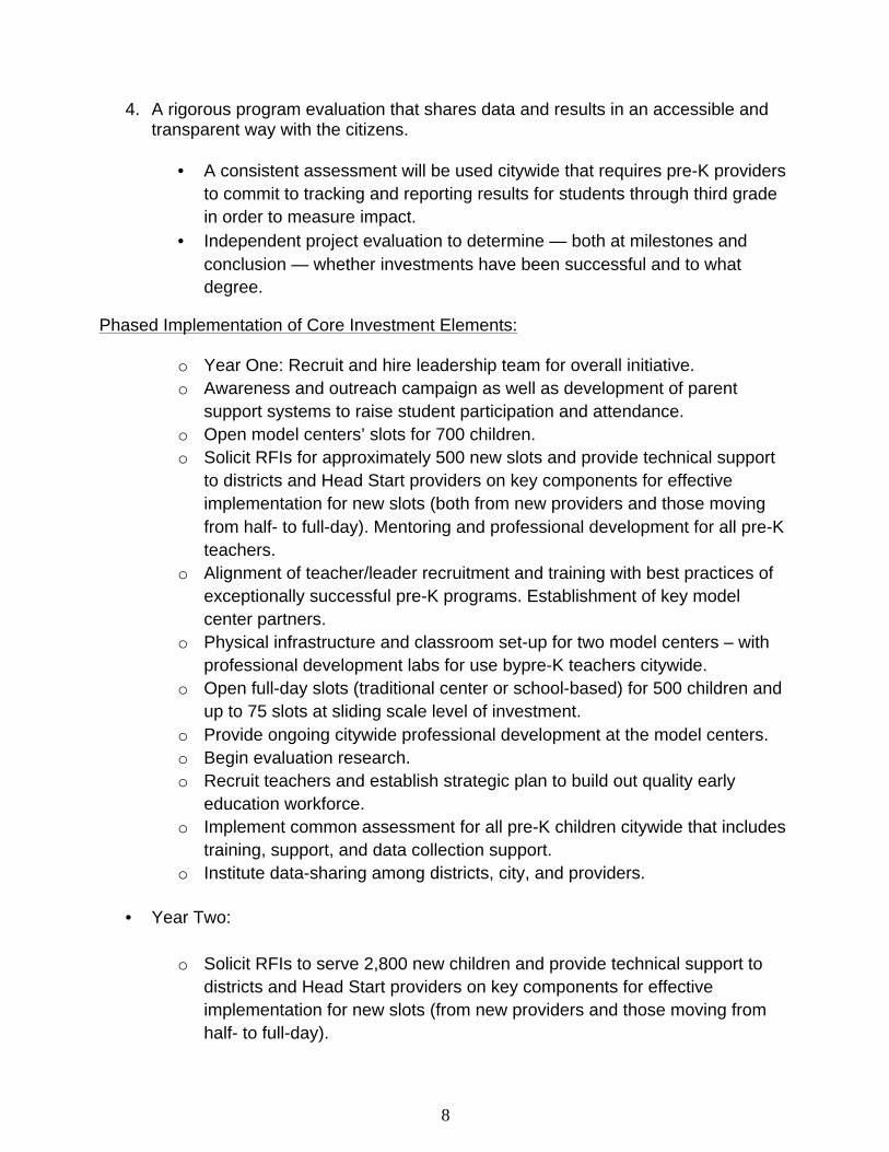
8
4. A rigorous program evaluation that shares data and results in an accessible and transparent way with the citizens.
• A consistent assessment will be used citywide that requires pre-K providers to commit to tracking and reporting results for students through third grade in order to measure impact.
• Independent project evaluation to determine — both at milestones and conclusion — whether investments have been successful and to what degree.
Phased Implementation of Core Investment Elements:
o Year One: Recruit and hire leadership team for overall initiative. o Awareness and outreach campaign as well as development of parent
support systems to raise student participation and attendance. o Open model centers’ slots for 700 children. o Solicit RFIs for approximately 500 new slots and provide technical support
to districts and Head Start providers on key components for effective implementation for new slots (both from new providers and those moving from half- to full-day). Mentoring and professional development for all pre-K teachers.
o Alignment of teacher/leader recruitment and training with best practices of exceptionally successful pre-K programs. Establishment of key model center partners.
o Physical infrastructure and classroom set-up for two model centers – with professional development labs for use bypre-K teachers citywide.
o Open full-day slots (traditional center or school-based) for 500 children and up to 75 slots at sliding scale level of investment.
o Provide ongoing citywide professional development at the model centers. o Begin evaluation research. o Recruit teachers and establish strategic plan to build out quality early
education workforce. o Implement common assessment for all pre-K children citywide that includes
training, support, and data collection support. o Institute data-sharing among districts, city, and providers.
• Year Two:
o Solicit RFIs to serve 2,800 new children and provide technical support to
districts and Head Start providers on key components for effective implementation for new slots (from new providers and those moving from half- to full-day).

9
o Serve 2,800 new children and an additional 425 children with a sliding scale, bringing total children served to 3,800, of which 500 are sliding scale.
o Continued investment in model centers for 700 children. o Ongoing outreach and support for parents to emphasize importance of pre-
K and increase participation and attendance. o Mentoring and ongoing professional development for all pre-K teachers and
leaders that is focused on raising student achievement at model centers o Ongoing classroom materials and supplies. o Ongoing investment in common assessment for all pre-K children citywide
that includes training, support, and data collection.
• Years Three to Five:
o Investment in additional high-performing centers who replicate model-center approach for up to 800 children of the 3,800 children currently funded (with option for up to 120 of the 500 at sliding scale children to participate).
o Technical support to districts and Head Start providers willing to implement high-quality model-centers model.
o Ongoing outreach and support for parents to emphasize importance of pre-K and increase participation and attendance.
o Technical support to districts and Head Start providers on effective early education implementation strategy.
o Mentoring and ongoing professional development for all pre-K teachers and leaders that is focused on raising student achievement.
o Ongoing classroom materials and supplies. o Continued investment for up to 3,300 children in full-day pre-K, including up
to 500 children at sliding scale level of investment. o Continued investment in model centers for 700 children. o Ongoing citywide professional development at the model centers. o Ongoing investment in common assessment for all pre-K children citywide
that includes training, support, and data collection.
Predictive Success Factors and Indicators Rather than design a set of activities and best practices, it’s important to know what factors will predict success for this investment — and to tie the investment to these predictive factors. The research converges on four core areas that predict success in kindergarten readiness and sustained success through elementary school:
• An academic/cognitive approach with a specific focus on literacy (reading) and numeracy (math).
• Rigorous expectations for staff around professional development.

10
• Clear data use for informing decision-making and course correction. • Parent/Primary caregiver involvement and support for learning.
Academic: These are the key areas that most impact student achievement and when they are effectively dealt with early lay the groundwork for later success in school. They most connect to what students will need in the future when entering the workforce. Emphasis on these areas also differentiates pre-K from daycare. Key to the approach here is what is developmentally appropriate for learning versus a checklist of isolated skills.
• Core literacy and numeracy standards for learning that will match what students need to be kindergarten ready at a high level of competency (equivalent of “commended” level).
• Pre-K students will spend their classroom time engaged in activities that develop core literacy and numeracy skills.
• Pre-K students will develop skills that focus on application of knowledge. • Students need the key habits and emotional capacity (such as persistence and
the ability to regroup) that are tied to long-term success in school. Expectations for Staff: Understanding the key developmental curricular issues. What to teach and how to teach it requires a massive training undertaking that requires ongoing support. This requires teachers and school leaders getting on the same track for an effective pre-K teaching approach. The emphasis needs to be on what’s critical, not on being comprehensive.
• Capacity to teach and facilitate literacy- and numeracy-based activities and the development of a print- and language-rich learning environment.
• Capacity to administer, analyze and use formal and informal assessment protocols that are tied to literacy and numeracy. All teachers will use the information to inform instruction and move children along the continuum of learning.
• Foster children’s emotional well-being with regard to the link between this and learning for 4 year-olds.
• Create enriched learning environments where children apply concepts and skills in a variety of contexts.
Clear Data Use: The distinction here is around purpose. Effective data use isn’t about evaluation of a program but rather the information that teachers get that enables them to plan for learning and course correct along the way. Assessments that provide checkpoints for developmental milestones and understanding give teachers the information they need to improve student performance.
• Teachers and leaders will use a common assessment citywide to track individual and cohort data in ways that inform how they adapt and course correct the teaching and learning process at regular intervals.
• All participating pre-K students will take a common citywide assessment that assesses high-level skills and is used to benchmark progress.

11
• All kindergarten students citywide will take the common assessment. • Continued tracking of students in all participating institutions/ISDs.
Parent Engagement: Attendance and participation in pre-K programs relies more heavily on the comfort-level of parents and ease of access than K-12. Parents who fully understand the importance of pre-K learning to their child’s later success in life are much more likely to reduce absenteeism, invest in transition to kindergarten, and support child learning at home.
• Enrollment of 4-year old children in pre-K. • Full-day, on-time attendance. • Family engagement that is tied to supporting attendance and learning. • Family reading with children for 20 minutes every day.

12
Governance and Leadership
Enabling Legislation NOTE: In the language of the enabling legislation, “corporation” refers to the organization that will be created to lead the Brainpower Initiative. “Governing municipality” refers to the City of San Antonio government – specifically The Office of the Mayor, The City Manager and the City Council. The governing municipality will create the corporation. The initial bylaws and any subsequent bylaw amendments must be approved by the governing body of the municipality. Additionally, the enabling legislation is clear that the board members must be appointed by the City Council and no board members may be an employee of the city. The board must undergo a performance review every five years but submit an annual report each year specifically on results achieved. The budget for the corporation must be presented to the governing body. Board Composition The City Council will appoint board members. The recommendation to the City Council will be that some members of the Brainpower Initiative Task Force be considered as founding board members. This will provide continuity during the time of transition from strategy to execution. The board members who are recommended to the City Council for appointment will need to consider strong city-wide geographic representation. Organizational Leadership For the initial operationalization of the strategy will need a strong interim leader. This will need to be someone with a strong results focus who understand the tenets of the strategy and has the execution skills necessary to both develop the clear tactics, protocols, tools, and organizational systems that will bring this initiative to life – and clarify for the public via the campaign what it will actually look like. A search must be conducted for someone who has the skill-set and energy to lead this initiative. Someone with a track record of entrepreneurship and innovation will be critical. In addition, with the city’s move toward a collective impact approach this leader will need to have the ability to create a common agenda for a number of different partners. Model Centers: Governance and Leadership These centers need to be the beacons of possibility and opportunity for the City of San Antonio when it comes to children embarking on an exemplary education. As such, they should not be attached to any one entity but rather remain as a clear part of the Brainpower Initiative. The two model centers must be supported fully by many partners in the city in order to reach world-class status – and they must also be able to operate autonomously and free from the traditional restrictions of regulations for schools. The leader of the organization will recruit and hire highly qualified and innovative leaders to design and lead the model centers. These leaders will bring the innovative and

13
entrepreneurial outlook needed to take these schools to the top of the nation’s premiere pre-K education settings. A Memorandum of Understanding will be crafted with the 15 San Antonio school districts which will take into consideration the varying levels of state per-pupil funding and varying teacher salaries across the districts so that all public school district students and teachers can participate at an equal level.

14
Brainpower Initiative Board of Directors
Office of the Mayor City Council
Model Centers Added High-‐Quality, Full-‐Day Pre-‐K Slots Capacity-‐Building for Pre-‐K Educators
Director – Center One
Director – Center Two
Center One All Staff
Center Two All Staff
University Partners
Professional Development Team Embedded at Model Centers
External Providers
Brainpower Initiative Executive Director
Programs and Assessment Staff
Administration Staff
Program and Technical Support to Providers
Accountability of Providers
Providers
City Manager
BRAINPOWER INITIATIVE – DRAFT ORGANIZATIONAL CHART

15
Budget Outline for Major Investment Components YEAR ONE Awareness and Outreach Campaign – including recruitment of students
$1,500,000
Model Centers – Development and Set-Up $2,000,000 Model Centers – 700 slots @ $6.5k/child $4,550,000 New Slots (provider-based, full support) – 500 slots @ $4k/child $2,000,000 Sliding Scale Slots – up to 75 slots @ average $2k/child $150,000 Educator Recruitment, Training, Development $5,000,000 Common City-wide Assessment and Data Use $4,500,000 Initiative Leadership and Administration $1,000,000 Research and Evaluation $500,000 TOTAL $21,700,000 YEAR TWO Ongoing Awareness and Outreach Campaign $1,000,000 Model Centers – 700 slots @ $6.5k/child $4,550,000 Model Centers – Continuous Support $1,000,000 New Slots (provider-based, full support) – 2,800 slots @ $4k/child $11,200,000 Ongoing Slots (provider-based, full support) – 500 slots @ $3.5k/child $1,750,000 Sliding Scale Slots – up to 500 slots @ average $2k/child $1,000,000 Educator Training and Development $4,700,000 Common City-wide Assessment and Data Use $4,000,000 Technical Assistance to Providers $600,000 Initiative Leadership and Administration $1,000,000 Research and Evaluation n/a TOTAL $30,800,000 YEARS THREE THROUGH FIVE Ongoing Awareness and Outreach Campaign $250,000 Model Centers – 700 slots @ $6.5k/child $4,500,000 Model Centers – Continuous Support $500,000 Model Center Replication – 800 slots @ $5k/child $4,000,000 Ongoing Slots (provider-based, full support) – 2,300 slots @ $3.5k/child
$8,750,000
Sliding Scale Slots – up to 500 slots @ average $2k/child $1,000,000 Educator Training and Development $4,700,000 Common City-wide Assessment and Data Use $4,000,000 Technical Assistance to Providers $500,000 Initiative Leadership and Administration $1,000,000 Research and Evaluation n/a TOTAL 26,200,000 TOTAL OVER FIVE YEARS: $140,100,000
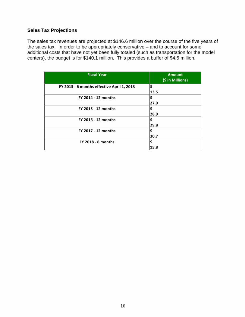
16
Sales Tax Projections The sales tax revenues are projected at $146.6 million over the course of the five years of the sales tax. In order to be appropriately conservative – and to account for some additional costs that have not yet been fully totaled (such as transportation for the model centers), the budget is for $140.1 million. This provides a buffer of $4.5 million.
Fiscal Year Amount ($ in Millions)
FY 2013 -‐ 6 months effective April 1, 2013 $ 13.5
FY 2014 -‐ 12 months $ 27.9
FY 2015 -‐ 12 months $ 28.9
FY 2016 -‐ 12 months $ 29.8
FY 2017 -‐ 12 months $ 30.7
FY 2018 -‐ 6 months $ 15.8

17
Tax dollar revenues
City Manager’s Office
Brainpower Initiative Organization
Model Centers
Professional Development Providers
Providers of Added Slots
Assessment & Data Use Support
Evaluation Partner
Parents (Non-‐Eligible Sliding
Scale)
Districts Districts
Parents (Non-‐Eligible Sliding
Scale)
State ADA Funds per Student
Teacher Salaries
Brainpower Initiative – Funds Flow Analysis

18
Assessment of Applicants and Investees Key Questions to Determine Qualifications of Potential Providers
1. Do key people have the attributes and capabilities that predict success? 2. Is prior achievement strong in most relevant work of the provider? 3. Is the provider clear in terms of needed intensity/duration to make a difference in
their approach/services? 4. Is “cost for human gain” strong compared to similar approaches/providers? 5. Has the provider clearly tracked data to show success? And better still, used it to
make changes? 6. Are there strong project level impact potentials beyond specific results? 7. Are there reasonable impact possibilities or replication that goes beyond the
project? Key Questions for Those Requesting Investment To learn what the result is projected to be:
1. Define the mix of children with whom you will work in terms of degree of difficulty in getting to school readiness and third grade school achievement.
2. Of the four-year-olds with whom you will work, how many will arrive at kindergarten ready to learn as measured by the citywide assessment?
3. Given the specific population with which you propose to work, how many children do you project would arrive ready without your program versus with it?
4. Of the four-year-olds you look to serve how many will you be willing to bet on reaching grade level in third grade literacy and numeracy?
To determine chances the result will be achieved:
1. What is the level of past success of the applying group in achieving results in this area?
2. What are the most critical points of approach or any other factor you see as critical in your program to achieve results?
3. Who are the key people who will lead your program and interact with children to achieve results
4. How will you know whether you are on track to deliver the results to which you are committed?
Key Questions for Interim Reports
1. Are you serving the same mix of children with regard to degree of difficulty in getting to school readiness and third grade achievement as you defined in your plan? If not, how has that mix changed?
2. Are you on track to achieve stated results with the time and money remaining? 3. If not, please tell us how far off course you are regarding time and/or money? 4. If you are off course please state the reasons and tell us what you are doing to get
back on course.

19
Tracking Provider Progress with Benchmarks and Milestones Overall Benchmarks for Participating Children and Programs
• Benchmark 1: 90% of children are kindergarten-ready as evidenced by citywide assessment results.
• Benchmark 2: Participating children show gains of 15% over non-participating children at the end of kindergarten.
• Benchmark 3: Participating children show an increase of 10% over non-participating children on the third grade STAAR assessment.
Academic Indicators with Milestones
• Milestone: 90% of children who received two or more assessments will meet the development and learning expectations for their age range on the designated assessment.
• Milestone: Children will spend 80% of their time in school engaged in literacy and numeracy activities – particularly those where they apply knowledge in various contexts (including alternate times such as lunch, art, etc).
• Milestone: 100% of classrooms will provide explicit support and instruction for the core habits and emotional capacity that is tied to long-term success in school.
Assessment and Data Use Indicators with Milestones
• Milestone: 100% of teachers and leaders will effectively support the implementation of the citywide direct assessment at 2-3 intervals annually and use the data to inform teaching and learning decisions
• Milestone: 100% of teachers will effectively implement the citywide weekly student observation assessment – and use it to course correct where students fall short on expected quarterly milestones
• Milestone: 100% of program classrooms will participate in an initial program assessment each year. Program classrooms who received a score less than exemplary will engage in a second program assessment that year.
• Milestone: 100% of all teachers and leaders attend the citywide training on assessment administration and data use and achieve a level of competency in understanding how to interpret and use data to make changes in the classroom.
• Milestone: All leaders/directors/principals will implement a clear system to use the information from assessments to inform and adapt instruction and increase student learning.
• Milestone: 100% of providers will track children in accordance with the citywide data-sharing plan
Teacher/Leader Quality Indicators with Milestones
• Milestone: 100% of all pre-K teachers and leaders will participate in the professional development provided citywide on the core skills around teaching literacy and numeracy and applied learning as well as on supporting key habits such as persistence and perseverance that are linked to long-term success in school.

20
• Milestone: 100% of leaders will provide feedback weekly to each teacher specifically on the effectiveness of literacy and numeracy learning in the classroom. All feedback will be constructive and useful for teacher growth.
• Milestone: 100% of teachers will actively participate in 8 hours of coaching or support per month on literacy/numeracy teaching and learning strategies by a mentor or the citywide professional development at the model centers.
• Milestone: 100% of providers will support teachers through mentoring and professional learning communities
• Milestone: 100% of teachers will provide kindergarten transition information on each child for the receiving kindergarten school.
• Milestone: 100% of programs will have a clear kindergarten transition support plan for students and families that involves pre-K and K teachers.
Family/Caregiver Indicators with Milestones
• Milestone: 90% of total slots will be enrolled by October 1 • Milestone: 90% attendance for first quarter; 95% for subsequent quarters • Milestone: Intervention and development of an attendance plan for family behavior
change with 100% of non-compliant families • Milestone: 95% of parents will attend initial sessions and receive clear
expectations and training around attendance and reading at home. • Milestone: The teacher (or outreach worker/designee) will meet with 100%
children’s parents or guardians at least two times annually to discuss the child’s development and jointly plan school and home strategies to support the child’s success. She/he will also keep parents up to date on assessment results and any special needs issues that arise from additional assessment.
• Milestone: School/agency will identify children with learning, mental/physical health and other developmental challenges and develop and implement an intervention plan in collaboration with the child’s family.
• Milestone: 90% performance with documenting/reporting at-home reading. • Milestone: 100% of students will be registered on time for kindergarten

21
APPENDICES

22
APPENDIX A: Model Centers The key to effective model centers is that the right leaders be established for each of them. These leaders will need to bring qualities that reach beyond those of leaders who lead strong, established schools. They will need to bring the innovative and entrepreneurial outlook needed to take these schools to the top of the nation’s premiere pre-K education settings. A host of resources and expertise from San Antonio and around the country will be assembled for these leaders to draw on for the range of critical areas – from curriculum model to recruitment of master teachers to facilities. One such expert, Dr. Ellen Frede was called upon to delineate the key program elements of effective pre-K that need to be considered and then examined and elevated to exemplary level. Program Elements (developed for Brainpower Initiative by Dr. Ellen Frede, May 2012) In most early learning initiatives program standards are defined as those static program features that are necessary but not sufficient to ensure high quality practice, such as class size, length of day, curriculum and assessment tool adoption, or teacher qualifications, as opposed to dynamic aspects of quality such as teacher-child interaction, how well the curriculum model is implemented or relationships with parents.
b) Organization and size: Keep class size as close to 15 as possible given resources. Incorporate methods for adjusting the techniques used in the model classrooms for less ideal circumstances into the professional development plan for external programs.
c) Facility: Organize classrooms in a “pod structure” of 4-5 pods of five classrooms
each. Ideally, in the facility design and footprint, each of the pods would have a separate playground and indoor gross motor area. There should not be a cafeteria in the facility, as Head Start regulations and best practice require in-classroom “family style” meals which facilitate teaching self-help skills, social skills and reinforcing learning through informal conversation. Incorporate child bathrooms and storage closets shared between two classrooms.
d) Staffing: Each classroom should be staffed with one teacher certified to teach pre-
K and one assistant teacher with an AA in early childhood education, both should be bilingual. Among the teachers, shared expertise can raise the level of education in each domain, thus, at least one teacher should have an interest in each of the following: drama, mathematics learning, dance, science education, the visual arts, the environment, parental engagement, children’s literature, and music.
e) Curriculum: Implement a different curriculum model in each pre-K model center. Professional development will be easier but at the same time collaborating programs have at least two models from which to choose.

23
f) Inclusion practices: Place children with disabilities in the regular classroom with appropriate supports and modifications. As much as possible ensure that the proportion of children on IEPs in an individual classroom mirrors the proportion in the population (i.e. If 10% of the pre-K population served has an IEP then no more than 10% of the children in an individual classroom should be on an IEP.) Ensure that all staff members have appropriate training, demonstrated capacity, and support to meet all children’s needs.
g) Scheduling options: Provide extended-day and extended-year services and
access child care subsidy dollars. Staff extended-day as a child care center with staff meeting only those qualifications required by child care licensing. In the summer, operate at least one pod for at least one month to allow for these classrooms to be used as practice sites for summer in-service for collaborating programs.
h) Establishing pre-K advisory councils: Form a pre-K advisory council for each
model center to enhance community partnerships.

24
APPENDIX B: Assessment Strategy Teachers and leaders will use a common assessment citywide to track individual and cohort data in ways that inform how they adapt and course correct the teaching and learning process at regular intervals. A common measure allows for consistent professional development and technical assistance for educators; ability to evaluate effectiveness of initiative and is most cost-efficient. For the Brainpower Initiative the assessment strategy will:
• Purchase pre-K-2 assessment that requires multiple data points. This will entail both direct assessment at 2-3 intervals as well as observation and checklist formative assessment.
• Provide additional support for administration, observation, scoring and analysis. This support will entail trained people who will undertake administration of actual direct assessments with children. Additionally, the scoring and initial analysis will also be handled as part of the support provided.
As part of this strategy:
• All participating pre-K students will take a common citywide assessment that assesses high-level skills and is used to benchmark progress
• All participating teachers will track student progress with ongoing assessments and course-correct based on what the data shows
• All kindergarten students citywide will take the common assessment • Assessments will be provided in English and Spanish • Program assessment in addition to child assessment (with the concept that the
program/classroom predicts student learning and should be considered in conjunction with individual student assessment)
Types of Pre-K Assessments Direct Assessment: a norm or criterion referenced assessment that is given at a specific time and in specific ways. They may be administered 1-3 times per year. This provides strong comparative data and allows teachers to get a lot of information. Observational Assessment: teachers use checklists and observational protocols for watching children conduct authentic work in the classroom. These are used frequently and over time with information being collected in a variety of reporting tools. Program Assessment: measure the educational experiences that the programs and classrooms that children attend are providing. There are classroom factors that predict students’ engagement and learning.

25
APPENDIX C: Texas High Stakes Testing Implications
• In spring 2012 Texas will move from TAKS to STAAR and in 2013 STAAR will be used for national accountability measures. This will be a more rigorous test that shifts the focus to college and career readiness and backs performance standards down to third grade. The new test will be longer and will be timed. STAAR intends to have content and performance standards that are an aligned system from grade 3 to college and career readiness to prepare all students for postsecondary opportunities. Starr uses performance standards that are not set in isolation but informed by data from research studies that include comparisons with national and international assessments
• Commended performance on TAKS has been seen for several years now as a better way to compare Texas to other states as well as to look at student readiness for the workforce and college. Looking at it now is a good way to prepare for the increased rigor of STAAR.
2010-11 District Performance at Standard vs Commended (sum of all grades) District RDG: Overall
at Standard RDG: Overall Commended
MATH: Overall at Standard
MATH: Overall
Commended STATE 90% 33% 84% 29% REGION 20 89% 31% 82% 25% Alamo Heights ISD 95% 50% 91% 42% East Central ISD 88% 27% 79% 20% Edgewood ISD 79% 19% 71% 16% Fort Sam Houston ISD 93% 40% 83% 24% Harlandale ISD 88% 23% 81% 20% Judson ISD 88% 26% 79% 20% North East ISD 92% 39% 87% 33% Northside ISD 93% 37% 87% 30% San Antonio ISD 83% 22% 73% 16% South San Antonio ISD 81% 20% 74% 16% Southside ISD 87% 23% 78% 18% Southwest ISD 87% 22% 77% 19%
What Can Pre-K Mean to Commended TAKS Performance? During the 2009-2010 school year, students who attended SSAISD Pre-K (at Armstrong, Athens, Kindred, Madla, and Palo Alto) were 61.3% more likely to achieve Commended Performance on the 3rd Grade Reading TAKS test than students who were not in SSAISD Pre-K at those same campuses, for a full year. During the 2010-2011 school year, students who attended SSAISD Pre-K (all campuses) were 66.3% more likely to achieve Commended Performance on the 3rd Grade Reading TAKS test than students who were not in SSAISD Pre-K for a full year.

26
APPENDIX D: Brainpower Timeline Overview – Key Events/Milestones April
• Determine assessment strategy with Superintendents • Identify research/evaluation options • Identify potential facilities options • Preliminary stakeholder meetings
May • Bond Election • Determine concepts for centers of excellence • Brainpower Task Force Meeting: Finalize investment package • Select/confirm facilities options for centers of excellence • Develop initial budget draft with City Manager’s Office • Finalize list of key stakeholders • Establish key marketing timeline • Look at space considerations for two centers and compile potential options
June
• Develop business plan for the model • Final Report Released to City Council June 20 • First round of stakeholder meetings • Naming of Co-chairs, campaign committee and campaign launch • Development of the four key areas (Academic, Assessment, Teacher/Leader
Quality, and Parent Engagement) of the initiative into actionable and detailed timelines
• Establish job description for CEO/ED for initiative • Finalize list of key potential providers and partners
July
• Interim CEO for initiative • Commence search process for CEO/ED • Second round of stakeholder meetings • Request for Investment and Request for Results guidelines and packages created • Establish review process for Request For Results and Request For Investment • First poll • Determine research/evaluation partner • Establish strategy for data warehousing and analysis with small advisory group
August • City Council calls election, names 11-member Board of Directors • Community meetings that explain the initiative and what differentiates it • Initial development of contracts (templates) for providers • Series of Brainpower 101 Workshops to educate potential providers/partners • Develop data sharing agreements and plan for districts, providers, city

27
September • CONTINUED: Series of Brainpower 101 Workshops are held to educate potential
providers/partners • Establish team of reviewers for Request for Results and Investment responses • Detailed budget finalized
October
• Finalize selection of CEO/ED • Final campaign push
November
• Nov. 6, 2012 – actual election • Official establishment of the Municipal Corporation and Governing Board • Official hiring of CEO/ED • Release of Requests for Results immediately following election • 11/30 - Requests for Results due
December
• Site work for centers of excellence • Review of Requests for Results and determination of eligible providers • Release of Requests for Investment package • Beginning of outreach campaign around pre-K
January 2013
• 1/31 – Requests for Investment due February 2012
• Review of Requests for Investment • 2/28 – Release of names of investment recipients
April 2013
• Lottery for centers of excellence • Pre-K and leadership training to start • First disbursement of sales tax dollars

28
APPENDIX E: Initial Messages to Potential Investees The following are what differentiates this from other opportunities for potential grantees.
1. We are an investor in your results – not a funder of your programs. 2. We will use a shared outcome framework with a common set of yardsticks and
milestones for measuring progress. This is the only way we can add up individual projects to citywide impact.
3. We will not be asking for or grading standard proposals. We seek to answer three questions with information you provide:
• What are we investing in – meaning direct gains toward school readiness for how many children?
• What are chances you will be successful in delivering that result? • Compared to other opportunities before us, is this the best use of our
investment capital? 4. While the approach is multi-year, investments in year two and beyond are based
on success in hitting milestones and early targets for readiness. Each successive year is an active investment decision.
5. We reward impact. While we focus on kids who are most at risk for low achievement, we focus on programs that have a clear path to student success.
The following “givens” not negotiable and provide clear direction for investments.
1. School readiness lies in a broader context of third grade academic achievement. This is the result sought as well as the affirmation that children are indeed ready to learn when they arrive for kindergarten.
2. We will focus on four year olds, where there is a hand-off to established K-12 schooling. This is not to negate the critical development in earlier years but rather to say that with limited funds this is where we will concentrate.
3. We advance four predictive success factors which will guide both program design and the articulation of milestones to show progress:
• Academic/Cognitive approach with a focus on literacy and numeracy • Rigorous expectations for teachers and leaders • Clear data use for informing decision-making and course correction • Parent engagement for initial and continued student success
4. Investments will be in full-day programs that leverage state, federal or other sustainable funds to cover half of the day. For this reason we anticipate partnerships between providers and districts and Head Start centers.
5. We will support programs with incentives (not direct slots) that offer a sliding scale for families that are not eligible for the state and Head Start match.
5. Capability and past success of program leaders is a critical factor in investment. The right persons need to be present – not just the right model.
6. A common and rigorous assessment will be introduced and all groups receiving our investment must use it. The assessment, training and administration support for teachers and leaders will be provided for all grantees.
7. We will track students for five years—from age 4 through 3rd grade. Grantees agree to assist in the data-collection and reporting for this. Virtually all reports and conversations will begin with data and how it informs course corrections.


CAppendix

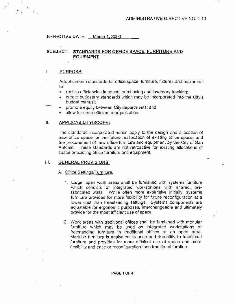

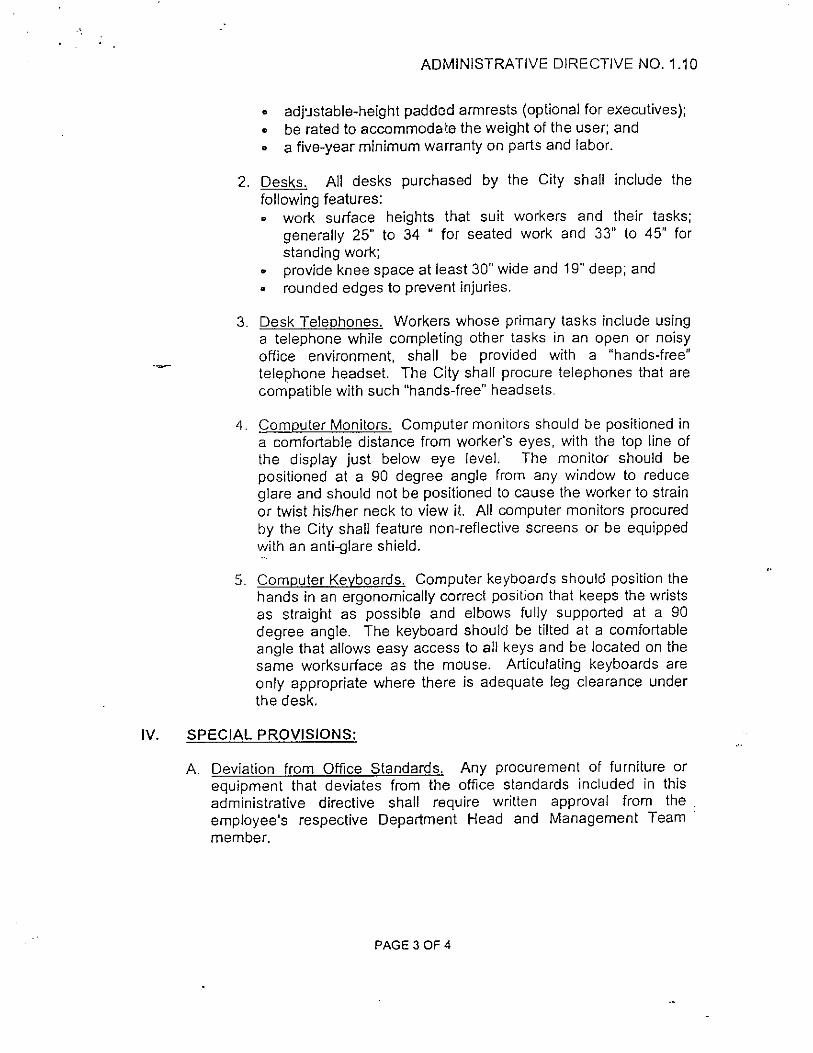


DAppendix


SYNOPSIS OF THE HEAD START CENTER DESIGN GUIDELINES
The purpose of this document is to condense the content of the “Head Start Center Design Guidelines” manual into a quick reference tool and to organize this data by typical physical space, rather than by topic. The first column is left blank with the word “Check” for you to indicate whether or not you have met the directive. The column represented by “M/R” indicates the priority of the item, “Mandatory” or Recommended”. The “Directive” column provides a description of the guideline to be met in the construction documents. “Item” indicates a general heading category to which the Directive applies. The “Ref” column points to the particular section in the referenced manual. The column with the “H/S/O” indicates the author of the directive. The “H” indicates that Head Start is the author of the directive. The “S” indicates that the State Department of Health is the author of the directive. The “O” indicates that some other source is the author of the directive. The architectural firm of Tompkins and Barron, Jackson, Mississippi developed this Head Start Design Guide Synopsis for the Region IV Head Start Quality Improvement Centers, Western Kentucky University. © TTAS, Inc copyrighted forms maybe reproduced for Head Start and Early Head Start use only

Site Design
H/S/OO Ref Item Directive M/R Check
H 5.4 Soils Testing Before design, soils certified to be free of contaminates M H 5.7 Parking Provide access for short term parking for busses, parents,
visitors R
H 5.7 Provide short term parking spaces for parents close to entrance
R
H 5.7 Provide long term parking for staff and others R H 6.2.2 Provide ADA parking at entrance R H 6.2.2 Short term parking should be visible from
director/reception R
H 6.2.1 Vehicle Access Drop off area direct child to entrance w/o crossing traffic R H 6.2.2 Walkway Hazard Walkways in front of vehicles, protect w/bumpers,
bollards, etc. R
H 10.11.2 ADA Requirements
Slope and rise: Parking, curbing, walkways, ramps, 1:16 to 1:20 is preferred with maximum 1:12
R
H 6.2.1 Transition Area Transition area (porch, canopy) at entrance R H 6.2.3 Service Access Provide two entrances to site. Public entry and service
entry R
H 6.2.3 Separate Service access from main entry R H 6.4.7 Site Furniture Provide benches in shaded area with view of play yard R H 6.4.7 Fall Zones Provide fall zones around play equipment. (See Handbook
for Public Playground Safety) M
Playground
H/S/O Ref Item Directive M/R Check
H 5.9.3 Purpose Play yard is an extension of classroom and easily accessed R H 6.3 Guidelines Design play yard by the Handbook for Public Ground Safety M H 5.3 Required Size Exterior – Play area, 75 SF play area per child. (Compute
area for half of the child population occupying play yard at one time)
M
H 5.3 Minimum Dim No dimension less than 8.1 feet (8’-2”) M H 5.3 Minimum Area Minimum area is 1,205 SF M H 6.4 Separate Play
Yards Separate Head Start and Early Head Start play yards. Visual contact is desired.
M
H 6.4.7 Site Furniture Provide benches in shaded area with view of play yard R H 6.3 Yard Activities Sand/water, art, dramatic play, large muscle plan R H 6.4.6 Dedicated wheeled toy pathways wide enough for passing
toys R
H 5.3 Sun Lighted Areas At least 50% of area is exposed to sunlight M

Playground H 5.3 Shaded Areas Porches, plantings, gazebos, umbrellas, etc. R H Minimum area, 6’ in any direction R H 6.4.7 Fall Zones Provide fall zones around play equipment. (See Handbook for
Public Playground Safety) M
H 6.7.5 Play Surfaces CPSC’s Handbook for Public Playground Safety M H 6.7.6 Resilient surfaces – pre-engineered wood chips, rubber
matting R
H 6.7.7 Hard Surfaces – Area for wheeled riding. Concrete, asphalt, etc.
R
H 6.7.7 Edges should flush with adjoining ground, paving, etc. R H 6.7.7 No gravel or loose stones allowed M H 6.7.7 Grass or turf is not recommended in Fall Zones R H 6.7.6 Artificial Turf, NOT recommended M H 6.7.6 Water should penetrate surfaces, and drain off beneath
surfaces R
H 6.7.1 Fencing 6’ high perimeter fencing when views into play yard are allowed
R
H 6.4 Interior fence: 3.3’ (3’-4”) high R H 6.7.1 Fence bottom, maximum 3” above grade R H 6.7.1 Pickets, posts, top capped with solid horizontal member R H 6.7.1 Spaces between pickets: 3.4 in x 9 in wide M H 6.7.1 No spaces between 0.3 in and 1 in M H 6.4 No ladder-like horizontal elements R H 6.7.1 Wood fences, smooth finish splinter free M H 6.7 GSA discourages chain link fences, other than vinyl coated R H 6.7.1 Gates Self closing and latching R H 6.4.6 Provide 2 access points. One from classroom, one from street R H 6.7.1 Street gate to be vehicle sized for service R H 5.9.3 Storage Outside storage of equipment, wheeled toys, etc. R H 6.4.8 Provide unique signage on storage so children can recognize R H 6.4.8 Maintain visibility into storage areas R H 6.4.8 Provide exterior locks, releasable from the inside R H 6.5.1 Sand/Water Play Children’s height play tables R H 6.5.1 Provide water source R H 6.5.1 Provide child-scaled drinking fountain R H 6.5.3 Berms Small scale berms provide cost effective challenges to
children R
H 6.5.3 Unapproved Play-ground Equipment
Metal slides, tunnel slides, seesaws, spring toys, swings R
H 6.5.3 ADA Accessible Play areas should be accessible to disabled children M H 6.6.3 Equipment Safety Safety guideline: Playing child should move, not equipment R H 6.7.2 Landscaping Use non-toxic plant materials R H 6.7.2 Use landscaping to define and separate different play areas R

Playground H 5.4 Hazards No drainage ditches, pools, drop-off, etc., in play yard M
Center Entrance
H/S/O Ref Item Directive M/R Check
H 6.7.3 Entrance Pathway Main entrance pathways, 6’ to 8’ wide R H 6.7.3 Paving Maximum slopes: 1:20 without handrail R H 6.7.3 Maximum Cross slopes: 1:50 R H 6.7.3 Handrails Use child-scaled handrail heights: 20 to 36 inches. Where
adult handrails are also required, provide two handrails at two heights.
R
H 6.7.3 Guardrails Provide guardrails for Infants and Toddlers at walk surfaces differing by 12” or more
R
H 6.7.3 Provide guardrails for Pre -Schoolers at walk surfaces differing by 20” or more
R
H 6.7.3 Top of guardrail 30” above walk surface R H 6.7.3 Guardrails shall not have openings from 3.4 to 9 inches R H 6.7.3 Guardrails shall not have openings form 0.3 to 1 inch R H 6.7.3 Guardrails on platforms more than 30”, no openings larger
than 3” and no horizontal footholds R
H 6.7.3 Platform Heights Maximum platform height for Infants is 18” R H 6.7.3 Maximum platform height for Toddlers is 36” R H 6.7.3 Maximum platform height for Pre-Schoolers is 4.5’ (4’-6”) R H 7.1.6 Entrance Doors Provide safety glass glazing in entrance doors R H 7.1.8 Entrance Mat Recessed walk-off mat at entrance doors R H 7.1.7 Bench Provide a bench near doorway for child/parent use R
Reception
H/S/O Ref Item Directive M/R Check
H 3.3 Location Visible monitoring and control of entry R H 5.6 Security Building entry should be secured and controlled R H 7.1.6 Vestibule A thermal lock vestibule is desired R H 7.1.6 Reception Desk Children should have full view of person at desk R H 7.1.6 An adult RR should be easily accessed from this area R H 7.1.9 Sign-in facility for parents R H 7.1.9 Parent/teacher mailboxes R H 3.3 Storage Lockable for personal items R H 3.3 Filing Cabinets R

Reception H 7.1.9 Furnishings Possibly sofa, chair, end table, coffee table. R H 7.1.6 Bench Locate a bench in this area for parent/child parting, etc. R H 7.1.9 Floors Carpet is recommended, or non-slip rugs R
Main Circulation
H/S/O Ref Item Directive M/R Check
H 7.1.10 Purpose Serves as a pathway and community space R H 7.1.10 Serve as a street with changing character, areas to pause, etc. R H 7.1.10 Serve as social area, display artwork, see into other
classrooms R
H 7.1.10 Create “landmarks” in hallways that children can orient to R H 7.1.10 Area Restriction Maximum 30% of Occupiable Area for circulation and
service. This includes circulation in classrooms. R
H 10.11.2 ADA Requirements
Passage width: Minimum clear width of aisles, corridors, 3’, with a passing space of 5’ every 200’.
R
H 7.1.10 Dead center fluorescent fixtures in a corridor is not recommended
R
H 7.1.10 Flooring Impervious floor finish R H 7.1.10 Use floor patterns to break up a long corridor R H 7.1.10 Color Use color to break up tunnel affect, but carefully R H 7.1.10 Walls Impervious surface up to wainscot height, paint above R H 7.1.10 Corners Eliminate square (90degree) outside corners when possible R H 7.1.10 Lighting Vary lighting with wall mounted fixtures, natural light R
Classroom – Infants (Early Head Start)
H/S/O Ref Item Directive M/R Check
H 4.1.6 Design Ratio Staff/children ratio sets classroom size. R H 5.3 Classroom Design Provide minimum 35sf usable space per child, exclusive of
bathrooms, halls, kitchen, staff room and storage. M
H 7.2.1 Design flexibility for small groups (4-5) and for whole class R H 7.2.1 Possible use of lofts and steps as play elements R H 7.4 Use varying ceiling heights, floor levels (steps, lofts,
platforms), and wall configurations when possible or practical.
R
H 7.7.4 Provide space for one crib per infant, spaced 36” apart R H 7.4 Walls Avoid sharp (90 degree) corners. Provide a ½” radius or R
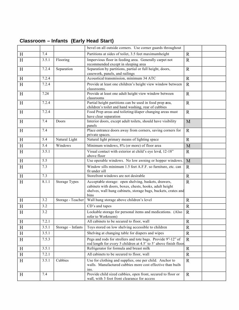
Classroom – Infants (Early Head Start) bevel on all outside corners. Use corner guards throughout
H 7.4 Partitions at sides of toilet, 3.5 feet maximum height R H 3.5.1 Flooring Impervious floor in feeding area. Generally carpet not
recommended except in sleeping area R
H 7.2.4 Separation Separation by partitions, partial or full height, doors, casework, panels, and railings
R
H 7.2.4 Acoustical transmission, minimum 34 ATC R H 7.2.4 Provide at least one children’s height view window between
classrooms. R
H 7.24 Provide at least one adult height view window between classrooms
R
H 7.2.4 Partial height partitions can be used in food prep area, children’s toilet and hand washing, rear of cubbies
R
H 7.2.4 Food Prep areas and toileting/diaper changing areas must have clear separation
R
H 7.4 Doors Interior doors, except adult toilets, should have visibility panels
M
H 7.4 Place entrance doors away from corners, saving corners for private spaces.
R
H 5.4 Natural Light Natural light primary means of lighting space R H 5.4 Windows Minimum windows, 8% (or more) of floor area M H 3.5.1 Visual contact with exterior at child’s eye level, 12-18”
above floor R
H 5.5 Use operable windows. No low awning or hopper windows. M H 7.3 Window sills minimum 1.5 feet A.F.F. so furniture, etc. can
fit under sill R
H 7.3 Storefront windows are not desirable R H 8.1.1 Storage Types Acceptable storage: open shelving, baskets, drawers,
cabinets with doors, boxes, chests, hooks, adult height shelves, wall hung cabinets, storage bags, buckets, crates and bins
R
H 3.2 Storage - Teacher Wall hung storage above children’s level R H 3.2 CD’s and tapes R H 3.2 Lockable storage for personal items and medications. (Also
refer to Workroom) R
H 7.2.1 All cabinets to be secured to floor, wall R H 3.5.1 Storage – Infants Toys stored on low shelving accessible to children R H 3.5.1 Shelving at changing table for diapers and wipes R H 7.5.3 Pegs and rods for strollers and tote bags. Provide 9”-12” of
rod length for every 5 children at 4.5’ to 5’ above finish floor. R
H 3.5.1 Refrigerator for formula and breast milk R H 7.2.1 All cabinets to be secured to floor, wall R H 3.5.1 Cubbies Use for clothing and supplies, one per child. Anchor to
walls. Manufactured cubbies more cost effective than built-ins.
R
H 7.4 Provide child sized cubbies, open front, secured to floor or wall, with 3 foot front clearance for access
R

Classroom – Infants (Early Head Start) H 7.5.3 Size, 12”w x 12”d x 18” high R H 7.5.2 Integral bench at 1.2 feet high is desirable R H 7.2.1 Cubbies might be arranged to form a cloakroom or entrance
with openings facing away from classroom R
H 3.5.1 Diaper Changing Must provide a visible connection with classroom R H 3.5.2 Infants & Young toddlers need changing table and toilet R H 7.7.3 Changing table to have impervious surface, easily cleaned R H 7.7.3 Wall surfaces adjacent to changing table to be impervious,
easily cleaned. R
H 7.7.3 Top surface 2.8’ above floor, minimum R H 7.7.3 Table: 2’ wide by 3.3’ long R H 7.7.3 Guide rails 3” above surface of changing table mat R H 7.7.3 Provide removable steps up to changing table, 5” risers. This
may be incorporated into bought changing table R
H 7.7.3 Provide space for air tight waste diaper container R H 7.7.3 Provide upper diaper storage cabinet within easy reach of the
diaper change table. Caregiver cannot leave baby to get supplies. Compartments are 9”w x 9”h x 12”deep
R
H 7.2.1 Diaper Sink Provide hand washing sink at diaper changing area R H 7.7.3 Locate within easy reach of changing table R H 7.4 Plumbing Group plumbing fixtures in one area. Separate food prep
from diaper changing areas R
H 7.7.3 Wrist blade faucet controls R H 7.7.3 Do NOT use gooseneck faucet at the diaper sink. (Splashes) R H 7.7.3 Provide paper towel dispenser R H 7.7.3 Provide soap dispenser R H 7.7.3 Provide rubber glove dispenser R H 7.2.1 Sleeping Area Provide area for cribs, one per infant, spaced 36” apart R H 7.7.4 Provide dimmable lighting in the sleeping area R H 7.2.1 Food Prep Area Provide food preparation area separate from Changing Area R H 7.7.6 Provide upper and lower cabinet storage. R H 7.7.6 Lower cabinets to have childproof latches R H 7.7.6 Adult scale counter, minimum 8’ long with splash R H 7.7.6 Counter height, 2.8’ (2’-10”) R H 7.7.6 Laminate plastic covered, with post formed edges and bends R H 7.7.6 Use non projecting drawer pulls R H 7.7.6 One cabinet should be lockable R H 7.7.6 Food Prep Sink Single lever faucet with spray hose R H 7.7.6 Provide garbage disposal in sink R H 7.7.6 Limit hot water temperature to 109.4 degrees R H 7.7.6 Food Prep
Refrigerator Provide minimum 8 cu. ft. refrigerator for food and medication storage
R

Classroom – Infants (Early Head Start) H 10.11.2 Sinks Sink top: Maximum height, 22” above floor, with minimum
19” knee clearance R
H 10.11.2 Sink faucets: Maximu m distance from counter top edge, 14” R H 4.1.3 Bulletin Board For parents and teachers R H 7.5.1 Sign-in counter (device) at classroom door, 2.7 feet above
finished floor with storage below. R
H 7.4 Display Area Provide wall area at children’s height for display of work R H 7.5.5 Provide continuous strips at 3.2’ to 4.5’ above finish floor to
attach children’s work for display R
H 7.4 Display device cannot use tacks R H 7.5.6 Mirrors Provide child shatterproof mirror, minimum 1.5’ high. No
sharp edges R
H 10.11.2 Full-length mirror, 18” above floor. All mirrors shatterproof. R H 3.5.1 Grab Bars Provide a minimum of 5’ in each classroom, mounted at 1.5’
above floor. Used to pull to standing position, practice walking
R
H 7.2.1 Adult Rest Room Adult rest room within 33.75 feet of entry R H 3.5.1 Drawings Locate with dimensions cribs, equipment, feeding
components M
H 3.2 Electrical Duplexes – Elevated outlets for TV, tapes, etc. Minimum 4.5’ above finish floor
R
H 3.5.1 Lighting - Dimmable lighting in crib area. (See “Natural Light” above)
R
H 7.7.4 Provide smoke detectors in classrooms R
Classroom – Toddlers (Early Head Start)
H/S/O Ref Item Directive M/R Check
H 4.1.6 Design Ratio Staff/children ratio sets classroom size. R H 5.3 Classroom Design Provide minimum 35sf usable space per child, exclusive of
bathrooms, halls, kitchen, staff room and storage. M
H 7.2.1 Design flexibility for small groups (4-5) and for whole class R H 7.2.1 Possible use of lofts and steps as play elements R H 7.4 Use varying ceiling heights, floor levels (steps, lofts,
platforms), and wall configurations when possible or practical.
R
H 7.4 Walls Avoid sharp (90 degree) corners. Provide a ½” radius or bevel on all outside corners. Use corner guards throughout
R
H 7.4 Partitions at sides of toilet, 3.5 feet maximum height R H 7.5.7 Flooring Impervious floor throughout R H 7.2.4 Separation Separation by partitions, partial or full height, doors,
casework, panels, and railings R
H 7.2.4 Acoustical transmission, minimum 34 ATC R

Classroom – Toddlers (Early Head Start) H 7.2.4 Provide at least one children’s height view window between
classrooms. R
H 7.24 Provide at least one adult height view window between classrooms
R
H 7.2.4 Partial height partitions can be used in food prep area, children’s toilet and hand washing, rear of cubbies
R
H 7.2.4 Food Prep areas and toileting/diaper changing areas must have clear separation
R
H 7.4 Doors Interior doors, except adult toilets, should have visibility panels
M
H 5.4 Natural Light Natural light primary means of lighting space R H 5.4 Windows Minimum windows, 8% (or more) of floor area M H 3.5.1 Visual contact with exterior at child’s eye level, 12-18”
above floor R
H 5.5 Use operable windows. No low awning or hopper windows. M H 7.3 Window sills minimum 1.5 feet A.F.F. so furniture, etc. can
fit under sill R
H 7.3 Storefront windows are not desirable R H 8.1.1 Storage Types Acceptable storage: open shelving, baskets, drawers,
cabinets with doors, boxes, chests, hooks, adult height shelves, wall hung cabinets, storage bags, buckets, crates and bins
R
H 3.2 Storage - Teacher Wall hung storage above children’s level R H 3.2 CD’s and tapes R H 3.2 Lockable storage for personal items and medications. (Also
refer to Workroom) R
H 7.2.1 All cabinets to be secured to floor, wall R H 7.7.8 Storage – YT &
OT Toys storage, low accessible shelving, 16”d x 30”h. Fixed or mobile.
R
H 3.5.1 Shelving at changing table for diapers and wipes R H 7.5.3 Pegs and rods for strollers and tote bags. Provide 9”-12” of
rod length for every 5 children at 4.5 ‘to 5’ above finish floor. R
H 3.5.1 Refrigerator for formula and breast milk R H 3.5.2 Mat or pad storage for naps R H 7.2.1 All cabinets to be secured to floor, wall R H 3.5.1 Provide hooks for satchel and backpacks near entry R H 3.5.1 Cubbies Use for clothing and supplies, one per child. Anchor to
walls. Manufactured cubbies more cost effective than built-ins.
R
H 7.4 Provide child sized cubbies, open front, secured to floor or wall, with 3 foot front clearance for access
R
H 7.5.3 Size, 12”w x 12”d x 3’ to 4’ high R H 7.5.2 Integral bench at 10” high is desirable R 7.5.4 Provide 2 hooks and a shelf for books, etc. R H 7.2.1 Cubbies might be arranged to form a cloakroom or entrance
with openings facing away from classroom R
H 3.5.1 Diaper Changing Must provide a visible connection with classroom R

Classroom – Toddlers (Early Head Start) H 3.5.2 Infants & Young toddlers need changing table and toilet R H 7.7.3 Changing table to have impervious surface, easily cleaned R H 7.7.3 Wall surfaces adjacent to changing table to be impervious,
easily cleaned. R
H 7.7.3 Top surface 2.8’ above floor, minimum R H 7.7.3 Table: 2’ wide by 3.3’ long R H 7.7.3 Guide rails 3” above surface of changing table mat R H 7.7.3 Provide removable steps up to changing table, 5” risers. This
may be incorporated into bought changing table R
H 7.7.3 Provide space for air tight waste diaper container R H 7.7.3 Provide upper diaper storage cabinet within easy reach of the
diaper change table. Caregiver cannot leave baby to get supplies. Compartments are 9”w x 9”h x 12”deep
R
H 7.2.1 Diaper Sink Provide hand washing sink at diaper changing area R H 7.7.3 Locate within easy reach of changing table R H 7.4 Plumbing Group plumbing fixtures in one area. Separate food prep
from diaper changing areas R
H 7.7.3 Wrist blade faucet controls R H 7.7.3 Do NOT use gooseneck faucet at the diaper sink. (Splashes) R H 7.7.3 Provide paper towel dispenser R H 7.7.3 Provide soap dispenser R H 7.7.3 Provide rubber glove dispenser R H 7.2.1 Sleeping Area Possible need area for some cribs, mats for resting R H 7.7.4 Provide dimmable lighting in the sleeping area R H 7.2.1 Food Prep Area Provide food preparation area separate from Changing Area R H 7.7.6 Provide upper and lower cabinet storage. R H 7.7.6 Lower cabinets to have childproof latches R H 7.7.6 Adult scale counter, minimum 8’ long with splash R H 7.7.6 Counter height, 2.8’ (2’-10”) R H 7.7.6 Laminate plastic covered, with post formed edges and bends R H 7.7.6 Use non projecting drawer pulls R H 7.7.6 One cabinet should be lockable R H 7.7.6 Food Prep Sink Single lever faucet with spray hose R H 7.7.6 Provide garbage disposal in sink R H 7.7.6 Limit hot water temperature to 109.4 degrees R H 7.7.6 Food Prep
Refrigerator Provide minimum 8 cu. ft. refrigerator for food and medication storage
R
H 4.1.3 Bulletin Board For parents and teachers R H 7.5.1 Sign-in counter (device) at classroom door, 2.7 feet above
finished floor with storage below. R
H 7.4 Display Area Provide wall area at children’s height for display of work R H 7.5.5 Provide continuous strips at 3.2’ to 4.5’ above finish floor to
attach children’s work for display R

Classroom – Toddlers (Early Head Start) H 7.4 Display device cannot use tacks R H 7.5.6 Mirrors Provide child shatterproof mirror, minimum 1.5’ high. No
sharp edges R
H 10.11.2 Full-length mirror, 18” above floor. All mirrors shatterproof. R H 7.7.7 Drinking Fount Provide room temperature drinking fountain R H 7.7.7 Mount drinking fountain at 1.8’ (1’-10”) above floor R H 10.8 Provide mouth guard, angled jet with spout height maximum
21” above floor R
H 3.5.1 Grab Bars Used to pull to standing position, practice walking R H 7.2.1 Adult Rest Room Adult rest room within 33.75 feet of entry R H 3.5.1 Drawings Locate with dimensions cribs, equipment, feeding
components M
H 7.4 Plumbing Group plumbing fixtures in one area. Separate food prep from diaper changing areas
R
H 7.2.1 Provide hand washing sink at diaper changing area R H 7.7.6 Food prep sink. Single lever faucet with spray hose R H 7.7.6 Provide garbage disposal in food prep sink R H 7.7.6 Limit food prep sink hot water temperature to 109.4 degrees R H 7.7.7 Provide room temperature drinking fount at 1.8’ (1’-10”)
A.F.F. R
H 3.2 Electrical Duplexes – Elevated outlets for TV, tapes, etc. Minimum 4.5’ above finish floor
R
H 3.5.1 Lighting - Dimmable lighting in crib area. (See “Natural Light” above)
R
Classroom – Pre-School (Head Start)
H/S/O Ref Item Directive M/R Check
H 4.1.6 Design Ratio Staff/children ratio sets classroom size. R H 5.3 Classroom
Design Provide minimum 35sf usable space per child, exclusive of bathrooms, halls, kitchen, staff room and storage.
M
H 7.2.1 Design flexibility for small groups (4-5) and for whole class R H 7.2.1 Possible use of lofts and steps as play elements R H 7.2.1 Locate with easy access to outside play yards R H 7.4 Use varying ceiling heights, floor levels (steps, lofts,
platforms), and wall configurations when possible or practical.
R
H 7.4 Walls Avoid sharp (90 degree) corners. Provide a ½” radius or bevel on all outside corners. Use corner guards throughout
R
H 7.4 Partitions at sides of toilet, 3.5 feet maximum height R H 7.2.4 Separation Separation by partitions, partial or full height, doors,
casework, panels, and railings R
H 7.2.4 Acoustical transmission, minimum 34 ATC R H 7.2.4 Provide at least one children’s height view window between R
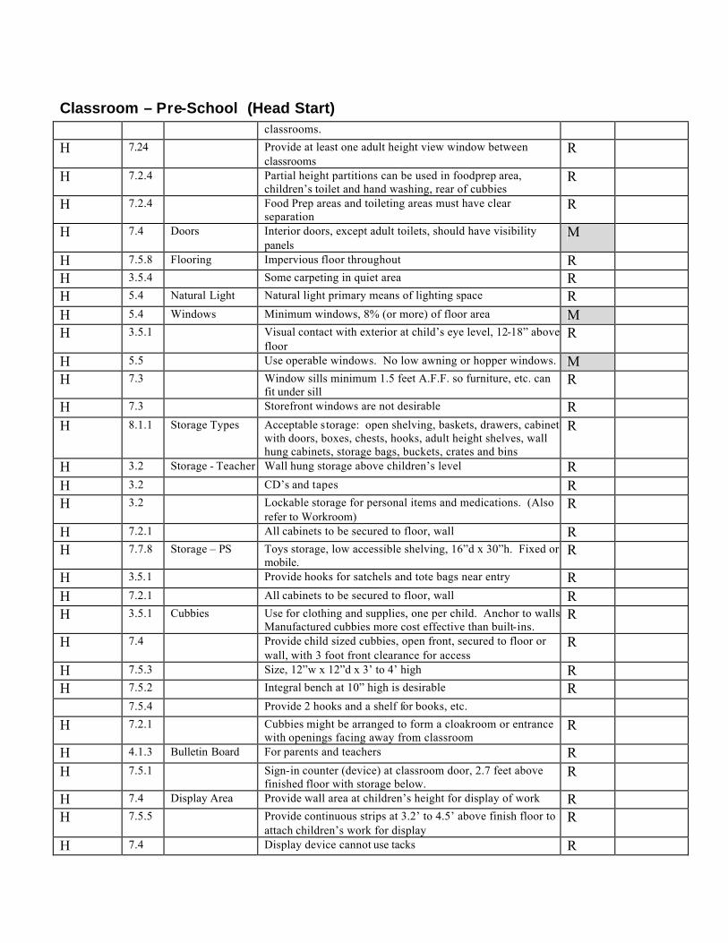
Classroom – Pre-School (Head Start) classrooms.
H 7.24 Provide at least one adult height view window between classrooms
R
H 7.2.4 Partial height partitions can be used in food prep area, children’s toilet and hand washing, rear of cubbies
R
H 7.2.4 Food Prep areas and toileting areas must have clear separation
R
H 7.4 Doors Interior doors, except adult toilets, should have visibility panels
M
H 7.5.8 Flooring Impervious floor throughout R H 3.5.4 Some carpeting in quiet area R H 5.4 Natural Light Natural light primary means of lighting space R H 5.4 Windows Minimum windows, 8% (or more) of floor area M H 3.5.1 Visual contact with exterior at child’s eye level, 12-18” above
floor R
H 5.5 Use operable windows. No low awning or hopper windows. M H 7.3 Window sills minimum 1.5 feet A.F.F. so furniture, etc. can
fit under sill R
H 7.3 Storefront windows are not desirable R H 8.1.1 Storage Types Acceptable storage: open shelving, baskets, drawers, cabinets
with doors, boxes, chests, hooks, adult height shelves, wall hung cabinets, storage bags, buckets, crates and bins
R
H 3.2 Storage - Teacher Wall hung storage above children’s level R H 3.2 CD’s and tapes R H 3.2 Lockable storage for personal items and medications. (Also
refer to Workroom) R
H 7.2.1 All cabinets to be secured to floor, wall R H 7.7.8 Storage – PS Toys storage, low accessible shelving, 16”d x 30”h. Fixed or
mobile. R
H 3.5.1 Provide hooks for satchels and tote bags near entry R H 7.2.1 All cabinets to be secured to floor, wall R H 3.5.1 Cubbies Use for clothing and supplies, one per child. Anchor to walls.
Manufactured cubbies more cost effective than built-ins. R
H 7.4 Provide child sized cubbies, open front, secured to floor or wall, with 3 foot front clearance for access
R
H 7.5.3 Size, 12”w x 12”d x 3’ to 4’ high R H 7.5.2 Integral bench at 10” high is desirable R 7.5.4 Provide 2 hooks and a shelf for books, etc. H 7.2.1 Cubbies might be arranged to form a cloakroom or entrance
with openings facing away from classroom R
H 4.1.3 Bulletin Board For parents and teachers R H 7.5.1 Sign-in counter (device) at classroom door, 2.7 feet above
finished floor with storage below. R
H 7.4 Display Area Provide wall area at children’s height for display of work R H 7.5.5 Provide continuous strips at 3.2’ to 4.5’ above finish floor to
attach children’s work for display R
H 7.4 Display device cannot use tacks R

Classroom – Pre-School (Head Start) H 7.5.6 Mirrors Provide child shatterproof mirror, minimum 1.5’ high. No
sharp edges R
H 10.11.2 Full-length mirror, 18” above floor. All mirrors shatterproof. R H 7.7.7 Drinking Fount Provide room temperature drinking fountain R H 7.7.7 Mount drinking fountain at 1.8’ (1’-10”) above floor R H 7.7.1 Children’s Sink Children’s sink cabinet, 22” high, 16” to 22” deep, 3’ to 4’
countertop length adjacent to sink. (See also Plumbing) R
H 7.4 Plumbing Group plumbing fixtures in one area. Separate food prep from diaper changing areas
R
H 7.7.1 Children’s sink, stainless steel, goose-neck faucet, wrist handles, mounted 22” above floor. Counter, 16” to 22” deep.
R
H 7.7.7 Provide room temperature drinking fountain 1.8’ (1’-10”) A.F.F.
R
H 7.7.2 Provide water play plumbing connection R H 3.2 Electrical Duplexes – Elevated outlets for TV, tapes, etc. Minimum 4.5’
above finish floor R
H 3.5.1 Lighting - Dimmable lighting. (See “Natural Light” above) R H 7.3 General pendent lighting/ceiling fans, no lower than 7.5 feet R H 7.3 Pendent task lighting, no lower than 5.5 feet R
Children’s Classroom Toilet
H/S/O Ref Item Directive M/R Check
H 7.3 Location Locate in classroom area, separated from food preparation R H 7.7.2 Toilets should be partially screened from main classroom R H 7.7.2 Two classrooms can share one toilet area R H 7.7.2 Toddlers: Use child scaled fixtures. WC seats, 11” high. R H 7.7.2 Preschoolers: Use adult WC R H 7.7.2 Flooring Impervious flooring. Ceramic tile floor, base, wainscot to 3’
high, painted wall above. R
H 7.1.15 Walls Impervious wainscot, paint above R H 7.7.2 Water Closets Minimum 1 toilet, 2 child height hand washing sinks in each
classroom M
H (Ap A) Toilets: Provide at a ratio of roughly 1:10 for toddlers and preschoolers.
R
H (Ap A) Maximum toilet height: 11” R H 10.11.2 Water closet flushing controls: Front mounted, 20 to 30
above floor. R
H 7.7.2 Lavs/Hand Sinks One lavatory, one drinking fountain per every 10 children M H 7.7.2 Hand washing sinks can be located within toilet area, but best
located in classroom on wall adjacent to toilet area R
H 7.7.2 Mount sink 22” above floor. R H (Ap A) Maximum children hand sink height: 22” R

Children’s Classroom Toilet H 7.7.2 Counter top depth, 16” to 22” R H 7.7.2 Hot water temperature, maximum 109.4 degrees R H 10.11.2 Accessories Mirrors: Mounted over sink, 29.5” bottom edge to floor. All
mirrors shatterproof. R
H 7.7.2 Provide paper towel dispenser at each sink. Metered roll dispensers are preferred. No serrated tear edges allowed
R
H 7.7.2 Provide soap dispensers at each sink R H 10.11.2 Toilet paper dispensers: Mount 14” above floor R H 7.7.2 Toddlers Minimum 2 adult sinks, (1) diapering and (1) food
preparation M
H 7.7.2 Preschoolers Minimum 1 adult sink, 1 or 2 hand washing sinks for every 10-20 children.
M
H 7.1.15 ADA Meet all ADA requirements R H 7.7.2 Doors Doors should not lock in toilets R H 7.7.2 Doors or gates should be half height R H 7.7.2 Door hardware should have hinge protection to prevent
hand/finger crushing R
H 7.7.2 Floor Drain Provide floor drain in toilet rooms R H 7.7.2 Exhaust
Ventilation Provide exhaust ventilation in toilet areas R
H (Ap A) Plumbing Maximum toilet height: 11” R H 10.11.2 Water closet flushing controls: Front mounted, 20 to 30
above floor. R
Office – Director
H/S/O Ref Item Directive M/R Check
H 4.1.5 Purpose Administrative space for center director R H 7.1.12 Meet with parents, staff members, children R H 4.1.5 Location Facilitate frequent contact with children, parents, staff R H 7.1.12 Locate near reception, accessible to visitors R H 7.1.12 Desirable to have views of main entry receptions and
classrooms R
H 7.1.12 Floors Carpet R H 7.1.12 Walls Washable R H 7.1.12 Acoustical Acoustical separation of at least 45 STC from children’s area R H 7.1.12 Furnishing Desk, hair, two side chairs, filing cabinet, coat rack, book
shelving, lockable storage cabinet or closet for personal items & first aid
R
H 3.3 Equipment Telephone, security video monitors, computer, and printer. R H 3.3 Copier and fax machine if not located elsewhere R

Laundry
H/S/O Ref Item Directive M/R Check
H 7.7.15 Access Only accessible to adults with lockable door that can be opened from the inside.
R
H 7.7.15 Location Locate near Infants and Toddler classrooms R H 7.7.15 Locate near or on an exterior wall to facilitate venting R H 7.7.15 Equipment Heavy duty residential type washer and dryer R H 7.7.15 Folding counter R H 7.7.15 Lockable wall cabinets for chemicals, etc. R H 7.7.15 Deep Sink Deep sink desirable R H 7.7.15 Floor Drain Floor drain desirable R
Janitorial
H/S/O Ref Item Directive M/R Check
H 7.7.16 Equipment Mop sink with plumbing connections R H 7.7.16 Storage Provide storage for pails, mops, vacuums, etc. R H 7.7.16 Provide locked closet or space for cleaning chemicals.
Locked door should be capable of opening from the inside. R
H 7.7.16 Chemical cabinets should be lockable R H 7.7.16 Ventilation Exhaust ventilation is recommended R
Kitchen
H/S/O Ref Item Directive M/R Check
H 3.4 Food Service Efficient arrangement for transit of food to classrooms R H 7.7.14 Flooring Impervious flooring R H 7.7.14 Ceiling Washable (cleanable) ceiling system R H 7.7.14 Storage Closed storage for dry food, equipment, and supplies on metal
shelving R
H 7.7.14 Recycling bin R H 7.7.14 Equipment Stainless 3-compartment sink w/gooseneck faucets R H 7.7.14 Garbage disposal R H 7.7.14 Commercial refrigerator, with storage at 39.2 degrees and
freezer storage at or below -0.4degrees. (Some agencies require 2)
R

Kitchen H 7.7.14 Heavy duty commercial dishwasher R H 7.7.14 Microwave oven R H 7.7.14 Convection oven and range R H 7.7.14 Separate hand washing sink R H 7.7.14 Stainless steel counters, minimum 24” deep R H 7.7.14 Serving Carts Provide minimum of 2 food serving carts R H 7.7.14 Other Floor drain R H 7.7.14 Dietitian’s corner with telephone R
Conference/Parent Room
H/S/O Ref Item Directive M/R Check
H 4.1.3 Purpose Private consultation between parents and teachers R H 4.1.4 Training sessions and staff meetings R H 5.9.4 Rest Room
Access Parents should have easy access to adult (staff) rest room R
H 7.1.13 Furnishing Conference table, chairs R H 7.1.13 Shelving for books R H 7.1.13 Bulletin board R H 7.1.13 Lighting Dimmable lighting for videos R
Lounge
H/S/O Ref Item Directive M/R Check
H 4.1.3 Purpose Quite, private area for staff R H 7.1.14 Staff eats, relaxes, plans curriculum R H 7.1.14 Location Convenient to staff, close to adult toilet R H 7.1.14 Flooring Impervious flooring R H 4.1.3 Storage Lockable storage for staff (Also refer to Workroom) R H 7.1.14 Cabinet Hardware All base cabs to have childproof hardware R H 7.1.14 Equipment Provide microwave, sink, refrigerator, cabinets R H 7.1.14 Furnishing Possible sofa, tables, chairs R
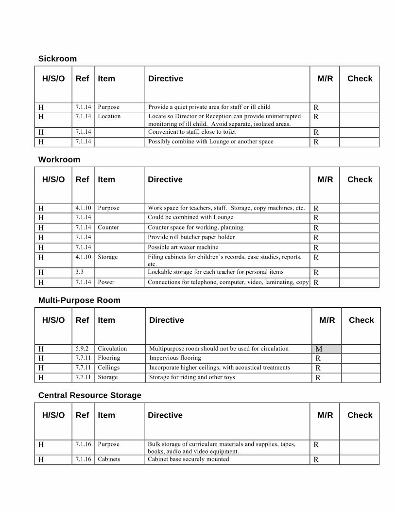
Sickroom
H/S/O Ref Item Directive M/R Check
H 7.1.14 Purpose Provide a quiet private area for staff or ill child R H 7.1.14 Location Locate so Director or Reception can provide uninterrupted
monitoring of ill child. Avoid separate, isolated areas. R
H 7.1.14 Convenient to staff, close to toilet R H 7.1.14 Possibly combine with Lounge or another space R
Workroom
H/S/O Ref Item Directive M/R Check
H 4.1.10 Purpose Work space for teachers, staff. Storage, copy machines, etc. R H 7.1.14 Could be combined with Lounge R H 7.1.14 Counter Counter space for working, planning R H 7.1.14 Provide roll butcher paper holder R H 7.1.14 Possible art waxer machine R H 4.1.10 Storage Filing cabinets for children’s records, case studies, reports,
etc. R
H 3.3 Lockable storage for each teacher for personal items R H 7.1.14 Power Connections for telephone, computer, video, laminating, copy R
Multi-Purpose Room
H/S/O Ref Item Directive M/R Check
H 5.9.2 Circulation Multipurpose room should not be used for circulation M H 7.7.11 Flooring Impervious flooring R H 7.7.11 Ceilings Incorporate higher ceilings, with acoustical treatments R H 7.7.11 Storage Storage for riding and other toys R
Central Resource Storage
H/S/O Ref Item Directive M/R Check
H 7.1.16 Purpose Bulk storage of curriculum materials and supplies, tapes, books, audio and video equipment.
R
H 7.1.16 Cabinets Cabinet base securely mounted R

Central Resource Storage H 7.1.16 Minimum height, 4.5 feet above finish floor R H 7.1.16 Open shelving, lockable storage, closed-door storage, filing
cabinets. R

EAppendix


Elementary School Design Guide Standards Updated 02/10/12 Chapter 2: Site Development
2-2.0
OUTDOOR PLAYGROUND AND FIELD AREA STANDARDS Playground designs and equipment shall adhere to the current Handbook for Public Playground Safety, U. S. Consumer Product Safety Commission, Publication No. 325, the Consumer Product Safety Improvement Act, (CPSIA 2008), ASTM's F1292-04, F1951-09B and F2075- 04e1 and the Texas Accessibility Standards. 1. FUNCTION OF AREA:
A. FIELD AREA:
1. Two (2) softball/kickball diamonds with 8’ height chain link backstops. Approximate size 175-200 foot radius from home plate.
2. One (1) multi purpose football/soccer field. Approximate size 100 yards by 50 yards. 3. All fields shall be designed with a maximum 2% slope.
B. PLAYGROUND AREA:
1. FIRST THROUGH FIFTH GRADE PLAYGROUND AREA: a. Three (3) swing sets – Each with six seats (3 bays) with a 10' top rail. One (1)
rubber wear mat 3’ x 6’ shall be installed under each swing seat for a total of eighteen (18). Refer to Illustration 2-2 Exhibit A.
b. One (1) modular playscape. One rubber wear mat 4’ x 4’ shall be installed under slides for a total of two (2). Refer to Illustration 2-2 Exhibits A and B and I for layout information.
c. One (1) obstacle course with five (5) stations. Refer to Illustration 2-2 Exhibit B & B-2 for layout information.
d. One (1) freestanding Tic-Tac-Toe Play Panel. Refer to Illustration 2-2 Exhibit I for layout information.
e. Surfacing under playground equipment shall be Engineered Wood Fiber material. Surfacing shall extend beyond the equipment per the drawings included. This area is called the fall zone and it shall be bordered by an earth berm in most areas. Exceptions to the berm would be sidewalks, fences, or buildings that can provide the function of a border. No curbing, edging or manufactured plastic edging is used. Reference Illustration 2-2 Exhibit C, for Berm detail and Illustration 2-2 Exhibit D for sidewalk detail. *
f. At least one concrete pathway (sidewalk) accessible route leading to the play area. Provide wheelchair accessibility from the sidewalk into the Engineered Wood Fiber area. Refer to ramp detail Illustration 2-2 Exhibit H-1 and H-2 as applicable.
g. A drainage system will be installed, per the drawings. Reference Illustration 2-2 Exhibit F or Illustration 2-2 Exhibit G for typical details as appropriate.
h. No tetherballs. 2. KINDER PLAYGROUND AREA:
a. One (1) modular playscape. One rubber wear mat, (4’ x 4’) shall be installed under the slides for a total of two (2). Reference Illustration 2-2 Exhibits A and E.
b. One (1) Geodesic dome climber. Reference Illustration 2-2 Exhibit E. c. One (1) swing set – features four seats (2 bays) 8' top rail. One rubber mat shall
be installed under each swing seat for a total of four, (4). Reference illustration 2-2, Exhibits A and E.
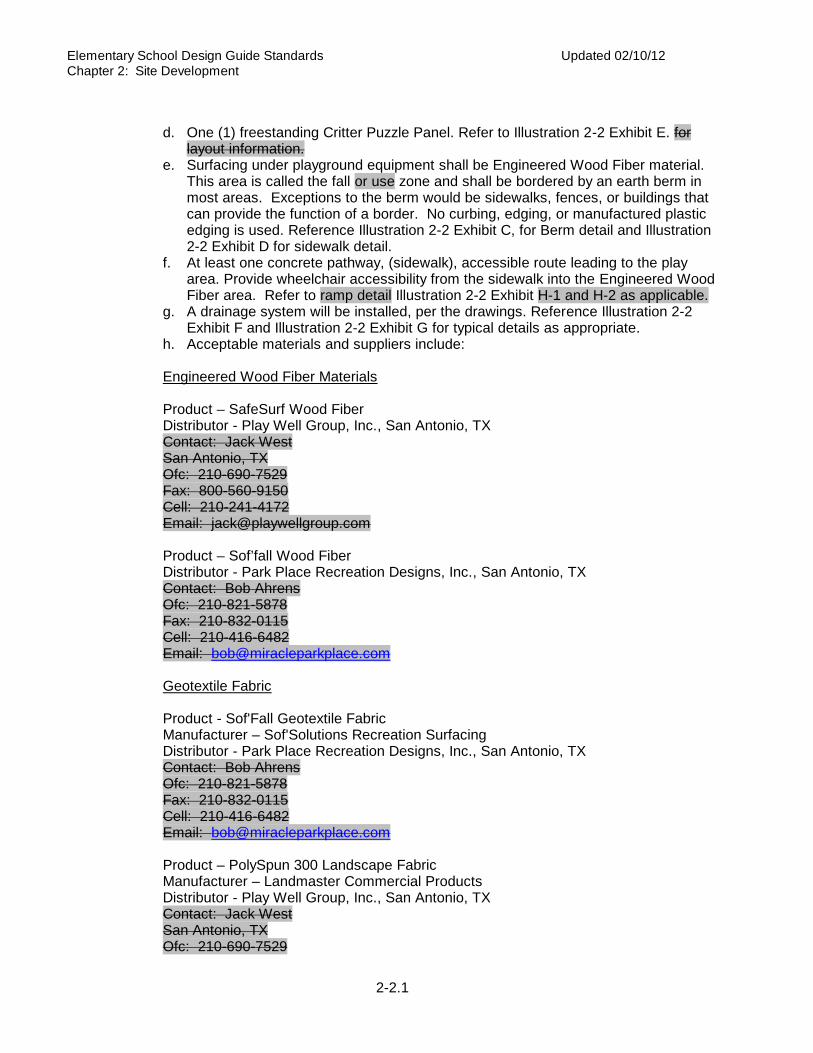
Elementary School Design Guide Standards Updated 02/10/12 Chapter 2: Site Development
2-2.1
d. One (1) freestanding Critter Puzzle Panel. Refer to Illustration 2-2 Exhibit E. for layout information.
e. Surfacing under playground equipment shall be Engineered Wood Fiber material. This area is called the fall or use zone and shall be bordered by an earth berm in most areas. Exceptions to the berm would be sidewalks, fences, or buildings that can provide the function of a border. No curbing, edging, or manufactured plastic edging is used. Reference Illustration 2-2 Exhibit C, for Berm detail and Illustration 2-2 Exhibit D for sidewalk detail.
f. At least one concrete pathway, (sidewalk), accessible route leading to the play area. Provide wheelchair accessibility from the sidewalk into the Engineered Wood Fiber area. Refer to ramp detail Illustration 2-2 Exhibit H-1 and H-2 as applicable.
g. A drainage system will be installed, per the drawings. Reference Illustration 2-2 Exhibit F and Illustration 2-2 Exhibit G for typical details as appropriate.
h. Acceptable materials and suppliers include: Engineered Wood Fiber Materials Product – SafeSurf Wood Fiber Distributor - Play Well Group, Inc., San Antonio, TX Contact: Jack West San Antonio, TX Ofc: 210-690-7529 Fax: 800-560-9150 Cell: 210-241-4172 Email: [email protected] Product – Sof’fall Wood Fiber Distributor - Park Place Recreation Designs, Inc., San Antonio, TX Contact: Bob Ahrens Ofc: 210-821-5878 Fax: 210-832-0115 Cell: 210-416-6482 Email: [email protected] Geotextile Fabric Product - Sof'Fall Geotextile Fabric Manufacturer – Sof'Solutions Recreation Surfacing Distributor - Park Place Recreation Designs, Inc., San Antonio, TX Contact: Bob Ahrens Ofc: 210-821-5878 Fax: 210-832-0115 Cell: 210-416-6482 Email: [email protected] Product – PolySpun 300 Landscape Fabric Manufacturer – Landmaster Commercial Products Distributor - Play Well Group, Inc., San Antonio, TX Contact: Jack West San Antonio, TX Ofc: 210-690-7529
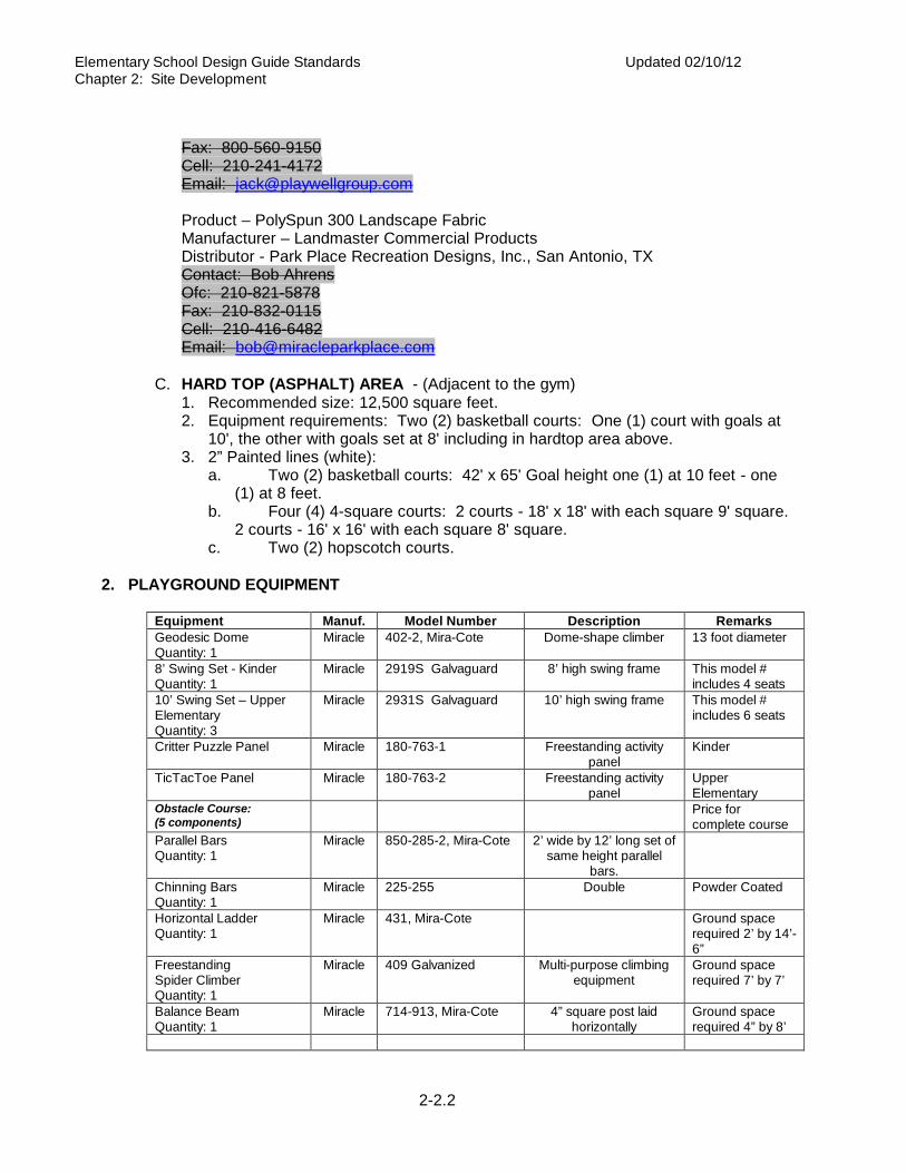
Elementary School Design Guide Standards Updated 02/10/12 Chapter 2: Site Development
2-2.2
Fax: 800-560-9150 Cell: 210-241-4172 Email: [email protected] Product – PolySpun 300 Landscape Fabric Manufacturer – Landmaster Commercial Products Distributor - Park Place Recreation Designs, Inc., San Antonio, TX Contact: Bob Ahrens Ofc: 210-821-5878 Fax: 210-832-0115 Cell: 210-416-6482 Email: [email protected]
C. HARD TOP (ASPHALT) AREA - (Adjacent to the gym)
1. Recommended size: 12,500 square feet. 2. Equipment requirements: Two (2) basketball courts: One (1) court with goals at
10', the other with goals set at 8' including in hardtop area above. 3. 2” Painted lines (white):
a. Two (2) basketball courts: 42' x 65' Goal height one (1) at 10 feet - one (1) at 8 feet.
b. Four (4) 4-square courts: 2 courts - 18' x 18' with each square 9' square. 2 courts - 16' x 16' with each square 8' square.
c. Two (2) hopscotch courts. 2. PLAYGROUND EQUIPMENT
Equipment Manuf. Model Number Description Remarks Geodesic Dome Quantity: 1
Miracle 402-2, Mira-Cote Dome-shape climber 13 foot diameter
8’ Swing Set - Kinder Quantity: 1
Miracle 2919S Galvaguard 8’ high swing frame This model # includes 4 seats
10’ Swing Set – Upper Elementary Quantity: 3
Miracle 2931S Galvaguard 10’ high swing frame This model # includes 6 seats
Critter Puzzle Panel Miracle 180-763-1 Freestanding activity panel
Kinder
TicTacToe Panel Miracle 180-763-2 Freestanding activity panel
Upper Elementary
Obstacle Course: (5 components)
Price for complete course
Parallel Bars Quantity: 1
Miracle 850-285-2, Mira-Cote 2’ wide by 12’ long set of same height parallel
bars.
Chinning Bars Quantity: 1
Miracle 225-255 Double Powder Coated
Horizontal Ladder Quantity: 1
Miracle 431, Mira-Cote Ground space required 2’ by 14’-6”
Freestanding Spider Climber Quantity: 1
Miracle 409 Galvanized Multi-purpose climbing equipment
Ground space required 7’ by 7’
Balance Beam Quantity: 1
Miracle 714-913, Mira-Cote 4” square post laid horizontally
Ground space required 4” by 8’

Elementary School Design Guide Standards Updated 02/10/12 Chapter 2: Site Development
2-2.3
Equipment Manuf. Model Number Description Remarks Kinder: Tot’s Choice Playscape:
Tots Choice -1267 Price for complete playscape
Transfer Point w/single step (3’ Deck) Quantity: 1
Miracle 718-965359 ADA accessible
Curved Loop Climber Quantity: 1
Miracle 718-968 The loop climber is an accessory for the 3’ deck
Spider Climber Quantity: 1
Miracle 718-908
ADA Stair between decks, 1’ rise Quantity: 1
Miracle 718-810059
Decks Quantity: 1
Miracle 718-501 (3) Openings Tri-deck
Decks Quantity: 1
Miracle 718-502 (4) Openings Square Deck
Square Roof Quantity: 1
Miracle 718-861-4 Shingle pattern 60” square by 32” high at center
Mogul Slide Quantity: 1
Miracle 718-726-4 18” wide sliding surface To be used w/4’ deck
Groove Slide Quantity: 1
Miracle 718-727-4 18” wide sliding surface To be used w/4’ deck
Steel Posts Quantity: 7
Miracle 718-552 718-573
Steel Posts 3 ½" O.D.
Upper Elementary Playscape:
Kids choice -1261
Price for complete playscape
Decks Quantity: 3
Miracle 714-5029 4’ Square Deck
Steel Posts Quantity: 15
Miracle 714-552, 714-572, 714-573
Steel Posts 5” O.D.
Square Roof Quantity: 2
Miracle 714-861-4 Shingle pattern 60” square by 32” high at center
Typhoon Spiral Slide to 5’ deck Quantity: 1
Miracle 714-74959 30” wide slide w/15” sidewalls
Deck Enclosure Quantity: 2
Miracle 714-813-5
Vertical Ladder Quantity: 2
Miracle 714-815-3
Side-by-side Slide Quantity: 1
Miracle 714-700 To be used w/3’ deck
“S” Double Rail – Left Quantity: 1
Miracle 714-952-5 Overhead climber
Double Rail Climber Quantity: 1
Miracle 714-899 To be used w/5’ deck
Spider Climber Quantity: 1
Miracle 714-908 Pole with “U” shape rungs
Spider Ladder Quantity: 1
Miracle 714-964-5
Stairs Quantity: 1
Miracle 714-959 ATA Stair 2’ rise (spokes)
Transfer Point w/single Miracle 714-965 ADA accessible

Elementary School Design Guide Standards Updated 02/10/12 Chapter 2: Site Development
2-2.4
Equipment Manuf. Model Number Description Remarks step (3’ Deck) Quantity: 1 Curved Loop Climber Quantity: 1
Miracle 714-968 To be used w/ 3’ deck
End Ladders for overhead climbers Quantity: 2
Miracle 714-815-5 To be used with overhead climbers to access 2-8’ high 2-10’ high
Basketball Goals Quantity. 4
Miracle 360-753 Fixed Goal Package
3. SPECIAL REQUIREMENTS: See Facilities Systems Design Guide. 4. ILLUSTRATIONS: 2-2 Exhibit A, B, B-2, C, D, E, F, G, H and I.


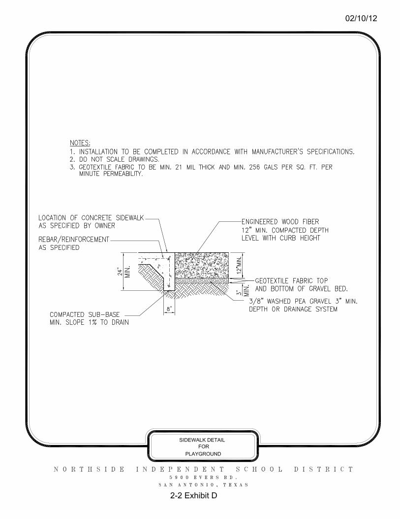


07-19-2012
NISD Playground Dimension Checklist Kinder Playground Wood fiber depth – over all - 12”minimum, from top of wood fiber surface to the geo-textile fabric above the drainage pea-gravel. Wood fiber depth – under swing seats and at end of slides – 6” minimum, from top of wood fiber surface to the middle of the wear mat and 6” minimum from the middle of the wear mat to the geo-textile fabric above the drainage pea-gravel. Swing set - top rail height – 8’ 0” from rail to the top of the wood fiber surface. Swing set fall zone – 16’ 0” minimum extending each swing direction from the center of the top rail. Fall zone shall be a minimum of 6’0” from each end of the swing set frame. If two swing sets are positioned end to end, this fall zone is allowed to overlap so that it is a minimum of 6’0” from swing set frame to the adjacent swing set frame. Swing set – seat height – 16” to 20” from center of swing seat to the top of the wood fiber surface, for regular swings only. *All swing seat measurements should be taken after the seat chains are fully extended from the top rail and then pushing the swing seat down towards the ground as far as possible. The distance is then measured from the center of the seat to the top of the wood fiber surfacing. Playscape - Slide exit height – No more than 11” from slide exit surface to the top of the wood fiber surface. Transfer point height - 11” to 18” from transfer point to the top of the wood fiber surface. Play Panels – interactive, freestanding Critter Puzzle Panel – 4” to 6” from bottom of panel to the top of the wood fiber surface. A freestanding panel does not require a fall zone, but must not encroach within the fall zone of another piece of play equipment.

07-19-2012
NISD Playground Dimension Checklist Upper Level Playground Wood fiber depth – over all - 12”minimum, from top of wood fiber surface to the geo-textile fabric above the drainage pea-gravel. Wood fiber depth – under swing seats and at end of slides – 6” minimum, from top of wood fiber surface to the middle of the wear mat and 6” minimum from middle of wear mat to the geo-textile fabric above the drainage pea-gravel. Swing set - top rail height – 10’ 0” from rail to the top of the wood fiber surface. Swing set fall zone – 20’ 0” minimum extending each swing direction from the center of the top rail. Fall zone shall be a minimum of 6’0” from each end of the swing set frame. If two swing sets are positioned end to end, this fall zone is allowed to overlap so that it is a minimum of 6’0” from swing set frame to the adjacent swing set frame. Swing set – seat height – 20” to 24” from center of swing seat to the top of the wood fiber surface, for regular swings only. *All swing seat measurements should be taken after the seat chains are fully extended from the top rail and then pushing the swing seat down towards the ground as far as possible. The distance is then measured from the center of the seat to the top of the wood fiber surfacing. Playscape - Slide exit height - 7” to 15” from slide to the top of the wood fiber surface. A fall zone of a minimum of 6’0” must surround the Playscape’s physical footprint. This fall zone increases to a minimum of 8’0” directly outbound from the spiral slide. Overhead climbers must not exceed 84” from the center of the grasping device of the climber to the surface of the wood fiber surfacing. Transfer point height - 11” to 18” from transfer point to the top of the wood fiber surface. Horizontal Ladder - Shall have a minimum 6’0” fall zone surrounding the equipment. When positioning freestanding climbers, the fall zones of two climbers can overlap to a minimum of 9’ from climber to adjacent climber. Overhead climbers must not exceed 84” from the center of the grasping device of the climber to the surface of the wood fiber surfacing.

07-19-2012
Chinning Bars - Shall have a minimum 6’0” fall zone surrounding the equipment. When positioning freestanding climbers, the fall zones of two climbers can overlap to a minimum of 9’ from climber to adjacent climber. Balance Beam - Shall have a minimum 6’0” fall zone surrounding the equipment. When positioning freestanding climbers, the fall zones of two climbers can overlap to a minimum of 9’ from climber to adjacent climber. Parallel Bars - Shall have a minimum 6’0” fall zone surrounding the equipment. When positioning freestanding climbers, the fall zones of two climbers can overlap to a minimum of 9’ from climber to adjacent climber. Spider Climber - Shall have a minimum 6’0” fall zone surrounding the equipment. When positioning freestanding climbers, the fall zones of two climbers can overlap to a minimum of 9’ from climber to adjacent climber. Play Panels – interactive, freestanding Tic Tac Toe Panel – 4” to 6” from bottom of panel to the top of the wood fiber surface. A freestanding panel does not require a fall zone, but must not encroach within the fall zone of another piece of play equipment.


FAppendix


LEED
200
9 fo
r N
ew C
onst
ruct
ion
and
Maj
or R
enov
atio
nsPr
ojec
t N
ame
Pro
ject
Che
cklis
tD
ate
Poss
ible
Poi
nts:
26
Y?
NY
?N
YPr
ereq
1
Cre
dit
41
to 2
Cre
dit
1 1
Cre
dit
51
to 2
Cre
dit
2 5
Cre
dit
6Ra
pidl
y Re
new
able
Mat
eria
ls1
Cre
dit
3Br
ownf
ield
Red
evel
opm
ent
1C
redi
t 7
1C
redi
t 4.
16
Cre
dit
4.2
1Po
ssib
le P
oint
s:
15C
redi
t 4.
3Al
tern
ativ
e Tr
ansp
orta
tion
—Lo
w-E
mit
ting
and
Fue
l-Ef
fici
ent
Vehi
cles
3C
redi
t 4.
42
YPr
ereq
1
Cre
dit
5.1
Site
Dev
elop
men
t—Pr
otec
t or
Res
tore
Hab
itat
1Y
Prer
eq 2
Cre
dit
5.2
Site
Dev
elop
men
t—M
axim
ize
Ope
n Sp
ace
1C
redi
t 1
1C
redi
t 6.
1St
orm
wat
er D
esig
n—Q
uant
ity
Cont
rol
1C
redi
t 2
1C
redi
t 6.
2St
orm
wat
er D
esig
n—Q
ualit
y Co
ntro
l1
Cre
dit
3.1
1C
redi
t 7.
1H
eat
Isla
nd E
ffec
t—N
on-r
oof
1C
redi
t 3.
21
Cre
dit
7.2
1C
redi
t 4.
11
Cre
dit
8Li
ght
Pollu
tion
Red
ucti
on1
Cre
dit
4.2
1C
redi
t 4.
31
Poss
ible
Poi
nts:
10
Cre
dit
4.4
1C
redi
t 5
1Y
Prer
eq 1
Cre
dit
6.1
Cont
rolla
bilit
y of
Sys
tem
s—Li
ghti
ng1
Cre
dit
1W
ater
Eff
icie
nt L
ands
capi
ng2
to 4
Cre
dit
6.2
1C
redi
t 2
Inno
vati
ve W
aste
wat
er T
echn
olog
ies
2C
redi
t 7.
11
Cre
dit
32
to 4
Cre
dit
7.2
Ther
mal
Com
fort
—Ve
rifi
cati
on1
Cre
dit
8.1
1Po
ssib
le P
oint
s:
35C
redi
t 8.
21
YPr
ereq
1
Poss
ible
Poi
nts:
6
YPr
ereq
2
YPr
ereq
3
Cre
dit
1.1
1C
redi
t 1
1 to
19
Cre
dit
1.2
1C
redi
t 2
1 to
7C
redi
t 1.
31
Cre
dit
32
Cre
dit
1.4
1C
redi
t 4
2C
redi
t 1.
51
Cre
dit
53
Cre
dit
2 1
Cre
dit
62
Poss
ible
Poi
nts:
4
Poss
ible
Poi
nts:
14
Cre
dit
1.1
1Y
Prer
eq 1
C
redi
t 1.
21
Cre
dit
1.1
1 to
3C
redi
t 1.
31
Cre
dit
1.2
Build
ing
Reus
e—M
aint
ain
50%
of In
teri
or N
on-S
truc
tura
l Ele
men
ts1
Cre
dit
1.4
1C
redi
t 2
1 to
2C
redi
t 3
1 to
2Po
ssib
le P
oint
s:
110
Cert
ifie
d 40
to
49 p
oint
s
Silv
er 5
0 to
59
poin
ts
Gol
d 60
to
79 p
oint
s
Pla
tinu
m 8
0 to
110
Cons
truc
tion
IAQ
Man
agem
ent
Plan
—D
urin
g Co
nstr
ucti
on
Out
door
Air
Del
iver
y M
onit
orin
g
Indo
or E
nvir
onm
enta
l Qua
lity
Min
imum
Indo
or A
ir Q
ualit
y Pe
rfor
man
ceEn
viro
nmen
tal T
obac
co S
mok
e (E
TS)
Cont
rol
Incr
ease
d Ve
ntila
tion
Regi
onal
Pri
orit
y Cr
edit
s
Inno
vati
on a
nd D
esig
n Pr
oces
s
Gre
en P
ower
Wat
er U
se R
educ
tion
Min
imum
Ene
rgy
Perf
orm
ance
Fund
amen
tal R
efri
gera
nt M
anag
emen
t
Day
light
and
Vie
ws—
View
s
LEED
Acc
redi
ted
Prof
essi
onal
Day
light
and
Vie
ws—
Day
light
Low
-Em
itti
ng M
ater
ials
—Ad
hesi
ves
and
Seal
ants
Low
-Em
itti
ng M
ater
ials
—Pa
ints
and
Coa
ting
s
Opt
imiz
e En
ergy
Per
form
ance
Ener
gy a
nd A
tmos
pher
e
Wat
er U
se R
educ
tion
—20
% Re
duct
ion
Low
-Em
itti
ng M
ater
ials
—Co
mpo
site
Woo
d an
d Ag
rifi
ber
Prod
ucts
Low
-Em
itti
ng M
ater
ials
—Fl
oori
ng S
yste
ms
Indo
or C
hem
ical
and
Pol
luta
nt S
ourc
e Co
ntro
l
Ther
mal
Com
fort
—D
esig
nCo
ntro
llabi
lity
of S
yste
ms—
Ther
mal
Com
fort
Sust
aina
ble
Site
s
Alte
rnat
ive
Tran
spor
tati
on—
Publ
ic T
rans
port
atio
n Ac
cess
Site
Sel
ecti
onD
evel
opm
ent
Den
sity
and
Com
mun
ity
Conn
ecti
vity
Cons
truc
tion
Act
ivit
y Po
lluti
on P
reve
ntio
n
Cons
truc
tion
IAQ
Man
agem
ent
Plan
—Be
fore
Occ
upan
cy
Mat
eria
ls a
nd R
esou
rces
, Co
ntin
ued
Wat
er E
ffic
ienc
y
Build
ing
Reus
e—M
aint
ain
Exis
ting
Wal
ls,
Floo
rs,
and
Roof
Alte
rnat
ive
Tran
spor
tati
on—
Park
ing
Capa
city
Hea
t Is
land
Eff
ect—
Roof
Recy
cled
Con
tent
Regi
onal
Mat
eria
ls
Cert
ifie
d W
ood
Alte
rnat
ive
Tran
spor
tati
on—
Bicy
cle
Stor
age
and
Chan
ging
Roo
ms
Mat
eria
ls R
euse
Stor
age
and
Colle
ctio
n of
Rec
ycla
bles
Mat
eria
ls a
nd R
esou
rces
Fund
amen
tal C
omm
issi
onin
g of
Bui
ldin
g En
ergy
Sys
tem
s
Tota
lCo
nstr
ucti
on W
aste
Man
agem
ent
Enha
nced
Com
mis
sion
ing
On-
Site
Ren
ewab
le E
nerg
y
Enha
nced
Ref
rige
rant
Man
agem
ent
Regi
onal
Pri
orit
y: S
peci
fic
Cred
itRe
gion
al P
rior
ity:
Spe
cifi
c Cr
edit
Regi
onal
Pri
orit
y: S
peci
fic
Cred
itRe
gion
al P
rior
ity:
Spe
cifi
c Cr
edit
Mea
sure
men
t an
d Ve
rifi
cati
on
Inno
vati
on in
Des
ign:
Spe
cifi
c Ti
tle
Inno
vati
on in
Des
ign:
Spe
cifi
c Ti
tle
Inno
vati
on in
Des
ign:
Spe
cifi
c Ti
tle
Inno
vati
on in
Des
ign:
Spe
cifi
c Ti
tle
Inno
vati
on in
Des
ign:
Spe
cifi
c Ti
tle

LEED
200
9 fo
r Sc
hool
s N
ew C
onst
ruct
ion
and
Maj
or R
enov
atio
nsPr
ojec
t N
ame
Pro
ject
Che
cklis
tD
ate
Poss
ible
Poi
nts:
24
Y?
NY
?N
YPr
ereq
1
Cre
dit
31
to 2
YPr
ereq
2En
viro
nmen
tal S
ite
Asse
ssm
ent
Cre
dit
41
to 2
Cre
dit
1 1
Cre
dit
51
to 2
Cre
dit
2 4
Cre
dit
6Ra
pidl
y Re
new
able
Mat
eria
ls1
Cre
dit
3Br
ownf
ield
Red
evel
opm
ent
1C
redi
t 7
1C
redi
t 4.
14
Cre
dit
4.2
1Po
ssib
le P
oint
s:
19C
redi
t 4.
3Al
tern
ativ
e Tr
ansp
orta
tion
—Lo
w-E
mit
ting
and
Fue
l-Ef
fici
ent
Vehi
cles
2C
redi
t 4.
42
YPr
ereq
1
Cre
dit
5.1
Site
Dev
elop
men
t—Pr
otec
t or
Res
tore
Hab
itat
1Y
Prer
eq 2
Cre
dit
5.2
Site
Dev
elop
men
t—M
axim
ize
Ope
n Sp
ace
1Y
Prer
eq 3
Min
imum
Aco
usti
cal P
erfo
rman
ceC
redi
t 6.
1St
orm
wat
er D
esig
n—Q
uant
ity
Cont
rol
1C
redi
t 1
1C
redi
t 6.
2St
orm
wat
er D
esig
n—Q
ualit
y Co
ntro
l1
Cre
dit
2 1
Cre
dit
7.1
Hea
t Is
land
Eff
ect—
Non
-roo
f1
Cre
dit
3.1
1C
redi
t 7.
21
Cre
dit
3.2
1C
redi
t 8
Ligh
t Po
lluti
on R
educ
tion
1C
redi
t 4
1 to
4C
redi
t 9
Site
Mas
ter
Plan
1C
redi
t 5
1C
redi
t 10
Join
t U
se o
f Fa
cilit
ies
1C
redi
t 6.
1Co
ntro
llabi
lity
of S
yste
ms—
Ligh
ting
1C
redi
t 6.
21
Poss
ible
Poi
nts:
11
Cre
dit
7.1
1C
redi
t 7.
2Th
erm
al C
omfo
rt—
Veri
fica
tion
1Y
Prer
eq 1
Cre
dit
8.1
1 to
3C
redi
t 1
Wat
er E
ffic
ient
Lan
dsca
ping
2 to
4C
redi
t 8.
21
Cre
dit
2In
nova
tive
Was
tew
ater
Tec
hnol
ogie
s2
Cre
dit
9En
hanc
ed A
cous
tica
l Per
form
ance
1C
redi
t 3
2 to
4C
redi
t 10
Mol
d Pr
even
tion
1C
redi
t 3
Proc
ess
Wat
er U
se R
educ
tion
1Po
ssib
le P
oint
s:
6Po
ssib
le P
oint
s:
33C
redi
t 1.
11
YPr
ereq
1
Cre
dit
1.2
1Y
Prer
eq 2
C
redi
t 1.
31
YPr
ereq
3
Cre
dit
1.4
1C
redi
t 1
1 to
19
Cre
dit
2 1
Cre
dit
21
to 7
Cre
dit
3 1
Cre
dit
32
Cre
dit
41
Poss
ible
Poi
nts:
4
Cre
dit
52
Cre
dit
62
Cre
dit
1.1
1C
redi
t 1.
21
Poss
ible
Poi
nts:
13
Cre
dit
1.3
1C
redi
t 1.
41
YPr
ereq
1
Cre
dit
1.1
1 to
2Po
ssib
le P
oint
s:
110
Cre
dit
1.2
Build
ing
Reus
e—M
aint
ain
50%
of In
teri
or N
on-S
truc
tura
l Ele
men
ts1
Cre
dit
21
to 2
Opt
imiz
e En
ergy
Per
form
ance
Ener
gy a
nd A
tmos
pher
e
Inno
vati
on in
Des
ign:
Spe
cifi
c Ti
tle
Cons
truc
tion
IAQ
Man
agem
ent
Plan
—Be
fore
Occ
upan
cy
The
Scho
ol a
s a
Teac
hing
Too
l
Regi
onal
Pri
orit
y Cr
edit
s
Inno
vati
on a
nd D
esig
n Pr
oces
s
Day
light
and
Vie
ws—
View
s
Mat
eria
ls R
euse
Cert
ifie
d W
ood
Mea
sure
men
t an
d Ve
rifi
cati
on
Wat
er E
ffic
ienc
y
Alte
rnat
ive
Tran
spor
tati
on—
Park
ing
Capa
city
Hea
t Is
land
Eff
ect—
Roof
Fund
amen
tal C
omm
issi
onin
g of
Bui
ldin
g En
ergy
Sys
tem
s
Enha
nced
Com
mis
sion
ing
On-
Site
Ren
ewab
le E
nerg
y
Enha
nced
Ref
rige
rant
Man
agem
ent
Sust
aina
ble
Site
s
Alte
rnat
ive
Tran
spor
tati
on—
Publ
ic T
rans
port
atio
n Ac
cess
Site
Sel
ecti
onD
evel
opm
ent
Den
sity
and
Com
mun
ity
Conn
ecti
vity
Cons
truc
tion
Act
ivit
y Po
lluti
on P
reve
ntio
n
Envi
ronm
enta
l Tob
acco
Sm
oke
(ETS
) Co
ntro
l
Low
-Em
itti
ng M
ater
ials
Cons
truc
tion
IAQ
Man
agem
ent
Plan
—D
urin
g Co
nstr
ucti
on
Day
light
and
Vie
ws—
Day
light
Out
door
Air
Del
iver
y M
onit
orin
g
Alte
rnat
ive
Tran
spor
tati
on—
Bicy
cle
Stor
age
and
Chan
ging
Roo
ms
Incr
ease
d Ve
ntila
tion
Mat
eria
ls a
nd R
esou
rces
, Co
ntin
ued
LEED
Acc
redi
ted
Prof
essi
onal
Inno
vati
on in
Des
ign:
Spe
cifi
c Ti
tle
Inno
vati
on in
Des
ign:
Spe
cifi
c Ti
tle
Inno
vati
on in
Des
ign:
Spe
cifi
c Ti
tle
Indo
or C
hem
ical
and
Pol
luta
nt S
ourc
e Co
ntro
l
Ther
mal
Com
fort
—D
esig
n
Indo
or E
nvir
onm
enta
l Qua
lity
Min
imum
Indo
or A
ir Q
ualit
y Pe
rfor
man
ce
Cons
truc
tion
Was
te M
anag
emen
tCe
rtif
ied
40 t
o 49
poi
nts
S
ilver
50
to 5
9 po
ints
G
old
60 t
o 79
poi
nts
P
lati
num
80
to 1
10
Regi
onal
Pri
orit
y: S
peci
fic
Cred
itRe
gion
al P
rior
ity:
Spe
cifi
c Cr
edit
Recy
cled
Con
tent
Regi
onal
Mat
eria
ls
Wat
er U
se R
educ
tion
—20
% Re
duct
ion
Wat
er U
se R
educ
tion
Min
imum
Ene
rgy
Perf
orm
ance
Tota
l
Cont
rolla
bilit
y of
Sys
tem
s—Th
erm
al C
omfo
rt
Mat
eria
ls a
nd R
esou
rces
Stor
age
and
Colle
ctio
n of
Rec
ycla
bles
Build
ing
Reus
e—M
aint
ain
Exis
ting
Wal
ls,
Floo
rs,
and
Roof
Fund
amen
tal R
efri
gera
nt M
anag
emen
t
Regi
onal
Pri
orit
y: S
peci
fic
Cred
itG
reen
Pow
erRe
gion
al P
rior
ity:
Spe
cifi
c Cr
edit

LEED
200
9 fo
r Co
re a
nd S
hell
Dev
elop
men
tPr
ojec
t N
ame
Proj
ect
Chec
klis
tD
ate
Poss
ible
Poi
nts:
28
Poss
ible
Poi
nts:
13
Y?
NY
?N
YPr
ereq
1
YPr
ereq
1
Cred
it 1
1
Cred
it 1
1 to
5Cr
edit
2
5Cr
edit
21
to 2
Cred
it 3
Brow
nfie
ld R
edev
elop
men
t1
Cred
it 3
1Cr
edit
4.1
6Cr
edit
41
to 2
Cred
it 4
.22
Cred
it 5
1 to
2Cr
edit
4.3
Alte
rnat
ive
Tran
spor
tati
on—
Low
-Em
itti
ng a
nd F
uel-
Effi
cien
t Ve
hicl
es3
Cred
it 6
1Cr
edit
4.4
2Cr
edit
5.1
Site
Dev
elop
men
t—Pr
otec
t or
Res
tore
Hab
itat
1Po
ssib
le P
oint
s:
12Cr
edit
5.2
Site
Dev
elop
men
t—M
axim
ize
Ope
n Sp
ace
1Cr
edit
6.1
Stor
mw
ater
Des
ign—
Qua
ntit
y Co
ntro
l1
YPr
ereq
1
Cred
it 6
.2St
orm
wat
er D
esig
n—Q
ualit
y Co
ntro
l1
YPr
ereq
2
Cred
it 7
.1H
eat
Isla
nd E
ffec
t—N
on-r
oof
1Cr
edit
1
1Cr
edit
7.2
1Cr
edit
2
1Cr
edit
8Li
ght
Pollu
tion
Red
ucti
on1
Cred
it 3
1Cr
edit
91
Cred
it 4
.11
Cred
it 4
.21
Poss
ible
Poi
nts:
10
Cred
it 4
.31
Cred
it 4
.41
YPr
ereq
1Cr
edit
5
1Cr
edit
1W
ater
Eff
icie
nt L
ands
capi
ng2
to 4
Cred
it 6
1Cr
edit
2In
nova
tive
Was
tew
ater
Tec
hnol
ogie
s2
Cred
it 7
1Cr
edit
32
to 4
Cred
it 8
.11
Cred
it 8
.21
Poss
ible
Poi
nts:
37
Poss
ible
Poi
nts:
6
YPr
ereq
1
YPr
ereq
2
Cred
it 1
.11
YPr
ereq
3
Cred
it 1
.21
Cred
it 1
3 to
21
Cred
it 1
.31
Cred
it 2
4Cr
edit
1.4
1Cr
edit
32
Cred
it 1
.51
Cred
it 4
2Cr
edit
2
1Cr
edit
5.1
3Cr
edit
5.2
3Po
ssib
le P
oint
s:
4Cr
edit
62
Cred
it 1
.11
Cred
it 1
.21
Cred
it 1
.31
Cred
it 1
.41
Poss
ible
Poi
nts:
11
0Ce
rtif
ied
40 t
o 49
poi
nts
S
ilver
50
to 5
9 po
ints
G
old
60 t
o 79
poi
nts
P
lati
num
80
to 1
10
Gre
en P
ower
Opt
imiz
e En
ergy
Per
form
ance
Enha
nced
Ref
rige
rant
Man
agem
ent
Mea
sure
men
t an
d Ve
rifi
cati
on—
Base
Bui
ldin
gM
easu
rem
ent
and
Veri
fica
tion
—Te
nant
Sub
met
erin
gRe
gion
al P
rior
ity
Cred
its
Tota
l
Regi
onal
Pri
orit
y: S
peci
fic
Cred
it
Mat
eria
ls a
nd R
esou
rces
LEED
Acc
redi
ted
Prof
essi
onal
Mat
eria
ls R
euse
Recy
cled
Con
tent
Low
-Em
itti
ng M
ater
ials
—Ad
hesi
ves
and
Seal
ants
Low
-Em
itti
ng M
ater
ials
—Pa
ints
and
Coa
ting
s
Incr
ease
d Ve
ntila
tion
Build
ing
Reus
e—M
aint
ain
Exis
ting
Wal
ls,
Floo
rs,
and
Roof
Stor
age
and
Colle
ctio
n of
Rec
ycla
bles
Cons
truc
tion
IAQ
Man
agem
ent
Plan
—D
urin
g Co
nstr
ucti
on
Inno
vati
on a
nd D
esig
n Pr
oces
s
Indo
or C
hem
ical
and
Pol
luta
nt S
ourc
e Co
ntro
l
Ther
mal
Com
fort
—D
esig
nD
aylig
ht a
nd V
iew
s—D
aylig
ht
Cont
rolla
bilit
y of
Sys
tem
s—Th
erm
al C
omfo
rt
Day
light
and
Vie
ws—
View
s
Low
-Em
itti
ng M
ater
ials
—Fl
oori
ng S
yste
ms
Low
-Em
itti
ng M
ater
ials
—Co
mpo
site
Woo
d an
d Ag
rifi
ber
Prod
ucts
Out
door
Air
Del
iver
y M
onit
orin
g
Indo
or E
nvir
onm
enta
l Qua
lity
Min
imum
Indo
or A
ir Q
ualit
y Pe
rfor
man
ceEn
viro
nmen
tal T
obac
co S
mok
e (E
TS)
Cont
rol
Sust
aina
ble
Site
s
Alte
rnat
ive
Tran
spor
tati
on—
Publ
ic T
rans
port
atio
n Ac
cess
Site
Sel
ecti
onD
evel
opm
ent
Den
sity
and
Com
mun
ity
Conn
ecti
vity
Cons
truc
tion
Act
ivit
y Po
lluti
on P
reve
ntio
n
Alte
rnat
ive
Tran
spor
tati
on—
Bicy
cle
Stor
age
and
Chan
ging
Roo
ms
Cons
truc
tion
Was
te M
anag
emen
t
Enha
nced
Com
mis
sion
ing
On-
Site
Ren
ewab
le E
nerg
y
Tena
nt D
esig
n an
d Co
nstr
ucti
on G
uide
lines
Wat
er E
ffic
ienc
y
Alte
rnat
ive
Tran
spor
tati
on—
Park
ing
Capa
city
Hea
t Is
land
Eff
ect—
Roof
Cert
ifie
d W
ood
Regi
onal
Mat
eria
ls
Ener
gy a
nd A
tmos
pher
e
Wat
er U
se R
educ
tion
—20
% Re
duct
ion
Wat
er U
se R
educ
tion
Min
imum
Ene
rgy
Perf
orm
ance
Fund
amen
tal R
efri
gera
nt M
anag
emen
t
Fund
amen
tal C
omm
issi
onin
g of
Bui
ldin
g En
ergy
Sys
tem
s
Regi
onal
Pri
orit
y: S
peci
fic
Cred
itRe
gion
al P
rior
ity:
Spe
cifi
c Cr
edit
Inno
vati
on in
Des
ign:
Spe
cifi
c Ti
tle
Inno
vati
on in
Des
ign:
Spe
cifi
c Ti
tle
Inno
vati
on in
Des
ign:
Spe
cifi
c Ti
tle
Inno
vati
on in
Des
ign:
Spe
cifi
c Ti
tle
Inno
vati
on in
Des
ign:
Spe
cifi
c Ti
tle
Regi
onal
Pri
orit
y: S
peci
fic
Cred
it


GAppendix


Appendix G
Facility Programming and Consulting An Architectural Space Program for the City of San AntonioFinal - May 2013 Pre-K 4 SA Early Childhood Centers - East and Westside Centers Page G.1
Mold and Moisture PreventionOwners, Designers, and Constructors can minimize problems with mold and moisture in new buildings with special attention to building layout, exterior wall system design, HVAC system design, improved construction techniques, and by making use of peer review and building commissioning.
Although not specifically built into the LEED certification process, proper mold and moisture design and construction approaches lead to more healthy and intelligent buildings, with improved coordination between HVAC system design and exterior wall system design, and thus improved air quality and minimizing opportunities for mold growth.
The following references are suggested for information on this topic:
National Council of Architectural Registration Boards. 2005. Mold and Moisture Prevention. Washington, D.C. : NCARB.
American Consulting Engineers Council (ACEC) and American Society of Civil Engineers (ASCE). 1990. Project Peer Review Guidelines. Washington, D.C.: ACEC and New York: ASCE.
American Society of Civil Engineers (ASCE). 1988. Quality in the Constructed Project. New York: ASCE.
American Society of Heating, Refrigerating, and Air-Conditioning Engineers (ASHRAE). 1989. Revised 1993. Revised 2001. ASHRAE Handbook: Fundamentals. Atlanta: ASHRAE.
American Society of Heating, Refrigerating, and Air-Conditioning Engineers (ASHRAE). 1992. Revised 2000. ASHRAE Handbook: HVAC Systems and Equipment. Atlanta: ASHRAE.
Brundrett, G.W. 1990. Criteria for Moisture Control. London: Butterworth & Co., Ltd.
“Failure Cases Studied.” 1991. Engineering News-Record ( July): 17.
Florida Solar Energy Center (FSEC). 1996. “Uncontrolled Air Flow in Non-Residential Buildings.” Prepared for the Florida Energy Office. FEO Contract #93-SE-20-06-15-05-069. Department of Community Affairs, Tallahassee, Florida. April 15, 1996.
Harriman, Lewis G. III, ed. 1990. The Dehumidification Handbook. 2nd ed. Amesbury, MA: Munters Cargocaire.
“Measuring Performance.” 1996. Engineering News-Record (May): 12.

Appendix G
An Architectural Space Program for the City of San Antonio Facility Programming and ConsultingPre-K 4 SA Early Childhood Centers - East and Westside Centers Final - May 2013Page G.2

HAppendix


SCF I scf Item # 6 Date 4-1 9-07
AMENDED A RESOLCTIO
SUPPORTING A GREEN BUILDING POLICY FOR NEW CITY-OWNED FACILITIES.
* * * * *
Whereas, buildings and development, that are designed and constructed as high performance and sustainable, utilize natural resources according to principles of energy efficiency and conservation, balancing economic development with quality of life; and
Whereas, high performance and sustainable building practices should protect the quality of our air, water, and other natural resources; provide employees and the public with safe and healthy indoor environments, minimize the ecological footprint; reduce operating and maintenance costs over the life of the building; and
Whereas, components of a "green building," also known as a high performance building, include a structure or facility that is designed, built, renovated, and operated in a resource-efficient, sustainable, and healthful manner. Green buildings are designed to meet certain objectives such as: energy efficiency; the use of renewable, recyclable or reclaimed materials; healthy indoor environments; optimum use of local and regional resources and materials; and reduction of overall impacts of new structures to the environment; and
Whereas, the Metropolitan Partnership for Energy, a non profit organization composed of local governmental entities, including the City of San Antonio, CPS Energy, Bexar County, Alamo Area Council of Governments, Via Metropolitan Transit, and the San Antonio Water System, supports the adoption of a green building policy for City of San Antonio facilities; and
Whereas, the green building policy was initiated by a Council Consideration Request to commit that future City owned buildings be designed and constructed to the highest standard that is economically and technically feasible; and
Whereas, the City of San Antonio expects that this policy will continue to improve and strengthen over time as technology and building practices advance and green building codes become standardized; and
Whereas, the City Council wishes to lead the community in environmental design and construction, through the example of its building practices today and into the future, ensuring property and resource benefits to the community, and laying the foundation for
1

economically responsible and sustainable development; NOW THEREFORE,
BE IT RES D BY CITY COUNCIL OF THE CITY OF SAN ANTONIO:
SECTION 1. All new buildings, funded and constructed by the City of San Antonio, for its use, shall adopt the Green Building Policy.
SECTION 2. The policy shall target that these buildings be designed and constructed according to economical and technically feasible high performance building concepts, including energy efficiency and green building guidelines.
SECTION 3. The policy guidelines shall utilize as its basis, the standards and requirements of the Silver Level Certification, under the Leadership in Energy and Environmental Design (“LEED”) Green Building Rating System, and allow for the customization of the guidelines by the City in collaboration with the Metropolitan Partnership for Energy.
SECTION 4. This policy shall apply only to those projects that are identified and budgeted after passage of this Resolution, and shall be implemented within budgeted project allocations.
SECTION 5. This Resolution shall be effective immediately upon eight (8) affirmative votes of the City Council; otherwise, it shall be effective on April 29, 2007.
PASSED AND APPROVED this 19th dav of April, 2007.

3/12/09 TM
Item No.4
AN ORDINANCE 200 g - 0 3 - 1 2 - 0 1 7 9 APPROVING AND ADOPTING THE RECOMMENDATIONS OF THE MAYOR'S SUSTAINABLE BUILDING TASK FORCE, PROVIDING FOR AMENDMENTS TO THE CITY CODE TO IMPLEMENT CERTAIN RECOMMENDATIONS, PROVIDING FOR AN EFFECTIVE DATE AND FOR SEVERANCE.
* * * * *
WHEREAS, during the 2009 State of the City Address, Mayor Phil Hardberger announced his "Mission Verde" effort to begin building a 21 8t Century energy infrastructure for the City of San Antonio; and
WHEREAS, as a component of the "Mission Verde" plan, the Mayor established a Sustainable Building Task Force, consisting of representatives from key stakeholder groups whose mission was "to develop building strategies that enhance San Antonio's capacity to experience a resilient and environmentally sensitive future, emphasizing and focused on energy and water conservation"; and
WHEREAS, the City of San Antonio supports the adoption and implementation of energy provisions that result in energy savings of 15% or greater than the currently adopted code in 2008 (International Energy Conservation Code (IECC) 2000 with 2001 supplement and American Society of Heating, Refrigerating and Air Conditioning Engineers (ASHRAE) 90.1 1999), the goal of 30% energy savings in 2012 over the currently adopted code in 2008 (IECC 2000 with 2001 supplement and ASHRAE 90.1 1999), the goal of net-zero carbon by 2030 with the intent to provide flexibility to permit the use of innovative approaches and techniques to achieve the effective use of energy and to reduce greenhouse gas and ozone precursor emissions in San Antonio and which is not intended to abridge safety, health, or environmental requirements contained in other applicable codes or Ordinances; NOW THEREFORE,
BE IT ORDAINED BY THE CITY COUNCIL OF THE CITY OF SAN ANTONIO:
SECTION 1. The San Antonio City Council approves and adopts the recommendations of the Mayor's Sustainable Building Task Force as provided for in this Ordinance.
SECTION 2. This Ordinance shall regulate the design and construction of new buildings, building additions, or level 3 alterations as defined in the International Existing Building Code 2006 for the effective use of energy and will take effect on January 1, 2010. This Ordinance shall be publicly reviewed before March 1, 2012. After that date, it shall be reviewed, and amended as needed, every three years at a minimum. The Director, Planning and Development Services Department, shall be permitted to approve specific computer software (including at least one free, publicly-available source), worksheets, compliance manuals, and other similar materials that meet the intent of this Ordinance.
SECTION 3. Chapter 6, Article XV. International Energy Conservation Code, section 6·658 is amended by adding a Preamble and new sections (b) and (c), and to reflect the following changes underline indicating new.

ARTICLE XV. INTERNATIONAL ENERGY CONSERVATION CODE
PREAMBLE: The City of San Antonio supports the adoption and implementation of energy provisions that result in energy savings of 15% or greater than the currently adopted code in 2008 (IECC 2000 with 2001 supplement and ASHRAE 90.1 1999), the goal of 30% energy savings in 2012 over the currently adopted code in 2008 (IECC 2000 with 2001 sURplement and ASHRAE 90.1 1999), the goal of net-zero carbon by 2030 with the intent to provide flexibility to permit the use of innovative approaches and techniques to achieve the effective use of energy and to reduce greenhouse gas and ozone precursor emissions in San Antonio and which is not intended to abridge safety, health, or environmental requirements contained in other awlicable codes or Ordinances.
The City of San Antonio approves the goals of the following recommendations of the Sustainable Building Task Force:
That the Planning and Development Services Department. Office of Public Utilities within Finance, and the Office of Environmental Policy coordinate with CPS Energy and San Antonio Water System (SAWS) to evaluate a new construction residential and commercial financial incentive program to include the provision of specific rebates or other incentives, with an ultimate goal of achieving net zero carbon by 2030 and be designed to reward improved performance in a scaled fashion, within the current limitations of all applicable laws and regulations.
2. That the City of San Antonio create a marketing and education awareness campaign which is a unified comprehensive community-wide outreach effort supporting an advanced sustainable buildings initiative.
That CPS Energy and SAWS provide existing rebate and incentive information to the City of San Antonio to coordinate and promote incentives to provide one-stop information.
That the Planning and Development Services DeRartment, with assistance from the Office of Environmental Policy, provide information on sustainable building practices and incentives to encourage residential and commercial developers to exceed minimum code requirements and serve as a clearinghouse for green building information from a wide and ever-increasing variety of sources.
That the City of San Antonio Office of Environmental Policy coordinate education awareness with other agencies or organizations that include workshops. trainings, and seminars which will provide sustainable building practices for residential and commercial buildings that exceed minimum code requirements.
That the City of San Antonio evaluate the feasibility of offering a property tax exemption for new homes and tax abatement or phase-in for new commercial buildings that achieve high energy performance levels, including participation in a third party verified green rating system addressing residential and commercial building. Such considerations may include a minimum HERS score for residential buildings.
2

7. That the City of San Antonio evaluate the feasibility of offering an additional amount of property tax abatement or phase-in for new homes and commercial buildings that utilize on-site renewable energy.
~ That the City of San Antonio Office of Environmental Policy promote an annual San Antonio Green Leadership awards program to recognize all new residential and commercial builders, architects, and others that significantly exceed the minimum code and to post those names on the City's website and through additional public media outlets.
9. That CPS Energy and SAWS evaluate incentives and rebates to support energy and water conservation for programs that exceeds code and include such programs in a unified ci!;y-wide promotion.
10. That the City of San Antonio evaluate the feasibility of funding for incentives through the Planning and Development Services Department. which could include fast-track permitting and reimbursement of fees, within the limitations of the current enterprise organization structure.
lL That energy incentives be provided to achieve 30% or greater savings above the currently adopted energy code; and
.lb That a Stakeholder Sustainable Building Committee (SSBC) be formed which consists of representatives of architectural, engineering, construction, development, green building and building code professionals. Among other duties, the SSBC would monitor the implementation of the recommendations of the Mayor's Task Force on Sustainable Buildings and meet as needed but not less often than every three years to review COSA sustainability energy policies and goals. The SSBC would measure periodic progress and recommend the establishment or modification of interim goals to attain agreed long-term goals. Interim and long-term goals would be evaluated and recommended for amendment as required on the basis of sustainable environmental and community benefits, return on investment and practical impact on the regulated community. In 2012 the interim goal would target 30% above the current code in effect in 2008 (IECC 2000 with 2001 supplement and ASHRAE 90.1 1999); incentives will increase proportionately to achieve greater savings. Finally, should the energy needs/uses of existing buildings be examined in the future, the SSBC would be charged with the responsibility to present recommendations to City Council.
Sec. 6-658. Adoption of the International Energy Conservation Code.
W The 2000 International Energy Conservation Code with 2001 supplement is hereby adopted as the energy conservation code for the city. The 2000 International Energy Conservation Code with 2001 Supplement is incorporated herein as fully as if set out at length and three (3) copies ofboth have been and are now filed in the office of the city clerk for permanent record and inspection
3

pursuant to section 17 of the City Charter. From the date on which the article shall take effect, the provisions thereof are controlling within the limits of the city .
.Gil Beginning January 1. 2010, energy usage in one-and two-family and multi-family dwellings, 3 stories or less, must achieve an efficiency rate of 15% above the current City of San Antonio energy code that was in effect in 2008 (IECC 2000 with 2001 supplement and ASHRAE 90.1 1999) by complying with any of the following options:
L IECC 2009 (as approved and/or amended by the City of San Antonio and/or Energy Systems Laboratory (ESL». This meets the 15% standard referenced above.
2. Energy Star Certification Compliance. This meets the 15% standard referenced above.
:h Software or energy modeling tools or prescriptive building packages approved by the City of San Antonio Building Official and/or ESL. A demonstrated passing score satisfies the 15% standard referenced above.
4. Approved compliance methods as adopted by the State of Texas and/or Energy Systems Lab (ESL). A demonstrated passing score satisfies the 15% standard referenced above.
~ Build San Antonio Green, USGBC LEED-H, or other third-party certification program that meets or exceeds the energy requirements as approved by the Code Official shall be considered 10 compliance. This meets the 15% standard referenced above.
(g) Beginning January 1, 2010, buildings not covered in (b) above must achieve an efficiency rate of 15% above the current City of San Antonio energy code that was in effect in 2008 (IECC 2000 with 2001 supplement and ASHRAE 90.1 1999) by complying with any of the following options:
L COMcheck or other software as approved by Planning and Development Services based on existing codes (ASHRAE 90.1 1999 & IECC 2000 with 2001 supplements) showing 15% or above the passing score.
2. COMcheck based on ASHRAE 90.1 2007. A passing score satisfies the 15% standard referenced above.
J." COMcheck based on IECC 2009 (when IECC 2009 is available and approved by ESL). A passing score satisfies the 15% standard referenced
4. ASHRAE 90.1 2007 energy modeling analysis approved methods. This meets the 15% standard referenced above.
4

ASHRAE Advanced Energy Design Guidelines. This meets the 15% standard referenced above.
Software or energy modeling methods or prescriptive building packages as adopted by the City of San Antonio Building Official and/or ESL. A demonstrated passing score satisfies the 15% standard referenced above.
Approved compliance methods that meet the new energy requirements herein as adopted by the State of Texas. A demonstrated Qassing score satisfies the 15% standard referenced above.
8. USGBC LEED or other third-party certification program that meets or exceeds the energy requirements as approved by the Code Official shall be considered in compliance.
9. Performance rating calculations and documentation shall be in accordance with the International Building Code, "Performance Rating Method", and shall be submitted with each application for a building permit. Documentation, including calculations, shall be prepared by a registered design professionaL
S.ECTION 4. Chapter 6, Article III. Building Code, is amended to reflect the following changes, underline indicating new:
Sec. 6-37. Local Amendments to the IBC
*************
SECTION 1502 DEFINITIONS
1502.1 General. The following words and terms shall, for the purposes of this chapter and as used elsewhere in this code, have the meanings shown herein.
Energy Star Certified Roof: Applicable to 2:12 sloped roofs or less. A roof that is Energy Star certified. Energy Star is a joint program of the US Environmental Protection Agency and the Department of Energy.
**********
SECTION 1506 MATERIALS
1506.1 Scope. The requirements set forth in this section shall apply to the application ofroof~ covering materials specified herein. Roof coverings shall be applied in accordance with this chapter and the manufacturer's installation instructions. Installation of roof coverings shall comply with the applicable provisions of Section 1507. Beginning January 1, 2010, Energy Star Certified roofs shall be required on all new buildings with a roof slope of 2: 12 or less.
5
Exccption: Buildings with a use classification of Group R-2, R-3, or R-4 and 3 stories or
SECTION 5. Chapter 6, Article V. Mechanical Code, is amended to reflect the following change, underline indicating new:
Sec. 6-67. Amendments
*************
107.2.1 New, Altered, extended or repaired systems. New mechanical systems and parts of existing systems, which have been altered, extended, renovated or repaired, shall be tested as prescribed herein to disclose leaks and defects. Beginning January 1, 2010, all ducts in unconditioned spaces of all new Group R-3 Residential occupancies shall be duct tested prior to covering or concealment as prescribed herein to disclose leaks and defects.
SECTION 6. Chapter 6, Article XIII. International Residential Code is amended to reflect the following change, underline indicating new:
Sec. 6-631. Local Amendments to the IRe
*************
SECTION RI09 INSPECTIONS AND TESTING
RI09,1 Types ofinspections and tests. For onsite construction, from time to time the building official, upon notification from the permit holder or his agent, shall make or cause to be made any necessary inspections and tests and shall approve that portion of the construction as completed or shall notify the permit holder or his or her agent wherein the same fails to comply with this code.
RI09.1.2 Plumbing, mechanical, gas and electrical systcms inspections and tests. Rough inspections of plumbing, mechanical, gas and electrical systems shall be made prior to covering or concealment, before fixtures or appliances are set or installed, and prior to framing inspection.
Exception: Back-filling of ground-source heat pump loop systems tested in accordance with Section M21 05.1 prior to inspection shall be permitted.
Beginning January 1, 2010, for all one-and two-family dwellings, all ducts in unconditioned spaces shall be duct tested prior to covering or concealment to disclose leaks and defects. Tests shall be made by an independent certified RESNET energy rater or an alternate approved by the building official using objective, verifiable testing criteria and results provided to the building official. Apparatus, material and labor reguired for testing a mechanical system shall be furnished by the independent certified RESNET energy rater or building official approved alternate. Where any work or installation does not pass an initial test or inspection, the necessary corrections shall be made so as to achieve compliance with this code. The work or installation shall then be resubmitted to the building official for inspection and testing.
6

SECTION 7. Chapter 24, Article II. Plumbing Code, ofthe City Code of San Antonio, Texas, is amended to reflect the following changes, underline indicating new:
Sec. 24-12. Amendments
**********
402.8 Certain Plumbing Fixtures. When installing gravity flush toilets, bathroom aerators, showerheads, urinals in new buildings on or after January 1, 2010, unless specifically stated otherwise, the fixtures will meet or exceed the following performance standards; and where the Environmental Protection Agency has accepted that specific plumbing fixtures by make and model, meet or exceed the WaterSense standards, such fixtures installed will be from the most current listing available at the time of installation:
a. Gravity flush toilets shall have a maximum average water use of no more than 1.28 gal10ns per flush.
b. Faucet aerators for bathrooms shall have a maximum water flow of 1.5 gallons per minute.
c. Showerheads shall have a maximum water flow of 2.0 gallons ner minute. All associated valves must be appropriate to the flows.
d. Urinals in commercial buildings shall have a maximum water use of 0.5 gallons per flush.
**********
609.11 Hot Water Lines. Buildings with a use classification of Group R-2, R-3, or R~4, as defined in the International Building Code and that are 3 stories or less without a dedicated hot-water return line with runs exceeding 20 feet between the heating element and the end use fixture shall be insulated with R4 sleeve insulation or with materials approved by the Planning and Development Services Department (such as 5/8" foam). A dedicated return loop with an on-demand system is an acceptable alternative. Insulation will not be required to be continuous through studs.
SECTION 8. The following sections of Chapter 34, Water and Sewers, of the City Code of San Antonio, Texas, is amended to reflect the following changes, underline indicating new and strikeout deleted:
Sec. 34-271. Definitions.
********** Large property means a tract of land or several tracts of land managed as a group such as commonly found in neighborhood common areas or medians and street setbacks commonly found associated with commercial development regardless of the number of meters or individual parcel sizes associated with the property [owned by a geftet'a1 etls1:omer] that equals or exceeds five (5) acres in size and has an irrigation system covering all or a portion of the property.
7

Large property means a tract of land or several tracts of land managed as a group such as commonly found in neighborhood common areas or medians and street setbacks commonly found associated with commercial development regardless of the number of meters or individual parcel sizes associated with the property [oWfled by a general 6Hstomer] that equals or exceeds five (5) acres in size and has an irrigation system covering all or a portion of the property.
Large use property means any property that uses 1 million gallons of water or more for irrigation purposes in a single calendar year.
************
Sec. 34-273. Activities to be regulated on or after January 1, 2006. is amended by the following changes to sections (1) and (2) and the addition of new sections (8), (9), and (10), as follows:
************* (1) Minimum irrigation area and flow direction. Newly installed irrigation systems using pop-up spray or rotor technology shall not be used in landscaped areas which have both: a. Dimensions less than five (5) feet in length and/or width; and, b. Impervious pedestrian or vehicular traffic surfaces along two (2) or more perimeters.
Where pop-up sprays and rotor heads are allowed in newly installed irrigation systems, they: a. Must direct flow away from any adjacent impervious surface; and b. Shall not be placed within four (4) inches from an impervious surface. c. Irrigation systems newly installed in one-and two-family dwellings may not cover more than 10,000 square feet of landscape with spray or rotor irrigation heads. The use of drip irrigation or micro-sprays may be used to expand the coverage size upon approval of the landscape plan by SAWS.
(2) Annual irrigation system analysis for athletic fields, golf courses, large use and large properties. a. An annual irrigation system analysis shall be required for all athletic fields, golf courses~ large use and large properties and shall be submitted in writing to the San Antonio Water System Conservation Department on or before May 1 st of each year [, begiooiRg OR May 1, 2006]. Golf courses, athletic fields, and large properties that meet the definition of large use and large use properties regardless of size including residential properties must have a licensed irrigator signoff on the annual irrigation system analysis. Golf courses, either than those utilizing recycled water for irrigation in accordance with an agreement with SAWS, shall comply with residential irrigation requirements on areas other than tee boxes, fairways and greens.
*************
(8) Certain Plumbing Fixtures. When installing gravity flush toilets, bathroom aerators, showerheads, urinals in new buildings
on or after January 1, 2010, unless specifically stated otherwise, the fixtures wi11 meet or exceed the following performance standards; and where the Environmental Protection Agency has accepted that specific plumbing fixtures by make and model, meet or exceed the WaterSense standards, such fixtures installed will be from the most current listing available at the time of installation:
8
d. Urinals in commercial buildings shall have a maximum water use of 0.5 gallons per flush.
(9) Coin Operated Washing Machines. All newly installed coin-operated washing machines including, but not limited to those that might be found in laundry-mats, apartment houses, dorms or other communal use situations shall be selected from Consortium for Energy Efficiency (CEE) that meet or exceed the most current Tier 2 water and energy standards as detennined by the CEE.
(10) Hot Water Lines. Buildings with a use classification of Group R-2, R-3, or R-4, as defined in the International Building Code and that are 3 stories or less without a dedicated hot-water return line with runs exceeding 20 feet between the heating element and the end use fixture shall be insulated with R4 sleeve insulation or with materials approved by the Planning and Development Services Department (such as 5/8" foam). A dedicated return loop with an on-demand system is an acceptable alternative. Insulation will not be required to be continuous through studs.
*************
Sec. 34-275. Landscaping regulations generally applicable on and after January 1,2006. is amended by the addition of a new section (6) as follows:
************
(6) Irrigation system use, setting and schedule recommendations. All irrigators installing irrigation systems permitted by the City of San Antonio shall provide to the irrigation system owner a recommended seasonal irrigation schedule and instructions on how to use the irrigation system and set the controller. Seasonal schedules provided will be approved by the SAWS Conservation Director or designee. The schedule will be affixed to the irrigation controller or an adjacent wall.
************
SECTION 9. The City Council finds that the amendments to Chapter 34 of the San Antonio Municipal Code as described above are in the nature of tariff revisions to terms and conditions of water delivery service by the San Antonio Water System. Further, the City Council finds that the amendments are in the public interest; and are fair, reasonable, and non-discriminatory.
SECTION 10. To the extent there is a conflict with another Ordinance or provision of the City Code, this Ordinance shall supersede.
SECTION 11. All other provisions of the City Code of San Antonio, Texas shall remain in full force and effect unless expressly amended by this Ordinance.
SECTION 12. Should any Article, Section, Part, Paragraph, Sentence, Phrase, Clause, or Word of this Ordinance, for any reason be held illegal, inoperative, or invalid, or if any exception to or limitation upon any general provision herein contained be held to be unconstitutional or invalid or ineffective, the remainder shall, nevertheless, stand effective and valid as if it had been enacted and ordained without the portion held to be unconstitutional or invalid or ineffective.
9

SECTION 13. The City Clerk is directed to publish notice of this Ordinance in accordance with Section 17 of the Charter of the City of San Antonio.
SECTION 14. The publishers of the City Code of San Antonio, Texas, are authorized to amend said Code to reflect the changes adopted herein and to correct typographical errors and to format and number paragraphs to conform to the existing code.
SECTION 15. This Ordinance shall take effect on January 1 st, 2010.
PASSED AND APPROVED this 12th da #~ p MAY 0 R
ATTEST: (~I;.fil City Cle~
APPROVED AS TO FORM: -+---,+--Ht--HJ-~~-If---f---t--
10

IAppendix


City Of San Antonio
Information Technology Services Department
Cabling Standards
Bart Mulcahy Manager
January 5, 2009
2
1. Scope .................................................................................................................................................... 7
1.1 Products and Applications Included ........................................................................................... 7 1.2 Responsibility ................................................................................................................................ 7 1.3 Purpose .......................................................................................................................................... 7
2. How to use this document .................................................................................................................. 8
2.1 Qualifications, Procedures, And Products ................................................................................. 8 2.2 Standards ....................................................................................................................................... 8 2.3 Changes .......................................................................................................................................... 8 2.4 Regulatory and Other Requirements.......................................................................................... 8
3. Qualifications .................................................................................................................................... 10
3.1 Contractor ................................................................................................................................... 10 3.2 Technicians .................................................................................................................................. 10 3.3 Test Equipment ........................................................................................................................... 11 3.4 Tools ............................................................................................................................................. 11 3.5 Mandatory Tools For Cable Technician................................................................................... 11 3.6 Installation Team & Special Tools (on van or truck) .............................................................. 12
4. Acceptable Products ......................................................................................................................... 13
4.1 the City Standards ...................................................................................................................... 13 5. Network Installation Summary ....................................................................................................... 14
5.1 Building Connectivity ................................................................................................................. 14 5.2 MDF/IDF Room Architecture ................................................................................................... 14
5.2.1 Plywood Backboard ............................................................................................................. 14 5.2.2 Cable Entry .......................................................................................................................... 15 5.2.3 Fire Stopping ........................................................................................................................ 15 5.2.4 Grounding ............................................................................................................................ 15 5.2.5 Bonding ................................................................................................................................. 15 5.2.6 Arranging Equipment Cabinets Within the MDF/IDF Room for 80+ Personnel ......... 16 5.2.7 Equipment Cabinets ............................................................................................................ 16 5.2.8 Cabinet Labeling .................................................................................................................. 16 5.2.9 Arranging Equipment Within the Data Cabinet .............................................................. 16
5.3 MDF/IDF Room Cable Tray Systems ....................................................................................... 17 5.4 Cable Management ..................................................................................................................... 17 5.5 MDF/IDF Room Environment .................................................................................................. 17
5.5.1 Temperature and Humidity Standards ............................................................................. 17 5.5.2 Lighting Standards .............................................................................................................. 18 5.5.3 Interior Finishes ................................................................................................................... 18 5.5.4 Electrical Power Standards ................................................................................................ 18 5.5.5 Telephone.................................................................................. Error! Bookmark not defined. 5.5.6 Housekeeping ....................................................................................................................... 19 5.5.7 Security ................................................................................................................................. 19
5.6 Quality Assurance ....................................................................................................................... 20 5.6.1 Acceptance Procedure ......................................................................................................... 20
5.7 Wiring Specifications.................................................................................................................. 20 5.8 Floor Outlets ................................................................................................................................ 21

3
5.9 Buried Conduit............................................................................................................................ 21 5.10 Aerial Cable ............................................................................................................................... 21
6. Horizontal Cabling Standard .......................................................................................................... 22
6.1 General ......................................................................................................................................... 22 6.2 Products ....................................................................................................................................... 22
6.2.1 100 Ohm Unshielded Twisted Pair Cable (UTP) .............................................................. 22 6.2.2 Category 65e, Eight-Position Modular Jacks (RJ-45) ...................................................... 25 6.2.3 Category 65e Modular Patch Panels .................................................................................. 25 6.2.4 Category 65e IDC Wall-Mounted Termination Blocks ................................................... 25 6.2.5 Modular Face Plates ............................................................................................................ 26 6.2.6 Surface Mount Boxes ........................................................................................................... 26 6.2.7 Multi-User Telecommunications Outlet Assembly (MuTOA) ........................................ 27 6.2.8 Wall-Phone Jack Assembly ................................................................................................. 27
6.3 Execution ..................................................................................................................................... 27 6.3.1 Installation ............................................................................................................................ 27
7. Backbone Cabling Standard ............................................................................................................ 29
7.1 General ......................................................................................................................................... 29 7.1.1 Summary .............................................................................................................................. 29
7.2 Products ....................................................................................................................................... 29 7.2.1 Fiber Optic Cable – General ............................................................................................... 29 7.2.2 Fiber Optic Riser Cable – Single-Mode ............................................................................. 29 7.2.3 Fiber Optic Cable – Multimode .......................................................................................... 30 7.2.4 Fiber Optic Connectors – Single-Mode ............................................................................. 30 7.2.5 Fiber Optic Connectors – Multimode ................................................................................ 31 7.2.6 Fiber Optic Termination Panels ......................................................................................... 31 7.2.7 Multi-Pair Copper Riser Cable .......................................................................................... 31 7.2.8 Copper Riser Termination Hardware ............................................................................... 32
7.3 Execution ..................................................................................................................................... 32 7.3.1 Installation ............................................................................................................................ 32
8. Support Structures ........................................................................................................................... 33
8.1 General ......................................................................................................................................... 33 8.2 Pathways ...................................................................................................................................... 33
8.2.1 General .................................................................................................................................. 33 8.2.2 Cable Trays .......................................................................................................................... 33 8.2.3 Distribution Rings and Spools (mushrooms) .................................................................... 34 8.2.4 Conduits ................................................................................................................................ 34 8.2.5 Supports ................................................................................................................................ 37 8.2.6 Surface Raceway .................................................................................................................. 38
8.3 Spaces ........................................................................................................................................... 38 8.3.1 Plywood ................................................................................................................................. 38 8.3.2 Equipment Racks ................................................................................................................. 38 8.3.3 Floor Mounted Cabinets ..................................................................................................... 39 8.3.4 Wall-mounted Equipment Racks and Cabinets................................................................ 39
8.4 Bonding Infrastructure .............................................................................................................. 39 8.4.1 General .................................................................................................................................. 39 8.4.2 Bonding Conductor ............................................................................................................. 39

4
8.4.3 Summary .............................................................................................................................. 40 8.4.4 Design Requirements ........................................................................................................... 40 8.4.5 Products ................................................................................................................................ 40 8.4.6 System Requirements .......................................................................................................... 42 8.4.7 Execution .............................................................................................................................. 43 8.4.8 Installation ............................................................................................................................ 44
8.5 Installing Cable Support Systems ............................................................................................. 47 8.5.1 General .................................................................................................................................. 47
9. Pulling Cable ..................................................................................................................................... 51
9.1 General ......................................................................................................................................... 51 9.2 Cable Pulling Setup .................................................................................................................... 51
9.2.2 Pulling Horizontal Cable in Conduit ................................................................................. 52 9.2.3 Pulling Horizontal Cable in Open Ceiling ......................................................................... 52 9.2.4 Pulling Backbone in Vertical Pathway—From Top Down .............................................. 52 9.2.5 Pulling Backbone in Vertical Pathway—From Bottom Up ............................................. 52 9.2.6 Pulling Backbone—Horizontal ........................................................................................... 53 9.2.7 Cable Pulling Precautions ................................................................................................... 53
10. Firestopping..................................................................................................................................... 54
10.1 General ....................................................................................................................................... 54 10.2 Typical Installations ................................................................................................................. 55
10.2.1 Sealing a Floor Penetration With Putty........................................................................... 55 10.2.2 Sealing an Outlet Box With Putty .................................................................................... 55 10.2.3 Steps—Restore Penetrations (general) ............................................................................ 56
11. Cable Terminations ........................................................................................................................ 57
11.1 General ....................................................................................................................................... 57 11.2 Pre-Termination Functions ...................................................................................................... 57 11.3 Copper IDC Termination ......................................................................................................... 57
11.3.1 General ................................................................................................................................ 57 11.3.2 Steps—IDC Termination .................................................................................................. 58
11.4 Fiber Termination .................................................................................................................... 59 11.5 Copper Cable Splicing .............................................................................................................. 60 11.6 Optical Fiber Cable Splicing.................................................................................................... 60
12. Installation Verification ................................................................................................................. 61 13. Safety And Cautions For Fiber ..................................................................................................... 62
13.1 Fiber Optic Installation Safety ................................................................................................ 62 13.1.1 General ................................................................................................................................ 62 13.1.2 Eye Protection .................................................................................................................... 62 13.1.3 Protection From Fiber Scraps .......................................................................................... 62 13.1.4 Other Safety Issues ............................................................................................................ 63
13.2 Cleanliness ................................................................................................................................. 63 13.2.1 Guidelines For Cleanliness ................................................................................................ 63
14. Fiber Optic Installation Requirements ......................................................................................... 64
14.1 General Guidelines ................................................................................................................... 64

5
14.1.1 Receiving Fiber Optic Cabling and Equipment on Site ................................................. 64 14.1.2 Handling Fiber Optic Cables ............................................................................................ 64
14.2 Support Structures ................................................................................................................... 64 14.3 Removal of Abandoned Cables................................................................................................ 65 14.4 Fire Stopping ............................................................................................................................. 65 14.5 Grounding and Bonding........................................................................................................... 65
15. Fiber Optic Cables .......................................................................................................................... 66
15.1 Cable Types ............................................................................................................................... 66 15.1.1 Cables by Fiber Types ....................................................................................................... 66 15.1.2 Fiber Optic Cables by Construction Type ....................................................................... 66
15.2 Flammability - Cable Ratings and Markings ......................................................................... 67 15.3 Fiber Optic Cable Color Codes ............................................................................................... 67
15.3.1 Cable Jackets ...................................................................................................................... 67 15.3.2 Fiber Color Codes .............................................................................................................. 68
15.4 Installing Fiber Optic Cable .................................................................................................... 68 15.4.1 General ................................................................................................................................ 68 15.4.2 Installation Guidelines....................................................................................................... 68
15.5 Cable Plant Hardware .............................................................................................................. 70 15.5.1 Cable Racks, Trays, Conduit and Innerduct .................................................................. 70 15.5.2 Fiber Optic Splicing and Termination Hardware .......................................................... 70
15.6 Use Of Cable Ties ...................................................................................................................... 71 16. Fiber Optic Termination ................................................................................................................ 72
16.1 General ....................................................................................................................................... 72 16.2 Fiber Optic Connectors ............................................................................................................ 72
16.2.1 Choice of Connector .......................................................................................................... 72 16.2.2 Termination Types ............................................................................................................. 73 16.2.3 Termination Process .......................................................................................................... 73 16.2.4 Connector Performance .................................................................................................... 74 16.2.5 Performance Verification .................................................................................................. 74 16.2.6 Fiber Polarization .............................................................................................................. 74
16.3 Fiber Optic Splices .................................................................................................................... 74 16.3.1 Types of Splices .................................................................................................................. 74 16.3.2 Splice Performance ............................................................................................................ 75 16.3.3 Splice Performance Verification ...................................................................................... 75
17. Testing The Installed Fiber Optic Cable Plant ............................................................................ 76
17.1 General ....................................................................................................................................... 76 17.2 Continuity Testing .................................................................................................................... 76 17.3 Insertion Loss ............................................................................................................................ 76 17.4 OTDR Testing ........................................................................................................................... 77
18. Administration, Management, And Documentation For Fiber Optics ..................................... 78
18.1 Guidelines .................................................................................................................................. 78 19. Labels And Labeling....................................................................................................................... 79
19.1 Visibility and Durability ........................................................................................................... 79 19.2 Specifications ............................................................................................................................. 79
6
19.3 Mechanical Generation ............................................................................................................ 79 19.4 Approved Manufacturer’s ....................................................................................................... 79 19.5 Label scheme ............................................................................................................................. 79
19.5.1 Legacy scheme .................................................................................................................... 80 19.5.2 Hierarchical scheme .......................................................................................................... 80
Appendix A: Field Test Requirements ............................................................................................... 81
A.1 General ........................................................................................................................................ 81 A.2 100 Ohm Balanced UTP and ScTP Cabling ............................................................................ 81
A.2.1 Test instruments .................................................................................................................. 81 A.2.2 Performance parameters .................................................................................................... 81 A.2.3 Permanent link test configuration ..................................................................................... 81 A.2.4 Channel test configuration ................................................................................................. 81 A.2.5 Backbone and other cabling test configuration ............................................................... 81
A.3 Optical Fiber Cabling ................................................................................................................ 82 A.3.1 Test instruments .................................................................................................................. 82 A.3.2 Performance parameters .................................................................................................... 83 A.3.3 Cabling test configuration .................................................................................................. 83
Appendix B: Calculating The Loss Budget For A Fiber Optic Cable Plant ................................... 85
B.1 Information Necessary: ............................................................................................................. 85 B.2 Process: ....................................................................................................................................... 85 B.3 To calculate the fiber loss: ......................................................................................................... 85 B.4 To calculate the connector loss: ................................................................................................ 85 B.5 To calculate the splice loss: ....................................................................................................... 85 B.6 To calculate the total cable loss, add the losses calculated above: ......................................... 85 B.7 Interpreting the result: .............................................................................................................. 86
Appendix C: Definitions, Acronyms, Abbreviations, And Units Of Measure ................................ 87
C.1 Definitions ................................................................................................................................... 87 C.2 Fiber Optic Definitions .............................................................................................................. 98 C.3 Acronyms, abbreviations and units of measure .................................................................... 103
Appendix D: Bibliography And References ..................................................................................... 105

7
1. Scope 1.1 Products and Applications Included A structured cabling system is a complete collective configuration of cabling and associated hardware on a premises which, when installed properly, provides a comprehensive telecommunications infrastructure. This infrastructure is intended to support a wide range of telecommunications services in a converged environment such as voice, video and data networks.
1.2 Responsibility The City of San Antonio (herein referred to as the City), Information Technology Services Department (ITSD) is responsible for the standards and management of the installation and maintenance of structured cable systems for data and voice systems, also commonly referred to as low voltage cabling.
1.3 Purpose The purpose of this document is to provide guidelines for all aspects of the installation and maintenance of these cable systems in the various facilities owned and leased by the City of San Antonio. Adherence to the standards described in this document is vital to providing services to the various city departments and citizens serviced by City communication networks.

8
2. How to use this document
2.1 Qualifications, Procedures, And Products The City Information Technology Service Department’s cable standards document is divided into the following major sections with subsections providing detail. Contractor Qualifications Installation Procedures Acceptable Products
2.2 Standards Where this document conflicts with published standards, BICSI manuals, or industry best practices, this document will prevail. Deviations from the standards described in this document must be approved by the ITSD Communications Manager or designated point of contact prior to installation. A request for deviation must be submitted in writing and include drawings, part numbers, cut sheets, and a valid reason for deviating from the standard.
2.3 Changes Recommendations or suggestions for changes are invited and must be submitted as a request for deviation.
2.4 Regulatory and Other Requirements a) All information in this document is intended to conform to the National Electrical Safety Code (ANSI/IEEE C2) and National Electrical Code (ANSI/NFPA 70). Installers should always follow the NESC, NEC, applicable state and local codes, manufacturer’s instructions, and contract documents when installing telecommunications cabling. b) Only qualified persons familiar with telecommunications cabling should perform the work described in this document. It is recommended that all work be performed in accordance with NFPA 70E, Standard for the Electrical Safety in the Workplace. c) General requirements for installing electrical products and systems are described in the latest version of NECA 1, Standard Practices for Good Workmanship in Electrical Contracting (ANSI). Other NEIS provide additional guidance for installing particular types of electrical products and systems. A complete list of NEIS is provided in Appendix D. The installation should follow the NEC, applicable state and local codes, and manufacturers’ instructions for the installation of electrical and telecommunications products and systems.
9
d) Information within this document is intended to comply with the following standards. • ANSI/NFPA 70-2005; National Electrical Code • ANSI/TIA 455-78-B-2002; Optical Fibres – Part 1-40: Measurement Methods and Test Procedures
– Attenuation • ANSI/TIA 598-C-2005; Optical Fiber Cable Color Coding • ANSI/TIA 526-7-1998; Optical Power Loss Measurements Of Installed Single-mode Fiber Cable
Plant • ANSI/TIA 526-14-A-1998; Optical Power Loss Measurements Of Installed Multimode Fiber Cable
Plant • ANSI/TIA 568-B Series-2001; Commercial Building Telecommunications Cabling Standard • ANSI/TIA 606-A-2002; Administration Standard for the Telecommunications Infrastructure of
Commercial Buildings • ANSI/J-STD 607-A-2002; Commercial Building Grounding (Earthing) and Bonding Requirements
for Telecommunications • ANSI/TIA 569-B-2004; Commercial Building Standard for Telecommunications Pathways and
Spaces • TIA/TSB 140-2004; Additional Guidelines for Field-Testing Length, Loss and Polarity of Optical
Fiber Cabling Systems

10
3. Qualifications
3.1 Contractor Qualified cabling contractors must be a PCI, Panduit Certified Installation company and have a BICSI Registered Communications Distribution Designer (RCDD) on staff. BICSI Certified Technicians are preferred, but not mandatory.
3.2 Technicians Cable technicians must be capable of working independently and serving as a “lead tech” with the following current certifications. Refer to the list of qualifications. Panduit Copper certification. Panduit Fiber certification. The duties and responsibilities of a cable technician include basic skills for the Information Transport Systems (a.k.a., telecom, voice & data, or structured cable) industry. Basic skills such as the ability to install and terminate copper and fiber optic cable; build out equipment rooms, closets and racks; setup configure and use copper and fiber optic test equipment; read and understand blue prints and related technical documentation; and perform overall installations according to industry standards, best practices, and manufacturer specifications. The cable technician must be able to demonstrate and perform the following: o Perform Site Surveys
- Use Construction Plans and specifications - Conduct visual site survey and inspections - Pull horizontal cable - In conduit - In open ceiling - Pull optical fiber optic cable - In innerduct
o Termination - Complete IDC terminations (i.e., 66, 110) - Terminal blocks - Patch panels - RJ-45 connector
o Build-out Equipment Rooms (Closets) - Determine equipment layouts - Mount/install backboards - Mount/install cross terminals - Mount/install racks & patch panels - Install optic fiber panels & hardware
o Connectors - Assemble and install - modular plugs (RJ-45) - Coaxial connectors - Crimp connectors - Optical fiber connectors ST, SC & LC - Demonstrate color codes (T-568A/B)
o Install Grounding Infrastructure - Know electrical codes - Know National Electric Code®
o Testing - Copper Category 5e/6 certification using hand held test equipment (Fluke,

11
- Install grounding backbones & busbars WireScope) - Optical fiber; Single & Multimode using a light source and power meter
o Installation of Work Area Outlets - Wall - Floor - Power pole & modular furniture - RJ-45 connector - Modular jacks
o Troubleshooting - Diagnose, identify, and correct - Copper cable problems - Optical fiber cable problems
o Pulling Backbone Cable - Pull backbone cable - Bottom up or top down - Horizontal to floor and ceiling
o Retrofits - Identify active circuits - Implement cutover
o Firestopping - Core firewall - Install sleeves - Pull cable - Install intumescent materials and backing
o Administrative Tasks - Document test results - Document as-built drawings (red lines) - Complete daily reports - Order/inventory materials
o Pre-termination - Organize, form, dress cable - Determine length & slack required - Label cables
o Remain current on industry best practices and manufacturer requirements
o Keep up with standards and codes
3.3 Test Equipment The contractor must have cable certification test equipment capable of certifying Category 5e, Category 6, and multi mode and single mode fiber optic cable installations, such as the following. Technicians must be proficient with the test equipment being provided by the contractor. Agilent, WireScope Pro or most current Fluke, DTX-1800 or most current Ideal, LanTek6 or most current
3.4 Tools The contractor is responsible to insure that each technician has and maintains the tools and other equipment necessary to perform the specific tasks assigned. Personal hand tools, refer to the attached list. Ladders, refer to the attached list. Cable test and certification equipment
3.5 Mandatory Tools for Cable Technicians
D814 Punch Tool with 66 Blade D814-88 Punch Blade

12
4” Straight Screwdriver 6” Straight Screwdriver 4” Phillips Screwdriver 6” Phillips Screwdriver Snips Side Cutter Wire Strippers Flashlight, 2-AA batteries Small Tool Bag or Tool Box Pliers Needle Nose Pliers Channel Lock Pliers Utility Knife Adjustable “Crescent” Wrench 3/8” Drive Ratchet and Socket Set 12” Hack Saw 10” Sheetrock Saw Tape Measure 16-oz. Hammer Punch or Scratch All Torpedo Level Toner and Tracer 25-ft.Fish Tape Cordless Drill Large Tool Bag or Tool Box Digital Multimeter (volt-ohm meter) Mod Tap SLT3 Buttset Soft Side Technician Bag RJ-Crimp Kit (RJ-45/11) RG58, RG59, and RG11 Crimper Pin Crimper Coax Stripper Soldering Iron
3.6 Installation Team & Special Tools (on van or truck)
6-ft., Fiberglass, Type I, 350 Lb., Step Ladder (2) 8-ft., Fiberglass, Type I, 350 Lb., Step Ladder (2) Corded Heavy-Duty Hammer Drill Cable Spool/Reel Jacks Manufacturer Specific Crimp/Termination Tools Cable Test/Certification Equipment WireScope Pro or 350; Fluke DSP-4000 or DTX; LanTek 6 or 7 2-Wheel Hand Truck (dolly)

13
4. Acceptable Products
4.1 City Inside Plant Standards The City has standardized on the following products for copper and optical fiber installations. Copper connectivity products – Panduit Copper cable – General or Panduit Cable Manchester Optical fiber connectivity – Corning or Panduit Optical fiber cable – Corning Equipment cabinets or racks – Chatsworth Grounding and bonding – Chatsworth or Panduit Cable support – Erico/Caddy or Panduit
The City may substitute other manufacturers as needs arise. Deviations must be requested as described in the How to Use This Document section.
14
5. Network Installation Summary
The following section is a summary of installation requirements. These items are discussed in more detail throughout this document.
5.1 Building Connectivity The City employs various communication services for building connectivity. The following communications services are commonly used:
Carrier-based (Telco) Point to Point T-1 Carrier-based cable modem service Carrier-based Ethernet with a copper 8PC handoff Carrier-based Ethernet with a multi-mode (LC) handoff Private Ethernet with a copper 8PC handoff Private Ethernet with a multi-mode fiber (LC, SC, and ST) handoff Private Ethernet with a single-mode fiber (LC, SC, and ST) handoff Private Optical (OC-48, OC-192) fiber with single mode fiber (LC, SC) handoff
5.2 MDF/IDF Room Architecture A MDF/IDF Room provides a controlled environment to house telecommunications equipment and connecting hardware. It is also the demarcation point for all Facility, Backbone, Riser and horizontal cabling. This room is not to be shared with Electrical service, Security, Paging, Video Surveillance or alarm systems. This room should be located as close to the center of the building as possible. The minimum dimensions for the MDF/IDF is 6’ x 8’ with a 9’ ceiling and a 36” door opening outward. This room will support up to 80 City Personnel. For buildings that house more than 80 people the minimum MDF/IDF size shall increase to 10’ x 10’with a 9’ ceiling and an outward swing 36” door. ITSD should be contacted during the design phase to determine final room layout. On buildings requiring a MDF and one or more IDF’S the distance between rooms should be limited to 180 meters. Within this document there are “rules” and “guidelines”. The rules shall be followed precisely, while the guidelines should be applied using common sense and improvising where necessary.
5.2.1 Plywood Backboard One wall in any MDF/IDF will be completely covered with ¾” fire rated plywood with stamps visible for inspection and if possible placed on a permanent wall and no more than 12” above

15
finished floor level. Fire rated Plywood backboard should never be painted and the fire rated stamps shall be visible after installation. In the event that non fire-rated backboard is used, two coats of flame-retardant paint shall be used to paint the plywood. Plywood backboards shall be used for installing AT&T, Time Warner, Grande and other service providers and other equipment requiring wall mounting. Any riser/backbone cable that may require lightning protection/bonding and should also be mounted on the wall
5.2.2 Cable Entry Backbone and Riser Cable entry – floor/ceiling – should be located on the plywood covered wall starting on the left side of the wall. Protectors shall be terminated on this wall converting from underground cable to inside cable and extended into the data cabinet. This installation is pre-engineered and the work done by contractors. Conduit or sleeve should penetrate the walls 6”, with ends protected by plastic, or other appropriate bushings, to prevent cable abrasion during installation.
5.2.3 Fire Stopping Fire stopping material shall be in place after all cable and wire construction involving penetration through fire barriers.
5.2.4 Grounding Grounding is the electrical connection to earth, normally through the earth electrode system and must comply with local fire code. Aluminum cable sheath as well as protectors shall be grounded using #6 copper running to the building ground (Electrical ground, or a ground rod, specified on the original engineering drawings). Additionally, all racks, cable trays, and shelving shall be grounded using #6 copper running to building ground when compatible with required electrical codes, the grounding instructions and requirements of the equipment manufacturer should also be followed. Cable tray that is bolted together (metal-to-metal connection) needs to be grounded with grounds straps after bonding has occurred.
5.2.5 Bonding Bonding is the electrical connection between two metallic surfaces to provide a low resistance path between them. Bonding shall be by #6 copper, cabinet to cabinet or cable tray to cable tray. Paint will have to be removed on painted surfaces to ensure a good connection.

16
5.2.6 Arranging Equipment Cabinets within the MDF/IDF Room for 80+ Personnel The following guidelines shall be observed concerning the arrangement of equipment cabinets within the MDF/IDF rooms: See Figures 1-1, 1-2, and 1-3. Note: Paragraphs A and B refer to the distance between the equipment cabinets and the reference wall. Designers should take into consideration the equipment to be placed in a rack when laying out rack placement within a room. A. There shall be no less than 48” clearance between the front, rear, or side of an equipped rack and a wall with a communications components on it. B. There shall be no less than 36” clearance between the front, rear, or side of an equipped rack and a blank wall (communications facilities). Exception: The side of a cabinet, or row of cabinets, may be placed closer than 36” to the wall provided that easy access to both the front and rear of the rack is not compromised.
5.2.7 Equipment Cabinets Equipment cabinets shall be used in all MDF\IDFs. Chatsworth 42U TerraFrame cabinets should be used for all new installations or in existing installations where there is adequate room. The top of all wall mounted cabinets are to be 72” above the floor. These cabinets shall be lined on both sides of the mounting rails with Panduit wire managers with fingers of 3.3”. In the event that a Terraframe cabinet will not fit, a Chatsworth CUBE-IT, or equivalent may be used, and shall be 24”, 36” and 48” wall mounted or 60”/72” wall mounted floor supported depending building requirements. All cabinets are 30” deep and for installations of 80 personnel or less. In the event that a Chatsworth CUBE-IT will not fit and the communications facilities are in an enclosed room, a Chatsworth floor mounted two-post cabinet will be used. In the event that a ChatsWorth floor-mounted cabinet will not fit or the communications facilities are not in an enclosed room, a Chatsworth wall-mounted cabinet will be used.
5.2.8 Cabinet Labeling Each rack shall be labeled on the front center at the top and bottom of the rack with one-inch high numerals. Use a self adhesive type label maker. The first rack in a row or lineup served by a cable tray shall be labeled rack #101. The second rack in that lineup shall be labeled #102, etc.
5.2.9 Arranging Equipment Within the Data Cabinet Placement of equipment in each rack shall be specified by EIA mounting space position. One EIA mounting space equals 1.75 inches. Mounting spaces count from bottom of the rack. Rack load shall not exceed manufacturers recommended limit. A minimum of four mounting spaces should be left at the top of the cabinet for a fiber LIU. This should be followed by a one U wire manager and then the required number of 48 port

17
patch panel for Cat 5e/6 cables with a one U wire manager between each. There should be space left on the patch panel allowing for a 20% growth. If a Riser/Tie cable is required it shall follow the Cat 5e/6 wire following the same sequence of patch panel and wire manager. The Data equipment can now follow with wire manager above and below each piece of equipment. A rack mounted UPS shall be installed in the bottom of the data cabinet. Small standalone devices are not to be placed on the floor, or stacked on top of each other within an equipment rack. A separate wall mounted/rack mounted shelf shall be furnished for this equipment.
5.3 MDF/IDF Room Cable Tray Systems As required by Terra frame installations.
5.4 Cable Management This section outlines the rules for routing all cable and wire within all MDF/IDF rooms. A. All cables originating on the front of a patch panel or device, or connecting within a rack or between racks shall be routed through whatever rings, brackets, or Velcro straps are provided on either side of the rack. If no such rings or brackets are present, they shall be added. B. The cables shall be routed symmetrically. That is, cables originating on the right half of the cabinet shall be routed through the rings or brackets on the right side of the cabinet, those originating on the left half shall be routed on the left side of the rack. C. Upon completing a circuit disconnect, the jumper/patch cord shall be removed to eliminate the possibility of snagging and as a positive indication the port is unused. This does not apply at locations with dedicated port assignments.
5.5 MDF/IDF Room Environment MDF/IDF room environmental requirements are important factors contributing to equipment performance, reliability and employee effectiveness.
5.5.1 Temperature and Humidity Standards

18
The following Heating, Ventilating and Air Conditioning (HVAC) standards shall be observed in all MDF/IDF rooms: The temperature of any MDF/IDF room should be maintained between 55° F and 78° F. The relative humidity of any MDF/IDF room should be maintained between 14% and 45%.
5.5.2 Lighting Standards MDF/IDF rooms shall have sufficient lighting so that Maintenance and other personnel can easily see labels, equipment ports, and any other item of interest in the room including communications facilities. Lighting shall not be placed directly over cable trays.
5.5.3 Interior Finishes Floors, walls, and ceilings shall be treated to eliminate dust. Finishes shall be light in color to enhance room lighting. Flooring materials having antistatic properties shall be selected. Sealed concrete or tiled floors are recommended. Carpet or rugs are not permitted in MDF/IDF rooms. Existing MDF/IDF rooms not in compliance with this requirement that contain electronics are to be reconditioned as soon as conditions allow.
5.5.4 Electrical Power Standards The following electrical power standards should be observed in all communications rooms: The standard service is two dedicated 120 VAC, 60 Hz outlets protected by a 20A circuit breaker and should be located on the cable tray directly above the cabinet. In the event that the outlets cannot be mounted above the cabinet, the outlets should be mounted either directly behind a floor-mounted cabinet or directly below a wall-mounted cabinet approximately 18” from the floor. In addition, a dedicated 120 VAC, 60 Hz outlet protected by a 20A circuit breaker should be installed on the wall that is covered with plywood for service providers approximately 18” from the floor. Non-standard service is provided on a case-by-case basis to equipment requiring different service and require approval from the ITSD Communications Manager or his designated point of contact. At locations where a Terra Frame is installed at least one 208v 30 amp and onefour 208v 20 Amp outlet with L6-20P should be located on the cable tray directly above the cabinet. In the event that the outlets cannot be installed above the cabinet, the outlets should be mounted on the wall directly behind the cabinet approximately 18” from the floor. Note: When the equipment in a particular rack exceeds the capacity of the existing service outlets or associated 20A circuit breaker, installing additional service outlets dedicated to a second 20A circuit breaker is permissible.

19
Each MDF/IDF shall have a dedicated sub-power panel if requirements are sufficient enough to justify the cost. Each outlet in the room shall be clearly marked with panel and circuit designations. An isolation transformer may be included in the room design where known contaminated power exists. An Equipotential Ground shall be maintained throughout each MDF/IDF Room. This is accomplished by designing so that no daisy-chained ground shall be extended farther than 20 feet from the first rack connected to a common ground. This means that when a point is reached that is 20 feet from the initial relay rack another run shall be made back to the common ground. A design goal of 10 ohms resistance to earth ground will be used for all MDF/IDF Rooms. (MIL-STD-188-124A, Earth Electrode System for Communications Electronics). All cabinets, cable trays, and shelving shall be connected to building ground as required by NEC article 250. Care should be taken not to load a 20A circuit more than 16A normal operating current (by code). Orange outlets indicate isolated ground and/or shielded power. These outlets are only to be used for Telecommunications and Test Equipment. Use of these dedicated outlets for other devices (i.e., vacuums, drills, etc.) can lead to disruption of telecommunications services. Isolated ground circuits differ from standard circuits in that they guarantee a hard wired ground (3 wire circuit) back to the electrical panel. Standard circuits are two wires back to the panel, with the ground provided by the conduit. A minimum clearance of 36” shall be maintained in front of electrical panels per National Electrical Code 110.16. When considering clearance please take into account the depth of the electronic chassis to be installed in the rack.
5.5.5 Housekeeping The following housekeeping guidelines shall be observed in all MDF/IDF rooms: There should be no storage of items in the communications rooms. Electronic equipment should not be stored as a spare in any MDF/IDF room. No food or drink is allowed in any MDF/IDF. A garbage receptacle, broom, and dustpan should be located within the MDF/IDF room, and each individual is responsible for clean up. The garbage receptacle and all contents should be removed from the room and stored properly after the job is completed or at the end of the day.
5.5.6 Security MDF/IDF rooms contain critical equipment. Doors should not be propped open, and positive door closures should be observed. Doors should be locked when the room is unattended. The data cabinet doors shall be locked upon completion of work performed in the cabinet.

20
5.6 Quality Assurance This section describes the quality assurance procedure for MDF/IDF rooms.
5.6.1 Acceptance Procedure An ITSD Cabling Plant Project Manager or designated representative shall inspect MDF/IDF rooms during new building construction or when cable and equipment work is done. Prior to any MDF/IDF room being accepted, all work shall meet engineering specifications, or appropriate standards stated within this document, or the current issue of Copper Wire and Cable Engineering Standards Procedure 201.16. For cable work, all installed pairs shall be tested using appropriate test equipment and the reading will be retained as a benchmark. For cable pair acceptance, all installed pairs shall be tested according to Engineering guidelines. All pairs shall be good and usable, with no defects.
5.7 Wiring Specifications All wiring is to be installed according to the EIA/TIA wiring codes and shall adhere to all local wiring codes. All wire shall be terminated using the T568B wiring practices. All cable shall be Plenum rated. Cat 5e cable used for Voice/Data applications shall have a Blue jacket terminated on Black jacks in the MDF/IDF and Electrical Ivory at the desktop. Cat 5e cables used for wireless applications shall have a White jacket terminated White jacks in the MDF/IDF and RJ45 plugs at the field end. Cat 5e cables used for security applications shall have a Violet jacket and shall be terminated on Violet jacks in the MDF/IDF and Violet jacks at the field end. Cat 5e cables used for security applications shall have a Red jacket and terminated on Red jacket in the MDF/IDF and Red jacks at the field end. Cat 6 cables used for Voice/Data applications shall have a Yellow jacket and terminated on Yellow jacks in the MDF/IDF and Electrical Ivory at the desktop. Special colored or special use jacks at the customers request may be substituted at the field end with permission from the ITSD department. Walls are to be dropped and wires concealed where possible with jacks located at a standard 18” height. All cables shall be labeled on both ends and tested using a CAT 5e/6 certified test unit and results presented electronically to the ITSD department. All cable pulled through a conduit in a floor or underground application shall be Underground Rated.

21
5.8 Floor Outlets Floor boxes installed during the concrete pour or added to a building at a later time shall support Hubbell SystemOne 4x4 applications. Raised floor application shall support Hubbell Recessed Application
5.9 Underground Conduit Conduit runs tying buildings together shall be buried at a depth of 36” and minimum of one 4” conduit placed in trench (actual conduit count will be determined by ITSD). This conduit shall be packed with four 1” inner duct each having a different color. There shall be 4” of flowable fill on top of the conduit and a caution marker tape placed in the trench 10” below the finished grade. A metallic wire shall be placed in the 4” conduit to provide a means of locating the pathway at a later date.
5.10 Aerial Cable All aerial cables shall have a clearance of 18’ and shall have a ¼” messenger attached to the cable for support. All dead end or corner poles shall have down wire guides to relieve pole tension. Proper weather head and attachment points shall be required when cable enters a building. All building penetrations shall be sealed to prevent water and insect access.

22
6. Horizontal Cabling Standard
6.1 General This section includes the Horizontal Cabling component of the Premise Distribution System. Section Includes but is not limited to:
100 Ohm Unshielded Twisted Pair Cable (UTP) Category 5E Eight –Position Modular Jacks Category 5E Modular Patch Panels Modular Faceplates Surface Mount Boxes Multi-User Telecommunications Outlet Assembly (MuTOA)
6.2 Products 6.2.1 100 Ohm Unshielded Twisted Pair Cable (UTP) Provide 100 Ohm unshielded twisted pair cable that meets or exceeds the specifications for Category 65e UTP as defined in ANSI/EIA/TIA 568-B2-1. Category 65e UTP cable shall be plenum rated. 6.2.1.1 Mechanical Characteristics 1. Pair Color Codes
(a) Pair 1: Blue-White/with extruded Blue stripe on White single (b) Pair 2: Orange-White/with extruded Orange stripe on White single (c) Pair 3: Green-White/with extruded Green stripe on White single (d) Pair 4: Brown-White/with extruded Brown stripe on White single
2. The cable shall be round and manufactured such that the orientation of each pair, with respect to every other pair in the cable, is positively maintained. Each pair shall be separated from every other pair in the cable, by a physical barrier. 3. The diameter of the insulated conductor shall be 0.044 inch maximum. The insulated conductor used as the white single shall have a co-extruded colored stripe as defined in “Color Codes”. The stripe shall be of the same material as the insulation. 4. The cable shall be restricted to four-pair size to support a broad range of applications. The pair twist lengths shall be selected to ensure compliance with all requirements listed in the Transmission section. 5. The cable shall incorporate a ripcord under the jacket to facilitate jacket removal and allow easy access to the pairs.

23
6. The jacket shall be continuous, free from pinholes, splits, blisters or other imperfections. The nominal outside diameter of cables listed to CMP shall not exceed 0.250 inch. The nominal outside diameter of a cable listed to CMR shall not exceed 0.240 inch. 7. The cable jacket shall be printed with a minimum of the following information: Manufacturer, Manufacturer’s part number, cable type, listing file number, number of pairs, listing type (i.e. CMP), and sequential footage markings. The print sequence shall be repeated every 2 feet. 8. The ultimate breaking strength of the completed cable shall be 400 N (90-lbf) minimum. 6.2.1.2 Transmission Specifications 1. DC Resistance The DC resistance of any conductor shall not exceed 6.66 ohms per 100 m (328 ft) at or corrected to a temperature of 20° C. 2. DC Resistance Unbalance The DC resistance unbalance between the two conductors of any pair shall not exceed 2.5% when measured at or corrected to a temperature of 20° C. 3. Mutual Capacitance The mutual capacitance of any pair at 1 kHz and measured at or corrected to a temperature of 20° C shall be 4.6 nf per 100 m (328 ft) nominal. 4. Input Impedance The cable shall have an input impedance of 100 ± 15 ohms for frequencies from 1 to 100 MHz, 100 ± 22 ohms for frequencies between 100 MHz and 200 MHz, and 100 ± 32 ohms for frequencies between 200 MHz and 300 MHz. 5. Return Loss The return loss of any pair for a length of 100m (328 ft.) shall be greater than or equal to the values listed in Table 3.1. 6. Insertion Loss The insertion loss is derived from swept frequency signal level measurements at the output of cable lengths greater than or equal to 100 m (328 ft). The maximum attenuation of any pair, in dB per 100m, measured at or corrected to a temperature of 20° C shall be less than or equal to the values listed below: 7. Near End Crosstalk (NEXT) Pair-to-Pair NEXT loss is derived from swept frequency measurements using a network analyzer and s-parameter test set. The minimum pair-to-pair NEXT loss for any pair combination at room temperature shall be greater than or equal to the value listed in Table 3.1. 8. Equal Level Far End Crosstalk (ELFEXT) Pair-to-Pair

24
ELFEXT is derived from swept frequency measurements using a network analyzer and s-parameter test set. The minimum pair-to-pair ELFEXT loss for any pair combination at room temperature shall be greater than or equal to the value listed in Table 3.1. 9. Power Sum NEXT Power Sum NEXT is derived from swept frequency measurements using a network analyzer and s-parameter test set. The minimum Power Sum NEXT for any pair combination at room temperature shall be greater than or equal to the value listed in Table 3.1. 10. Power Sum ELFEXT Power Sum ELFEXT is derived from swept frequency measurements using a network analyzer and s-parameter test set. The minimum Power Sum ELFEXT for any pair combination at room temperature shall be greater than or equal to the value listed in Table 3.1.
11. Table 3.1 – Category 5e Permanent Link Limits in dB per ANSI/TIA/EIA-568B.2-1
Frequency MHz
Insertion Loss
NEXT pair-to-
pair
NEXT power sum
ELFEXT pair-to-
pair
ELFEXT power sum
Return Loss
1.0 2.1 >60 >57 58.6 55.6 19.0 4.0 3.9 54.8 51.8 46.6 43.6 19.0 8.0 5.5 50.0 47.0 40.6 37.5 19.0 10.0 6.2 48.5 45.5 38.6 35.6 19.0 16.0 7.9 45.2 42.2 34.5 31.5 19.0 20.0 8.9 43.7 40.7 32.6 29.6 19.0 25.0 10.0 42.1 39.1 30.7 27.7 18.0 31.25 11.2 40.5 37.5 28.7 25.7 17.1 62.5 16.2 35.7 32.7 22.7 19.7 14.1 100.0 21.0 32.3 29.3 18.6 15.6 12.0
12. Propagation Delay The propagation delay of any pair at 10 MHz shall not exceed 545ns/100m. 13. Propagation Delay Skew The propagation delay skew between any two pairs shall not exceed 25 ns/100m at 10 MHz. 14. Dielectric Breakdown The dielectric breakdown of the cable shall be at least 2500 volts DC conductor to conductor. 6.2.1.3 Acceptable Manufacturer’s and Cable Type 1. Panduit 2. General

25
6.2.2 Category 5e, Eight-Position Modular Jacks (RJ-45) A. Shall meet or exceed Category 5e connecting hardware specifications for all pair combinations up to 250 MHz B. Eight-Position with IDC termination C. Available in both straight and angled mounting D. Removable from front or rear of faceplate E. Compatible with both T568A and T568B wiring options F. Available in the following colors: Black, White, Red, Gray, Blue, Orange, Ivory, Light Ivory, Alpine White G. Slim design to allow jacks to be side, stacked for high density - Six outlets in single-gang H. Available laser-printed customized tabs I. Additional type modules available for fiber and coaxial F-type connectors 6.2.2.1. Acceptable Manufacturer’s 1. Panduit
6.2.3 Category 5e Modular Patch Panels A. 19” rack-mountable, 48-port or 24-port Category 5e patch panels shall be used for the termination of horizontal UTP cable dedicated for data applications. B. Shall meet or exceed Category 5e connecting hardware specifications for all pair combinations up to 250MHz C. Eight-Position with IDC termination D. Panels shall be wired for T568A configuration E. Panels shall occupy 1 or 2 rack units 6.2.3.1 Acceptable Manufacturer’s 1. Panduit
6.2.4 Category 5e IDC Wall-Mounted Termination Blocks A. Insulation Displacement Connection (IDC) type termination block shall support Category 5e applications and facilitate cross connection and interconnections using patch cords.

26
B. The wiring blocks shall be fire retardant, molded plastic consisting of horizontal index strips for terminating conductors. These index strips shall be marked with five colors on the high teeth, separating the tip and ring of each pair, to establish pair location. A series of fanning strips shall be located on each side of the block for dressing the cable pairs terminated on the adjacent index strips. Clear label holders with the appropriate colored inserts shall be provided with the wiring blocks. The insert labels shall contain vertical lines spaced on the basis of circuit size (3-, 4-, or 5-pair) and shall not interfere with running, tracing or removing jumper wire/patch cords. C. The terminating block shall be able to accommodate over 500 repeated insertions without incurring permanent deformation and it shall pass the reliability test of no more than one contact failure in 10000 connections. 6.2.4.1 Acceptable Manufacturer’s 1. Panduit
6.2.5 Modular Face Plates A. Provide faceplates for telecom outlets.
1. Unless otherwise indicated, provide stainless steel faceplates with brushed finish. 2. Faceplates shall have label holders.
B. Faceplates shall accommodate the following configurations 1. Single Gang Faceplates
(a) One, two, three or six modules
C. May be used with flat or angled modules D. Available in white, gray, ivory, light ivory and stainless steel.
1. Submit color for approval prior to ordering 6.2.5.1 Acceptable Manufacturer’s 1. Panduit
6.2.6 Surface Mount Boxes A. Surface mount boxes shall be available in one, two, four and six port configurations, with modules to support UTP, fiber and coax. B. Available in black, white, gray, ivory and light ivory. 6.2.6.1 Acceptable Manufacturer’s 1. Panduit

27
6.2.7 Multi-User Telecommunications Outlet Assembly (MuTOA) A. Constructed of durable UV resistant, high impact plastic. B. Compatible with single or dual gang electrical box. C. Accommodates any combination of up to 18 ports of mixed media or up to 36 fibers. 6.2.7.1 Acceptable Manufacturer’s 1. Panduit
6.2.8 Wall-Phone Jack Assembly A. Provide stainless steel duplex faceplate equipped with mounting lugs designed to mate with corresponding telephone base plate and single 630B. 6.2.8.1 Acceptable Manufacturer’s 1. Panduit
6.3 Execution
6.3.1 Installation A. Install all equipment and components in accordance with manufacturer's written instructions with sound engineering practices as established by EIA/TIA and in compliance with NEC and recognized industry practices, to ensure that all items comply with specifications and serve intended purposes. B. Contractor work force, sub-contractors and material suppliers shall review and comply with all safety, security rules, codes and regulations, applicable to construction site personnel. C. Horizontal Cabling
1. Contractor shall supply horizontal cables to connect each information outlet to the backbone subsystem.
2. Each work location shall have one or more runs of Category 5e UTP cable, placed in home run fashion from the location to the nearest intermediate telecommunications closet. Splicing of station cables is not permitted. Station cable shall be Blue in color or unless otherwise identified.. (A)Terminate station cable (Blue) on rack mounted 24 or 48 port modular patch panels.
3. A blank cover plate shall be provided on all outlet boxes where cable is not initially installed.

28
4. Terminate Category 5e four-pair horizontal cable in eight-pin modular jacks at the information outlet. Eight pin modular jacks shall have insulation displacement terminals and terminated to comply with the T568A wiring configuration.
5. Eight-Position Jack Pin/Pair Assignments (Designation T568A) Pair One Pins 4/5 White-Blue/Blue Pair Two Pins 3/6 White-Orange/Orange Pair Three Pins 1/2 White-Green/Green Pair Four Pins 7/8 White-Brown/Brown
6. For wall-mounted telephones, terminate cable in modular jack with wall-plate for mounting telephone instrument.
7. Contractor shall observe the bending radius and pulling strength requirements of the 4-pair UTP cable during handling and installation.
8. All horizontal cabling shall be installed in conduit and/or cable tray. Cable from the tray to the wall outlet shall be routed in conduit.
9. Contractor shall install sufficient slack in cable to prevent cable service wear and to allow for access and service of the cabling system. Provide a minimum 12 inches of slack at the information outlet and 1 meter of slack at the patch panel or termination block.
10. Slack behind faceplate shall be pulled back into raceway to prevent damage to connectors.
11. Every effort will be made to schedule the requirements under this Contract in such a manner so as to complete all above ceiling work prior to ceiling tile installation. In the event the Contractor is required to remove ceiling tiles, such work shall not break or disturb grid and must be coordinated with the General Contractor.
12. Velcro cable ties shall be used on Cat 5E and Cat 6 UTP cables.
D. Pull Strings 1. Initial pull strings in riser conduits shall be provided by the Division 16 electrical
contractor. 2. Contractor shall re-install pull strings in all riser conduits that have capacity for additional
cables. 3. Contractor shall install pull strings in all inner duct.
E. Cable Labeling 1. Install cable labels on both ends of horizontal cable. Labels shall remain intact after
termination.
F. Miscellaneous Equipment 1. Contractor must provide any necessary screws, anchors, clamps, tie wraps, distribution
rings, wire molding, miscellaneous grounding and support hardware, necessary to provide a professional and complete installation of the System.
G. Special Equipment and Tools
1. It shall be the responsibility of the Contractor to furnish any special installation equipment or tools necessary to properly complete the System. This may include, but is not limited to, tools for terminating cables, testing and splicing equipment for copper/fiber cables, jack stands for cable reels, cable wenches, personnel lifts and test equipment.

29
7. Backbone Cabling Standard 7.1 General
7.1.1 Summary A. This section includes the Backbone Cabling standard of the Premise Distribution System for the City Of San Antonio. B. Section Includes but is not limited to:
1. Fiber Optic Riser Cable – Single-Mode 2. Fiber Optic Riser Cable – Multimode 3. Fiber Optic Termination Hardware 4. Multi-Pair Copper Riser Cable 5. Multi-Pair Copper Riser Termination Hardware
7.2 Products
7.2.1 Fiber Optic Cable – General A. Fiber optic cable segments shall be comprised of individual multimode and single-mode fiber optic cables. Composite cables with multimode and single-mode in a common sheath shall not be used. B. Cables shall be UL Listed as Optical Fiber Non Conductive Riser (OFNR) C. Cables shall be marked as required by national and local electrical codes. D. Individual fibers shall be color coded for identification. The color-coding shall be in accordance with EIA/TIA-598 Color Coding of fiber Optic Cables.
7.2.2 Fiber Optic Riser Cable – Single-Mode A. Fibers shall comply with EIA/TIA 492CAAA Standards B. Characteristics
1. Nominal core diameter of 7um and a cladding diameter of 125um. 2. Maximum attenuation: 0.4 dB/km @ 1310 nm and 0.3 dB/km @ 1550 nm. 3. Fibers shall have D-LUX coating or approved equivalent to ensure color retention,
minimize micro-bending losses and improve handling. The coating shall be mechanically strippable.

30
7.2.2.1 Approved Manufacturer’s 1. Chromatic 2. CommScope 3. Corning 4. Systimax
7.2.3 Fiber Optic Cable – Multimode A. Compliant with EIA/TIA 492AAAC and ANSI/TIA/EIA-568-B.3.1 Standards B. Laser-optimized 62.5um fiber C. Characteristics
1. Dielectric, Loose Tube Construction 2. Graded index, 62.5/125 um core/cladding, dual window 850 and 1300 nanometers 3. Numerical aperture of 0.2 plus or minus 0.015. 4. Maximum attenuation: 3.0 dB/km @ 850 nm and 1.0 dB/km @ 1300 nm. 5. Minimum bandwidth: 2000 MHz/km @ 850 nm and 500 MHz @ 1300 nm. 6. Gigabit Ethernet Distances: 300m @ 850nm and 700m at 1300nm. 7. 10 Gb/s Ethernet Distances: 300m using 850nm VCSELs 8. All fibers shall be color coded to facilitate individual fiber identification. Fibers shall
have D-LUX coating or approved equivalent to ensure color retention, minimize micro-bending losses and improve handling. The coating shall be mechanically strippable.
7.2.3.1 Approved Manufacturer’s 1. Chromatic 2. CommScope 3. Corning 4. Systimax
7.2.4 Fiber Optic Connectors – Single-Mode A. Provide LC type fiber optic connectors on single-mode fiber optic cable with the following minimum specifications:.
1. Insertion Loss of 0.2dB typical 2. Reflection of 0.2dB typical 3. Durability for 1000 rematings with less than 0.2db change 4. Provide blue boot on single-mode connectors
7.2.4.1 Approved Manufacturer’s 1. Corning 2. Ortronics 3. Siemon 4. Systimax

31
7.2.5 Fiber Optic Connectors – Multimode A. Provide LC type fiber optic connectors on multimode fiber optic cable with the following minimum specifications:.
1. Insertion Loss of 0.2dB typical 2. Reflection of 0.2dB typical 3. Durability for 1000 rematings with less than 0.2db change 4. Provide beige boot on multimode connectors
7.2.5.1 Approved Manufacturer’s
1. Corning 2. Ortronics 3. Siemon 4. Systimax
7.2.6 Fiber Optic Termination Panels A. Rack Mountable in standard EIA 19 inch equipment rack B. Provide separate panels for multimode and single-mode fiber 7.2.6.1 Approved Manufacturer’s 1. Panduit
7.2.7 Multi-Pair Copper Riser Cable A. Shielded 24 AWG multi-pair copper cables shall be used as the vertical riser cables. The cable shall support voice, data and building service applications. The bending radius and pulling strength requirements of all backbone cables shall be observed during handling and installation. The multi-pair copper cables shall be riser rated and placed in conduit. B. ARMM Shielded Non-Plenum Riser Cable
1. Shielded non-plenum riser cable shall consist of solid-copper conductors insulated with expanded polyethylene covered by a PVC skin, be conformance tested to meet EIA/TIA 568A for Category 3 cables, be UL and c (UL) Listed as CMR. The core shall be overlaid with a corrugated aluminum sheath, which is adhesively bonded to an outer jacket of PVC plastic to form an ALVYN sheath.
2. The PVC sheath shall have improved frictional properties, allowing it to be pulled through conduit without the use of lubricants.
3. The copper riser cable shall meet or exceed the electrical specifications listed below: a. Average DC Resistance: 8.7 ohms/100m, maximum b. Mutual Capacitance @1kHZ: 5.25 nF/100m, maximum
7.2.7.1 Approved Manufacturer’s
1. Superior Essex

32
2. General Cable 3. Mohawk/CDT 4. Systimax
7.2.8 Copper Riser Termination Hardware A. Rack Mountable in standard EIA 19 inch equipment rack B. Cabling will be terminated Category 5e T568B termination component. 7.2.8.1 Approved Manufacturer’s 1. Panduit
7.3 Execution
7.3.1 Installation A. Contractor work force, sub-contractors and material suppliers shall review and comply with all safety, security rules, codes and regulations, applicable to construction site personnel. B. Fiber cable shall be installed in one continuous segment. Splicing of fiber cables between telecom rooms is not permitted unless otherwise identified by the City. C. Coils of slack cable (1 meter) shall be provided in each fiber termination panel. D. Ten meters of cable (maintenance loop) shall be neatly coiled and secured to the wall in each telecom room. E. Label all cables as specified in Section 17730.

33
8. Support Structures
8.1 General Support structures are necessary to allow installation of telecommunications wire, cable, connecting hardware, and associated apparatus. Theses structures comprise components such as equipment racks, cabinets, distribution rings, hangers, J hooks, plywood backboard, cable trays, conduits, slots, sleeves, and their associated hardware.
8.2 Pathways
8.2.1 General When installing pathways, it is important to ensure that the route for the pathways are clear of obstructions, such as heating, ventilation, and air conditioning HVAC ducts, large pipes, and structural beams within the building. Whenever fire barriers are penetrated, they shall be firestopped to maintain the fire rating of the barrier. Determine the entire route of a pathway before installation of supports. The route shall be surveyed prior to installation to ensure that obstacles are avoided. For example, if a wall penetration cannot be established, then the work done to install the support hardware may have to be repeated or modified to get to another location. Penetrations through fire rated walls and floors should be accomplished before installing the hangers, clamps, and trapezes. Once the pathway and cables are installed, firestop the penetrations.
8.2.2 Cable Trays This section addresses the installation of a cable tray within a telecommunications room (TR), equipment room (ER) or entrance facility (EF). However, the principles involved can be applied to installing cable trays between telecommunications spaces (e.g., TR, ER, EF) and as horizontal or backbone pathways. Cable trays may be installed on single or multiple levels. Corners and changes in horizontal plane are accomplished by using sections of cable tray cut from standard stock and connected together with manufacturer specified hardware. The connecting hardware permits all angles, both vertical and horizontal, to be accommodated over the entire route of the cable tray. Cable trays shall be wall mounted or supported by the building structure from above using all threaded rods (ATR) and manufacturer specified attachments. ATR shall be installed using properly sized anchors and correct attachment hardware. Select the ATR to support the maximum load for which the cable tray is designed.

34
Wall mounted support brackets may be used to support cable trays. Where appropriate, wall bracket supports are installed on a wall along the route of the cable tray. The number of brackets and specific spacing interval is dependent upon the rated load the cable tray must support. Supporting attachments shall be made on a cable tray not more than 24 inches from the ends, and at joints between two sections. Additional supports are also required every 5 ft thereafter. Anchors to attach the brackets shall be sized to support the rated load of the cable tray. Installation of a mesh cable tray is accomplished by using light hand tools, power drills, and an offset blade bolt cutter. Unlike traditional cable trays, this system can be formed to adjust to changes in elevation and horizontal direction without the need for application specific adapters. Corners and changes in horizontal level are accomplished by selective cutting of the mesh in the cable tray at specific points using bolt cutters and connecting the points cut together by means of manufacturer specified attachment hardware. Cable retaining posts are available in 6 to 12 inch lengths to allow additional cables to be installed to a depth exceeding that of the cable tray. Without these devices the cable would not be confined by the edges of the cable tray and may fall from the tray. The load rating of the cable tray and support elements shall not be exceeded by the addition of cables to this pathway. 8.2.2.1 Installation Practices A cable tray is installed from one wall to the opposite wall in a telecommunications room using angled wall supports to secure the cable tray at each end, and by wall bracket supports in the middle. When installing cable trays, maintain a minimum of 12 inches above the tray and 3 inches between the tray and the ceiling tile.
8.2.3 Distribution Rings and Spools (mushrooms) Distribution rings and half-distribution-rings are used to support small bundles of cables as they route from one termination point on the plywood backboard to another. However, they should not be substituted for a cable tray. Spools are typically used for cross-connect routing. Distribution-rings are available in many sizes, shapes, materials, and colors. Spools are constructed of plastic and contain a center-mounted screw for attachment to plywood backboards. They are also available with threaded bolts for installation on equipment racks.
8.2.4 Conduits 8.2.4.1 General Conduit installations should be designed to be parallel or perpendicular to permanent walls of the building. When installing conduits in a ceiling, a minimum of 3 inch vertical clearance is required above the ceiling tiles. The As-Built drawings should indicate the location of each conduit and where they terminate in the room.

35
Conduit runs tying buildings together shall be buried at a depth of 36 inches and a minimum of one 4 inch conduit placed in trench (the actual conduit count will be determined by ITSD). This conduit shall be packed with four 1 inch inner ducts each being a different color. There shall be 4 inches of flowable fill on top of the conduit and a caution marker tape placed in the trench 10 inches below the finished grade. A metallic wire is to be placed in the 4 inch conduit to provide a means of locating the pathway at a later date. 8.2.4.2 Segment Limits No one conduit segment shall be more than 100 ft in length with no more than two 90 degree bends allowed in one segment. Exceeding these limits increases the coefficient of friction in the cable pulling operation and can damage the cable by possibly stretching or changing the cable geometry. 8.2.4.3 Elbows and Bends Factory-manufactured bends (sweeps) are recommended for conduit installation, especially for conduits over 1.25 inch trade size. Reducing the recommended bending radius can result in cable damage during the cable pulling process. Field manufactured bends, if not accurately fabricated, may turn out elliptical (oval) in shape rather than round. This elliptical shape is generally caused by the action of the tools used to bend the conduit. See Table 1 for minimum bend radii of conduits. Table 1. If the conduit has an internal diameter of …
The bend radius shall be at least …
2 inches or less Diameter
6 times the internal conduit diameter
More than 2 inches diameter
10 times the internal conduit diameter
If needed, flexible metal conduit may be used. However, the length of flexible metal conduit should be less than 20 ft a run. Flexible metal conduit runs exceeding 6 ft shall be bonded by an equipment bonding conductor. 8.2.4.4 Conduit Terminations Conduits that enter a room (e.g., telecommunications room) should be terminated on the wall to enable orderly routing of the cables to termination hardware within the room. Conduit ends should be positioned adjacent to a corner of the backboard (in the case of a single piece of plywood) or in the corner of the room (where multiple sheets of plywood are installed around the perimeter walls of the room). If conduits cannot be located in these positions, cable trays should be used to route the cables from one location in the room to another. When entering from below grade or between floors, the conduits shall extend 1 inch to 3 inches above the floor slab or building structure, which will prevent cleaning solvents or other fluids

36
from flowing into the conduit. Conduits shall be reamed and installed with bushings, which will mitigate sheath damage when pulling cable(s). Where several large backbone cables are passing vertically through the room, a vertical cable tray or other suitable vertical attachment should be appropriately positioned to support the cables. When a cable tray is used, the cables should be secured to the cable tray in an orderly fashion to ensure that they are properly supported and the entire weight of the cable is equally distributed over several cable tray rung supports. 8.2.4.5 Bonding and Grounding Conduits Conduits shall be bonded to the equipment grounding system. Conduits shall be bonded to either the telecommunications main grounding busbar (TMGB) or to a telecommunications grounding busbar (TGB) where present. Grounding bushings are typically installed on the end of the conduit. For electrical metallic tubing (EMT), a set-screw fitting is placed on the end of the conduit and the grounding bushing screwed on to the fitting and tightened using the appropriate tool. On intermediate metal conduit (IMC) and rigid metal conduit (RMC), a grounding bushing may be screwed onto the threaded end of the conduit and tightened until secure. A threadless grounding bushing, installed with set screws, is also available which can provide an alternate means for locating the ground lug. In a TR or ER, each conduit can be attached to the channel stock with a conduit strap. A single conduit in each run of channel stock can be equipped with a grounding bushing. The entire section of channel stock can effectively be grounded using a single bushing and ground wire. An alternative method is to install a grounding connection onto the channel stock and then route the ground conductor to the nearest TMGB or TGB. Where a small number of conduits are installed, a grounding bushing should be installed at the end of each conduit for the attachment of a ground wire, which connects to the TMGB or TGB. Conduits in close proximity to each other can be bonded together and one of them will be bonded to the TMGB or TGB. 8.2.4.6 Securing Conduit Conduits shall be secured to prevent movement. Throughout the conduit route, cross bracing may be used to stabilize the conduit(s), which will mitigate lateral movement during cable pulling operations. Stabilizing the conduits can be accomplished by the use of conduit straps, channel stock, or ATR placed at opposing angles (180 degrees opposite from each other). The same anchoring mechanisms can be used to secure the straps and cross braces as used to hang the conduits from the building structure. When terminating conduits at a plywood backboard (e.g., in a telecommunications room), they should be secured to the top of the plywood backboard or just above the backboard when entering from overhead. Securing and terminating conduits above the plywood backboard allows for full usage of the plywood backboard for termination and routing of cabling. Channel stock may be used to attach the conduits to the room wall.

37
0 8.2.4.7 Stub-up/Stub-out Conduits These terms imply that a section of conduit is used to provide a pathway in a vertical and then horizontal direction from a point of termination. While similar in many ways, they are significantly different from an installation perspective. Stub-up/stub-out conduits are generally not grounded. 8.2.4.8 Stub-up Installation Stub-ups are usually single sections of 3/4” metal conduit or unless otherwise identified by the City. They typically originate at a 4 inch square box installed in drywall or paneling. The stub-up continues vertically through the wall cavity where it penetrates the wall cap and stubs up into the ceiling area. It terminates at that point and is equipped with a conduit bushing and a pull string. Sometimes the stub-up is equipped with a 90-degree bend that is turned back into the room, especially when installed in fire- or smoke-rated walls. 8.2.4.9 Stub-out Installation Stub-outs are short runs of 3/4” metal conduit or unless otherwise identified by the City.. They typically originate at a 4 inch square box installed in drywall or paneling. The stub-out continues vertically through the wall cavity, where it penetrates the wall cap, and continues into the ceiling area. In a typical installation, the conduit continues through the ceiling area and into an adjacent hallway. The conduit may terminate as it exits the wall into the hallway, or it may continue to another type of supporting structure such as a cable tray or ladder rack. It terminates at that point and is equipped with a conduit bushing and a pull string.
8.2.5 Supports There are many types of supports available for conduit installation. Three examples of conduit supports are pipe hangers, trapeze, and a one piece conduit hanger. A pipe hanger is a pear shaped device that is attached to an ATR. It is suspended from the building structure by an anchor or beam clamp and a section of ATR. Anchors are installed in the concrete structure of the above floor. When concrete is not available and steel trusses are installed in the building, beam clamps can be used to support the ATR and hanger. The selection of anchors and beam clamps should be determined by the load of the conduit and cable to be supported. The ATR is attached to the pipe hanger with nuts and lock washers. The assembly is then capable of supporting the conduit that is installed through the pipe hanger. Another type of conduit support is a trapeze. This is a device that is made by using two ATRs and a section of channel stock. The ATR is suspended from the building structure and attached to each end of the channel stock using appropriate nuts and washers. The conduits are then attached to the channel stock with conduit straps and locked in place.

38
A third type of conduit support is a one piece conduit hanger. This is a device that is manufactured in such a way that the compression bolt is part of the hanger itself and, when loosened, it will not come off the hanger. This type of hanger can be mounted directly to the building structure, to red iron, or to a specialized hanger mount.
8.2.6 Surface Raceway Surface raceway is available in both metallic and nonmetallic versions. When installing surface raceway, follow manufacturer’s instructions. Metallic surface raceway shall be bonded to the equipment grounding system.
8.3 Spaces
8.3.1 Plywood Plywood backboards are recommended to be installed around the entire perimeter of rooms (e.g., telecommunications room). This will allow cables to be installed and terminated around the walls of the room, now or in the future. It may also facilitate attaching cables that pass through vertically to rooms above or below. A minimum of two walls should be covered with rigidly fixed 0.75 inch A-C grade plywood, preferably void free, 8 ft high, capable of supporting attached equipment. The plywood should be installed with the “A” grade side exposed and the “C” grade side against the building wall or structure. Plywood should be either fire-rated or covered with two coats of fire retardant paint as required by the City Of San Antonio, ITSD. Plywood sheets used for backboards should be installed with the longest dimension reaching from the floor level up toward the ceiling to its 8 ft height. Plywood shall be installed in such a manner that there is no separation between adjacent sheets. When installing plywood in a corner, the plywood backboard shall be installed to form a smooth, tight, gap-free corner. The plywood backboard shall be secured on top of existing drywall or to wall studs of the room. When installing plywood on drywall, which has already been installed on metal studs, verify the load rating of the wall before installing the plywood. If the load rating will permit this type of installation, use a minimum of 0.25 inch toggle bolts (butterfly bolts) to ensure the stability of the installation. Toggle bolts should be installed at approximately 24 inch spacing around the entire perimeter of the plywood sheet. The toggle bolts should be installed 2 inches from the edges of the sheet of plywood on 24 inch centers.
8.3.2 Equipment Racks Equipment racks should meet the requirements of ANSI/EIA-310-D. Equipment racks shall be secured to the building structure and should be accessible from the front and rear. Typical spacing is 36 inches in front and back of the rack, and 30 inches on the sides. Where equipment racks are separated from a wall, cable trays should be installed from the wall to the top of the equipment racks. This provides a pathway for cables to be routed between equipment racks. Transitions between cable trays and equipment racks shall be equipped with a means that

39
ensures minimum cable bend radii is maintained. All racks shall be bonded to the TGB or TMGB using a minimum 6 AWG copper conductor. Cables should be routed on the rear sides of the rack using cable management accessories attached to the rear of the rack’s vertical channels or in cable management channels on the sides of the rack.
8.3.3 Floor Mounted Cabinets Ensure that the floor-mounted cabinets will fit the footprint allocated for them prior to installation. If there is a question regarding the space allocated, refer to design drawings or contact the designer for further clarification. Cable access to floor mounted cabinets is normally provided by knockouts (pre-punched holes) in the cabinet side, top, or bottom. Cable trays and ladder racks provide a means of routing cables to the cabinet. Transitions between cable trays and cabinets shall be equipped with a means that ensures minimum cable bend radii are maintained. Verify the cable installation methods specified by the manufacturer prior to attempting to install cabinets. When floor mounted cabinets are used, the grounding and bonding instructions shall be followed.
8.3.4 Wall-mounted Equipment Racks and Cabinets When wall-mounted equipment racks and cabinets are required, the grounding and bonding instructions shall be followed.
8.4 Bonding Infrastructure
8.4.1 General Grounding and bonding are terms that are used to define the practice of connecting all metallic components of a system together to a main building ground electrode, for the purposes of reducing or eliminating the differences of potential between all of the utilities inside of the building structure. See ANSI /J-STD 607 A.
8.4.2 Bonding Conductor Ground conductors and a ground bus shall be installed so that they are not obstructed by cable trays, cables, or terminating hardware. Ground wires and bonding conductors should always be installed in the straightest and shortest route between the origination and termination point. A minimum bend radius shall not be less than eight times the conductor diameter. A sharp bend may interfere with the effectiveness of the grounding system since it will modify the characteristics of the grounding path.

40
8.4.3 Summary This section includes the Telecommunications Grounding and Bonding component of the Premise Distribution System for the City Of San Antonio. Section Includes but is not limited to: 1. Telecommunications Bonding Backbone (TBB) 2. Telecommunications Main Grounding Busbar (TMGB) 3. Telecommunications Grounding Busbar (TGB) 4. Warning Labels
Product Data:
1. Manufacturer's catalog data and applicable special fabrication and installation details. 2. Installation, terminating and splicing procedures. 3. Instructions for handling and storage. 4. Dimensions and weights. 5. Conformance Certificate and Quality Assurance Release: Signed by QAP Manager (Section 01450). Specifically identify products and include purchase order number, supplements, and item number where applicable. Indicate that requirements are met and identify approved deviations.
8.4.4 Design Requirements A. Design grounding system following NEC Article No. 250 – Grounding, IEEE 142-1991-Recommended Practice for Grounding of Industrial and Commercial Power Systems. B. Design Standards: 1. Completely protect above-surface structures and equipment. 2. Calculate system on the basis of existing soil resistivity. 3. If cathodic protection for underground sewer pipe is installed (see applicable Division 2 Sections), ensure the pipe is not connected to the general grounding system, either directly through grounding cable or indirectly through grounded electrical devices connected to the pipe. Electrically isolate electrical devices from sewer pipe.
8.4.5 Products 8.4.5.1 Communications Grounding Conductors Insulated copper American Wire Gauge (AWG) wire following ASTM-B3, ASTM-B8 and ASTM-B33, of following sizes:

41
1. Main ground source feed from the building ground system to the Telecommunications Main Ground Busbar (TGMB): No. 3/0 AWG green insulated standard copper ground wire. 2. Telecommunications Bonding Backbone (TBB), from the TMGB to the Telecommunications Ground Busbars (TGB): No. 3/0 AWG green insulated stranded copper ground wire. 3. TGB to equipment cabinets and racks, conduits, cable raceways, etc.: No. 6 AWG green insulated stranded copper ground wire. 8.4.5.2 Grounding Connectors Connectors shall be a copper alloy material and two-hole compression lug type at all connecting ends. 8.4.5.3 Ground Rods A minimum of ten feet long, 3/4-inch diameter, copper-clad steel. 8.4.5.4 Telecommunications Main Grounding Busbar The TMGB, located in the main distribution facility (MDF), shall comply with the following: 1. The TMGB shall be a predrilled copper busbar with standard NEMA bolt hole sizing and spacing for the type of connectors to be used. 2. The TMGB shall be sized for the immediate requirements and allow for growth. The minimum dimensions shall be ¼ inch thick by 4 inches wide by 23 inches long. 3. The TMGB shall be electrotin plated for reduced contact resistance. 4. The TMGB shall have pre-drilled holes, which shall support a minimum of two tiers of eight No. 6 AWG copper two-hole compression lugs. 5. The TMGB shall be an ASTM-B187-C11000 Copper bar, Cooper B-Line part number SB-476 or submitted and owner-approved equivalent, and shall be suitable for use with two-hole compression-type copper lugs. 6. The TMGB shall comply with ANSI/EIA/TIA 607. 8.4.5.5 Telecommunications Grounding Busbar Each TGB, located in the intermediate distribution facilities (IDFs), shall comply with the following: 1. The TGB shall be a predrilled copper busbar with standard NEMA bolthole sizing and spacing for the type of connectors to be used.

42
2. The TGB shall be sized for the immediate requirements and allow for growth. The minimum dimensions shall be ¼ inch thick by 4 inches wide by 23 inches long. 3. The busbar should be electrotin plated for reduced contact resistance. 4. The TMGB shall have pre-drilled holes, which shall support a minimum of two tiers of eight No. 6 AWG two-hole copper compression lugs. 5. The TMGB shall be an ASTM-B187-C11000 Copper bar, Cooper B-Line part number SB-476 or submitted and owner-approved equivalent, and shall be suitable for use with two-hole compression-type copper lugs. 6. The TMGB shall comply with ANSI/EIA/TIA 607. 8.4.5.6 Equipment cabinet and rack ground busbar 1. Provide and install a ground busbar in all relay racks, frame racks and equipment cabinets to be used as an equipment grounding bus. 2. The busbar shall be for equal-flange (channel) 19-inch rack width and shall include ground bar, splice plate and #12-24 mounting hardware. 3. The minimum dimensions shall be ¾ inch in width by 3/16 inch in thickness. 4. The busbar shall have pre-drilled holes, which shall support a minimum of eight No. 6 AWG two-hole copper compression lugs. 5. Unless specified otherwise, the busbar shall be Cooper B-Line part number SB-579-03 or submitted and owner-approved equivalent, and shall be suitable for use with two-hole compression-type copper lugs. 6. The busbar shall comply with ANSI/EIA/TIA 607.
8.4.6 System Requirements 8.4.6.1 General 1. All conductor wire, busbars and conduit shall be UL listed. 2. The communications ground system shall be separate and independent from all power grounding. 3. Power grounding and/or bonding shall not be allowed to interfere or provide any back feed or be a conductor to the separate communications ground system source or to any communications bonded materials or equipment.

43
8.4.6.2 TMGB 1. The main ground source feed to the TMGB in the MDF shall be a separate and independent feed from the main building ground system. 2. The main ground source feed shall be a No. 3/0 AWG green insulated stranded copper ground wire from the building or counterpoise ground system to the TMGB in the MDF. 3. The No. 3/0 AWG green insulated stranded copper ground wire shall be installed in a two-inch metallic conduit. 4. The No. 3/0 AWG green insulated stranded copper ground wire connections shall be exothermically welded at connecting ends.
a. The first weld shall be at the main building electrical entrance facility grounding electrode conductor ground system end. b. The second weld shall be at the TMGB.
8.4.6.3 TBB and TGB 1. The TBB originates at the TMGB and shall be extended from the TMGB to each TGB within the MDF and throughout the building using the telecommunications backbone pathways, to the TGB(s) in each IDF. The minimum TBB conductor size shall be a No. 3/0 AWG green insulated stranded copper ground wire. The TBB shall be installed in a two-inch metallic conduit. 2. The communications ground system shall be a separate ground system and be completely independent and isolated from all power grounding. 3. The TBB No. 3/0 AWG green insulated stranded copper ground wire connections shall be exothermically welded at connecting ends.
a. The first weld shall be at the TMGB. b. The second weld shall be at TGB.
8.4.6.4 Equipment cabinets and racks 1. All cabinets and racks shall be provided with a separate communications ground, consisting of a No. 6 AWG green insulated stranded copper ground wire, from the nearest TGB in the room and home run to each cabinet or rack ground busbar. Unless otherwise noted in the drawings, do not loop ground wire. 2. All ground raceways within cabinets and racks shall be an insulated one-inch metallic flexible raceway and shall include the proper transition electrical metallic tubing (EMT) fittings. 3. All ground raceways and fitting connections shall be bonded
8.4.7 Execution

44
8.4.7.1 Examination A. Field Measurements: Verify dimensions in areas of installation by field measurements before fabrication and indicate measurements on shop drawings. Coordinate fabrication schedule with construction progress to avoid delaying the work. B. Established Dimensions: Where field measurements cannot be made without delaying the work, establish dimensions and proceed with fabricating units without field measurements. Coordinate supports, adjacent construction, and fixture locations to ensure actual dimensions correspond to established dimensions. 8.4.7.2 Preparation A. Contractor’s on-site RCDD supervisor shall review, approve and stamp all shop drawings, coordination drawings and record drawings. B. Complete site preparation and soil compaction before trenching and driving ground rods for underground grid. C. Verify exact location of stub-up points for grounding of equipment, fences and building or steel structures. D. Copper and copper alloy connections should be cleaned prior to connection.
8.4.8 Installation 8.4.8.1 General 1. Bonding conductors shall be routed with minimum bends or changes in direction and should be made directly to the points being bonded. 2. Bonding connections should be made by using:
a. Compression copper lugs. Use listed hardware that has been laboratory tested to eliminate most field problems. b. Exothermic welding (see NEC Article 250) within the ground electrode system, for parts of a grounding system that are subject to corrosion or that must carry high currents reliably, or for locations that require minimum maintenance.
3. Drive rods vertically, leaving top 18 inches exposed above finished grade. Exothermic-weld below-grade grounding connections, except at ground rods. Install additional ground rods as required to pass resistance test. 4. Make connections to dry surfaces only. Remove paint, rust, oxides, scales, grease and dirt from surfaces before making connection. Sand clean a one square inch area, drill, tap, and bolt conductor and connector to sanded area. Ensure proper conductivity. 5. The No. 3/0 AWG insulated ground wire weld ends shall have a minimum amount of wire exposure from the conduit to each weld and a minimum amount of insulation removed at weld.

45
6. The No. 6 AWG insulated ground wire connecting ends shall have a minimum amount of insulation removed at ground lug. 7. Do not connect ground wire in power cable assemblies to the communications ground system. 8.4.8.2 TMGB 1. Install the TMGB in the MDF as shown in the communications drawing set. The TMGB should be located so that the bonding conductor is as short and straight as possible. Maintain clearances required by applicable electrical codes. 2. The TMGB shall be attached to the wall studs with tapping screws with the bottom of the busbar 84 inches above finished floor (AFF). 3. The TMGB shall be offset from the wall two inches and shall include support brackets and insulators. 4. Connect the TMGB to the main building electrical entrance facility ground system and telecommunications primary protectors. 5. TMGB Weld Requirements
a. The No. 3/0 AWG ground wire weld from the main source shall not exceed one inch from one end of the TMGB busbar. b. One additional weld shall not exceed one inch from the opposite end of the TMGB busbar. c. Two or more additional welds shall not exceed the one-inch spacing from the welds toward the center of the busbar. d. The No. 3/0 AWG insulated ground wire weld ends shall have a minimum amount of wire exposure from the conduit to the weld and a minimum amount of insulation removed at weld.
8.4.8.3 TGB 1. Install the TGBs in the IDFs. The TGB should also be located so that the bonding conductor is as short and straight as possible. Maintain clearances required by applicable electrical codes. 2. The TGB shall be attached to the wall studs with tapping screws with the bottom of the busbar 84 inches above finished floor (AFF). 3. The TGB shall be offset from the wall two inches and shall include support brackets and insulators. 4. TGB Weld Requirements
a. The No. 3/0 AWG ground wire weld from the TMGB shall not exceed one inch from one end of the TGB busbar. b. One additional weld shall not exceed one inch from the opposite end of the TGB busbar.

46
c. Two or more additional welds shall not exceed the one-inch spacing from the end welds toward the center of the busbar. d. The No. 3/0 AWG insulated ground wire weld ends shall have a minimum amount of wire exposure from the conduit to the weld and a minimum amount of insulation removed at weld.
8.4.8.4 Equipment Cabinets and Racks 1. The busbar shall be installed at the base and back of each cabinet and rack. 2. Each cabinet and rack shall be provided with a No. 6 AWG insulated ground wire home run to the TGB, except as noted:
a. In a cabinet or rack bay, provide a home run ground wire to the first cabinet or rack from the wall. b. From the first cabinet or rack, the No. 6 AWG insulated ground wire may be looped from cabinet frame to cabinet frame (or rack to rack, where applicable), connecting to each cabinet frame (or rack) ground busbar, not to exceed four adjacent cabinets (or racks). c. Do not loop from rack to cabinet.
3. Each cabinet or rack bay against the wall shall be bottom/side ground feeds from the wall. a. Wall ground feeds/raceways to racks shall not be exposed on the walls. b. Exception: Some cabinet or rack bays will require the ground to be fed from the ceiling raceway. Refer to drawings for details.
4. All ground raceways within each cabinet (or on each rack, where applicable) or cabinet base and adjacent ganged cabinet base shall be an insulated metallic flex type raceway and shall not interfere with equipment mounting framing or equipment mounting brackets. 5. Each ground feed shall provide proper installation allowances and penetration depths to provide conversion fittings from solid metallic to insulated metallic flex conduit raceways. 6. To bond each cabinet and rack to ground, sand clean a one square inch area, drill, tap, and bolt conductor and connector to sanded area. 8.4.8.5 Cable Tray/Runway, Cable Raceway and Support Systems Grounding: 1. Provide communications cable tray and cable runway systems with a communications isolated ground from the nearest TGB. 2. Provide and install No. 6 AWG insulated ground wire to one end of each cable tray/runway system and home run to nearest TGB. 3. Communications cable tray/runway that is located in the same room as the TMGB shall be connected to the TMGB. 4. Provide grounding path between cable tray/runway sections with grounding strap, Cooper B-Line part number SB-669-1 or submitted and owner-approved equivalent.

47
5. For electrically non-continuous conduits which contain only a grounding conductor, bond the conduit and conductor together at both ends to ground. 6. Bond conduit ends to nearest TGB with grounding bushings or ground clamps. 8.4.8.6 Shielded Backbone Cable Terminate and bond shield to the nearest TGB or TMGB at both ends, following manufacturer’s guidelines. 8.4.8.7 Unshielded Backbone Cable 1. Route a No. 6 AWG copper ground wire along each backbone cable route. 2. Bond each end at the nearest TGB or TMGB in the area that the associated cables are terminated. 8.4.8.8 Other Provide and install No. 6 AWG green insulated stranded copper ground wire home run to nearest TGB from each of the following: 1. All conductive ducts. 2. All communications conductive equipment. 3. All communications conductive hardware. 8.4.8.9 Install permanent warning labels adjacent to each TMGB and TGB. 1. Install label as close as possible to busbar. 2. Label shall contain following information:
8.5 Installing Cable Support Systems
8.5.1 General Cable support systems typically installed for telecommunications include the following: • Cable trays and associated hardware • Ladder racks and associated hardware • Enclosed cable pathways and associated hardware • Plywood backboards, straps, distribution-rings, hangers, fasteners, and J-hooks • Conduits and associated hardware
48
Support systems provide a pathway for the cable, thus minimizing stress that could cause damage to the copper pairs or glass strands inside a cable sheath. The following installation steps are general in nature and additional steps may be required, depending on the size, quantity, and load rating of the individual supporting structures. Since these support systems are used to support both backbone cables and horizontal cables, they are found in most areas of the buildings. It may be the case that other utilities (i.e., HVAC, plumbing, electrical) or structural obstructions will require that the cable support system change elevation and direction. Careful planning is important to minimize changes in direction which can be costly from a material as well as labor perspective. 8.5.1.1 Steps—Install Cable Support Systems 1) Obtain blueprint/specifications/designer’s documents. Determine the size, type, and quantity of pathways to be installed. Determine the proposed route of the pathways between rooms and from rooms to work areas. Identify any obstructions along the proposed route and determine how to overcome them. If it is necessary to pass through any walls, be prepared to make the required penetration— concrete, concrete block, drywall, or other wall construction. When installing cables in a suspended ceiling without permanent pathways, avoid cable paths that introduce obstacles. Identify the plan to support cable in suspended ceilings and what type of hardware will be installed. 2) Verify load capacity of the cable support system. Verify by: Reviewing the telecommunications designer’s documents. Determining the weight of individual types and sizes of cable to be installed. Identifying the building structure to ensure the attachment of the support system is designed for that structure. 3) Verify the load capacity of existing cable support structures. Where existing supports are to be used, visually examine them to determine if they are firmly attached, not worn or broken, and are capable of bearing the extra weight. 4) Verify cable support installation accessibility. Examine the following: Area where the building beams and other structural elements are located. Area where the concrete floor slab above is accessible and usable for installing anchors or other cable supports directly to them. Paths in all directions from the point of observation to confirm if the pathway is clear for cable supports. 5) Metallic cable separation. Maintain specified distances from possible sources of EMI exceeding 5 kVA (see Table 2). For safety purposes, keep power cables physically separated from telecommunications cables. For branch circuits of 5 kVA or less no additional separation should be necessary. NOTE–Optical fiber is immune to the effects of EMI.

49
Table 2. Minimum separation distances from possible sources of EMI exceeding 5 kVa
Condition
Minimum Separation Distance
Unshielded power lines of electrical equipment in proximity to open or nonmetal pathways.
610 mm (24 inches)
Unshielded power lines or electrical equipment in proximity to a grounded metal conduit pathway
300 mm (12 inches)
Power lines enclosed in a grounded metal conduit (or equivalent shielding) in proximity to a grounded metal conduit pathway
150 mm (6 inches)
Electrical motors and transformers 1200 mm (47 inches)
6) Verify material and tool availability. Before beginning the installation of a cable support system, be sure that the required materials, hand tools, and power tools are available. This should also include safety tools such as safety glasses and, where required, hardhats. 7) Mount distribution-rings. Review the designer’s drawing and specifications to determine exact placement, quantity, size, and type of distribution-rings. Install the distribution-rings, working from the top left side of the plywood backboard to the bottom right side of the plywood backboard. Measure the location of the first distribution ring to be installed according to the designer’s documents. Position the distribution-ring on the backboard and install the screws to secure the distribution ring. 8) Installing J-hooks. Determine the J-hook size required in each cable path and lay them out along the cable route, an average of 5 ft apart. Identify the location of the first J hook to be installed. Position the J-hook at its designated location and mark the holes for the anchors. Pre-drill the holes and install the anchors. Depending on the type of structure, (i.e., a masonry structure will require one type of anchor while metal structures or drywall will require others). Install the anchors. Reposition the J-hook at the anchor(s). Install the screw(s) through the hole(s) in the J-hook and into the anchor, securing the J-hook to the anchor(s). Install the remaining J-hooks using the same procedures. 9) Install cable tray systems. The process of installing a cable tray or trays is manufacturer specific, due to the many different sizes, types, and configurations. Consult the manufacturer’s specifications and installation guidelines prior to installing these pathways.

50
Trays can be installed parallel to and against a wall or can be suspended from the building structure using ATR. They can also be supported using channel stock or manufacturer specific supports. 10) Install conduits. See subclause 2.2.4.2, subclause 2.2.4.3 and TIA 569-B for maximum length of conduit and bends between pull points and pull box sizing. All metal conduits installed for the placement of telecommunications cable will be bonded to the equipment grounding system. All conduits shall have a pull string installed. 11) Conduit hangers. Conduits are suspended from the building structure using a variety of hangers. These hangers are available in many sizes and types depending on the type of conduit and method used to install the hangers. Refer to the manufacturer’s specifications for use of the type and size for the conduit hanger to be installed. 12) Installing wireway. Wireways are different from cable trays in that they are completely enclosed pathways. They usually feature a hinged cover or one which snaps in place. They are available in a number of sizes and shapes, depending on the manufacturer. As with cable trays, the installation methodology is directly related to the manufacturer’s guidelines. All metallic wireways installed for the placement of telecommunications cable shall be bonded to the equipment grounding system. 13) Pathway documentation. The pathway shall be identified on the construction drawings and physically marked with a label that identifies it and states its origin and terminus. (See ANSI/TIA 606-A.) 14) General housekeeping. It is important to clean up after a work operation when installing pathways. In general, equipment of sufficient size is required to install pathways and the materials are bulkier – thereby taking up space in the hallways and passageways of the building. This causes congestion and, if left in place, can impact the work efforts of others. Hangers, their associated hardware, anchors, screws, and other materials can present a safety hazard to workers and should be stored during work operations and upon completion of the day’s activities. If a work area cannot be cleaned, safety cones and barricades should be placed to prevent accidental intrusion into the work area by others until the work is complete and the area is cleaned.

51
9. Pulling Cable
9.1 General Backbone cable is typically a high pair count copper cable (25- to 2400-pair), or high strand count optical fiber cable. Horizontal cable is typically 4-pair balanced twisted-pair with a performance level of category 3, 5e, or 6, or 2- to 6-strand optical fiber. For indoor optical fiber cable, the preferred color-coding scheme and written nomenclature for premises cable jackets are specified in ANSI/TIA 598-C (see Table 3). An example of the nomenclature used is that of a 12-fiber cable containing eight 50/125 μm and four 62.5/125 μm fibers. The nomenclature for such a cable may include “12 Fiber — 8 x 50/125, 4 x 62.5/125” in the jacket print statement. For ultraviolet (UV) stabilized indoor/outdoor cable, the preferred color is black. The City Of San Antonio standard for multimode optical fiber cable is 62.5/125 μm or unless otherwise identified by the City.. When cable is received at the job site, the cable length should be verified to ensure the cable will reach between the end points. Inspect both ends of the cable to verify the footage markings on the outer jacket and compute the actual length of the jacket. The cable shall be identified, labeled, and the as built updated to reflect the work operation. As built plans shall be provided to the owner as a permanent record. Table 3. Preferred color coding scheme for premises cable jackets (ANSI/TIA 598-C)
Fiber Type Non-Military Applications
Military Applications
Suggested Print Nomenclature
Multimode (50/125) Orange Orange 50/125 Multimode (50/125) (850 nm laser optimized Aqua 850 LO 50/125 Multimode (62.5/125) Orange Slate 62.5/125 Multimode (100/140) Orange Green 100/140 Single-mode Yellow Yellow SM/NZDS SM Polarization Maintaining Single-mode Blue Undefined
9.2 Cable Pulling Setup
9.2.1 Overview A good cable pulling setup means all materials are in place so the cables can be handled properly and safely. A cabling contractor may need specialized equipment capable of holding large reels. Smaller equipment, such as cable trees, may be used to handle the many reels of cable containing low pair count cable. The pathway of a cable shall be free of sharp bends and turns. The manufacturer’s recommended pulling tension and minimum bend radius (while under tension) shall not be exceeded. The use of cable lubricants can significantly reduce friction and speed cable

52
installation (e.g., within a conduit). A lubricant should be selected based on cable manufacturer’s recommendations. When large, high pair count copper cables are installed in conduits, the pulling of the cable places significant tension on the conduit. A winch is generally employed in this high pair count placing operation. Sometimes the winch is anchored to the building or attached directly to the conduit. This tension causes swinging and swaying of the conduit and its hangers. Excessive movement of the conduit can cause the hangers to loosen and possibly come free. If this happens, the conduit and its cable could fall to the floor resulting in damage to the cable, the building, or injury to individuals. Communication with co-workers is essential in every cable pull. Each co-worker should be prepared to alert the person pulling the cable, to ensure the cable is traversing the route smoothly without twisting, kinking, or getting bound up.
9.2.2 Pulling Horizontal Cable in Conduit 9.2.2.1 Overview Horizontal cable is installed between the telecommunications room and work area outlets. Cable shall not be bent or kinked. Should the cable be damaged during installation, do not attempt to repair it but replace the entire cable. It is recommended that cables and their reels be labeled prior to pulling cable into place. It is easier to identify and label the cables before they are pulled through the conduit.
9.2.3 Pulling Horizontal Cable in Open Ceiling The procedure for cable installation in open ceilings is different from that in conduits. Cables shall be supported by cable tray, conduits, or J-hooks.
9.2.4 Pulling Backbone in Vertical Pathway—From Top Down It is generally easier to install cable from the top down rather than from the bottom up because gravity helps with the pull. When pulling cable from top down, a reel brake may be needed. A reel brake is a mechanical device used to stop or slow a freewheeling reel, thus keeping it from unreeling too fast due to gravity. Pulleys may be needed to handle the cable from the reel location to the point where it will be lowered to lower floors. In the room where the cable will enter the vertical pathway, a bullwheel may be required to ensure that the jacket is not damaged as it enters the pathway.
9.2.5 Pulling Backbone in Vertical Pathway—From Bottom Up When pulling cable from bottom up, a winch may be needed. Cable sheaves may be necessary to handle the cable from the reel location to the point where it will be pulled up to upper floors. In the room where the cable will enter the vertical pathway, a bullwheel may be required to ensure that the jacket is not damaged as it enters the pathway. Installers should be located on each floor through which the cable will pass as well as the top floor where it will terminate.

53
These individuals shall be equipped with tools to perform critical tasks during the placing operation.
9.2.6 Pulling Backbone—Horizontal Backbone cable is used to interconnect telecommunications rooms on the same floor. Cable sheaves may be necessary to handle the cable from the reel location to the point where it will be pulled. In the room where the cable will enter the horizontal pathway, a bullwheel may be required to ensure that the jacket is not damaged as it enters the pathway.
9.2.7 Cable Pulling Precautions To verify receipt of undamaged cable, while the cable is still on the reel, the installer should verify that there is continuity with the cable still on the reel. For copper cable, continuity can be verified by use of an ohm-meter. For optical fiber cable, continuity can be verified by shining a light source into the fiber strands or using a power meter or optical time domain reflectometer (OTDR), prior to installation. Innerduct may be placed inside conduit, through sleeves, or placed in cable trays to facilitate cable pulls, cable removal, and to relax pulling tension exerted on the cable.
54
10. Firestopping
10.1 General A firestop is a passive fire protection system of various components used to seal openings and joints in fire-resistance rated wall and/or floor assemblies, based on fire testing and certification listings. Re-establishing the integrity of fire rated walls, floors, and ceilings is an essential part of a cabling installation. Penetrations through fire-rated assemblies made during the installation and any holes created by the removal of existing penetrents shall be sealed to the original rating of the fire rated architectural structures and assemblies using manufacturer approved methods in accordance with local code requirements. See ANSI/TIA 569-B, Annex A for information regarding firestops. The term firestop refers to the installation of “qualified/listed” firestop materials in holes made through fire-rated floors, walls, or ceilings for the penetration of pipes, cables, or other construction/building, service/utility items. Firestop products are used to restore the opening to the original fire-rated integrity. Most common requirements are for 1, 2, or 3 hours. In rare instances, a 4-6 hour rating will be provided. There are two basic types of penetrations: • Through penetration is a hole made in a fire-rated wall or floor to run pipes, cables, or any type of
building service, completely through from one side of the fire barrier to the other side. • Membrane penetration is a hole in one side of a fire-rated wall or floor for a single surface-barrier
penetration. (i.e., an electrical outlet/switch box). Therefore, the installer: • Cannot substitute products that are not part of the qualified assembly. • Cannot add more of a product to get a higher rating. • Can be held personally responsible for improperly firestopping or not firestopping. • Can contact the manufacturers to get written assistance for situations not covered in their installation
practices for qualified assemblies. • Shall follow manufacturer requirements for conduit fill ratios. There are ten basic types of firestop products: • Mechanical systems • Mortar/compounds • Composite sheets • Collar/devices • Blankets • Caulks/sealants

55
• Putty • Wrap strips • Pillows/bags • Sprays Mechanical systems consist of manufactured elastomeric components pre-sized and shaped to fit around standard cables, tubes, and conduits. These products are made of several substances which resemble rubber and are flexible. These systems use mechanical pressure to hold the elastomeric components in place and to provide a tight seal around the penetrating devices. Whether or not frames are included, some means of applying compression to the modules is required. Non-mechanical firestop systems are generally pliable. These include products such as putties, caulks, blankets, silicone foam, pillows, and other types of materials that can be molded to fit into an opening to seal it. When firestopping conduits, fill ratios provided by the manufacturer shall not be exceeded. Failure to comply with these requirements will prevent the application of the proper amount of firestop being installed around the penetrating cables and not allow the intumescent properties of the firestop material to be realized. This will lead to failure of the firestop.
10.2 Typical Installations
10.2.1 Sealing a Floor Penetration With Putty The following describes an example of installing a putty seal from one side of a floor penetration. 1) Tear off a small portion of the putty. NOTE: Use a drop cloth or other cover to protect the floor surface from the putty and insulation material. 2) Use the putty to build a bottom in the penetration, according to the manufacturer’s instructions. 3) Fill the penetration with ceramic fiber or rock wool fill, stopping far enough from the upper rim to allow for a top layer of putty at the manufacturer’s recommended thickness. 4) Use the putty to build a top on the penetration, according to the manufacturer’s instructions
10.2.2 Sealing an Outlet Box With Putty To seal an outlet box, follow the steps below. 1) Press a pad of putty into place, covering one side of the outlet box. Ensure that the pad overlaps at the top, bottom, and sides

56
2) Press a second pad of putty, if needed, into place on the other side of the box 3) Press the seams together to join the two pads.
10.2.3 Steps—Restore Penetrations (general) 1) Firestop conduits, pipes, and innerducts in brick, concrete block, or concrete wall. The requirements for firestopping are variable and are directly dependent upon: • Fire-barrier construction • Material passing through the firewall • Hourly rating required • Opening size • Installing the materials according to manufacturer tested methods 2) Firestop floor penetrations. Sealing of cored or sleeved openings in floor slabs containing pipes, cables, or innerducts requires knowledge of floor thickness, floor construction, hourly fire rating required, opening size, annular space, sleeves, and materials selection. 3) Firestopping drywall. • Requirements for firestopping are variable and are directly dependent upon hourly rating, opening size, annular space, sleeves, along with type and number of penetrants. • Drywall penetrations are typically required to have firestopping installed symmetrically on both sides of the wall to restore fire rating. 4) Firestopping all applicable penetrations. • Inspect all cable runs for any openings made through fire-rated walls as part of structured cabling system. • If sleeves have been used, be sure to firestop the wall penetrations on both sides and each end of the sleeve itself. 5) Firestop cable tray. Penetration by a cable tray in a firewall is only permitted by The City of San Antonio with prior approval. Generally the tray is placed against each side of the firewall and a number of appropriately sized sleeves are installed for cables to pass through. If a cable tray penetrates directly through firewalls, specific manufactured seal systems should be obtained.

57
11. Cable Terminations
11.1 General Cable termination involves the organizing of cables by destination, forming and dressing cables, labeling, and creating a connection with a copper or fiber conductor.
11.2 Pre-Termination Functions Cable termination preparation not only improves the quality of the job but also decreases the amount of time required for termination. The performance of pre-termination functions involves organizing the cable by destination. Cable to be terminated should be placed at the point of termination and shall be identified to ensure it is terminated in the designated position. Cable connection is not complete until all terminations are identified and labeled. Alien crosstalk is associated with copper balanced twisted-pair cabling and an issue of which the installer must be aware. This issue can be mitigated by allowing cables to have a more natural lay rather than forming tight bundles and allowing cables to be run next-and-parallel to each other. While forming and dressing the cable at the point of termination may be visually pleasing, doing so for longer distances, such as within a cable tray, may lead to alien crosstalk performance issues. Separation of balanced UTP cables should follow the guidance of ANSI/TIA 568-B.1-10 and TIA/TSB 155.
11.3 Copper IDC Termination
11.3.1 General Copper terminations are used for balanced twisted pair cabling and the use of insulation displacement contact (IDC) is recommended. When terminating balanced twisted-pair copper cable: • Remove only as much cable jacket as is required for termination and trimming. • Follow the manufacturer’s instructions for mounting, termination, and cable management. • Minimize the amount of untwisting in a pair as a result of termination to connecting hardware. For untwisting cabling, maintain pair twists as close as possible to the termination point. The amount of untwisting will not exceed: • 1 inch for category 3 cables. • 0.5 inch for category 5e and higher cables.

58
NOTE–This requirement is intended to minimize untwisting of cable pairs and the separation of conductors within a pair. It is not intended as a twist specification for cable of jumper construction. The T568A and the optional T568B wiring schemes are recognized for use with horizontal copper cable. Only one of the wiring schemes will be used in a project.
11.3.2 Steps—IDC Termination 1) Using a sheath removal tool, remove the cable sheath in accordance with the termination equipment manufacturer’s specifications. 2) Binder groups are found in 50 pair cables and above. Separate and identify binder groups. See Table 4. 3) Limit the untwisting of cable pairs to the minimum length required to make the termination. The untwist of cable pairs shall not exceed 0.5 inch. 4) Terminate cable according to connecting hardware manufacturer’s recommendations.
Table 4. Color-code chart up to 600 pair Pair Number Tip Ring Binder Group Pair Count
1 White Blue White-blue 001-025 2 White Orange White-orange 026-050 3 White Green White-green 051-075 4 White Brown White-brown 076-100 5 White Slate White-slate 101-125 6 Red Blue Red-blue 126-150 7 Red Orange Orange-red 151-175 8 Red Green Red-green 176-200 9 Red Brown Red-brown 201-225 10 Red Slate Red-slate 226-250 11 Black Blue Black-blue 251-275 12 Black Orange Black-orange 276-300 13 Black Green Black-green 301-325 14 Black Brown Black-brown 326-350 15 Black Slate Black-slate 351-375 16 Yellow Blue Yellow-blue 376-400 17 Yellow Orange Yellow-orange 401-425 18 Yellow Green Yellow-green 426-450 19 Yellow Brown Yellow-brown 451-475 20 Yellow Slate Yellow-slate 476-500 21 Violet Blue Violet-blue 501-525 22 Violet Orange Violet-orange 526-550 23 Violet Green Violet-green 551-575 24 Violet Brown Violet-brown 576-600 25 Violet Slate

59
11.4 Fiber Termination In telecommunications, there are two specific types of optical fiber used: multimode and single-mode. Each specific type of fiber has its own characteristics. Multimode optical fiber has an outside diameter of 125 μm. The glass core of the fiber, which carries the optical signal, has a diameter of 50 μm or 62.5 μm. Single mode optical fiber has an outside diameter of 125 μm. The glass core of the fiber, which carries the optical signal, has a diameter of 8-9 μm. The optical fibers within cables are color coded as shown in Table 5. The City Of San Antonio standard for multimode optical fiber cable is 62.5/125 μm or unless otherwise identified by the City.. Optical fiber cores shall be precisely aligned between connecting cables to ensure that the maximum transfer of light energy is obtained. Termination procedures for optical connectors in the field vary by manufacturer. Listed below are some of the various methods: • Heat-cured termination: A fiber connector termination method requiring field polishing using an adhesive that requires heat for curing. • Crimp termination: A fiber connector termination method requiring field polishing using a mechanical means to secure the fiber. • Anaerobic termination: A fiber connector termination method requiring field polishing using an adhesive and catalyst that cures very quickly. • Pre-polished connectors: A fiber connector termination method using mechanical means to hold the fiber against a preinstalled and factory polished fiber sub in the ferrule of the connector. The City Of San Antonio standard for optical fiber termination is fusion spliced cable assemblies (pigtails). See section 8.6. Warning: 1) Care should be used when handling fibers so as not to break them, or to handle them in such a way that they could penetrate your skin. Safely dispose of fiber shards per the City’s practice. 2) Never look into the ends of an optical fiber as the transmitted light may be invisible and cause eye damage. Table 5. Optical fiber color code chart (ANSI/TIA-598-C) Fiber No.
Color Fiber No.
Color Fiber No.
Color
1 Blue 13 Blue/Black Tracer 25 Blue/Double Black Tracer 2 Orange 14 Orange/Black Tracer 26 Orange/Double Black Tracer 3 Green 15 Green/Black Tracer 27 Green/Double Black Tracer 4 Brown 16 Brown/Black Tracer 28 Brown/Double Black Tracer 5 Slate 17 Slate/Black Tracer 29 Slate/Double Black Tracer 6 White 18 White/Black Tracer 30 White/Double Black Tracer 7 Red 19 Red/Black Tracer 31 Red/Double Black Tracer 8 Black 20 Black/Yellow Tracer 32 Black/Double Yellow Tracer 9 Yellow 21 Yellow/Black Tracer 33 Yellow/Double Black Tracer 10 Violet 22 Violet/ Black Tracer 34 Violet/Double Black Tracer 11 Rose 23 Rose/Black Tracer 35 Rose/Double Black Tracer

60
12 Aqua 24 Aqua/Black Tracer 36 Aqua/Double Black Tracer
11.5 Copper Cable Splicing Copper cable splicing is allowed only in backbone cable—never for horizontal cable which extends between the telecommunications room and the work area. Two common modular (groups of pairs) splicing techniques are in-line and foldback. Foldback splicing is the preferred method, where practicable. With the in-line splicing method, wire is placed in a straight-across arrangement and provides for little wire slack. The in-line method is not designed to be rearranged and should receive minimum handling. The foldback splicing method allows the conductors to be folded into the splice which in turn provides for maintenance, rearrangement, and transfer of the conductors. The foldback method typically requires more cable be stored within the splice and could increase the size of the needed splice closure. The splice connecting hardware shall be selected by the designer to meet the application requirements. Follow the equipment manufacturer’s installation guidelines. The installer should pay particular attention to: • Check cable shield for presence of unsafe voltages. • Bond cable shields across the splice before splicing. • Bond cable shields to ground.
11.6 Optical Fiber Cable Splicing There are two major categories of field-splicing methods for optical fibers—fusion and mechanical. Both single-fiber and multiple-fiber (typically 6- or 12-fibers) splicing methods are available. Only fibers with the same core and cladding dimensions and similar performance characteristics (bandwidth) shall be spliced (e.g., 50 μm core to 50 μm core; 2000 MHz/km to 2000 MHz/km). The splice hardware shall be selected by the designer to meet the application requirements. Follow the equipment manufacturer’s installation guidelines.

61
12. Installation Verification Installation conformance is performed through a systematic method that ensures the installation has been completed in accordance with industry standards and the terms and conditions of the installation contract. Visual inspection and documentation are required for proof of proper installation conformance (See ANSI/TIA 606-A for administrative requirements such as labeling). Performance test documentation of the installed cabling shall be provided to the City Of San Antonio per contract requirements, or, in lieu of contract requirements, in the format delivered by the certification test instrument and Adobe PDF format. Certification of the cabling in the City buildings determines whether the cabling meets expected ANSI/TIA 568-B Series performance (e.g., category 5e, category 6). Field testing of installed cabling shall be performed in accordance with Appendix A.

62
13. Safety And Cautions For Fiber Optic Installation
13.1 Fiber Optic Installation Safety
13.1.1 General Safety in fiber optic installations includes avoiding exposure to invisible light radiation carried in the fiber; proper disposal of fiber scraps produced in cable handling and termination; and safe handling hazardous chemicals used in termination, splicing or cleaning. The following are examples of safety precautions that should be followed during fiber optic cable installations. This is not a comprehensive list of OSHA regulations governing fiber optic installations.
13.1.2 Eye Protection a) Always wear safety glasses with side shields. Always ensure that safety eyewear complies with relevant requirements including OSHA. b) After handling fiber, wash hands thoroughly before touching eyes or contact lenses. c) Never look directly into the end of any optical fiber unless it is certain that no light is present in the fiber. The light used for signal transmission in fiber optics is generally invisible to the human eye but may operate at power levels that can be harmful to the eye. Inspection microscopes can concentrate the light in the fiber and increase the danger. Use an optical power meter to verify that no light is present in the fiber. d) When using an optical tracer or continuity checker, look at the fiber from an angle at least 12 inches away from the eye to determine if the visible light is present.
13.1.3 Protection From Fiber Scraps Small scraps of bare fiber produced as part of the termination and splicing process shall be disposed of properly in a safe container and marked according to local regulations, as it may be considered hazardous waste. a) Do not drop fiber scraps on the floor where they will stick in carpets or shoes and be carried elsewhere. Place them in a marked container or stick them to double-sided adhesive tape on the work surface.
63
b) Thoroughly clean the work area when finished. Do not use compressed air to clean off the work area. Sweep all scraps into a disposal container. c) Do not eat, drink or smoke near the working area. Fiber particles can be harmful if ingested. d) Wash hands well after working with fibers. e) Carefully inspect clothing for fiber scraps when finished working with fiber.
13.1.4 Other Safety Issues a) Work only in well-ventilated areas. Confined spaces, such as equipment vaults, manholes can contain toxic or explosive gases or insufficient air to sustain life. b) Materials and chemicals used in installation processes may be hazardous. Request Material Safety Data Sheets (MSDS ) on all chemicals used. c) Fusion splicers create an electric arc. Ensure that no flammable vapors and/or liquids are present. Do not use in confined spaces as defined by OSHA.
13.2 Cleanliness The small size of optical fibers makes them very sensitive to dust and dirt. Maintain the highest standards of cleanliness when working with fiber to optimize its performance.
13.2.1 Guidelines For Cleanliness a) Try to work in clean areas. b) Always keep protective dust caps on connectors, mating adapters, patch panels, or test and network equipment. c) Do not touch the ends of the connectors. d) Use lint-free wipes and pure reagent grade isopropyl alcohol to clean connectors. Other solvents can attack adhesives or leave a residue. Cotton swabs or pads may leave threads behind and are not recommended. e) "Canned air" can be used to blow dust out of mating adapters or equipment inputs/outputs. f) Test equipment fiber inputs/outputs and test cables should be cleaned periodically.

64
14. Fiber Optic Installation Requirements
14.1 General Guidelines
14.1.1 Receiving Fiber Optic Cabling and Equipment on Site Fiber optic equipment and components are subject to damage by improper handling and shall be handled accordingly. When initially received on the job site all fiber optic components should be carefully inspected for damage and tested for continuity or loss if damage is suspected. Ensure that all components and parts have been received, match quantities ordered (e.g., fiber optic cable contains the number and type of fiber ordered and is the length ordered), and that any discrepancies or damaged goods are noted and replaced as required. All equipment and cabling shall be stored in a clean and dry location, protected from harsh environments and extremes of cold and heat.
14.1.2 Handling Fiber Optic Cables Handle reels of fiber optic cable with care. All reels, regardless of size or length, shall have both ends of the cable available for the testing. A fiber tracer or visual fault locator and bare fiber adapters can be used for continuity testing. Move small, lightweight spools of fiber optic cable by hand. Move larger reels with appropriate lifting equipment or using two or more installers skilled in the moving operation. Lifting equipment shall only be reels with a matched set of slings or chokers, attached to an appropriately sized piece of pipe inserted into the hole in the center of the reel. Slings and chokers shall never be attached around the spooled area of the reel. The cable reels shall be moved carefully to avoid damage to the cable.
14.2 Support Structures Install support structures for fiber optic cable installations before the installation of the fiber optic cable itself. These structures should follow the guidelines of TIA/EIA 569-A and NECA/BICSI 568-2001.
65
Allow for future growth in the quantity and size of cables when determining the size of the pathway bend radius requirements. Do not install a fiber optic cable in a conduit or duct that already contains cabling, regardless of the cable type. Existing or new empty ductwork can be modified to accept several different installations by placing innerduct within it.
14.3 Removal of Abandoned Cables Unless directed by the City that unused cables are reserved for future use, remove abandoned optical fiber cable (cable that is not terminated at equipment other than a connector and not identified for future use with a tag) as required by the National Electrical Code.
14.4 Fire Stopping
14.4.1 General All telecommunications firestopping shall comply with applicable codes and standards, including TIA/EIA 569-A- Annex A and NECA/BICSI 568-2001. All penetrations shall be protected by approved firestops. Fire stopping compounds and devices shall be used whenever a fire separation has been breached by an installation. In most geographical locals the breaching of a fire separation will require physical monitoring until it has been repaired. Check with the City Of San Antonio for specific requirements on the project before commencing work.
14.5 Grounding and Bonding
14.5.1 General Ground systems shall be designed as specified by the NEC and other applicable codes and standards (ANSII/TIA/EIA 607-A, NECA/BICSI-568-2001). Although most fiber optic cables are not conductive, any metallic hardware used in fiber optic cabling systems (such as wall-mounted termination boxes, racks, and patch panels) shall be grounded. Conductive cables require proper grounding and bonding for applicable conductors.

66
15. Fiber Optic Cables
15.1 Cable Types Fiber optic cables are available in many types, for different applications. Premises cables are usually tight buffer designs that include jackets rated for flammability. OSP cables are generally loose tube designs with water blocking and may also have an armored jacket. Some cables are usable for either OSP or premises applications. These include dry-water blocked tight buffered cables that can be used for short outdoor runs and double jacketed asp cables that have a removable outside jacket and an inner jacket that is rated a flame retardant.
15.1.1 Cables by Fiber Types Fiber optic cables may contain multimode fibers, singlemode fibers or a combination of the two, in which case it is referred to as a "hybrid" cable. The type of cable shall be positively identified and, if hybrid, the type of each fiber, since multimode and singlemode fiber are terminated in different manners. See Section 14 for more information on termination.
15.1.2 Fiber Optic Cables by Construction Type a) Tight Buffered Cables Tight buffered fiber optic cable contains fiber with a soft 900-micron diameter coating that protects the fiber and is color-coded for identification. Tight buffered fibers are cabled with strength members (usually aramid fibers) in simplex or zip cord cables for use as patch cords. Multiple tight buffered fibers may be cabled with aramid fiber strength members and a central stiffener in a cable type called a distribution cable, often used for premises backbones, horizontal runs or general building cabling. Several simplex cables can be bundled in a single cable called a breakout cable. Simplex, zipcord and breakout cables may be directly terminated for connection to a patch panel or network equipment as the cable provides adequate protection for the fibers. Fibers in distribution cables are terminated directly, but the lack of protection for the fibers requires they be placed inside patch panels or wall-mounted boxes. b) Loose Tube Cable Loose tube (also called loose buffer) fiber optic cable consists of one or more protective tubes, each containing one or more fibers with only 250-micron primary coating over the fiber.

67
Loose-tube cable is primarily used for outside plant installations where low attenuation and high cable pulling strength are required. Many fibers can be incorporated into the same tube, providing a small-size, high-fiber density construction. The tubes are usually filled with a gel, which prevents water from entering the cable. The fibers in loose tube cables are protected from the outside environment and can be installed with higher pulling tensions than tight-buffered cables. Fiber in loose tube cables may be spliced directly and placed in appropriate protective enclosures. Fibers in loose tube cables which have only the 250 micron primary coating should be sleeved with a break out kit for protection before termination and placed in patch panels or wall-mounted boxes for protection.
15.2 Flammability - Cable Ratings and Markings All premises cables shall be listed and have flammability ratings per NEC 770.50. Cables without markings should never be installed inside buildings, as they do not comply with the National Electrical Code. Optical cable markings are as follows: OFN optical fiber nonconductive OFC optical fiber conductive OFNG or OFCG general purpose OFNR or OFCR riser rated cable for vertical runs OFNP or OFCP plenum rated cables for use in air-handling plenums OFN-LS low smoke density
15.3 Fiber Optic Cable Color Codes
15.3.1 Cable Jackets Colors of cable jackets for identifying indoor fiber optic cable are not standardized. Typical colors are as follows: Premises cables: Orange or gray Multimode fiber Yellow Singlemode fiber Outside plant cables: These are typically black to prevent UV radiation damage. Some military cables are color-coded for fiber type: Orange 50/125 micron Slate 62.5/125 Green 100/140

68
Some indoor cables are black or other colors. Refer to manufacturer's datasheets or cable jacket markings to determine the fibers in the cable.
15.3.2 Fiber Color Codes Fiber color codes are specified by TIA/EIA 598-A. In loose tube cables, this color code shall be used for tubes as well as fibers within the tubes and subgroups. Fiber No. Color 1 Blue 2 Orange 3 Green 4 Brown 5 Slate 6 White 7 Red 8 Black 9 Yellow 10 Violet 11 Rose 12 Aqua
15.4 Installing Fiber Optic Cable
15.4.1 General Fiber optic cable may be installed indoors or outdoors using several different installation processes. Outdoor cable may be direct buried, pulled or blown into conduit or innerduct, or installed aerially between poles. Indoor cables can be installed in raceways, cable trays, placed in hangers, pulled into conduit or innerduct or blown though special ducts with compressed gas. The installation process will depend on the nature of the installation and the type of cable being used. Installation methods for both wire and optical fiber communications cables are similar. Fiber cable is designed to be pulled with much greater force than copper wire if pulled correctly, but excess stress may harm the fibers, potentially causing eventual failure.
15.4.2 Installation Guidelines a) Follow the cable manufacturer's recommendations. Fiber optic cable is often custom-designed for the installation and the manufacturer may have specific instructions on its installation. b) Check the cable length to make sure the cable being pulled is long enough for the run to prevent having to splice fiber and provide special protection for the splices.

69
c) Try to complete the installation in one pull. Prior to any installation, assess the route carefully to determine the methods of installation and obstacles likely to be encountered. 15.4.2.1 Pulling tension a) Cable manufacturers install special strength members, usually aramid yarn, for pulling. Fiber optic cable should only be pulled by these strength members. Any other method may put stress on the fibers and harm them. b) Swivel pulling eyes should be used to attach the pulling rope or tape to the cable to prevent cable twisting during the pull. c) Cables should not be pulled by the jacket unless it is specifically approved by the cable manufacturers and an approved cable grip is used. d) Tight buffer cable can be pulled by the jacket in premises applications if a large (~40 cm, 8 in.) spool is used as a pulling mandrel. Wrap the cable around the spool 5 times and hold gently when pulling. e) Do not exceed the maximum pulling tension rating. Consult the cable manufacturer and suppliers of conduit, innerduct, and cable lubricants for guidelines on tension ratings and lubricant use. f) On long runs (up to approximately 3 miles or 5 kilometers), use proper lubricants and make sure they are compatible with the cable jacket. If possible, use an automated puller with tension control and/or a breakaway pulling eye. On very long runs (farther than approximately 2.5 miles or 4 kilometers), pull from the middle out to both ends or use an automated fiber puller at intermediate point(s) for a continuous pull. g) When laying loops of fiber on a surface during a pull, use "figure-8" loops to prevent twisting the cable. 15.4.2.2 Bend Radius a) Do not exceed the cable bend radius. Fiber optic cable can be broken when kinked or bent too tightly, especially during pulling. b) If no specific recommendations are available from the cable manufacturer, the cable should not be pulled over a bend radius smaller than twenty (20) times the cable diameter. c) After completion of the pull, the cable should not have any bend radius smaller than ten (10) times the cable diameter. 15.4.2.3 Twisting Cable a) Do not twist the cable. Twisting the cable can stress the fibers. Tension on the cable and pulling ropes can cause twisting.
70
b) Use a swivel pulling eye to connect the pull rope to the cable to prevent pulling tension causing twisting forces on the cable. c) Roll the cable off the spool instead of spinning it off the spool end to prevent putting a twist in the cable for every turn on the spool. d) When laying cable out for a long pull, use a "figure 8" on the ground to prevent twisting. The figure 8 puts a half twist in on one side of the 8 and takes it out on the other, preventing twists. 15.4.2.4 Vertical Cable Runs a) Drop vertical cables down rather than pulling them up whenever possible. b) Support cables at frequent intervals to prevent excess stress on the jacket. Support can be provided by cable ties (tightened snugly, not tightly enough to deform the cable jacket) or Kellems grips. c) Use service loops to assist in gripping the cable for support and provide cable for future repairs or rerouting.
15.5 Cable Plant Hardware All hardware and support structures should follow the recommendations of TIA/EIA 569 and NECA/BICSI 568-2001.
15.5.1 Cable Racks, Trays, Conduit and Innerduct a) Outside plant cables can be installed in conduit or innerduct or direct buried, depending on the cable type. b) Premises cabling can be installed in cable trays, ladder racks, I-hooks, or other appropriate support structures. c) Building cables can be installed directly, but installing them inside plenum-rated innerduct provides extra protection for the fiber cable. Innerduct is bright orange and will provide a good way to identify fiber optic cable and protect it from damage.
15.5.2 Fiber Optic Splicing and Termination Hardware a) Breakout kits: The fibers in loose tube cables have only the 250 micron primary buffer coating. Use breakout kits to separate and protect individual fibers in a loose tube cable for termination. b) Splice enclosures: For long cable runs outside, splices are necessary to connect lengths of cable. Splices require protection that is provided by a sealed splice closure. Choose closures with adequate space for the number of fibers in the cables and port locations appropriate for the

71
final mounting. Splice closures can be sealed and buried in the ground, placed in a vault or suspended aerially. c) Splice panels and patch panels: Terminate or splice distribution cables inside panels or boxes to protect the fibers from damage. Boxes or panels may be rack-or wall-mounted. All should have locks to prevent unauthorized entry. d) Racks and cabinets: Enclosures for patch panels and splice panels are used to terminate and organize cables. Use appropriate cable management hardware on the racks to route and separate cables to minimize potential for damage and facilitate moves, adds and changes. e) Take care with all splicing and termination hardware to maintain cable bend radiuses, prevent pinching or kinking of fibers and separate fibers to allow for future restoration, moves or other work.
15.6 Use Of Cable Ties a) Fiber optic cables, like all communications cables, are sensitive to compressive or crushing loads. Cable ties used with many cables, especially when tightened with an installation tool, are harmful to fiber optic cables, causing attenuation and potential fiber breakage. b) When used, cable ties should be hand tightened to be snug but loose enough to be moved along the cable by hand. Then the excess length of the tie should be cut off to prevent future tightening. c) Hook-and-Loop fastener ties are preferred for fiber optic cables, as they cannot apply crush loads sufficient to harm the cable.

72
16. Fiber Optic Termination
16.1 General Fiber optic termination processes vary according to the types of fiber being terminated, the style of connectors or splices used and the termination process appropriate for that connector. Fiber optic cable can be terminated in two ways, using:
• Connectors that mate two fibers to create a temporary joint and/or connect the optical fiber to network equipment.
• Splices which create a permanent joint between two fibers.
The decision whether to use connectors or splices depends on the application. All terminations must be of the right style, installed in a manner that provides low light loss and back reflection and protected against the expected environment, dirt or damage while in use.
16.2 Fiber Optic Connectors
16.2.1 Choice of Connector Fiber optic connectors are manufactured in a number of different styles (e.g., ST, SC, LC, MT-RJ) that attach to the fibers in a fiber optic cable by a number of different methods (e.g., epoxy polish, prepolished/splice, etc.) The connectors used in the cable plant being installed should: 1) Be compatible with the fiber optic cabling, 2) Be compatible with the equipment intended for use on the cabling 3) Provide adequate optical performance (loss and return loss) 4) Be compatible with the operating environment (temperature, humidity, etc.) of the installation and 5) Be compatible with like style connectors. All fiber optic connectors used should have a reference FOCIS document (Fiber Optic Connector Intermateability Standard) published by TIA/EIA. Fiber optic connectors may be field installed by direct attachment to the cable or by splicing preterminated pigtails onto the installed cable. Multimode connectors are generally installed

73
directly onto fibers in the field while singlemode cables are more likely to be terminated by splicing on preterminated pigtails.
16.2.2 Termination Types Several different types of terminations are available for optical fibers. Follow the manufacturer's directions exactly for the termination process used to insure best connector performance and reliability. a) Adhesive Terminations Many connectors use epoxies or other adhesives to hold the fiber in the connector. Use only the specified epoxy, as the fiber-to-ferrule bond is critical for low loss and long term reliability. 1. Epoxy/Polish: The fiber is glued into the connector with two-part epoxy and the end polished with special polishing film. This method provides the most reliable connection and lowest losses. The epoxy can be allowed to set overnight or cured in a special oven. A "heat gun" should not be used to cure the epoxy as the uneven heat may not cure all the epoxy or may overheat it which will prevent curing. 2. Hot Melt: This connector is similar to the epoxy/polish connector but already has the adhesive (a heat set glue) inside the connector. The adhesive is liquefied in an oven before the fiber can be inserted. The fiber is secured when the adhesive cools. 3. Anaerobic Adhesives: These connectors use a quick-setting adhesive instead of the epoxy. They may use a single part adhesive or an adhesive and setting agent. Some adhesives do not have the wide temperature range of epoxies, so they should only be used indoors unless otherwise specified. b) Crimp/Polish or Crimp/Cleave Terminations These connectors use a crimp on the fiber to hold it in the connector ferrule. The fiber can be polished like an adhesive connector or cleaved with a special tool. Insure the crimp is made properly to prevent fiber pistoning (pulling back or pushing forward in the connector ferrule.) c) Prepolished/Splice These connectors have a short stub of fiber already epoxied into the ferrule and polished. Termination requires cleaving a fiber, inserting it into the back of the connector like a splice and crimping. The loss of these connectors will generally be higher than adhesive connectors, since they include a connector loss plus a splice loss in every connector. To achieve low loss, the fiber must be cleaved properly, which requires a good cleaver and good technique. Insure the crimp is made properly to prevent fiber pistoning (pulling back in the connector ferrule.) The termination process can be monitored with a visual fault locator.
16.2.3 Termination Process Whichever process is used for termination, follow the manufacturer's instructions carefully. Use only adhesives approved by the manufacturer, and employ adhesive curing times in accordance with the manufacturer's instructions.
74
When special tools are required, use them in the appropriate manner. Once installation is completed, connectors should be covered with an appropriate dust cap and stored in a safe location for testing or connection to network equipment.
16.2.4 Connector Performance Connector performance shall be within industry standard limits as specified in TIA/EIA 568-B.3. Connector performance may be specified by the City at a different value, and if so, those values shall be used for acceptance.
16.2.5 Performance Verification Following completed installation and termination, all terminated cables shall be tested. Section 15 provides more detail on testing requirements at the conclusion of installation. Examine all connectors requiring polishing with a microscope for proper end finish, cracks, scratches or dirt per FOTP-57. Test all fibers in all cables for loss using an OLTS power meter and source. Test multimode cables using TIA/EIA 526-14 Method B, and singlemode cables using TIA/EIA 526-7 (single mode). Total loss shall be less than the calculated maximum loss for the cable based on appropriate standards or customer specifications.
16.2.6 Fiber Polarization In fiber networks, separate fibers are typically used for transmission in each direction, therefore it is necessary to identify the fiber connected to the transmitter and receiver at each end. Duplex connectors such as the duplex SC or MT-RJ are polarized, that is they are keyed to allow connection in only one orientation. Follow the polarization rules given in TIA/EIA 568-B3, Section 12.2.4. Simplex connectors should be documented for connections and when allocated to the transceiver of networking equipment, marked for transmit and receive at each end of the link.
16.3 Fiber Optic Splices
16.3.1 Types of Splices Splices are a permanent joint or connection between two fibers. There are two basic types of splices, fusion and mechanical. 1. Fusion Splices: These "weld" the two fibers together usually in an electric arc. Fusion splicers are generally automated and produce splices that have minimal losses. Fusion splicing

75
should not be performed in a dusty or explosive atmosphere as the electric arc may cause an explosion or fire. 2. Mechanical Splices: These align two fibers in a ferrule or v-groove with index-matching gel or adhesive between the fibers to reduce loss and back reflection. Mechanical splices are used for temporary restoration as well as permanent joints.
16.3.2 Splice Performance Splice performance shall be within industry standard limits as specified in TIA/ElA 568-B.3. If splice performance may be specified by end users at a different value, and if so, those values shall be used for acceptance.
16.3.3 Splice Performance Verification End-to-end tests of fiber optic cable loss include the losses caused by splices. If the cable loss exceeds the calculated maximum value, or if the customer requires splice loss verification, test the cable with an OTDR to analyze the loss of individual components (fiber, connectors, and splices) in the cable. Test splice loss in both directions and average the measured values to reduce the directional effects of OTDR measurements.

76
17. Testing The Installed Fiber Optic Cable Plant
17.1 General After installation, test each fiber in all fiber optic cables for verification of proper installation. Perform the following tests: a) Continuity testing to determine that the fiber routing and/or polarization is correct and documentation is proper. b) End-to-end insertion loss using an OLTS power meter and source. Test multimode cables using TIA/EIA 526-14 Method B, and singlemode cables using TIA/EIA 526-7 (single mode). Total loss shall be less than the calculated maximum loss for the cable based on appropriate standards or customer specifications. c) Optional OTDR testing may be used to verify cable installation and splice performance. However, OTDR testing shall not be used to determine cable loss. d) If the design documentation does not include cable plant length, and this is not recorded during installation, test the length of the fiber using the length feature available on an OTDR, or some OLTSs. e) If testing shows variances from expected losses, troubleshoot the problems and correct them.
17.2 Continuity Testing Perform continuity testing of optical fibers using a visual fiber tracer, visual fault locator, or OLTS power meter and source. Trace the fiber from end to end through any interconnections to insure that the path is properly installed, and that polarization and routing are correct and documented.
17.3 Insertion Loss a) Insertion loss refers to the optical loss of the installed fibers when measured with a test source and power meter (OLTS). Test multimode cables using Teal 526-14 Method B, and singlemode cables using TIA/EIA 526-7 (single mode). See Appendix B. b) Test multimode fiber at 850 and 1300 nm, and singlemode fiber at 1310 and 1550 nm, unless otherwise required by other standards or customer requirements. c) Test reference test cables to verify quality and clean them often.

77
d) Cabling intended for use with high speed systems using laser sources may be tested with appropriate laser sources to ensure that tests verify performance with that type of source.
17.4 OTDR Testing a) The optical time domain reflectometer (OTDR) uses optical radar-like techniques to create a picture of a fiber in an installed fiber optic cable. The picture, called a signature or trace, contains data on the length of the fiber, loss in fiber segments, connectors, splices and loss caused by stress during installation. b) OTDRs are used to verify the quality of the installation or for troubleshooting. However, OTDR testing shall not be used to determine cable loss. c) OTDR testing should only performed by trained personnel, using certified equipment designed for the purpose. The technicians performing the tests should be trained not only in operation of the OTDR equipment, but also in the interpretation of OTDR traces. d) See Appendix A for more information on OTDR testing.

78
18. Administration, Management, And Documentation For Fiber Optics
18.1 Guidelines a) Documentation of the fiber optic cable plant is an integral part of the design, installation and maintenance process for the fiber optic network. Documenting the installation properly will facilitate installation, allow better planning for upgrading, simplify testing and future moves, adds and changes. b) Documentation of the fiber optic cable plant should follow ANSI/TIA/EIA-606, Administration Standard for the Telecommunications Infrastructure of Commercial Buildings. c) Fiber optic cables, especially those used for backbone cables, may contain many fibers that connect a number of different links going to several different locations with interconnections at patch panels or splice closures. The fiber optic cable plant should be documented as to the exact path that every fiber in each cable follows, including intermediate connections and every connector type. d) Documentation should also include insertion loss data and optional OTDR traces.

79
19. Labels And Labeling
19.1 Visibility and Durability The size, color, and contrast of all labels should be selected to ensure that the identifiers are easily read. Labels should be visible during the installation of and normal maintenance of the infrastructure. Labels should be resistant to the environmental conditions at the point of installation (such as moisture, heat, or ultraviolet light), and should have a design life equal to or greater than that of the labeled component.
19.2 Specifications Adhesive labels that meet the legibility, defacement and adhesion requirements specified in UL 969 for indoor use shall be provided. Outside plant labels shall meet exposure requirements listed in UL 969 for indoor and outdoor use. Labels shall have a durable vinyl substrate suitable for wrapping. Labels shall have a white printing area and a clear tail that self-laminates the printer area when wrapped around the cable. Tail shall be of sufficient length to wrap around cable at least one and one-half time.
19.3 Mechanical Generation All labels shall be printed or generated by a mechanical device.
19.4 Approved Manufacturer’s Any manufacturer that meets the above criteria and specifications and is approved by the City/ITSD shall be considered acceptable unless specifically excluded.
19.5 Label scheme the City labeling scheme shall be separated into two categories, Legacy and Hierarchical. The Legacy labeling scheme follows a sequential numbering that starts at one (1) and sequences through as many outlets as are installed in a facility. The Hierarchical labeling scheme will be implemented for all new installations where patch panels are being used.

80
19.5.1 Legacy scheme The Legacy scheme will have as the first characters the the City building code. The building code is a series of alpha numeric characters that indicate the individual building. The second set of characters, separated by a hyphen, will be a series of digits that indicate the outlet number. The numbers will have three places with leading zeros as place holders for numbers less than three digits.
Example:
19.5.2 Hierarchical scheme The Hierarchical scheme will have three series of characters. The first series is the the City building code. The building code is a series of alpha numeric characters that indicate the individual building. The second set of characters, separated by a hyphen, will be the floor number, followed by the room (MDF/IDF) number. The third series indicate the rack, patch panel, and patch panel port number.
Example:
Patch Panel PortPatch PanelRack/CabinetRoom # (MDF/IDF)FloorBuilding Code
INTRN-11M-1A25
Outlet Sequence NumberBuilding Code
INTRN-099

81
Appendix A: Field Test Requirements
A.1 General Transmission performance depends on cable characteristics, connecting hardware, patch cords and cross connect wiring, the total number of connections, and the care with which they are installed and maintained. Field test instruments shall be calibrated and maintained at intervals specified by the manufacturer.
A.2 100 Ohm Balanced UTP and ScTP Cabling
A.2.1 Test instruments For field testing of the categories of cabling (e.g., categories 3, 5e and 6), test instruments shall meet or exceed the applicable requirements in ANSI/TIA 568-B.1 and ANSI/TIA 568-B.2, including their addenda. Commercially available certification test instruments specify their Level of performance attainment to ensure that the installed cabling meets the transmission characteristics found in ANSI/TIA 568-B.1 and ANSI/TIA 568-B.2, including their addenda. Fluke DTX 1800, Lantek 6, Wirescope 350 are examples.
A.2.2 Performance parameters The field tests required for balanced twisted-pair cabling are specified in ANSI/TIA 568-B.1 and ANSI/TIA 568-B.2, including their addenda.
A.2.3 Permanent link test configuration Installed cabling shall be certified in accordance with the permanent link test configuration unless specified to be tested as a channel.
A.2.4 Channel test configuration When a channel is specified for testing, it shall be certified in accordance with the channel test configuration.
A.2.5 Backbone and other cabling test configuration The wire map test for all pairs in backbone and other than horizontal cabling shall be performed and recorded for all segments. Wire map tests include:

82
• Continuity to the remote end • Shorts between any two or more conductors • Crossed pairs • Reversed pairs • Split pairs • Any other miswiring The length of each backbone cable segment should be measured and recorded.
A.3 Optical Fiber Cabling TIA/TSB-140 describes the methods by which optical fiber cabling is to be tested. An optical fiber cabling link may consist of a fiber or concatenated fibers (spliced, cross-connected or interconnected) with a connector or adapter on each end. The fiber type, link length, the number and quality of terminations and splices, cable stresses, and wavelength can all affect attenuation measurements. Testing conducted on optical fiber cabling should be in accordance with a published standard. As noted in TIA/TSB-140, testing installed optical fiber cabling for attenuation with an OLTS, as described in cabling standards, and verifying the cabling length and polarity constitutes Tier 1 testing. Tier 2 testing, which is optional, includes the Tier 1 tests plus the addition of an optical time domain reflectometer (OTDR) trace. An OTDR trace can be used to characterize the installed fiber link. These traces provide an indication of the uniformity of cable attenuation, and indicate events along the fiber link. These events may be characterized as insertion loss associated with severe bends in a cable run, connector insertion loss and splice insertion loss. Tier 1 criteria, as specified in TIA/TSB-140, constitutes conformance testing in accordance with this standard. The attenuation measurement result, using the Tier 1 criteria, shall be less than the designed attenuation budget (also known as loss budget) that is based on the number of terminations and cable length.
A.3.1 Test instruments OLTS field test instruments for multimode optical fiber shall meet the requirements as specified in ANSI/TIA 526-14-A. OLTS field test instruments for single-mode shall meet the requirements as specified in ANSI/TIA 526-7. Additionally, the light source is to meet the launch requirements of ANSI/TIA 455 78B. This launch condition can be achieved either within the field-test instrument by the manufacturer, or by use of an external mandrel wrap applied to the source test jumper with a Category 1 Coupled Power Ratio (CPR) light source. NOTE–Refer to ANSI/TIA 526-14-A for details on measuring source CPR. The mandrel-wrap is installed on the transmit test jumper of an OLTS having an overfilled launch when it is used to measure the link loss of multimode fiber links. The installation of the mandrel wrap is performed by wrapping a length of fiber around a smooth round mandrel (rod) for a total of five (5) non-overlapping wraps. A mandrel wrap is never installed on the receive test jumper (optical power meter). Table 6 shows mandrel diameters for typical cabled fiber types.

83
NOTE – The mandrel diameters are based on nominal values of 20 mm and 25 mm reduced by the cable diameter and rounded up.
A.3.2 Performance parameters OLTS field tests required for optical fiber cabling are as follows: • Length • Polarity • Attenuation
A.3.3 Cabling test configuration ANSI/TIA 568-B.1 specifies the use of a one jumper reference as described in ANSI/TIA-14-A for multimode cabling and ANSI/TIA 526-7 for single-mode cabling. The following subclauses describe the process for testing multimode fiber cabling with a one jumper reference and the test jumper connected to the source having five non-overlapping wraps of multimode fiber on a mandrel. The procedure is also applicable to single-mode cabling, however, the five non-overlapping wraps of multimode fiber would be replaced with a single 1.2 inch diameter loop of single-mode fiber. A.3.3.1 Verifying test jumper quality To verify that the test jumpers are in acceptable condition, first reference the light source to the optical power meter . Disconnect test jumper (J1) from the power meter (only) and insert a second test jumper (J2) by connecting it to the power meter and to (J1) with a mating adapter and record the measurement. Disconnect both ends of J2, interchange the ends, and reconnect it and record the measurement. The resulting measurements, Pverify, should be within the appropriate connector loss specification. For example, if the connector used is specified at 0.75 dB, the reading on the power meter should be within 0.75 dB of P1. Table 6. Acceptable mandrel diameters for common multimode cable types (five wraps)
Fiber Core/Cladding
Size (µm)
900 µm Buffered
Fiber (mm)
2.0 mm Jacketed
Cable (mm)
2.4 mm Jacketed
Cable (mm)
3.0 mm Jacketed
Cable (mm)
50/125 25 23 23 22 62.5/125 20 18 18 17
A.3.3.2 Steps to measure the cabling optical loss The one jumper reference is used to measure the cabling optical loss. The test jumpers shall be 3.3 ft to 16.4 ft in length and shall be verified to ensure they are of acceptable quality. The basic steps taken to measure and calculate multimode cabling attenuation include: 1) Verifying test jumper quality (once before testing) 2) Setting the reference (once before testing)

84
3) Measuring link attenuation (each link) 4) Calculating link attenuation (each link) A.3.3.3 Setting the reference When referencing the light source to the power meter, one test jumper (J1) is to be connected between the light source and the power meter and a reference measurement taken (P1[dBm]). NOTE – To improve the stability of the reference reading and for easier handling, it may be helpful to secure the mandrel to the light source by some means such as a cable tie or tape. Care should be taken to ensure that the fiber jacket is not deformed or damaged when using a cable tie or tape. A.3.3.4 Measuring link attenuation Connect the end of test jumper (J1) (source end) to one end of the link, and connect an acceptable test jumper (J2) between the other end of the link and the meter (see Figure 28 on next page). The optical power reading is P2 (dBm). A.3.3.5 Calculating link attenuation Equation 1 is used to determine the fiber cabling link loss (attenuation). where: P1 = Reference power measurement P2 = Cabling test power measurement

85
Appendix B: Calculating The Loss Budget For A Fiber Optic Cable Plant Calculating the loss budget for a fiber optic link determines what is the maximum loss expected in a normal installation. The loss measured by an OLTS (Optical Loss Test Set) should be less than the loss calculated by the following method:
B.1 Information Necessary: Length of the link Number of connectors Number of splices.
B.2 Process: Calculate the loss of the fiber Calculate the loss of all connections Calculate the loss of all splices Add all losses to get the total loss
B.3 To calculate the fiber loss: Multiply the length of the fiber times the attenuation at each wavelength: 850 nm: (length in km) X (3.5 dB/km @ 850 nm) = fiber dB loss @ 850 nm 1300 nm: (length in km) X (1.5 dB/km @ 1300 nm) = fiber dB loss @ 1300 nm
B.4 To calculate the connector loss: Multiple the number of connectors times the maximum allowable loss of 0.75 dB (count the connectors on each end as one each and each mated pair as one connector loss) (Number of connectors) X (0.75 dB) = Connector loss in dB
B.5 To calculate the splice loss: Multiple the number of splices times the maximum allowable loss of 0.3 dB (Number of splices) X (0.3 dB) = Splice loss in dB
B.6 To calculate the total cable loss, add the losses calculated above:

86
Total fiber loss in dB = (fiber loss) + (connector loss) + (splice loss)
B.7 Interpreting the result: Use these numbers as "pass/fail" limits for testing. If the field-measured loss is higher than the calculated value, troubleshoot the installation

87
Appendix C: Definitions, Acronyms, Abbreviations, And Units Of Measure C.1 Definitions For the purposes of this document, the following definitions apply: Administration The method for labeling, documentation, and usage needed to implement moves, additions, and changes of the telecommunications infrastructure. Alien Crosstalk A measure of the unwanted signal coupling between adjacent cabling or components. All-Thread-Rod A straight section of round rod stock that has threads installed over its entire length. Also known as a threaded rod (ATR). American wire gauge: Anchor 1. A fastening device. 2. In an outside plant environment, a device made up of a single plate or series of flat plates and combined with a rod having a connecting eye. Architectural Structures Walls, floors, floor/ceilings, and roof/ceilings that are load bearing. As-built The documentation of measurements, location, and quantities of material work performed. May be in the form of marked up documents or other work order forms. Attenuation The decrease in magnitude of transmission signal strength between points, expressed as the ratio of output to input. Measured in decibels (dB), usually at a specific frequency for copper or wavelength for optical fiber, the signal strength may be power or voltage. Authority Having Jurisdiction (AHJ) The entities responsible for interpretation and enforcement of local building and electrical codes. Backboard A panel (e.g., wood, metal) used for mounting connecting hardware and equipment.

88
Backbone 1. A facility (e.g., pathway, cable, conductors) between any of the following spaces: telecommunications rooms, telecommunications enclosures, common telecommunications rooms, floor-serving terminals, entrance facilities, equipment rooms, and common equipment rooms. 2. In a data center, a facility (e.g., pathway, cable, conductors) between any of the following spaces: entrance rooms or spaces, main distribution areas, horizontal distribution areas, and telecommunications rooms. Backbone Cable See Backbone and Backbone Cabling. Backbone Cabling Cable and connecting hardware that provides interconnections between telecommunications rooms, equipment rooms, and entrance facilities. See backbone. Backbone Pathway The portion of the pathway system that permits the placing of backbone cables between the entrance location and all crossconnect points within a building and between buildings. Bandwidth 1. A range of frequencies available for signaling expressed in hertz. 2. The information handling capability of a medium, expressed in units of frequency (hertz). Beam Clamp A device attached to a building structure to hold cable supports or equipment. Bend Radius The radius of curvature that a media can bend without signal degradation. Binder Group One of two or more bound copper pairs or optical fiber strands within a cable. Blueprint A reproduction of an architectural plan and/or technical drawing that provides details of a construction project or an existing structure. Bonding The permanent joining of metallic parts to form an electrically conductive path that will ensure electrical continuity and the capacity to conduct safely any current likely to be imposed. Bonding Conductor A conductor used specifically for the purpose of bonding. Bonding Conductor for Telecommunications A conductor that interconnects the building’s service equipment (power) ground to the telecommunications grounding system.

89
Braid A group of non-insulated conductors interwoven to surround one or more insulated conductors. Bullwheel A large wheel used to maintain an arc when feeding large cables into a backbone pathway. Bundle 1. Many individual optical fibers contained within a single jacket or buffer tube. Also, a group of buffered optical fibers distinguished in some fashion from another group in the same cable core. 2. Also used to indicate time and common handling of multiple cables routed together. Cabinet A container that may enclose connection devices, terminations, apparatus, wiring, and equipment. Cable An assembly of one or more insulated conductors or optical fibers within an enveloping sheath. Cable Run A length of installed media, which may include other components along its path. Cable Sheath A covering over the optical fiber or conductor assembly that may include one or more metallic members, strength members, or jackets. Cable Support System A combination of conduits, cable trays, support hooks, tie wraps, and any other hardware pieces used in a cabling installation to support cables. Cable support systems keep excess stress off the cables and may provide some mechanical protection to the cables being supported. Cable Termination The connecting or termination hardware applied to the end of a cable for the purpose of facilitating connection to active or passive transmission equipment. Cable Tray A rigid structure for supporting, housing and protecting cables or conductors. Usually consists of one-piece solid or ventilated bottom or individual transverse members with two side rails. Cable Tree A vertical rack with multiple arms for holding small reels of cable. Cabling A system of cables, cords, and connecting hardware. Equipment/patch cords, and connecting hardware. Cabling System A specific system of cables, equipment/patch cords, connecting hardware, and other components supplied as a single entity.
90
Channel 1. The end-to-end transmission path connecting interfaces of any two pieces of application-specific equipment. Equipment cords and work area cords are included in the channel. 2. In frequency division multiplexing, a band in the frequency spectrum that is assigned to a specific logical connection. 3. In time division multiplexing, a time that is assigned to a specific logical connection. Channel Stock A metallic U-shaped bar with or without evenly spaced holes. Often hung in a trapeze configuration for support of pathway systems, such as conduits and cable trays. Circuit The electrical or optical path used for communications between two devices. Code A rule intended to ensure safety during the installation and use of materials, components, fixtures, systems, premises, and related subjects. Codes are typically invoked and enforced through government regulation. Commercial Building Conduit A building, or portion thereof, that is intended for office use. 1. A raceway of circular crosssection. 2. A structure containing one or more ducts. Conduit Stub-out A short section of conduit that is installed from a receptacle box, usually in a wall, curved into an accessible ceiling space. Conduit Stub-up A short section of conduit that is installed from a receptacle box, usually in a wall, into an accessible ceiling space directly above the receptacle box. Cone Safety marker that is used to designate a secure off-limits area for non-workers. Connecting Hardware A device, or combination of devices, used to connect two cables or cable elements. Connector A mechanical device used to provide a means for aligning, attaching, and achieving continuity between conductors or optical fibers. Consolidation Point A location for interconnection between horizontal cables extending from building pathways and horizontal cables extending into furniture pathways. Core The central, light-carrying part of an optical fiber through which light pulses are transmitted.

91
Crimp The act of clamping connectors to a cable. Cross-connect A facility enabling the termination of cable elements and their interconnection or cross-connection. Cross-connection A connection scheme between cabling runs, subsystems, and equipment using patch cords or jumpers that attach to connecting hardware on each end. Crossed Pairs An error condition where physical connection of a wire or wires in a pair of wires is made to another wire or wires in yet another pair of wires generally found in the same cable. Decibel A logarithmic unit for measuring the relative voltage, power (in watts) or strength (in voltage or current) of a signal. A decibel is one tenth of a bel. Distribution Ring Wire management ring shaped like the letter D for routing and supporting distribution cables and jumpers/patch cables on a backboard. Dressing Placing cables into a neat and symmetrical pattern for proper alignment and positioning for termination. Drywall An interior wall construction consisting of gypsum or plasterboard. Duct 1. A single enclosed raceway for conductors, wires, or cables. See also raceway. 2. An enclosure in which air is moved. Generally part of the heating, ventilating, and air-conditioning system of a building. Entrance Facility (Telecommunications) An entrance to a building for both public and private net work service cables (including antennae) including the entrance point at the building wall and continuing to the entrance room or space. Entrance Room (Telecommunications) A space in which the joining of campus or building telecommunications backbone facilities takes place. Equipment Room (Telecommunications) An environmentally controlled centralized space for telecommunications equipment that usually houses a main or intermediate cross-connect.

92
Fire Retardant Any substance added to delay the start of fire ignition or to slow the spread of flame by the burning material. Firestop A fire-rated material, device, or assembly of parts installed in a penetration of a fire-rated barrier. Firestop System A specific listed assembly consisting of the material(s) (firestop penetration seals) that fill the opening in the wall or floor assembly, and around and between any items that penetrate the wall or floor (e.g., cables, cable trays, conduit, ducts, pipes), and any termination devices (e.g., electrical outlet boxes) along with their means of support. Firewall 1. A continuous barrier used to prevent fire spreading from one fire zone or area to another. 2. One or more security mechanisms (hardware and/or software) designed to prevent, detect, suppress, and/or contain unauthorized access to a network. Floor Slab 1. That part of a reinforced concrete floor, which is carried on beams below. 2. A concrete mat poured on subgrade serving as a floor rather than as a structural member. Foldback Splicing Process of folding back conductors in a splice for future maintenance or rearrangements. Ground A conducting connection, whether intentional or accidental, between an electrical circuit or equipment and the earth, or to some conducting body that serves in place of earth. Ground Electrode A conductor, usually a rod, pipe, or plate (or group of such conductors), in direct contact with the earth for the purpose of providing a low-impedance connection to earth. Grounded Connected to earth or to some conducting body that serves in place of the earth. Ground Wire See bonding conductor and bonding conductor for telecommunications Grounding System A system of hardware and wiring that provides an electrical path from a specified location to an earth ground point. Horizontal Cable Distribution media that connect the telecommunications outlet/ connector at the work area and the first piece of connecting hardware in the horizontal cross-connect.

93
Horizontal Cross-connect A group of connectors (e.g., patch panel, punch-down block) that allows equipment and backbone cabling to be cross-connected with patch cords or jumpers. Floor distributor is the international equivalent term for horizontal cross-connect. Infrastructure (Telecommunications) A collection of those telecommunications components, excluding equipment, that together provide the basic support for the distribution of all information within a building or campus. In-line Splice A splice in which cable enters one endcap and, after splicing the cable, exits the other endcap of the closure. Innerduct A non-metallic pathway, usually circular, placed within a larger pathway. Insertion Loss The signal loss resulting from the insertion of a component, or link, or channel, between a transmitter and receiver (compare “Jumper” and “Mushroom”). See Attenuation. Insulation The dielectric material that physically separates wires and prevents conduction between them. Insulation Displacement Contact A type of wire termination in which the insulation that is surrounding a conductor is displaced at the connection point without physically stripping the insulation from the conductor and consequently makes a gas-tight connection to the conductor. Interconnection 1. A connection scheme that employs connecting hardware for the direct connection of a cable to another cable without a patch cord or jumper. 2. A type of connection in which single-port equipment connections (e.g., 4-pair and optical fiber connectors) attach to horizontal or backbone cabling by means of patch cord or jumper. Intermediate Cross-connect The connection point between a backbone cable that extends from the main cross-connect (first-level backbone) and the backbone cable from the horizontal cross-connect (second level backbone). Jacket The outer layer of a cable. See Cable Sheath. J-hook A supporting device for horizontal cables that is shaped like a “J.” It is attached to some building structures. Horizontal cables are laid in the opening formed by the “J” to provide support for the cables. Jumper 1. An assembly of twisted pairs without connectors, used to join telecommunications circuits/links at the cross-connect.

94
2. An optical fiber cable with connectors installed on both ends. See Cable Assembly. Ladder Rack A device similar to a cable tray but more closely resembles a single section of a ladder. It is constructed of metal with two sides affixed to horizontal cross members. Link A transmission path between two points, not including terminal equipment, work area cables, patch cables, and equipment cables. Can be up to 90 m (295 ft) in length for horizontal cabling. Local Area Network The standard industry term for a network installation that serves a relatively small area (e.g., structured cabling installation serving a building). Loss Attenuation of a signal, usually measured in dB. Main Cross-connect The cross-connect normally located in the (main) equipment room for cross-connection and interconnection of entrance cables, first-level backbone cables, and equipment cables. Membrane Penetration An opening through only one surface or side of a barrier. Multimode Optical Fiber An optical wave guide that allows many bound modes to propagate. Mushroom See Spool. Network A series of controllers, all connected via a telecommunications cable. Optical Fiber A transmission media using a thin filament of glass or plastic to transmit pulse light signals. Its bandwidth is higher than copper and not subject to electromagnetic interference. The optical fiber consists of a central core (glass or plastic) and an outer cladding. Optical Fiber Cable Cable made up of one or more strands of glass consisting of a central core and outer cladding (optical fibers), strength members, and an outer jacket. Outlet Box (Telecommunications) A metallic or non-metallic box mounted within a floor, wall, or ceiling and used to hold telecommunications outlets/connectors or transition devices. Outlet/Connector (Telecommunications) A connecting device in the work area on which horizontal cable or outlet cable terminates.
95
Pair 1. Two insulated wires commonly joined. They can be twisted around each other or mated together as in flat cable. 2. One side circuit (two diametrically facing conductors) in a star quad. Pair Count 1.Indicates how many pairs of grouped conductors are in a cable. 2. The pair identification of cable and pairs serving a location. Patch Cord A length of cable with connectors on both ends used to join telecommunications circuits/links at the cross-connect. Pathway 1. A sequence of connections that provides the connectivity between devices on a network or between networks on an internetwork. 2. The vertical and horizontal route of the telecommunications cable. 3. A facility for the placement of telecommunications cable. Premises Building, or set of buildings on common property, that are occupied by a single tenant or landlord. Pull 1. The act of placing cable by pulling. 2. The longitudinal force acting on a pole as a result of horizontal loading. Raceway Any enclosed channel designed for holding wires or cables. Rack See Cable Rack. Reel Brake A device used to control the rate of removal of a cable from a cable reel. Reversed Pair A condition in which the conductors in a pair are terminated in the wrong sequence (i.e., tip connects to ring and ring connects to tip). Ring A means for identification of one conductor of a pair. Historically associated with the wire connected to the “ring” portion of an operator’s telephone plug. See also Tip. Scope of Work A document that provides detailed statements and descriptions of the work content for the project requirements.
96
Screened Twisted-pair Cable A cable with one or more pairs of twisted copper conductors covered with an overall metallic shield. See Foiled Twisted pair Cable. Sheath See Cable Sheath. Shield A metallic layer (e.g., copper braids, metal foils, solid tubing) placed around a conductor or group of conductors. Short An unintentional low-resistance connection between two conducting materials. Single-mode Optical Fiber Optical fiber with a relatively small core diameter of 8–9 micron (micrometers) and a cladding diameter of 125 micron; lightwave propagation is restricted to a single path, or mode, in single-mode optical fiber. Sleeve An opening, usually circular, through the wall, ceiling, or floor to allow the passage of cables. Slot An opening though a wall, floor, or ceiling usually rectangular, to allow the passage of cables. Space (Telecommunications) An area used for housing the installation and termination of telecommunications equipment and cable. Splice 1. A joining of conductors in a splice closure, meant to be permanent. 2. A device that joins conducting or transmitting media. Splice Case A metal or plastic housing with a semi-cylindrical cavity used in identical pairs to clamp around a cable splice to provide a closure. Splice Closure A device used to protect a splice. See Splice Case. Split Pair Transposition of two conductors of separate pairs. Spool 1. A combination of hardware and software commonly used by print servers to redirect requests destined for a printer. 2. Cylindrical containers of cable. See cable reel. 3. A cylindrical guide, typically used for routing jumpers, cross-connects, and patch cords.

97
Standard A collection of requirements that encompass properties of components and systems that are intended to ensure an accepted degree of functionality and longevity. Stub-out See Conduit Stub-out. Stub-up See Conduit Stub-up. Suspended Ceiling A ceiling that creates an area or space between the ceiling material and the building structure above. Telecommunications Any transmission, emission, and reception of signs, signals, writings, images, and sounds; that is, information of any nature by cable, radio, optical, or other electromagnetic systems. Telecommunications Enclosure A case or housing for telecommunications equipment, cable terminations, and crossconnect cabling. Telecommunications Entrance Facility See Entrance Facility (Telecommunications). Telecommunications Entrance Room See Entrance Room (Telecommunications). Telecommunications Equipment Room See Equipment Room (Telecommunications). Telecommunications Grounding Busbar A common point of connection for telecommunications system and equipment bonding to ground; located in the telecommunications room or equipment room. Telecommunications Main Grounding Busbar A busbar placed in a convenient and accessible location and bonded, by means of the bonding conductor for telecommunications, to the building service equipment (power) ground. Telecommunications Outlet See Outlet/Connector (Telecommunications). Telecommunications Room An enclosed space for housing telecommunications equipment, cable terminations, and cross-connects. The room is the recognized cross-connect between the backbone cable and horizontal cabling. Tie Wrap Plastic or hook and loop strip used for binding and dressing cable.

98
Tip A means for identification of one conductor of a pair. Historically, associated with the wire connected to the tip portion of an operator’s telephone plug. See Ring. Trapeze A support device using threaded rod and channel stock. Twisted-pair Two individually insulated copper wires physically twisted together to form a balanced pair. Twisted-pair Cable A multiconductor cable comprising two or more copper conductors twisted in a manner designed to cancel electrical interference. Also called balanced twisted-pair cable. Underfloor Raceway A pathway placed within the floor and from which wires and cables emerge to a specific floor area. Unshielded Twisted-pair Cable Cable containing one or more pairs of twisted copper without metallic shielding. The entire assembly is covered with an insulating sheath (cable jacket). Volt (V) A unit of electromotive force or potential difference that will cause a current of one ampere to flow through a resistance of one ohm. Wavelength The distance between two points in the same phase in consecutive cycles measured in the direction of propagation. Wire An individually insulated solid or stranded metallic conductor. Wireway An enclosed pathway for cables. Work Area (Workstation) A building space where the occupants interact with telecommunications terminal equipment. Work Area Outlet A connecting device for termination of horizontal media. See also telecommunications outlet/connector.
C.2 Fiber Optic Definitions Attenuation The reduction in optical power as it passes along a fiber, usually expressed in decibels per kilometer (db/km). See optical loss.
99
Attenuation Coefficient The optical loss of fiber per unit length, expressed in db/km. Backscattering The scattering of light in a fiber back toward the source, used to make OTDR (Optical Time Domain Reflectometer) measurements. Bandwidth The range of signal frequencies or bit rates within which a fiber optic component, link, or network will operate. Bending or Microbending Loss Loss in fiber caused by stress on the fiber bent around a restrictive radius. Most fiber optic cables are specified for a radius of 10 times the cable diameter unloaded or 20 times the cable diameter under pulling tension. Buffer A protective plastic coating applied directly to the optical fiber. Also called primary coating. Cable One or more fibers enclosed in protective coverings and strength members. Cable Plant The combination of fiber optic cable sections, connectors and splices forming the optical path between two terminal devices. Cladding The lower refractive index optical cladding over the core of the fiber that “traps” light back into the core. Composite Cable A cable containing both optical fibers and electrical conductors. Connector A device that provides a demountable connection between two fibers or a fiber and an active device. Continuity Tester A visible light source used to confirm continuity and trace fibers. Core The center of the optical fiber through which light is transmitted. Decibel (dB) A unit of measurement of optical power that indicates relative power on a logarithmic scale. dB=10 log (power ration). Dispersion The spreading of a pulse in an optical wave-guide that affects bandwidth. May be caused by modal or chromatic effects.

100
End Finish The quality of the end surface of a fiber prepared for splicing or terminated in a connector, tested by visual inspection in a microscope. Ferrule A precision tube, which holds a fiber in alignment for interconnection or termination. A ferrule may be part of a connector or mechanical splice. Fiber Optics Light transmission through flexible transmissive fibers for communications or lighting. Fiber Tracer An instrument that couples visible light into the fiber to allow visual checking of continuity and tracing for correct connections. Fresnel Reflection Light reflected from the cleaved or polished end of a fiber caused by the difference of refractive indices of air and glass. Also called Back Reflection or Optical Return Loss. Fusion Splicer A precision instrument that joins two fibers together by melting and fusing them, typically with an electric arc. Graded Index Fiber A type of multimode fiber, which uses a graded profile of refractive index in the core material to correct for modal dispersion. Hybrid Cable An optical cable containing both singlemode and multimode fibers. Index Matching Fluid Or Gel A fluid or gel with a refractive index similar to the fiber used to match the materials at the ends of two fibers to reduce loss and back reflection. Insertion Loss The loss caused by the insertion of a component such as a splice or connector in an optical fiber. Also refers to the loss of a cable or cable plant when tested with an optical loss test set. Jacket The protective outer coating of the cable. Lambda (λ) Greek letter used as a symbol for wavelength. Launch Cable A high quality fiber optic reference jumper cable used for loss testing, attached to a source and calibrated for output power.

101
Link, Fiber Optic A combination of transmitter, receiver and fiber optic cable capable of transmitting data. Loss Budget The estimated amount of power lost in the link. Loss Margin The additional amount of loss that can be tolerated in a link. Also the difference between the loss acceptable to the networking equipment and the actual loss of the link. Mechanical Splice A permanent joint between two fibers made with a mechanical alignment device that usually contains index matching gel or adhesive. Microscope, Fiber Optic Inspection A microscope used to inspect the end surface of a connector for flaws or contamination, or a fiber for cleaves quality. Multimode Fiber A fiber with core diameter much larger than the wavelength of light transmitted. It allows many modes (rays) of light to propagate. Optical Fiber An optical waveguide comprised of a light carrying core, surrounding cladding which traps light in the core and the primary coating. Optical Loss The amount of optical power lost as light is transmitted through fiber, splices, couplers, etc. Optical Loss Test Set (OLTS) Tester comprised of fiber optic power meter and test source used to test the loss of components or cable plants. Optical Power The amount of radiant energy per unit time, expressed in linear units or watts or on a logarithmic scale in dBm (where dB=10 log (power/1 mW), 0 db=1 mw. Optical Time Domain Reflectometer (OTDR) An instrument that uses backscattered light to find faults in optical fiber and to infer loss for troubleshooting. Overfilled Launch A condition for launching light into the fiber where the incoming light has a spot size and NA larger than acceptance cone of the fiber, thereby filling all modes in the fiber. Pigtail A short length of fiber attached to a fiber optic component such as a connector, laser, or coupler. Pigtails with connectors can be spliced onto cables as an alternative to direct termination.

102
Power Budget For network equipment, the difference (in db) between the transmitted optical power (in dbm) and the receiver sensitivity (in dbm). Power Meter, Fiber Optic An instrument that measures optical power emanating from the end of a fiber. Receive Cable A high quality fiber optic reference jumper cable, attached to a power meter used for loss testing. Reference Test Cable A short single fiber jumper cable with connectors on both ends used for testing. The fiber and connectors must match the cables to be tested. Singlemode Fiber A fiber with a small core, only a few times the wavelength of light transmitted, that only allows one mode of light to propagate. Splice A joint or permanent connection between two fibers. See Fusion Splice and Mechanical Splice. Step Index Fiber A multimode fiber where the core is composed of a material with the same index of refraction. Termination Preparation of the end of a fiber to allow non-permanent joining to another fiber or an active device, sometimes called connectorization. Test Source A laser diode or LED used to inject an optical signal into fiber for testing loss of the fiber or other components. Visual Fiber Tracer A device that couples low power visible light from a lamp or LED to allow tracing fibers and testing continuity. Visual Fault Locator A device that couples high power visible light from a laser into the fiber to allow finding breaks, stress loss, visual tracing and testing continuity. Wavelength A measure of the color of light, usually expressed in nanometers (nm) or microns (µm). Wavelength Division Multiplexing (WDM) A technique of sending signals of several different wavelengths of light into a fiber simultaneously. Working Margin The difference (in dB) between the power budget and the loss budget (i.e. The excess power margin).

103
C.3 Acronyms, abbreviations and units of measure AHJ Authority Having Jurisdiction ATR All Threaded Rod the City City Of San Antonio CPR Coupled Power Ratio dB decibel dBm decibel milliwatt EF Entrance Facility EMI Electro-Magnetic Interference EMT Electrical Metallic Tubing ER Equipment Room ft feet, foot HC Horizontal Cross-connect HVAC Heating, Ventilation, and Air Conditioning IC Intermediate Cross-connect IDC Insulation Displacement Contact IDF Intermediate Distribution Facility IMC Intermediate Metal Conduit in inch km kilometer kVA kiloVolt Amp LIU fiber optic interconnect unit m meter
104
µm micron; one millionth of a meter (0.000001 meter); also called micrometer MC main cross-connect MDF Main Distribution Facility MHz megahertz mm millimeter NEC National Electrical Code NECA National Electrical Contractors Association NESC National Electrical Safety Code NFPA National Fire Protection Association OLTS Optical Loss Test Set OTDR Optical Time Domain Reflectometer RMC Rigid Metal Conduit ScTP Screened Twisted-Pair TBB Telecommunication Bonding Backbone TGB Telecommunications Grounding Busbar TIA Telecommunications Industry Association TMGB Telecommunications Main Grounding Busbar TR Telecommunications Room TSB Telecommunications Systems Bulletin UTP Unshielded Twisted-Pair

105
Appendix D: Bibliography And References This appendix contains information on the documents that are related to or have been referenced in this document. Many of the documents are in print and are distributed and maintained by national or international standards organizations. These documents can be obtained through contact with the associated standards body or designated representatives. The applicable electrical code in the United States is the NEC. American National Standards Institute (ANSI) 25 West 43rd St., 4th Floor New York, NY 10036 USA (212) 642-4900 www.ansi.org X3.166-1990, ANSI Standard for Token Ring FDDI Physical Layer Medium Dependent (PMD) Z136.2-1997, American Standard for the Safe Operation of Optical Fiber Communication Systems Utilizing Laser Diode and LED Sources American Society for Testing and Materials (ASTM) 100 Barr Harbor Drive West Conshohocken, PA 19428-2959 USA (610) 832-9585 www.astm.org ASTM B539 2002, Measuring Contact Resistance of Electrical Connections (Static Contacts) BICSI a Telecommunications Association 8610 Hidden River Parkway Tampa, FL 33637-1000 USA (800) 242-7405 www.bicsi.org BICSI Telecommunications Distribution Methods Manual BICSI Information Transport Systems Installation BICSI Customer-owned Outside Plant Methods Manual Telecommunications Industry Association (TIA) 2500 Wilson Blvd., Suite 300 Arlington, VA 22201-3836 USA (703) 907-7700 www.tiaonline.org

106
ANSI/TIA 492AAAB-1998 (r2002), Detail Specification for 50 μm Core Diameter/125 μm Cladding Diameter Class of Multimode, Graded-Index Optical Waveguide Fibers TIA 455-B-1998, Standard Test Procedures for Fiber Optic Fibers, Cables and Transducers, Sensors, Connecting and Terminating Devices, and other Fiber Optic Components ANSI/TIA 492AAAA-A-1997 (r2002), Detail Specification for 62.5 μm Core Diameter/125 μm Cladding Diameter Class Ia Graded-Index Multimode Optical Fibers ANSI/TIA 492CAAA-1998 (r2002), Detail Specification for Class IVa Dispersion-Unshifted Single-mode Optical Fibers ANSI/TIA/EIA 526-7-2003, OFSTP 7-Optical Power Loss Measurements of Installed Single-mode Fiber Cable Plant ANSI/TIA/EIA 526-14-A-1998 (r2003), OFSTP 14-Optical Power Loss Measurements of Installed Multimode Fiber Cable Plant ANSI/TIA 568-B Series 2003, Commercial Building Telecommunications Cabling Standard ANSI/TIA 598-B-2001, Optical Fiber Cable Color Coding ANSI/TIA 604-3-A-2000, FOCIS 3 Fiber Optic Interconnector Intermateability Standard ANSI/TIA 606-A, Administration Standard for the Telecommunications Infrastructure of Commercial Buildings ANSI J-STD-607-A 2002, Commercial Building Grounding and Bonding Requirements for Telecommunications ANSI/TIA-758 A 2004, Customer-owned Outside Plant Telecommunications Cabling Standard ANSI/TIA-569-B-2004, Commercial Building Standard for Telecommunications Pathways and Spaces TIA/TSB 31-B, FCC 47 CFR 68, Rationale and Measurement Guidelines TIA/TSB-140, 2004; Additional Guidelines for Field-Testing Length, Loss and Polarity of Optical Fiber Cabling Systems Federal Communications Commission (FCC) 445 12th Street SW Washington, DC 20554 USA (888) 225-5322 www.fcc.org Federal Communications Commission (FCC) Washington D.C., “The Code of Federal Regulations, FCC 47 CFR 68”

107
Federal and Military Specifications National Communications System (NCS) Technology and Standards Division 701 South Court House Road Arlington, VA 22204-2198 USA (703) 607-6200 www.ncs.gov FIPS PUB 174, Commercial Building Telecommunications Wiring Standard Insulated Cable Engineers Association, Inc. (ICEA) PO Box 1568 Carrolton, GA 30112 USA (770) 830-0369 www.icea.net ANSI/ICEA S-80-576-2002, Category 1 & 2 Individually Unshielded Twisted Pair Indoor Cables for use in Communications Wiring Systems ANSI/ICEA S-83-596-2001, Fiber Optic Premises Distribution Cable ICEA S-87-640-1999, Fiber Optic Outside Plant Communications Cable International Electrotechnical Commission (IEC) Sales Department PO Box 131 3 rue de Varembe 1211 Geneva 20 Switzerland +41 22 34 01 50 www.iec.ch IEC 60603-7-1996, Detail Specification for Connectors, 8 Way, Including Fixed and Free Connectors with Common Mating Features The Institute of Electrical and Electronic Engineers, Inc (IEEE) IEEE Operations Center 445 Hoes Ln., PO Box 1331 Piscataway, NJ 08854-1331 USA (732) 981-0060 www.ieee.org ANSI/IEEE C2-2002, National Electrical Safety Code ANSI/IEEE C62.11-2005, Metal Oxide Surge Arrestors for AC Power Circuits

108
IEEE 802.3-2005 (also known as ISO 8802-3:2003), Part 3: Carrier Sense Multiple Access with Collision Detection (CSMA/CD) Access Method and Physical Layer Specifications IEEE 802.7-1989 (R1997) IEEE Recommended Practices for Broadband Local Area Networks National Electrical Manufacturers Association (NEMA) 1300 N. 17th Street, Suite 1847 Rosslyn, VA 22209 USA (703) 841-3200 www.nema.org NEMA 250-2003, Enclosures for Electrical Equipment (1000 Volts Maximum) National Fire Protection Association (NFPA) Batterymarch Park Quincy, MA 02269 USA (617) 770-3000 www.nfpa.org ANSI/NFPA 70-2005, National Electrical Code ANSI/NFPA 75-2003; Standard for the Protection of Information Technology Equipment NFPA/NESC-2002, National Electrical Safety Code NFPA 101-2005, Life Safety Code Society of Cable Telecommunications Engineers (SCTE) 140 Philips Rd. Exton, PA 19341-1318 USA (800) 542-5040 www.scte.org ANSI/SCTE 74-2003, (formerly IPS SP 001), Specification for 75-Ohm Braided Flexible RF Coaxial Drop Cable ANSI/SCTE 15-2001 (formerly IPS SP 100), Specification for Trunk, Feeder and Distribution Coax Cable Telcordia (formerly BELLCORE) Telcordia Corporate Headquarters One Telcordia Drive Piscataway, NJ 08854-4157 USA (732) 699-2000

109
www.telcordia.com Bellcore GR 1503 CORE,March 1995, Bellcore Generic Requirements for Coaxial Connectors (Series 59, 6, 7 and 11) Underwriters Laboratories, Inc. (UL) 333 Pfingsten Road Northbrook, IL 60062-2096 USA (847) 272-8800 www.ul.com UL 444/CSA C22.2 No. 214 02, Communications Cables The organizations listed below can be contacted to obtain reference information. Canadian Standards Association (CSA) 5060 Spectrum Way Mississauga, Ontario L4W 5N6 Canada (800)-463-6727 www.csa.ca Electronic Industries Alliance (EIA) 2500 Wilson Blvd., Suite 400 Arlington, VA 22201-3836 USA (703) 907-7500 www.eia.org IPC, Association Connecting Electronics Industries 3000 Lakeside Dr. 309 S Bannockburn, IL 60015 USA (847) 615-7100 www.ipc.org International Organization for Standardization (ISO) 1, Rue de Varembé Case Postale 56 CH-1211 Geneva 20 Switzerland +41 22 749 01 11 www.iso.org Current NEIS Published by NECA: National Electrical Contractors Association 3 Bethesda Metro Center, Suite 1100 Bethesda, MD 20814 (301) 657-3110 tel

110
(301) 215-4500 fax www.neca-neis.org NECA 1-2000, Standard Practices for Good Workmanship in Electrical Contracting (ANSI) NECA 90-2004, Recommended Practice for Commissioning Building Electrical Systems (ANSI) NECA 100-1999, Symbols for Electrical Construction Drawings (ANSI) NECA 101-2001, Standard for Installing Steel Conduits (Rigid, IMC, EMT) NECA 102-2004, Standard for Installing Aluminum Rigid Metal Conduit (ANSI) NECA/AA 104-2006, Recommended Practice for Installing Aluminum Building Wire and Cable (ANSI) NECA/NEMA 105-2002, Recommended Practice for Installing Metal Cable Tray Systems (ANSI) NECA 111-2003, Standard for Installing Nonmetallic Raceways (RNC, ENT, LFNC) (ANSI) NECA/NACMA 120-2006, Standard for Installing Armored Cable (AC) and Metal-Clad Cable (MC) (ANSI) NECA 200-2002, Recommended Practice for Installing and Maintaining Temporary Electrical Power at Construction Sites (ANSI) NECA 202-2001, Recommended Practice for Installing and Maintaining Industrial Heat Tracing Systems (ANSI) NECA 230-2003, Standard for Selecting, Installing, and Maintaining Electric Motors and Motor .Controllers (ANSI) NECA/FOA 301-2004, Standard for Installing and Testing Fiber Optic Cables (ANSI) NECA 303-2005, Standard for Installing Closed-Circuit Television (CCTV) Systems (ANSI) NECA 305-2001, Standard for Fire Alarm System Job Practices (ANSI) NECA 331-2004, Standard for Building and Service Entrance Grounding and Bonding NECA 400-1998, Standard for Installing and Maintaining Switchboards (ANSI) NECA 402-2001, Recommended Practice for Installing and Maintaining Motor Control Centers (ANSI) NECA/EGSA 404-2000, Recommended Practice for Installing Generator Sets (ANSI) NECA 405-2001, Recommended Practice for Installing and Commissioning Interconnected Generation Systems (ANSI)

111
NECA 406-2003, Standard for Installing Residential Generator Sets (ANSI) NECA 407-2002, Recommended Practice for Installing and Maintaining Panelboards (ANSI) NECA 408-2002, Recommended Practice for Installing and Maintaining Busways (ANSI) NECA 409-2002, Recommended Practice for Installing and Maintaining Dry-Type Transformers (ANSI) NECA 410-2005, Standard for Installing and Maintaining Liquid-Filled Transformers (ANSI) NECA/IESNA 500-1998, Recommended Practice for Installing Indoor Commercial Lighting Systems (ANSI) NECA/IESNA 501-2000, Recommended Practice for Installing Exterior Lighting Systems (ANSI) NECA/IESNA 502-1999, Recommended Practice for Installing Industrial Lighting Systems (ANSI) NECA 503-2005, Standard for Installing Fiber Optic Lighting Systems NECA/BICSI 568-2006, Standard for Installing Commercial Building Telecommunications Cabling (ANSI) NECA/MACSCB 600-2003, Recommended Practice for Installing and Maintaining Medium-Voltage Cable (ANSI) NECA/NEMA 605-2005, Recommended Practice for Installing Underground Nonmetallic Utility Duct (ANSI)


![[San Antonio de Padua Parish] PASKO SA SAN ANTONIO 2015](https://img.pdfslide.us/doc/110x75/5790728c1a28ab6874a75278/san-antonio-de-padua-parish-pasko-sa-san-antonio-2015.jpg)