Embed Size (px)
Citation preview
Journal of ASTM International, Vol. 6, No. 10Paper ID JAI102298
Available online at www.astm.org
Jared D. Hooser,1 Mingjun Wei,2 Barry E. Newton,3 and Gwenael J. A. Chiffoleau4
An Approach to Understanding Flow Friction Ignition:A Computational Fluid Dynamics „CFD… Study on TemperatureDevelopment of High-Pressure Oxygen Flow InsideMicron-Scale Seal Cracks
ABSTRACT: Flow friction ignition of non-metallic materials in oxygen is a poorly understood heat-generating mechanism thought to be caused by oxygen flow past a non-metallic sealing surface. Micron-scale fatigue cracks or channels were observed on non-metallic sealing surfaces of oxygen componentsand could provide a leak path for the high-pressure oxygen to flow across the seal. Literature in the field ofmicro-fluidics research has noted that viscous dissipation, a heat-generating mechanism, may not benegligible as the flow dimension of the channel is reduced to the micron-scale. Results of a computationalfluid dynamics study are presented and used to determine if temperatures developed in high-pressuredriven micro-channel oxygen flows are capable of reaching the reported autogenous ignition temperature ofnon-metallic materials in oxygen.
KEYWORDS: flow friction ignition, viscous heating, oxygen fires, microchannel flow, cylinder valves,CGA 870 seals, computational fluid dynamics, stagnation heating
Introduction
Flow friction ignition is a theorized heat-generating mechanism that has been attributed to the cause offires in oxygen systems. Flow friction ignition is believed to occur when oxygen gas flows across orimpinges upon non-metallic materials. It may encompass a variety of gas dynamics such as stagnationheating and vortex flow �1�. Several other potential heat-generating phenomena have been proposed tohelp understand flow friction ignition, but it remains a poorly understood ignition mechanism. Torsion coldworking of polymers, vortex tube effects, and polymer friction were investigated by Gallus and Stoltzfuswith promising results, but flow friction ignition has yet to be recreated experimentally �2�. In this paper,flow friction ignition is studied in high-pressure micro-channels as a possible mechanism to ignite non-metallic seals in oxygen. A proposed micro-channel gas flow scenario is demonstrated and used as thebasis to study frictional heating of high-pressure oxygen gas flow through micron-sized cracks in non-metallic seals. Computational fluid dynamics �CFD� is utilized to determine whether a critical crackconfiguration is capable of developing autogenous ignition temperatures �AITs� of select non-metallicmaterials in oxygen. This paper presents examples of fires attributed to flow friction ignition, micro-channel flow theory, a corresponding CFD model, and results of initial CFD simulations. The work is partof an ongoing research program and this paper represents the first stage of the program.
Background
Flow friction ignition has been attributed to the cause of oxygen fires shown to originate at non-metallicseals where no other known heat-generating mechanisms were believed to be present. Common ignitionmechanisms such as adiabatic compression, particle impact, and promoted ignition are active only duringrapid transients. When an ignition of a non-metallic material occurs, well after the end of rapid transients,
Manuscript received December 29, 2008; accepted for publication August 18, 2009; published online September 2009.1 MSME, Wendell Hull and Associates, Inc., 5605 Dona Ana Rd., Las Cruces, NM 88007.2 Assistant Professor, Dept. of Mechanical and Aerospace Engineering, New Mexico State Univ., Las Cruces, NM 88003.3 VP R&D, Wendell Hull and Associates, Inc., 5605 Dona Ana Rd., Las Cruces, NM 88007.4
Senior Scientist, Test Facility Manager, Wendell Hull & Associates, Inc., 5605 Dona Ana Rd., Las Cruces, NM 88007.Copyright © 2009 by ASTM International, 100 Barr Harbor Drive, PO Box C700, West Conshohocken, PA 19428-2959.

2 JOURNAL OF ASTM INTERNATIONAL
flow friction ignition is often attributed to the cause of the fire because of the lack of other credible ignitionmechanisms.
The following examples are a selection of medical oxygen fires investigated by Wendell Hull Asso-ciates, Inc. �WHA� and other reported fires believed to be caused by flow friction ignition. In these fires,non-metallic seals were the probable points of origin and warrant the possibility of flow friction ignition.
WHA Medical Oxygen Flow Friction Ignition Fires
Oak Creek, Wisconsin Fire Department Fire—An oxygen fire occurred in 1999, when a firefighteropened a cylinder valve connected to a medical oxygen regulator being used on an emergency medicalservice vehicle. The individual indicated that the fire occurred immediately after opening the cylindervalve. There was a sudden eruption of flame from the regulator. An investigation into the fire’s originconcluded that initial ignition occurred at the cylinder valve’s non-metallic seat, which caused the fire topropagate from inside the cylinder valve to the internal components of the regulator, resulting in firedamage to the regulator’s aluminum body. The fire-damaged regulator and seat retainer are shown in Fig.1. The cylinder valve seat was identified as polyphenylene oxide �PPO�, a plastic material known todeteriorate, extrude, and exhibit material loss during normal service. It was suspected that the PPO seathad degraded over time, which caused surface irregularities in the oxygen flow stream. That conditionwould have increased the exposure of the cylinder valve seat to the gas flow and increased the likelihoodof generating localized heating of the seat.
Alleghany Regional Hospital Incident—Another oxygen fire occurred in 1999, when a patient wasreceiving medical oxygen at a hospital. The medical staff set a regulator to administer approximately 4LPM of oxygen. The patient was reported to take one to two breaths before coughing and removing thenasal cannula. The investigation into the fire’s origin concluded that the fire was focused inside thecylinder valve with the only fire damage resulting in near total consumption of the cylinder valve’snon-metallic seat. The oxygen regulator assembly, which safely contained the fire event, and cylindervalve seat retainer are shown in Fig. 2. Burn residues on the cylinder valve seat retainer revealed thepresence of a plastic seat similar to polychlorotrifluoroethylene �PCTFE�. PCTFE seats have been usedsuccessfully in oxygen systems, but WHA and National Aeronautics and Space Administration �NASA�testing indicated some batches of the plastic were prone to substantial flow �mechanical instability� andtended to severely extrude within the seat retainer. Metal-to-metal wearing of the seat retainer was alsoconsistent with extreme extrusion of the cylinder valve seat. Seat wear and extrusion would have increasedleak paths and increased the opportunity for oxygen gas to generate heat as it flowed across the seal.
Howard County Maryland Fire Department Fire—A third oxygen fire occurred in 1999, at a firestation while conducting a leak test of a medical oxygen regulator. A popping sound was heard shortlyafter opening the cylinder valve and was followed by “fizzing” sounds. These audible sounds lasted for afew seconds prior to the regulator fire. An investigation into the fire’s origin concluded that the fire
FIG. 1—(a) Fire-damaged regulator; (b) the cylinder valve seat retainer showing consumption of the seatwith melt flow erosion of the seat retainer.
originated at the CGA 870 sealing gaskets at the inlet to the regulator. The fire-damaged regulator and inlet

HOOSER ET AL. ON FLOW FRICTION IGNITION CFD MICROCHANNEL STUDY 3
seals are shown in Fig. 3. A nylon crush gasket was found on top of an aluminum-bound rubber washer atthe regulator inlet. Normally, only one gasket is used at the CGA 870 to seal the regulator and postvalveconnection. Having two washers placed onto the regulator inlet does not allow proper insertion of theregulator onto the outlet of the cylinder valve. The improper installation of the sealing washers may haveallowed oxygen to flow past the seals �i.e., external leak�, thus increasing the likelihood of a flow frictionignition. The likelihood of adiabatic compression causing ignition of the seals was considered low due tothe protection provided by the regulator inlet, although the gas heating from compression probably con-tributed to achieving the ignition temperature of the seal.
Additional Oxygen Fires Attributed to Flow Friction Ignition
Gallus and Stoltzfus reported on oxygen fires related to flow friction ignition �2�. One fire occurred in adome loaded regulator at NASA White Sands Test Facility in 1986. A Viton diaphragm inside the regulatorignited and kindled the surrounding stainless steel body. Because the regulator was apparently static �i.e.,no gas flowing� at the time of the incident, the fire’s cause was attributed to flow friction ignition occurringat the Viton diaphragm �due to an external leak�, which was consistent with the fire patterns. Oxygen firesalso took place on commercial aircraft oxygen service carts. Investigators determined that Vespel seatswithin manual oxygen valves ignited and kindled the stainless steel valve stems, which caused fire tobreech the brass valve housings. The cause of the fire was attributed to flow friction ignition initiated byweeping flow past the Vespel seats.
Observation of Micron-Scale Cracks on Nylon Oxygen Seals
Plastic materials are used to create gas seals over many cycles of use in oxygen systems. Over time, thecontinual loading of these seals against metal surfaces causes wear and surface irregularities to developalong the polymer surface. The following experiment identifies micron-scale surface cracks that candevelop on the surface of a nylon valve seat through repeated use.
FIG. 2—(a) Oxygen regulator assembly; (b) the cylinder valve seat retainer showing consumption of thecylinder valve seat.
FIG. 3—(a) Fire-damaged regulator; (b) inlet sealing.
4 JOURNAL OF ASTM INTERNATIONAL
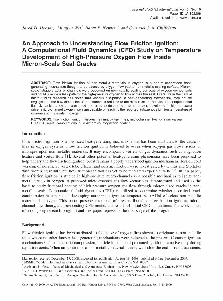
An experiment was conducted on a nylon cylinder valve seat to demonstrate the development ofsurface micron-scale cracks, as shown in Fig. 4. A new oxygen cylinder valve was opened and closedapproximately 100 times in order to expose the seat to a period of use and wear. Afterward, microscopicobservation of the seal revealed the presence of micron-scale cracks extending radially across the surfaceof the seal �Fig. 5�. Measurements of the cracks at various locations were obtained with a microscope toestablish typical crack widths on the nylon surface. The measurements are tabulated in Table 1.
The presence of micron-scale cracks on the surface of polymer seals could allow high-pressure oxygengas to flow across the sealing surface. This poses the question: Could oxygen flow confined to a micron-scale channel generate heat as it flows through these cracks? The presence of micron-scale cracks justifieda CFD study that investigated the temperature development of oxygen gas flowing through micron-sizedchannels.
Viscous Dissipation in Micro-channel Flows
The flow of fluid through micron-scale devices has gained interest recently due to advances in micro-machining technology, which has allowed for practical development of micro-electromechanical systemsand micro-fluidic devices. Micro-heat-exchangers that cool electronics, micro-pumps used to transportmedicine to patients, and micro-heat-engines that generate electrical power are examples of these devices�3–5�. The need to predict the fluid behavior in micro-fluidic devices is highly desirable to properlyvalidate designs pre-fabrication and has provided insight about the differences between micro-channelflows and large scale flows. Most of the research work involving temperature effects in micro-channelflows is related to heat transfer problems. Few research efforts have been directed at investigating viscous
FIG. 4—(a) Nylon seat removed from cylinder valve after the wear experiment; (b) 15� microscopeenlarged view of the nylon sealing surface.
FIG. 5—60� magnification of micron-scale cracking on the nylon cylinder valve seat shown in Fig. 4(b).

HOOSER ET AL. ON FLOW FRICTION IGNITION CFD MICROCHANNEL STUDY 5
dissipation effects and temperature development generated by a fluid flowing through micron-sized geom-etries.
Kundu and Cohen defined viscous dissipation as the rate of mechanical energy loss and a gain ofinternal energy through deformation of a fluid element �6�. The rate of viscous dissipation is proportionalto the square of the velocity gradients and is important where fluids undergo high shearing stresses. Theresulting heat generated by viscous dissipation can be intense; meteorites entering the Earth’s atmosphereoften burn up because of viscous dissipation heating that takes place between the air and meteor surface.
Researchers of viscous dissipation effects in micro-channels have suggested that the reduced flowdimension can increase the magnitude of viscous dissipation and frictional effects otherwise considerednegligible in macro-scale flows. Koo and Kleinstreuer have analytically investigated the effect of diameteron viscous dissipation �i.e., temperature rise� in liquid micro-tubes and found that tubes less than 100 �min diameter produced noticeable changes in fluid temperature, even for an isothermal wall condition �7�.The largest temperature rise reported was 25 K for a 20 �m diameter adiabatic tube with a Reynoldsnumber of 2,000. Beskok and Karniadakis noted that the viscous heating terms for micro-domains may notbe negligible �8�. They developed an analytical solution of a general micro-channel heat convectionproblem and showed an increase in the tangential temperature gradient along the surface of the pressure-driven channel as a function of increasing Mach number. The temperature profiles of their micro-channelswith insulated surfaces produced the largest temperatures at the wall where shear stresses �i.e., viscousdissipation� dominated. To investigate frictional heating at the channel wall Wu et al. constructed a 20�2�4,400-micron channel with integrated temperature sensors �9�. Nitrogen gas at 1.87 and 2.10 MPawas forced through the thermally isolated channel. They reported that each temperature sensor reading waslower than the ambient gas temperature �297.87 K�, but a sensor placed in between the inlet and outlet ofthe channel read the highest temperature �297.65 K�. They attributed the highest temperature reading tofrictional heating generated by the high-pressure gas flow.
Continuum Limit Considerations for Micro-channel Flow
Investigating pressure-driven oxygen flow through micron-scale cracks requires an understanding of fluidbehavior when the characteristic dimension of the flow passage approaches the mean free path of theoxygen molecule. The mean free path describes the average distance traveled by a molecule beforeimpacting another molecule. For oxygen, the mean free path is 2.98e−10 m which is only one order ofmagnitude different when compared to the length scale of the micron-scale cracks observed on the nylonseal in Fig. 5 �20 �m� �10�. For this reason, it was important to consider the limitations of continuumtheory.
Continuum theory considers a continuous fluid and assumes all dependent variables like temperature,velocity, and density can be described as average quantities over a region that is large in comparison to thefluid particles but small in relation to the scale of the physical problem being described �11�. The Knudsennumber �Kn� is used to distinguish continuum flows from free molecular flows �i.e., non-continuum flows�.Table 2 outlines the difference between continuum and free molecular flows based on the Knudsennumber.
The Knudsen number is defined as the ratio between the mean free path of the fluid molecule and thecharacteristic flow dimension
Kn =�
�1�
TABLE 1—Micron cracks measurements of nylon cylinder valve seat.
Nylon Seal Crack Measurement Crack Width ��m�D1 20.4
D2 17.9
D3 16.0
D4 17.9
D5 30.6
Average width 20.6
L

6 JOURNAL OF ASTM INTERNATIONAL
� =kT
�2�p�2�2�
where:�=mean free path of the molecules,L=characteristic length,�=molecular diameter,k=Boltzman constant,T=temperature, andp=pressure �5�.Using Eq 2, a range of Knudsen numbers were calculated for different micro-crack widths for the
expected temperature and pressure conditions at the inlet and outlet of the cracks5 given in Table 3.By varying the widths of the cracks from 1–200 �m and using the pressure and temperature values
in Table 3, the Knudsen number was compared at the inlet and outlet of the cracks in Fig. 6�a�. At the inlet,the Knudsen number was within the continuum limit for crack sizes larger than approximately 1 �m. Atthe outlet, the Knudsen number was greater than 0.001 for both temperatures, implying a non-continuumcondition.
5Because oxygen tanks are typically filled with 13.8 MPa oxygen, this value was used as the inlet crack pressure. The pressure at the outlet of thecrack was taken as atmospheric �0.1 MPa�. The upper limit of temperature was chosen as 500 K because this is the nominal AIT of nylon in
TABLE 2—Knudsen number and corresponding flow regimes.
Knudsen Number Flow Regime
Kn�0.001 Continuum
0.001�Kn�10 Slip/Transitional
Kn�10 Free Molecular
TABLE 3—Expected values of pressure and temperature at the inletand outlet of the micron-cracks.
Pressure, MPa Temperature, K
Inlet 13.8 298–500
Outlet 0.1 298–500
FIG. 6—(a) Range of Knudsen numbers varying the channel width from 1–200 �m with inlet conditionsof 13.7 MPa, and outlet conditions of 101.325 kPa at two temperatures; 298 and 500 K; (b) preliminaryCFD centerline pressure distribution for a 20 �m width channel and the effective outlet pressure, 3.4MPa.
oxygen.

HOOSER ET AL. ON FLOW FRICTION IGNITION CFD MICROCHANNEL STUDY 7
However, preliminary CFD simulations indicated that the gas near the channel outlet maintained ahigher pressure than the 0.1 MPa outlet boundary pressure. The centerline CFD pressure distribution for a20 �m channel is shown in Fig. 6�b� highlighting the effective outlet pressure maintained near the channeloutlet, approximately 3.4 MPa. Using the effective outlet pressure, the Knudsen number was withincontinuum limits at the outlet for crack sizes larger than approximately 8 �m �Fig. 7�. Although gasexpansion did not occur instantaneously at the outlet boundary, a major reduction in pressure existed afterthis point and the entire length of the micro-channel remained pressurized well above ambient pressure.Therefore, the gas flow up to the outlet boundary was expected to meet continuum conditions. Additionalwork is required to determine the crack size and channel pressure relationship with continuum flow.
Computational Fluid Dynamics Simulations with Fluent®
A steady two-dimensional turbulent compressible gas flow in a micro-channel was simulated using theCFD software, Fluent®. Temperature development in the micro-channels was investigated by varying thechannel width, W, from 10–300 �m and length, L, from 500–10,000 �m. A schematic of the channelgeometry is shown in Fig. 8.
Pressure-driven flow, consistent with an oxygen tank source feeding the inlet of the channel andexiting to atmosphere, was used to define the inlet and outlet boundary conditions of the model. Pressureboundaries were specified as 13.8 MPa and 0.1 MPa for the inlet and outlet, respectively, and gas tem-perature boundaries were maintained at 298 K. Boundary conditions at the channel walls were non-slipand adiabatic, which did not allow for any heat transfer to or from the surroundings. Heat transfer wouldnormally occur in real micro-channel flows, but the adiabatic wall condition was chosen to readily com-pare heat development within each micro-channel flow.
A typical straight micro-channel configuration mesh is shown in Fig. 9. The same geometry andmeshing approach was used for an enlarged inlet and outlet channel configuration by adding an enlargedregion connected to the inlet and outlet of the channel �controlled by the channel height, h, illustrated inFig. 10�. To reduce computational time, only one-half the channel was simulated utilizing a symmetricboundary at the channel centerline. This configuration allowed for modeling of the oxygen gas flowentering and exiting the channel and resembles a closer representation of the real micro-channel crack flow
FIG. 7—Range of Knudsen numbers at the channel effective outlet pressure, 3.4 MPa.
situation.

8 JOURNAL OF ASTM INTERNATIONAL
Computational Fluid Dynamics Grid Independence Study
The simulation results depend on the size of the computational mesh chosen, especially at boundarieswhere large gradients are present in the flow field. To ensure the results obtained for the micro-channelsimulations were independent of the computational mesh, it was necessary to perform several simulationswith different mesh sizes for a single micro-channel geometry.
A 40 �m height by 1,500 �m length channel was chosen for the mesh independence study. Aconverged mesh was established when additional grid points added to the computational mesh producedless than a 0.2 % change in the simulation results. The computational mesh size was defined by grid points,which created grid intervals along a micro-channel edge. For example, if N grid intervals were desired
FIG. 8—Two-dimensional micro-channel crack model for the Fluent® CFD study.
FIG. 9—Typical straight micro-channel configuration mesh.
FIG. 10—Micro-channel configuration mesh with an enlarged inlet and outlet region attached.

HOOSER ET AL. ON FLOW FRICTION IGNITION CFD MICROCHANNEL STUDY 9
along an edge, N+1 grid points are required along that edge. The computational mesh size was denoted bythe number of grid intervals along the height and length directions �e.g., 50�100�. Mesh independencewas evaluated using velocity and temperature results obtained for each mesh refinement size at the channelmidplane �a station located exactly between the channel inlet and outlet�. The successive grid refinementsand results for centerline velocity and temperature are given in Table 4. Refinement Level 7 was selectedas the converged mesh because additional refinements �Levels 8 and 9� produced less than a 0.2 % changein the centerline velocity and wall temperature values.
Mesh Sizes for Different Channel Heights
To apply the converged mesh established for the 40 �m channel to channels of different heights, separatemeshing techniques were used. This was dependent on whether the channel height was larger or smallerthan the 40 �m height channel. If the channel height was less than 40 �m, the same mesh size estab-lished for the 40 �m channel mesh was used.6 This was justified by assuming conservatively that the sameamount of mesh cells within a smaller channel height dimension would achieve the same or betterresolution demonstrated for the 40 �m converged mesh. If the channel height was larger than 40 �m, theboundary grid resolution was kept the same as the 40 �m converged mesh but additional grids were addedto the center region of the channel to make up the increase in height. This approach limited the compu-tational time required to perform mesh independence studies on all channel heights simulated. Table 5shows the combination of micro-channel heights and lengths simulated with mesh sizes used.
Fluent® Simulation Results
The Fluent® simulation results are presented for both the straight and enlarged inlet and outlet attachmentmicro-channel configurations. Typical results for the effect of channel height and channel length on themidplane velocity and temperature profiles are given first followed by average wall and fluid temperaturescompared against the dimensionless micro-channel aspect ratios, L /h, and Reynolds numbers, Re.
The effect of channel height and channel length on midplane velocity and temperature profiles areshown in Figs. 11–14. Small channel heights tend to reduce the magnitude of velocity and increase themagnitude of fluid temperature at the channel midplane. This result supports the increased influence ofviscous forces generated by the micro-channel wall for smaller height channels; the closer the channelwalls are to each other �small height distance� the more effect viscous forces will have across the smallchannel height. Conversely, channels with large heights �walls separated by a greater distance� wereinfluenced less by viscous forces, as seen by the greater magnitude in midplane velocity and reducedmidplane temperatures. The magnitude differences between midplane velocity and temperatures are no-ticeably different. Comparing the 10 �m and 300 �m height channels, centerline velocity and tempera-ture values differed by 105 m/s and 26 K, respectively. A similar effect was seen when the channel lengthwas varied with a constant channel height �Figs. 13 and 14�. Long channel lengths tended to reduce themagnitude of the velocity and increase the magnitude of the fluid temperature at the channel midplane.This result corresponds to the additional friction force applied to the fluid flowing through a channel of
6 ®
TABLE 4—Mesh refinements and corresponding velocity and temperature data.
Refinement Level Mesh Size Midplane Velocity �m/s� Midplane Wall Temperature �K�
1 10�250 246.247 286.828
2 20�250 252.472 290.117
3 40�250 248.142 291.456
4 40�500 247.857 291.461
5 60�500 247.460 292.315
6 60�750 247.384 292.314
7 80�500 247.551 292.914
8 80�750 247.470 292.915
9 90�500 247.926 292.985
Only 50 mesh cells were used for the 10 �m height channels because additional cells would result in a failed grid when imported into Fluent .

10 JOURNAL OF ASTM INTERNATIONAL
longer length. Conversely, channels of shorter length have a reduced amount of frictional force appliedalong the wall and correspondingly have higher velocity and lower temperature magnitudes at the channelmidplane. The differences in magnitude are again noticeably different. Comparing the 0.5 mm and 10 mmlength channels, centerline velocity and temperature values taken from the midplane profiles differ by 126m/s and 25 K, respectively.
The non-dimensional aspect ratio, L /h, and Reynolds number, Re, were chosen to identify fluidtemperature trends throughout the range of micro-channel sizes simulated. The relationship betweenmicro-channel aspect ratio and average wall and fluid temperatures is shown in Figs. 15 and 16. Micro-channels with short heights and long lengths �i.e., large aspect ratios� maintain higher average wall andfluid temperatures than channels with large heights and short lengths �i.e., small aspect ratios�. This resultcorresponds to the previously presented channel midplane results in which channels with short heights andlong lengths had larger temperature magnitudes than channels with large heights and short lengths. Therelationship trend between aspect ratio and fluid temperature tends to flatten for aspect ratios larger than100. This indicates an approach to an asymptotic limit, corresponding to approximately 290 K and 297 Kfor average fluid temperature and average wall temperatures, respectively. This result suggests that theupper limit of fluid temperature increase was approached with the micro-channel sizes simulated in thisstudy. Also, channels with the same aspect ratio but different height/length combinations had comparablefluid temperatures. This indicated a strong correlation between channel aspect ratio and the temperaturewithin the micro-channel flow field. The average fluid and wall temperatures were also compared against
TABLE 5—Micro-channel simulation test matrix and mesh sizes used.
Channel Height ��m�
Channel Length ��m�
500 1,500 3,000 5,000 10,000
10 50�167 50�500 50�1,000 50�1,66720 80�167 80�500 80�1,000 80�1,667 80�3,33440 80�167 80�500 80�1,000 80�1,66760 94�167 94�500 94�1,000 94�1,66780 108�167 108�500 108�1,000 108�1,667100 122�167 122�500 122�1,000 122�1,667150 157�167 157�500 157�1,000 157�1,667200 192�167 192�500 192�1,000 192�1,667300 262�167 262�500 262�1,000 262�1,667
FIG. 11—Micro-channel height effect on the midplane velocity profile.

HOOSER ET AL. ON FLOW FRICTION IGNITION CFD MICROCHANNEL STUDY 11
the channel Reynolds numbers in Figs. 17 and 18. As the Reynolds number decreases, average fluid andwall temperatures tend to increase, corresponding to a reduction in channel height and an increase inchannel length. Because the Reynolds number is a ratio of the inertial and viscous forces in a flowing fluid,this result suggested that the inertial forces diminished with decreasing channel height and increasingchannel length, thus allowing viscous effects to become more prominent �i.e., higher average fluid andwall temperatures due to friction at the channel wall�.
An unusual trend was observed for the average wall temperature results obtained for channels with theinlet and outlet regions attached as shown in Figs. 16 and 18. Unlike the smooth trend observed for theaverage fluid temperature results, the average wall temperature trend was not smooth and did not correlatewell with different aspect ratios and Reynolds numbers. This unusual trend can be attributed to thepossible influence of the inlet and outlet regions on the wall temperatures, and the difficulty in obtaininga converged solution for this channel configuration. The addition of the inlet and outlet regions affected thestability of the solution process and many times would diverge to an erroneous solution. Converging to a
FIG. 12—Micro-channel height effect on the midplane temperature profile.
FIG. 13—Micro-channel length effect on the midplane velocity profile.

12 JOURNAL OF ASTM INTERNATIONAL
steady-state condition may not have been achieved with this configuration and further work is needed tofully understand the effect of the inlet and outlet attachments on the micro-channel fluid temperature.
Finally, Mach number contours beyond the outlet of a 100 �m height channel are shown in Fig. 19.The Mach number contours suggest that the exiting flow expands supersonically to the ambient atmo-spheric air. This is an interesting result because the high-speed flow leaving the channel outlet may be ofinterest to future studies.
Conclusions
A new approach to understanding flow friction ignition that explores whether gas flow could generate theheat required to ignite non-metallic materials in oxygen was described. Oxygen fires attributed to flowfriction ignition were presented. A proposed micro-channel gas flow scenario was demonstrated for the
FIG. 14—Micro-channel length effect on the midplane temperature profile.
FIG. 15—Micro-channel aspect ratio and average fluid temperature.

HOOSER ET AL. ON FLOW FRICTION IGNITION CFD MICROCHANNEL STUDY 13
types of non-metallic seals that were identified as fire origin. Micro-channel gas flow was used as the basisto study frictional heating of gas flow through micron-sized cracks in oxygen seals. CFD simulations wereshown to be applicable to the study of crack wall temperatures developed by the high-pressure oxygen gasflow and to investigate the heat development within micron-scale channels �i.e., cracks�. For the range ofmicro-channels simulated �h=10–300 �m and L=0.5–10 mm�, viscous effects were most dominant forchannels with large aspect ratios and small Reynolds numbers. Average fluid temperatures were approxi-mately 30 K higher for channels with large aspect ratios and small Reynolds numbers than were theaverage fluid temperatures for channels with small aspect ratios and large Reynolds numbers. Correspond-ingly, the average wall temperatures were approximately 4 K higher for channels with large aspect ratiosand small Reynolds numbers than they were for channels with small aspect ratios and large Reynolds
FIG. 16—Micro-channel aspect ratio and average wall temperature.
FIG. 17—Micro-channel Reynolds number and average fluid temperature.

14 JOURNAL OF ASTM INTERNATIONAL
numbers. Although temperatures developed were noticeably different for channels with large aspect ratios,all average fluid and wall temperatures were well below the temperature required to ignite nylon in oxygen�approximately 500 K�. Seal cracking probably occurs frequently in nylon seals that are used repeatedly inoxygen systems. Also, if temperatures developed in micro-channel cracks were high, oxygen fires wouldbe expected to occur more frequently. These results suggest that the likelihood of an oxygen fire occurringdue to an oxygen leak through a micro-channel crack alone is unlikely and coincides with the rareoccurrence of oxygen fires observed in industry. The micro-channel cracks may be one factor that con-tributes to oxygen fires attributed to flow friction ignition. Other unknown factors or a combination ofdifferent factors may join together to explain flow friction ignition in oxygen systems.
FIG. 18—Micro-channel Reynolds number and average wall temperature.
FIG. 19—Mach number contours beyond the outlet of a 100 �m height channel.
HOOSER ET AL. ON FLOW FRICTION IGNITION CFD MICROCHANNEL STUDY 15
Future Work
The Fluent® simulation result of supersonic flow at the outlet of the micro-channels may allow for shockwave development and the opportunity for stagnation heating downstream of the channel outlet. Therandom nature of crack development in nylon seals could provide a configuration that emulates aconverging/diverging nozzle �increasing the likelihood of supersonic flow� and that allows nylon obstruc-tions to stagnate the high-speed flow exiting the crack outlet. The heating at these stagnation points maybe significant and provokes further investigation as an extension of the high-pressure micro-channel flowfriction ignition theory. The identification of micro-channel cracks and the capability for supersonic flow,as simulated by Fluent®, provides a significant contribution and basis for future work.
Finally, interesting information related to localized heating of fatigue crack tips in nylon polymers wasdiscovered in the literature �12�. A hydraulic fatigue test machine induced fatigue cracks in Nylon 6/6 andcrack-tip temperatures were recorded with a thermal imaging camera. For one test sample, the localizedcrack-tip temperature was reported as 55°C and was approximately 30°C higher than the nylon tempera-ture far from the crack-tip region. Future testing may utilize the heat generated at the tip of a propagatingnylon crack as another means to explain flow friction ignition of non-metal seals in oxygen.
Acknowlegments
This flow friction ignition research effort was sponsored by Wendell Hull and Associates, Inc. in part tofulfill the requirements of a master’s degree at New Mexico State University �13�. Special thanks to Dr.Wendell Hull and the great people of Wendell Hull & Associates, Inc. for their generous support of thisproject. The writers would like to thank Dr. Chunpei Cai and Dr. Ian Leslie for their contributions to thiswork.
References
�1� Stong, C. L., The Scientific American Book of Projects for the Amateur Scientist, Simon and SchusterPublishing, New York, NY, 1960, pp. 514–520.
�2� Gallus, T. D. and Stoltzfus, J. M., “Flow Friction Fire History and Research,” J. ASTM Int., Vol. 3,No. 9, 2006, Paper ID JAI13543.
�3� Ho, C. M. and Tai, T. C., “Micro-Electro-Mechanical Systems �MEMS� and Fluid Flows,” Annu. Rev.Fluid Mech., Vol. 30, 1998, pp. 579–612.
�4� Epstein, A. H. and Senturia, S. D., “Macro Power from Micro Machinery,” Science, Vol. 276, 1997,p. 1211.
�5� Gad-el-Hak, M., “The Fluid Mechanics of Microdevices—The Freeman Scholar Lecture,” ASME J.Fluids Eng., Vol. 121, 1999, pp. 5–33.
�6� Kundu, P. K. and Cohen, I. M., Fluid Mechanics, 3rd ed., Elsevier Academic Press, New York, NY,2004, pp. 105–106.
�7� Koo, J. and Kleinstreuer, C., “Liquid Flow in Microchannels: Experimental Observations and Com-putational Analyses of Microfluidics Effects,” J. Micromech. Microeng., Vol. 13, 2003, pp. 568–579.
�8� Beskok, A. and Karniadakis, G. E., “Simulation of Heat and Momentum Transfer in ComplexMicrogeometries,” J. Thermophys. Heat Transfer, Vol. 8, 1994, pp. 647–655.
�9� Wu, S., Mai, J., Zohar, Y., Tai, Y. C., and Ho, C. M. “A suspended microchannel with integratedtemperature sensors for high-pressure flow studies,” Proceedings of the 11th IEEE Workshop onMicro Electro Mechanical Systems, 1998, pp. 87–92.
�10� Weast, R.C., Handbook of Chemistry and Physics, 54th ed., CRC Press, Cleveland, OH, 1974, p. 195.�11� Munson, B. R., Young, D. F., and Okiishi, T. H., 2002, Fundamentals of Fluid Mechanics, John
Wiley and Sons, Inc., New York, NY, p. 4.�12� Wyzgoski, M. G., Novak, G. E., and Simon, D. L., “Fatigue Fracture of Nylon Polymers: Part 1
Effect of Frequency,” J. Mater. Sci., Vol. 25, 1990, pp. 4501–4510.�13� Hooser, J. D., “A High-Pressure Driven Compressible Gas Flow Study Inside a Two-Dimensional
Uniform Microchannel,” MS Thesis, New Mexico State University, 2009.