Embed Size (px)
Citation preview
2008 International IEEE Symposium on Precision Clock Synchronization (ISPCS) for Measurement, Control and Communication Ann Arbor, U.S.A Sept. 22-26, 2008.
An Application Framework for the IEEE 1588 Standard
Eugene Y. Song, Kang Lee National Institute of Standards and Technology
100 Bureau Drive, Stop 8220 Gaithersburg, Maryland 20899-8220 USA
E-mail: [email protected], [email protected] Abstract: This paper introduces an application framework for the Institute of Electrical and Electronics Engineers (IEEE) 1588 standard. This application framework, developed at the National Institute of Standards and Technology (NIST), consists of five layers: hardware layer, operating system layer, middleware and tools layer, IEEE 1588 layer, and application layer. A prototype application system has been developed based on the established IEEE 1588 application framework using the Unified Modeling Language (UML) tool. A case study of the IEEE 1588 Delay Request-Response mechanism based on the application framework is presented. The object-oriented application framework can ease integration and simplify the development of new IEEE 1588 applications by reducing the amount of time and errors to design and develop the IEEE 1588 standard infrastructure. Another benefit of this application framework is to enable developers to achieve standards compliance more readily. Keywords: Application framework, IEEE 1588, Object-oriented framework, UML
I. INTRODUCTION
The Institute of Electrical and Electronics Engineers (IEEE) 1588 standard defines a precision time protocol (PTP) enabling precise synchronization of clocks in measurement and control systems implemented using distributed architectures comprised of evolving technologies in network communication, localized computing and distributed objects [1-2]. The IEEE 1588 protocol is applicable to distributed measurement and control systems consisting of two or more nodes communicating over a network. Figure 1 shows an example of clock synchronization based on a packet network. The slave clocks can synchronize with the master clock through packet network communications. Most measurement systems share similarities in the fundamental components. However, these systems are often developed from scratch, without reusing the available designs and implementations [3]. Since these designs are also costly to implement, object-oriented development (OOD) promises to increase code reuse while reducing development time and cost. A framework is a reusable application foundation that can be customized for a particular customer application [4, 5]. An object-oriented framework provides an important enabling technology for reusing software components [6]. Object-oriented frameworks allow reusing analysis, design, implementation,
and testing for applications within a certain domain or a certain family of problems [7]. The object-oriented framework focuses on code and design reuse. Hence the object-oriented development methodology plays a key role in the design of the framework. The object-orient methodology, when applied to application frameworks, enables higher productivity and shorter time-to-market of application development.
Packet Network
MasterClock
SlaveClock
SlaveClock
SlaveClock
Packet Network
MasterClock
SlaveClock
SlaveClock
SlaveClock
Fig. 1. Example of clock synchronization.
The Unified Modeling Language (UML) was designed to
be compatible with the leading object-oriented software development methods [8]. UML is a powerful tool for object-oriented modeling and design, and development of complex software systems. Developing an application framework for the IEEE 1588 standard using UML significantly reduces the development time of IEEE 1588 applications. The current implementation focuses on the IEEE 1588 layer and application layer. Section II discusses related works. In section III, an application framework for the IEEE 1588 standard is described. Section IV shows a prototype system of an IEEE 1588 application. The conclusion is provided in Section V.
II. RELATED WORKS
The use of application frameworks is a promising approach for reusing and integrating proven software designs and implementations in order to reduce the cost and improve the quality of software. The framework concept can be found in Smalltalk** systems, which has been attributed as the first widely used framework [9]. MacApp was Apple Computer's primary object-oriented application framework for the Mac operating system during the 1990s [10]. An object-oriented framework is also used for developing distributed applications [11]. Object-oriented real-time frameworks have been used for building distributed real-time control systems in robotics and automation [12]. A framework-based approach to real-time development is used for code
978-1-4244-2275-3/08/$25.00 ©2008 IEEE 23
2008 International IEEE Symposium on Precision Clock Synchronization (ISPCS) for Measurement, Control and Communication Ann Arbor, U.S.A Sept. 22-26, 2008. generation in the Rhapsody UML tool [13]. An object-oriented framework is used for developing distributed manufacturing architectures [14]. Roberts & Johnson describe the evolution of a framework as starting from a white-box framework that is reused by sub-classing, and developing into a black-box framework that is mostly reused through parameterization [15]. Hayase introduced a three-view model for developing object-oriented frameworks. The three-view model consists of a domain analysis view, a layer view, and a mechanism view. The layer view is used to divide a framework into three layers: an infrastructure layer, a generic layer, and a domain layer [16]. Bosch describes a framework consisting of a core framework design, and its associated internal increments with accompanying implementation, such as framework internal increments and application specific increment [17]. The verifiable embedded real-time application framework (VERTAF) is an object-oriented application framework for embedded real-time systems [18]. An object-oriented application framework for the IEEE 1451.1 standard has been established [19]. Specifier, extractor, scheduler, allocator, and generator (SESAG) is an object-oriented application framework for real-time systems [20]. Becker introduces an object-oriented framework for the development of real-time industrial automation systems [21]. In summary, object-oriented application frameworks have been widely used in many different domain and cross-domain applications, especially in distributed real-time measurement and control systems.
III. APPLICATION FRAMEWORK FOR IEEE 1588 STANDARD
A. Architecture of Application Framework for IEEE 1588 Standard
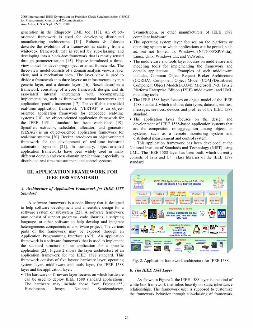
A software framework is a code library that is designed to help software development and a reusable design for a software system or subsystem [22]. A software framework may consist of support programs, code libraries, a scripting language, or other software to help develop and integrate heterogeneous components of a software project. The various parts of the framework may be exposed through an Application Programming Interface (API). An application framework is a software framework that is used to implement the standard structure of an application for a specific application [23]. Figure 2 shows the layer architecture of an application framework for the IEEE 1588 standard. This framework consists of five layers: hardware layer, operating system layer, middleware and tools layer, the IEEE 1588 layer and the application layer. • The hardware or firmware layer focuses on which hardware
can be used to deploy IEEE 1588 standard applications. The hardware may include those from Freescale**, Hirschmann, Imsys, National Semiconductor,
Symmetricom, or other manufacturers of IEEE 1588 compliant hardware.
• The operating system layer focuses on the platform or operating system to which applications can be ported, such as, but not limited to, Windows (NT/2000/XP/Vista), Linux, Unix, Windows CE, and VxWorks.
• The middleware and tools layer focuses on middleware and modeling tools for implementing the framework and domain applications. Examples of such middleware includes, Common Object Request Broker Architecture (CORBA), Component Object Model (COM)/Distributed Component Object Model(DCOM), Microsoft .Net, Java 2 Platform Enterprise Edition (J2EE) middleware, and UML modeling tools.
• The IEEE 1588 layer focuses on object model of the IEEE 1588 standard, which includes data types, datasets, entities, messages, services, devices and profiles of the IEEE 1588 standard.
• The application layer focuses on the design and development of IEEE 1588-based application systems that are the composition or aggregation among objects in systems, such as a remote monitoring system and distributed measurement and control system.
This application framework has been developed at the National Institute of Standards and Technology (NIST) using UML. The IEEE 1588 layer has been built, which currently consists of Java and C++ class libraries of the IEEE 1588 standard.
IEEE 1588 API(C/C++/C#, Java)
IEEE 1588 Data Types
IEEE 1588 Datasets
IEEE 1588 Entities
IEEE 1588 Messages
IEEE 1588 Services
IEEE 1588 Devices
IEEE 1588 Applications in Java & C/C++/C#(IEEE1588 Objects & Non-IEEE1588 Objects)
Middleware & Tools
CORBA, COM/DCOM, MS .NetJava RMI, JMS, Java.net.* J2EE
UML Tools
Profile 1 Profile 2 Profile 3 Profile 4
Operating Systems(Windows
Vista/XP/2000, Windows CE,
Linux, Unix, VxWorks)
Hardware
Freescale
HirschmannNational Semiconductor National
Instrument
Meinberg
SymmetricomWestermoOnTime
TeletronicsZurich
University
Imsys
IEEE 1588 API(C/C++/C#, Java)
IEEE 1588 Data Types
IEEE 1588 Datasets
IEEE 1588 Entities
IEEE 1588 Messages
IEEE 1588 Services
IEEE 1588 Devices
IEEE 1588 Applications in Java & C/C++/C#(IEEE1588 Objects & Non-IEEE1588 Objects)
IEEE 1588 Applications in Java & C/C++/C#(IEEE1588 Objects & Non-IEEE1588 Objects)
Middleware & Tools
CORBA, COM/DCOM, MS .NetJava RMI, JMS, Java.net.* J2EE
UML Tools
Profile 1 Profile 2 Profile 3 Profile 4
Operating Systems(Windows
Vista/XP/2000, Windows CE,
Linux, Unix, VxWorks)
Hardware
Freescale
HirschmannNational Semiconductor National
Instrument
Meinberg
SymmetricomWestermoOnTime
TeletronicsZurich
University
Imsys
Fig. 2. Application framework architecture for IEEE 1588. B. The IEEE 1588 Layer
As shown in Figure 2, the IEEE 1588 layer is one kind of white-box framework that relies heavily on static inheritance relationships. The framework user is supposed to customize the framework behavior through sub-classing of framework
24

2008 International IEEE Symposium on Precision Clock Synchronization (ISPCS) for Measurement, Control and Communication Ann Arbor, U.S.A Sept. 22-26, 2008. classes. This layer mainly focuses on the object model of IEEE 1588, which consists of data types, datasets, entities, messages, services, devices and profiles of the IEEE 1588 standard [24-25].
B.1 Data Types of IEEE 1588
The IEEE 1588 data types consist of primitive data types and derived data types. The primitive data types include boolean, integers (signed and unsigned 8 bits, 16 bits, and 32 bits), and octet (one byte). The primitive data types can be mapped into the primitive data types of the C/C++/Java/C# programming language, or defined as an individual class. The derived data types of the IEEE 1588 standard are derived from these primitive data types. The derived data types of IEEE 1588, including arrays of primitive data types, enumerations, and structs, can be also defined as an individual class. B.2 Datasets of IEEE 1588
A Precision Time Protocol (PTP) clock has two types of data sets: clock data sets and port data sets. The clock data set describes the attributes of clocks, such as default dataset, current dataset, time property dataset, and parent dataset. The port data sets describe the attributes of clock ports. There are three kinds of port datasets defined in IEEE 1588, including port data set of ordinary clock, port data set of boundary clock, and port data set of transparent clock.
PTPMessage
GeneralMessageEventMessage
originTimestamp:Timestamp
Sync Pdelay_Req
Pdelay_Resp
Signaling
Management
Announce
Delay_Resp Pdelay_Resp_Follow_Up
Delay_Req
Follow_Up
1suffix
Suffix
1suffix1messageHeader 1messageHeader
MessageHeader
transportSpecific :NibblemessageType:MessageTypeversionPTP:UInteger4messageLength:UInteger16domainNumber:UInteger8Flags:OctetArraycorrectionField:Integer64sourcePortIdentity:PortIdentitysequenceId:UInteger16controlField:UInteger8logMessageInterval:Integer8
Announce
originTimestamp:TimestampcurrentUTCOffset:Integer16timeSource:Enumeration8stepsRemoved:UInteger16grandmasterIdentity:ClockIdentitygrandmasterClockQuality:ClockQualitygrandmasterPriority1:UInteger8grandmasterPriority2:UInteger8
Fig. 3. PTP message.
B.3 Messages of IEEE 1588
All PTP-related communications occur via PTP messages. The PTP messages have a header, body and suffix. Figure 3 shows the class definition of PTP messages. The
PTPMessage can be subdivided into two types: EventMessage and GeneralMessage, which can inherit all the attributes of PTPMessage. The EventMessage with a timestamp attribute can be subdivided into Sync, Delay_Req, Pdelay_Req, and Pdelay_Resp messages, which inherit the timestamp attribute from EventMessage. The GeneralMessage can be subdivided into Announce, Follow_Up, Delay_Resp, Management, Signaling, and Pdelay_Resp_Follow_Up messages. Each specific PTP message inherits the common attributes (message header and suffix) from the general PTP message, and also has its own attributes. B.4 PTP Services for IEEE 1588
Fig. 4 shows the definition of PTPService that we propose. The PTPService can be divided into EventService and GeneralService. The EventService includes Sync, DelayRequest, PDelayRequest and PDelayResponse services. The GeneralService includes Announce, FollowUp, DelayResponse, PDelayResponseFollowUp, Management, and Signaling services. Each PTP individual service is an operation with corresponding arguments (messages).
PTPService
«Interface»
EventService«Interface»
Sync(sync:Sync):UInteger16DelayRequest(delayRequest:Delay_Req):UInteger16PDelayReponse(pDelayResposne:Pdelay_Resp):UInteger16PDelayRequest(pDelayRequest:Pdelay_Req):UInteger16
GeneralService«Interface»
Announce(announce:Announce):UInteger16DelayResponse(delayResponse:Delay_Resp):UInteger16PDelayResponseFollowUp(pDelayResponseFollowUp:Pdelay_Resp_Follow_Up):UInteger16Signaling(signaling:Signaling):UInteger16Management(management:Management):UInteger16FollowUp(followUp:Follow_Up):UInteger16
Fig. 4. PTP services.
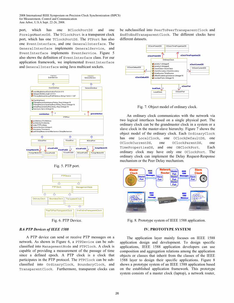
B.5 PTP Port of IEEE 1588
Each port of the PTP ordinary, boundary, or transparent clock supports the event interface and general interface. The event interface is used to send and receive event messages, which are time-stamped based on the value of the local clock. The general interface is used to send and receive general messages, such as Announce and Management. A port may implement both the Delay Request-Response mechanism and Peer Delay mechanism, but only one mechanism is active at any time. Figure 5 shows the definition of the PTPPort class. The PTPPort can be subdivided into OClockPort, BClockPort, and TClockPort, which can inherit all the attributes of PTPPort. The OClockPort is an ordinary clock port, which has one OClockPortDS and one ForeignMasterDS. The BClockPort is a boundary clock
25
2008 International IEEE Symposium on Precision Clock Synchronization (ISPCS) for Measurement, Control and Communication Ann Arbor, U.S.A Sept. 22-26, 2008.
port, which has one BClockPortDS and one ForeignMasterDS. The TClockPort is a transparent clock port, which has one TClockPortDS. The PTPort has also one EventInterface, and one GeneralInterface. The GeneralInterface implements GeneralService, and EventInterface implements EventService. Figure 5 also shows the definition of EventInterface class. For our application framework, we implemented EventInterface and GeneralInterface using Java multicast sockets.
PTPPort
portAddress:PortAddressportIdentity:PortIdentitystate:PTPPortStateversionNumber:UInteger4timestamp:TimestamppathDelayMeasurementMechanism:DelayMechanism
GeneralService«Interface»
OClockPort
1oClockPortDS
1oClockPortDS
OClockPortDS
1foreignMasterDS
ForeignMasterDS
1foreignMasterDS
BClockPort
1bClockPortDS 1bClockPortDS
BClockPortDS
1foreignMasterDS
1foreignMasterDS
ForeignMasterDS
TClockPort
TClockPortDS
1tClockPortDS 1tClockPortDS
1 generalInterface
GeneralInterface
1 generalInterface1eventInterface 1eventInterface
EventInterface
eventMsgMulticastDestinationPort:int=319datagramBufferLength:int=512PrimaryMulticastGroupIPv4IPAddress:String="224.0.1.129"
EventInterface()PDelayRequest(pdelayreq:Pdelay_Req):UInteger16PDelayResponse(pdelayResp:Pdelay_Resp):UInteger16DelayRequest(delayReq:Delay_Req):UInteger16Sync(sync:Sync):UInteger16
EventService«Interface»
Fig. 5. PTP port.
BoundaryClock
EndToEndTransparentClock
OrdinaryClock
PeerToPeerTransparentClock
ManagementNode
PTPDevice
TransparentClock
PTPClock
Fig. 6. PTP Device.
B.6 PTP Devices of IEEE 1588
A PTP device can send or receive PTP messages on a network. As shown in Figure 6, a PTPDevice can be sub-classified into ManagementNode and PTPClock. A clock is capable of providing a measurement of the passage of time since a defined epoch. A PTP clock is a clock that participates in the PTP protocol. The PTPClock can be sub-classified into OrdinaryClock, BoundaryClock, and TransparentClock. Furthermore, transparent clocks can
be subclassified into PeerToPeerTransparentClock and EndToEndTransparentClock. The different clocks have different datasets.
OrdinaryClock
priority1:UInteger8priority2:UInteger8clockClass:ClockClassclockAccuracy:ClockAccuracytimeSource:TimeSourceoffsetScaledLogVariance:UInteger16numberPorts:UInteger16
LocalClock
1localClock 1localClock
1
oClockDefaultDS
OClockDefaultDS1
oClockDefaultDS
1
oClockCurrentDS
OClockCurrentDS1
oClockCurrentDS
OClockParentDS
1oClockParentDS
1oClockParentDS
1oClockTimePropertiesDS
OClockTimePropertiesDS
1oClockTimePropertiesDS
1oClockPort
1oClockPort
OClockPort
Fig. 7. Object model of ordinary clock.
An ordinary clock communicates with the network via two logical interfaces based on a single physical port. The ordinary clock can be the grandmaster clock in a system or a slave clock in the master-slave hierarchy. Figure 7 shows the object model of the ordinary clock. Each OrdinaryClock has one LocalClock, one OClockDefaultDS, one OClockCurrentDS, one OClockParentDS, one TimePropertiesDS, and one OBClockPort. Each ordinary clock may have only one OClockPort. The ordinary clock can implement the Delay Request-Response mechanism or the Peer Delay mechanism.
Slave
ClockSlavePort
MasterPort
MasterClock
SlavePort
MasterPort
MasterPort
MasterPort
NetworkRouter
IEEE 1588
Messages
IEEE 1588
Messages
IEEE 1588
Message
IEEE 1588
Message
SlaveClock
SlavePort
MasterPort
MasterClock
SlavePort
MasterPort
MasterPort
MasterPort
NetworkRouter
IEEE 1588
Messages
IEEE 1588
Messages
IEEE 1588
Message
IEEE 1588
Message
Fig. 8. Prototype system of IEEE 1588 application.
IV. PROTOTYPE SYSTEM
The application layer mainly focuses on IEEE 1588 application design and development. To design specific applications, IEEE 1588 application developers can use composition and aggregation relations among the application objects or classes that inherit from the classes of the IEEE 1588 layer to design their specific applications. Figure 8 shows a prototype system of an IEEE 1588 application based on the established application framework. This prototype system consists of a master clock (laptop), a network router,
26
2008 International IEEE Symposium on Precision Clock Synchronization (ISPCS) for Measurement, Control and Communication Ann Arbor, U.S.A Sept. 22-26, 2008. and a slave clock (laptop). The timestamp is implemented at the application level using Java System.currentTimeMillis(), which can read system clock time in milliseconds.
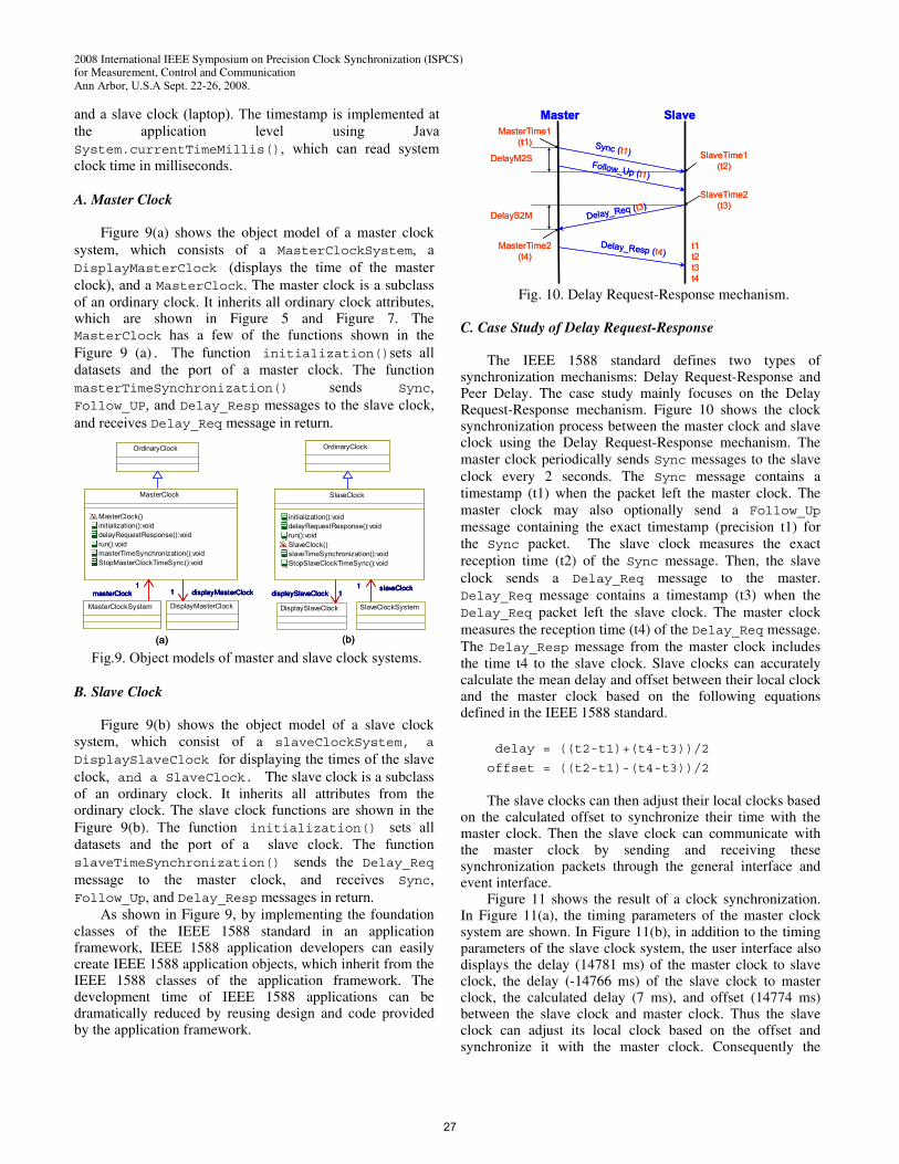
A. Master Clock
Figure 9(a) shows the object model of a master clock
system, which consists of a MasterClockSystem, a DisplayMasterClock (displays the time of the master clock), and a MasterClock. The master clock is a subclass of an ordinary clock. It inherits all ordinary clock attributes, which are shown in Figure 5 and Figure 7. The MasterClock has a few of the functions shown in the Figure 9 (a). The function initialization()sets all datasets and the port of a master clock. The function masterTimeSynchronization() sends Sync, Follow_UP, and Delay_Resp messages to the slave clock, and receives Delay_Req message in return.
OrdinaryClock
MasterClock
MasterClock()initialization():voiddelayRequestResponse():voidrun():voidmasterTimeSynchronization():voidStopMasterClockTimeSync():void
SlaveClock
initialization():voiddelayRequestResponse():voidrun():voidSlaveClock()slaveTimeSynchronization():voidStopSlaveClockTimeSync():void
OrdinaryClock
1masterClock
MasterClockSystem
1masterClock
SlaveClockSystem
1 slaveClock1 slaveClock
DisplayMasterClock
1 displayMasterClock1 displayMasterClock
DisplaySlaveClock
1displaySlaveClock 1displaySlaveClock
(a) (b)
OrdinaryClock
MasterClock
MasterClock()initialization():voiddelayRequestResponse():voidrun():voidmasterTimeSynchronization():voidStopMasterClockTimeSync():void
SlaveClock
initialization():voiddelayRequestResponse():voidrun():voidSlaveClock()slaveTimeSynchronization():voidStopSlaveClockTimeSync():void
OrdinaryClock
1masterClock
MasterClockSystem
1masterClock
SlaveClockSystem
1 slaveClock1 slaveClock
DisplayMasterClock
1 displayMasterClock1 displayMasterClock
DisplaySlaveClock
1displaySlaveClock 1displaySlaveClock
(a) (b) Fig.9. Object models of master and slave clock systems.
B. Slave Clock
Figure 9(b) shows the object model of a slave clock
system, which consist of a slaveClockSystem, a
DisplaySlaveClock for displaying the times of the slave clock, and a SlaveClock. The slave clock is a subclass of an ordinary clock. It inherits all attributes from the ordinary clock. The slave clock functions are shown in the Figure 9(b). The function initialization() sets all datasets and the port of a slave clock. The function slaveTimeSynchronization() sends the Delay_Req message to the master clock, and receives Sync, Follow_Up, and Delay_Resp messages in return.
As shown in Figure 9, by implementing the foundation classes of the IEEE 1588 standard in an application framework, IEEE 1588 application developers can easily create IEEE 1588 application objects, which inherit from the IEEE 1588 classes of the application framework. The development time of IEEE 1588 applications can be dramatically reduced by reusing design and code provided by the application framework.
Master SlaveMasterTime1
(t1)SlaveTime1
(t2)
MasterTime2(t4)
SlaveTime2(t3)
DelayM2S
DelayS2M
Sync (t1)Follow_Up (t1)
Delay_Resp (t4)
Delay_Req (t3)
t1t2t3t4
Master SlaveMasterTime1
(t1)SlaveTime1
(t2)
MasterTime2(t4)
SlaveTime2(t3)
DelayM2S
DelayS2M
Sync (t1)Follow_Up (t1)
Delay_Resp (t4)
Delay_Req (t3)
t1t2t3t4
Fig. 10. Delay Request-Response mechanism.
C. Case Study of Delay Request-Response
The IEEE 1588 standard defines two types of synchronization mechanisms: Delay Request-Response and Peer Delay. The case study mainly focuses on the Delay Request-Response mechanism. Figure 10 shows the clock synchronization process between the master clock and slave clock using the Delay Request-Response mechanism. The master clock periodically sends Sync messages to the slave clock every 2 seconds. The Sync message contains a timestamp (t1) when the packet left the master clock. The master clock may also optionally send a Follow_Up message containing the exact timestamp (precision t1) for the Sync packet. The slave clock measures the exact reception time (t2) of the Sync message. Then, the slave clock sends a Delay_Req message to the master. Delay_Req message contains a timestamp (t3) when the Delay_Req packet left the slave clock. The master clock measures the reception time (t4) of the Delay_Req message. The Delay_Resp message from the master clock includes the time t4 to the slave clock. Slave clocks can accurately calculate the mean delay and offset between their local clock and the master clock based on the following equations defined in the IEEE 1588 standard.
delay = ((t2-t1)+(t4-t3))/2
offset = ((t2-t1)-(t4-t3))/2 The slave clocks can then adjust their local clocks based
on the calculated offset to synchronize their time with the master clock. Then the slave clock can communicate with the master clock by sending and receiving these synchronization packets through the general interface and event interface.
Figure 11 shows the result of a clock synchronization. In Figure 11(a), the timing parameters of the master clock system are shown. In Figure 11(b), in addition to the timing parameters of the slave clock system, the user interface also displays the delay (14781 ms) of the master clock to slave clock, the delay (-14766 ms) of the slave clock to master clock, the calculated delay (7 ms), and offset (14774 ms) between the slave clock and master clock. Thus the slave clock can adjust its local clock based on the offset and synchronize it with the master clock. Consequently the
27
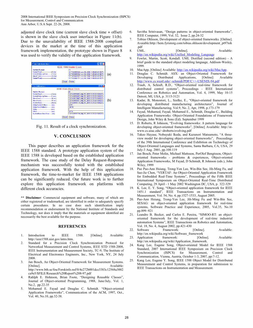
2008 International IEEE Symposium on Precision Clock Synchronization (ISPCS) for Measurement, Control and Communication Ann Arbor, U.S.A Sept. 22-26, 2008. adjusted slave clock time (current slave clock time + offset) is shown in the slave clock user interface in Figure 11(b). Due to the unavailability of IEEE 1588-2008 compliant devices in the market at the time of this application framework implementation, the prototype shown in Figure 8 was used to verify the validity of the application framework.
(a)
(b)
Fig. 11. Result of a clock synchronization.
V. CONCLUSION
This paper describes an application framework for the IEEE 1588 standard. A prototype application system of the IEEE 1588 is developed based on the established application framework. The case study of the Delay Request-Response mechanism was successfully tested with the established application framework. With the help of this application framework, the time-to-market for IEEE 1588 applications can be significantly reduced. Our future work is to further explore this application framework on platforms with different clock accuracies. ** Disclaimer: Commercial equipment and software, many of which are either registered or trademarked, are identified in order to adequately specify certain procedures. In no case does such identification imply recommendation or endorsement by the National Institute of Standards and Technology, nor does it imply that the materials or equipment identified are necessarily the best available for the purpose.
REFERENCES 1. Introduction to IEEE 1588. [Online]. Available:
http://ieee1588.nist.gov/intro.htm. 2. Standard for a Precision Clock Synchronization Protocol for
Networked Measurement and Control Systems, IEEE STD 1588-2008, IEEE Instrumentation and Measurement Society, TC-9, The Institute of Electrical and Electronics Engineers, Inc., New York, NY, 24 July 2008.
3. Jan Bosch, An Object-Oriented Framework for Measurement Systems. [Online]. Available: http://www.bth.se/fou/Forskinfo.nsf/0/4e272b001dce3383c12568a3002ca9e5/$FILE/Research%20Report%208-97.pdf
4. Rahlph E. Hohnson, Brian Foote, “Designing Reusable Classes”, Journal of Object-oriented Programming, 1988, June/July, Vol. 1, No.2, pp.22-35
5. Mohamed E. Fayad and Douglas C. Schmidt. “Object-oriented Application Frameworks”, Communication of the ACM, 1997, Oct., Vol. 40, No.10, pp.32-38.
6. Savitha Srinivasan, “Design patterns in object-oriented frameworks”, IEEE Computer, 1999, Vol. 32, Issue 2, pp.24-32
7. Tobias Ohlsson, Development of object-oriented frameworks. [Online]. Avaiable:http://hem.fyristorg.com/tobias.ohlsson/development_pt97toh.pdf
8. UML. [Online]. Available: http://en.wikipedia.org/wiki/Unified_Modeling_Language
9. Fowler, Martin, Scott, Kendall. UML Distilled (second edition) - A brief guide to the standard object modeling language, Addison-Wesley, 1999.
10. MacApp, [Online] Available: http://en.wikipedia.org/wiki/MacApp. 11. Douglas C. Schmidt. ASX: an Object-Oriented Framework for
Developing Distributed Applications, [Online]: Available http://www.cs.wustl.edu/~schmidt/PDF/C++-USENIX-94.pdf
12. Traub, A, Schraft, R.D., “Object-oriented real-time framework for distributed control systems”, Proceedings - IEEE International Conference on Robotics and Automation, Vol. 4, 1999, May 10-15 Detroit, MI, USA, p. 3115-3121
13. Kadar, B, Monostori, L., Szelke, E., “Object-oriented framework for developing distributed manufacturing architectures”, Journal of Intelligent Manufacturing, Vol.9, No. 2, Apr, 1998, p.173-179
14. Fayad, Mohamed, Fayad, Mohamed E., Schmidt, Douglas C., Building Application Frameworks: Object-Oriented Foundations of Framework Design, John Wiley & Sons (Ed). September 1999
15. D. Roberts, R Johnson, “Evolving frameworks: A pattern language for developing object-oriented frameworks”, [Online] Available: http://st-www.cs.uiuc.edu/~droberts/evolving.pdf
16. Takeo Hayase, Nobuyuki Ikeda, and Kazunori Matsumoto, “A three-view model for developing object-oriented frameworks”, Proceedings of the 39th International Conference and Exhibition on Technology of Object-Oriented Languages and Systems, Santa Barbara, CA, USA, 29 July-3 Aug. 2001, pp.108-119
17. Jan Bosch, Peter Molin, Michael Mattsson, PerOlof Bengtsson, Object-oriented frameworks - problems & experiences, Object-oriented Application Frameworks, M Fayad, D Schmidt, R Johnson (eds.), John Wiley, 1999
18. Pao Pao-Ann Hsiung, Trong-Yen Lee, Win-Bin See, Jih-Ming Fu, and Sao-Jie Chen, “VERTAF: An Object-Oriented Application Framework for Embedded Real-Time Systems”, Proceedings of the Fifth IEEE International Symposium on Object-Oriented Real-Time Distributed Computing, 29 April - 1 May 2002 Washington DC, USA, p. 322-329
19. K. Lee, E. Y. Song, “Object-oriented application framework for IEEE 1451.1 standard”, IEEE Transactions on Instrumentation and Measurement, Vol. 54, No. 4, pp.1527-1533, August 2005.
20. Pao-Ann Hsiung, Trong-Yen Lee, Jih-Ming Fu and Win-Bin See, SESAG: an object-oriented application framework for real-time systems, Software Practice and Experience, 2005, Vol.35, No.10 pp.899–921
21. Leandro B. Becker, and Carlos E. Pereira, “SIMOO-RT: an object-oriented framework for the development of real-time industrial automation Systems”, IEEE Transactions on Robotics and Automation, Vol. 18, No. 4, August 2002, pp.421-430
22. Software Framework: [Online]. Available: http://en.wikipedia.org/wiki/Software_framework
23. Application framework: [Online]. Available: http://en.wikipedia.org/wiki/Application_framework.
24. Kang Lee, Eugene Song, Object-oriented Model for IEEE 1588 Standard, 2007 International IEEE Symposium on Precision Clock Synchronization (ISPCS) for Measurement, Control and Communication, Vienna, Austria, October 1-3, 2007, pp:7-12.
25. Kang Lee, Eugene Y. Song, IEEE 1588 Object Model for Distributed Measurement and Control Systems, in preparation for submission to IEEE Transactions on Instrumentation and Measurement.
28