Embed Size (px)
Citation preview
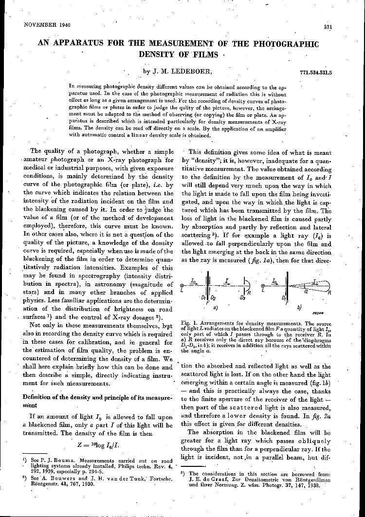
NOVEMBER 1940 331
AN APPARATUS FOR THE MEASUREMENT OF THE PHOTOGRAPHICDENSITY OF FILMS
by J. M. LEDEBOER,
In measuring photographic density different values can be obtained according to the ap-paratus used. In the case of the photographic measurement of radiation this is withouteffect as long as a given arrangement is used. For the recording of density curves of photo-graphic films or plates in order to judge the qality of the picture, however, the arrange-ment must be adapted to the method of observing (or copying) the film or plate. An ap-paratus is described which is intended particularly for density measurements of X-rayfilms. The density can be read off directlyon a scale. By the application of an amplifierwith automatic control a linear density scale is ohtained. .
The quality' of a photograph, whether a simple.amateur photograph or an X-ray photograph formedicalor industrial purposes, with given exposureconditions, is mainly determined by the density.curve of the photographic film (or plate), i.e. bythe curve which indicates the relation between theintensity 'of the radiation incident on the film andthe blackening caused by it. In order to 'Judge thevalue of a film (or of the method' of developmentemployed), therefore, this curve must b,e known.In other cases also, where it is not a question of thequality of the picture, a knowledge of the densitycurve is required, especially when use ismade oftheblackening of the film in order to determin~ quan-,titatively radiation intensities. Examples of thismay be found in spectrography (intensity distri-bution in spectra), in astronomy (magnitude ofstars) and in many other branches of appliedphysics. Less familiar applications are the determin-ation of' the distrihution of brightness on roadsurfaces 1) and the control of X-ray dosages 2).Not only in these measurements themselves, bVt
also in recording the density curve which is requiredin these cases for calibration, and in general forthe' estimation of film quality, the problem is en-countered of determining the density of a film. Weshall here explain-briefly how this can be done andthen describe à simple, directly indicating instru-ment for such measurements.
Definition of the density and principle of its measure-ment
If an amount of light 10 is allowed to fall upona blackened film, only a part I of this light will betransmitted. The density of the film is then
Z = 1010g 10/1.
1) See P. J. Bouma. Measurements carried out on roadlighting systems already installed, Philips techno Rev. 4, -292, 193~, especially p. 294-5.
2) See' A. Bouwers and J. H. van der 'I'uuk;' Fortscbr.Röntgenstr. 41, 767, 1930.
771.534.531.5
This definition gives some idea of what is meantby "density"; it is, however, inadequate for a quan-'tita'tive measurement. The value obtained accordingto the definition by the measurement of ID and, Iwill still depend very much upo~ the way in which, the light is made to fall upon thefilm being investi-gated, and upon the way in which .the light is cap-tured which has been transmitted by the film. Theloss of light in the blackened film is caused partlyby absorption and partly by reflection and lateralscattering 3). If for example a light ray (10) isallowed .to fall perpendicularly upon the film andthe light emerging at the back in the same directionas the ray is measured (fig. la), then for that direc-
a).1/J:149
Fig. 1. Arrangements for density measurements. The sourceof lightLradiates on theblackened filmF a quantity of light 10'only part of which I passes through to the receiver R. Ina) R receives only the direct ray because of the 'diaphragmsD1-D3, in b); it receives in addition all the rays scattered withinthe angle a.
. tion the absorbed and reflected light as well as thescattered light is lost. If on the other hand the lightemerging within a certain angle is measured (fig.lb)- and this is practically always the case, thanksto the finite aperture of the receiver of the light -then part of the sc at ter e d light is also measured,and therefore a lower density is found. In fig. 2athis effect is given for different densities. .
The absorption in the. blackened film will begreater for a light ray which passes obliquelythrough the filni than for a perpendicular ray. If thelight is incident, not .in a par~llel beam, but dif-
3) The considerations in this section are borrowed from:J. E. de Graaf, Zur Densitometrie von Röntgenfilmenund ihrer Normung. Z. wiss, Photogr. 37, 147, 1938.

332 PHILIPS TECHNICAL REVIEW Vol. 5, No. 11
fusely upon the film to he investigated, then, dueto this effect, a smaller value of 111.0' and thus ah igh er density, may be found with a greater aper-ture of the receiver, since in this case the raysincident upon the receiver pal's more 'obliquelythrough the film and are thus more attenuated.
oO!,--..,J,10=o--:20~o -3D,:! 0
-0:iJ)J6SS1
Fig. 2. Density value Z which is found in measuring the samefilm with receivers of different acceptance angles a (see fig. lb)according to de Graaf3). The four curves were obtainedwith four different heavily blackened films. a) A parallelbeam was incident on the film. b) The film was diffusely îl-luminated.
This is shown clearly in fig. 2b. For a quantitativeexplanation of the curves there shown the relationbetween absorption and ray direction as well as theeffect of scattering represented in fig. 2a must hetaken into account.Finally the colour of the light used for the
measurement and the spectral sensitivity of thereceiver will 'affect the value of 10 found, since thescattering by the grains of the blackened layerdepends upon the' wave length.If the purpose of the density ,measurement is
the determination of radiation intensities, it is oflittle importance what colour of light or directionof beam onc uses, if the density measurement iscarried ou,tin the same way in calibration and in themeasurement itself. The density is in this case onlyan intermediate quantity. If the density measure-ment is for the purpose ~f judging the photographic.quality of a film or plate, however, it inust be~ept in mind that the density differences are thecomponent element of the picture to be obtained,and thus that the manner in which the eye (or thecopying material) registers the density also playsa part in the quality which may be assigned to thepicture. In this case it is necessary to adapt thedensity measurement' to the manner of observationof the picture (or to the method of copying).The apparatus which we shall describe in the
following was especially developed for the measure-ment ofthe densityof X-ray films. X-ray filmsare usually examined by transmitted light with thehelp of a light box, i.e. with diffuse illumination.The eye of the observer is at a distance of about
'.
30 cm from the film. The diameter of the opening, of the "receiver", i;e. the diamter of the pupil ofthe eye, is about 1/2 cm. We have therefore chosenéxactly the same dimensions for our apparatus(fig. 3). As .receiver a photocell was used. The spec-tral sensitivity of this cell should actually hematched to the spectral eye sensitivity; in our 'case,however, this was unnecessary, since according to aproposal of de Graaf3) .we used the practicallymonochromatic light of a sodium lamp for themeasurements. For the observation of X-ray filmswith the light box the use of sodium light is notyet generally customary, it is, however, to be recom-mended in connection with the relatively slightfatique experienced by the eye upon long continuedobservation with sodium light.
300
Fig. 3. Arrangement for density measurement of X-ray films,adapted to the method by which the films are examined withthe light box. N sodium lamp, M frosted glass,Dl diaphragm,F film. The aperture of the photocell R is reduced by meansof the diaphragm, D2 to the diameter of the pupil of the eye(5 mm), the distance F-D2 is equal to the ordinary distancebetween eye and film (300 mm).
Construction of the apparatus.Arrangement fOT direct indication
The sodium lamp used in the apparatus burns onalternating current (50 cis), so that, a light fluxis obtained which alternates at 100 cis. Thephotocell serving as receiver for I therefore givesan alternating current of the same frequency. Thisis amplified in a two-stage A.C. amplifier, and afterrectification the output signal is measured with anordinary voltmeter (see the diagram of fig. 4).'The meter can he calibrated directly in densityvalues when care is taken that the extremities ofthe- scale always correspond to the value Z = °and Z = 00, respectively. For Z = 00, I = '0,and this is therefore the pointer indication with noinput signal. The pointer can be set accuratelyonthe line for 00 of the scale by means of a settingscrew on the meter. For'Z = 0, i;e. I = 10' thepointer, which here has its greatest deviation (it isbest to have it move from right to left) mustcoincide with the zero line of the scale. This is ac-complished with the help .of a variable, shunt(B in fig. 4) across the meter. The adjustment is only

· - 2J.'~-:---. -.
,I
NOVEMBER' 194,0 THE MEASUREMENT OF ,THE PHOTOGRAPHIC DENSITY OF FILMS
If an ordinary amplifier with a linear amplificationwere used, the meter deviation would be prop or-'tional to I,' i.e. we would obtain' a logarithmicscale for the density: 90 per cent of the availablescale length would be occupied by the region Z = 0to Z = 1, the following ~per cent by the regionZ = 1 to Z = 2, and the last one per cent by thevalues of Z greater thanZ. This is very undesirable,not only for radiation measurements, where ',the Calibration of the scale.same degree of accuracy throughout' the whole By adjustment of the potentiometer D mentioned,measuring region is desired, but also for judging the form of the control characteristic can be sothe quality of the picture, because the impressions influenced that the desired measuring region fallsproduced on the eye, according to the law of in a favourable position. Since in the case of X-rayWeber and Fecher, are approximately propor- films the region between Z = 0 ~nd Z = 2 is of'tional to the density. 'speci~l importance, it was desirable in the case
In order to obtain a density scale which is ap- of the apparatus in' question that the point Z = 1proximately linear in the region of densities which should stand in the middle of the scale. This was 'is of practical importance, an amplifier woul~ be accomplished in a very simple way. The signalneeded which amplifies less with a large input signal caused by 10 at the input of the amplifier was(I) than with a small input signal. This requirement replaced by a calibration voltage (applied 'at Arecalls the automatic volume control which is in fig. 4) which causes the same meter indicationemployed in radio receiving, sets; and .indeed the, (Z = 0). This voltage was .then lowered by a factorproblem can here be solved in an entirely anal- ,10. Since the current of the photocell is exactlyogous man~er 4). As first amplifier v~lve ,;e ~se, 'proportional to the light flux at the illuminationa variable mu pentode EF 9; the negative grid bIas, .intensities here prevailing, the attenuation of theof this valve is influenced 'by the rectified output calibration voltage by a factor 10 is exactly equiva-voltage of the amplifier, so that the operating point lent to the attenuation 'of the light flux by a filmon the valve characteristic is shifted to sections with the density Z = 1. By adjustment of D it waswith steeper slope, as the input signal becomes. now brought about that the pointer ofthe measuringsmaller. The "control" characteristic, i.e. the instrument coincided with the desired scale linerelation obtained between output and input signal, in the middle of the scale (fig. 5 full line curve).still depends upon the fraction of the output voltage In a similar way, namely by successively lowering(adjustable withpotentiometer D in fig.,4) fed back the calibration voltage by known factors, the rest
of the scale was then calibrated. In fig. 6 it maybe seen that the scale is fairly approximately linear
valid of course for a given value of the light flux 10'and this must be kept constant during the measure-ment (see below).
J6.JS2
Fig. 4. Connections of the density meter. R photocell; V two-stage amplifier containing a variable mu pentode EF 9 and anoutput pentode. M voltmeter indicating directly the density,with shunt B. D potentiometer for regulating the fractionof the output voltage fed back to the valve EF 9. A calibrationvoltage can be applied at A.. . "
The methodof obtaininga linear density scale
4) See C.W. Miller, A' linear photoelectric densitometer,Rev. sci, instrum. 6, 125, 1935.
to the input, but in the case of the valve EF 9it always has an approximately logarithmic section,with which a linear density scale can be obtainedin th~ desired rcgion (fig. 5):
Vuit100%
36JSS
80,- I.-.-
VIr:J.---- V I
1/ I I,- I
/' h/ II
,-I I.-'- 1/ I'" /
'" "/,- ~ ......- .-,. --,.,." _--_
- - -
60
40
20
o w m%~0,1s~3----------~2----------~1r-~-------no,
Fig. 5. Control characteristic (output voltage as a functionof the input voltage, both in per cen~of the val~e at I = Io) fordifferent adjustments of the porentiometer D In fig. 4.a) No control; linear ?haract?risti?, very unfavourable scale.b) Weak control (lossIn amplification, ~ factor 4); fo~Q<?,<l
the characteristic is already approximately Iogarithmic..c) Control as used by us (loss in amplification, a.factor 20);
the characteristic is about logarithmic for 0<Z<2.d) Very strong control. While the densi~y scale. here~y ob-
tained is linear up to Z = 3, the loss In amplification be-comes undesirably great.
333

334, PHILIPS TECHNICAL REVIEW Vol. 5, No. 11
up to about Z = 2. The calibration was controlledby attenuating the light falling upon the photocellby known amounts, by changing the distance of thelight source. The "density" measured alwaysshowed excellent agreement with the attenuationcalculated from the inverse square law.
Fig. 6. Density scale of the apparatus with a linear scale below.It may be seen that the density scale is approximately linearin the region between Z = 0 and Z = 2, which is the mostimportant for Xvray films. The ends Z = 0 and Z = 00 ofthe scale must be checked before the beginning of every meas-urement and readjusted if necessary. The mechanical restingposition of the pointer is on the extreme right, slightly beyonclthe point Z = 00.
Several details of the construction
In .fig. 7 a photograph is given of the completeapparatus. In the horizontal box is the sodium lampwith the accompanying supply transformer. Thesupply voltage is stabilized. Since the light fluxof the sodium lamp varies only very little withvariations in the supply voltage, the light flux 10is practically entirely independent of mains voltagefluctuations. The lamp is cooled by a slight aïrcurrent, since otherwise the outer bulh mightbecome too hot.The lamp illuminates a frosted glassplate (seefig.3)
which in turn serves as secondary light sourcefor the diffuse illumination of the film being exam-ined. The light passes through a diaphragm in thesmoothly-finished upper surface of the box intoa vertical tube blackened on the inside (fig. 7),and falls upon the photocell used as receiver. Whenthe film is slid over the smooth plate so that thelight falls upon the desired spot, the lower sectionof the tube is pulled down until it touches the film,so that the path of the light ray is entirely shieldedfrom stray light. The diaphragm in the plate hasa diameter of 5 mm and therefore the average-density of a circle of that diameter is measured.
If desired a smaller diaphragm can also be used,The amplifier and the accompanying supply
apparatus are housed in the vertical box. The supplyvoltage for the amplifier and the photocell is alsostabilized, so that the calibration of the densityscale is quite independent of fluctuations of themains voltage.
The operation of the apparatus is limited to thecontrol and if necessary to the readjustment of thetwo extremities of the scale before the beginning ofeach measurement. For setting the point Z = 0with the shunt across the measuring instrumerrt (Bin fig. 4, the corresponding knob may be seen aboveon the left in fig.7); one must of course wait untilthe light flux of the sodium lamp has reached itsfinal value, which is the case about 15 minutes afterswitching on. The potentiometer D for choosingthe correct control characteristic is not accessiblefrom the outside; its adjustment needs only seldomto be verified, namely when the variable mu valveis exchanged.
Fig. 7. Photograph of the apparatus. The sodium lamp is inthe horizontal box, on the smooth upper surface of this boxthe film being examined is placecl. The light shines throughthe film into the vertical tube at whose upper end in thehorizontal tube the photocell is mounted. The amplifier andthe accompanying supply apparatus are housed in the up-right box.
![Construction of an apparatus for the measurement …[Enter report no.] Construction of an apparatus for the measurement of current induced in a long conductor by local and distant](https://img.pdfslide.us/doc/110x75/5f6d990417c38d21b80ba12d/construction-of-an-apparatus-for-the-measurement-enter-report-no-construction.jpg)