Embed Size (px)
DESCRIPTION
http://www.seipub.org/ijace/paperInfo.aspx?ID=4568 The main purpose of this work is the development of an intelligent anti-skid braking system for business jet that would allow the maintenance of good performance during braking in all types of track conditions. In fact, one of the main problems in abs controllers modelling is due to the significantly variation of the optimal value of the friction coefficient closely related to the track conditions (dry, wet, icy); so it is extremely difficult to define a controller that ensures optimal braking performance in all environmental conditions. This study has involved the design of two controllers, based on computational intelligence techniques such as Artificial Neural Networks and Fuzzy Logic. In fact, AI is an excellent tool for the development of procedures dedicated to control systems which are complex and nonlinear like abs controllers. The application of these techniques seems particularly appropriate in the case of inadequate ph
Citation preview
International Journal of Automation and Control Engineering Volume 2 Issue 3, August 2013 www.seipub.org/ijace
101
An Anti-Skid Controller for Aircraft Applications Based on Computational Intelligence L. Barelli1, G. Bidini2, F. Bonucci*3
Department of Industrial Engineering, University of Perugia, Via G. Duranti 1/A4, Perugia 06125, Italy [email protected], [email protected], *[email protected] Abstract
The main purpose of this work is the development of an intelligent anti-skid braking system for business jet that would allow the maintenance of good performance during braking in all types of track conditions. In fact, one of the main problems in abs controllers modelling is due to the significantly variation of the optimal value of the friction coefficient closely related to the track conditions (dry, wet, icy); so it is extremely difficult to define a controller that ensures optimal braking performance in all environmental conditions.
This study has involved the design of two controllers, based on computational intelligence techniques such as Artificial Neural Networks and Fuzzy Logic. In fact, AI is an excellent tool for the development of procedures dedicated to control systems which are complex and nonlinear like abs controllers. The application of these techniques seems particularly appropriate in the case of inadequate physical models as in the case of friction between wheels and track. The developed controllers make possible to operate in an unstable equilibrium point in order to achieve optimum braking performance.
Keywords
Anti-Skid Control; Neural Networks; Fuzzy Logic
Introduction
The present work copes with the development of an anti-skid braking system dedicated to modern business jets equipped with electromechanical brakes. The braking system is a central component for the aircraft landing and realizes the largest part of the deceleration process dissipating most of its kinetic energy. So, it is important to optimize such a system in order to reduce the deceleration space and time, as well as to avoid wheels lock. Since 1940, different control systems have been designed and produced to prevent wheel slip during braking. The on-off controllers, the simplest used, generally consists of three components: the locking sensor, the control unit
and the solenoid valve (Bill K. et al., 2008); which are not able to modulate braking torque as a function of the slip but only to release the clamp in case of locked wheels. Instead, more innovative systems are able to generate a wide range of pressure modulations, depending on the wheels speed and its time derivative.
Such a typology of anti-skid systems results particularly useful because of the ability to support the pilot in the landing phase realizing the automatic modulation of the braking action to prevent the wheel blockage. This device, based on microprocessor technology, conventionally named Brake Management System (BMS) must be able to automatically determine the instantaneous best operational conditions of the brakes according to the information acquired by the on board sensors, such as the wheel angular velocity, the plane speed, the track conditions, beyond that the command of the pilot. An optimal anti-skid controller should regulate the brake torque to bring the slip factor (λ), calculated on the basis of both wheel and aircraft speeds, to the value which maximizes the tire-asphalt friction coefficient. Therefore, the improvement of BMS system performance, under varying track conditions, is a complex nonlinear problem. In literature, many studies concern the development of closed-loop models for anti-skid systems, especially for automotive applications (Harifi A. et al. 2008, Wu M. et al. 2003, Matusko J. et al. 2008). A non-linear model-based brake controller was presented in (Mirzaeinejad H. et al., 2010), where a specific control law has been developed by minimizing the difference between predicted and desired responses of the wheel slip. Instead in (Gualdi S. et al., 2008) a closed-loop controller was employed to model the anti-skid behavior in a multibody code, developed to analyze the aircraft landing gear instability. In this case, the adopted braking strategy achieves an optimal slip ratio chosen in order to maximize the tire-ground friction coefficient, even if only for dry conditions. In fact, a
www.seipub.org/ijace International Journal of Automation and Control Engineering Volume 2 Issue 3, August 2013
102
value of 0.3, which corresponds to the maximum friction coefficient for smooth dry asphalt, is considered.
Moreover, also computational intelligence (CI) techniques are applied in this sector, allowing the achievement of high performance in anti-skid controls (Matusko J. et al. 2008, Layne J.R. et al. 1993, Ursu I. et al. 2003). The use of CI, in fact, is particularly appropriate in absence of adequate physical models, as in the case under study, relative to the complex friction phenomenon between wheel and track (Layne j.R. et al. 1993, Mauer G.F., 1995). In the following, some details related to CI techniques applications are reported.
In (Poursamad A., 2009) an adaptive anti-skid, based on a linear feedback controller and two feedforward neural networks, is presented and the system is capable to estimate the nonlinearities associated to the braking phenomena under various road conditions. A one-wheel friction model for cars tire-road force estimation, including a neural network employed to maximize the force estimation accuracy, has also been presented in (Matusko J. et al., 2008). Furthermore, the maintenance of sliding regime during braking has been investigated in (Topalov A.V. et al., 2011), where the antilock braking system is under a closed-loop with a conventional PD controller and an adaptive neuro-fuzzy controller.
In (Somakumar R. et al., 1999) an intelligent anti-skid controller for a tricycle undercarriage airplane was presented, based on artificial neural networks, to generate a braking correction factor receiving as inputs the plane velocity, the wheel angular velocity, the plane deceleration and the asphalt conditions. Finally, (Ursu I. et al.,2003) proposed a fuzzy controller for a military jet based on detection of the slip factor and this target was achieved through the development of road label inferring diagram that ensured the avoiding of wheel’s blockage, even in the worst road conditions and in case of additive measurement noise. The controller, at each decision step, employs three input variables for each braked wheel: wheel slip, predicted wheel slip and a threshold control variable.
The present study concerns the development of anti-skid controllers for business jets, generally characterized by two braked rear landing gears, as a particular application not investigated in the studies cited above. The authors chose to apply CI techniques, in analogy of (Somakumar R. et al. 1999, Ursu I. et al. 2003), because it is particularly suitable for the solution of non-linear and complex problems; moreover, such
techniques generally allow real-time calculation thanks to their short computation time.
The target of the present study is the development of two modulating anti-skids, by applying Artificial Neural Networks and Fuzzy Logic respectively, aiming to:
- obtain friction coefficient maximization, in function of the asphalt conditions, by means of a simple and robust control loop;
- avoid the problem concerning uncertainty of the variables involved in the phenomenon, such as the wheel-asphalt adhesion condition;
- extrapolate a relationship between the physical parameters of the plane and the braking correction coefficient;
- anti-skids computational time coherent with the characteristic time of the braking phase up to the airplane arrest.
Moreover, with respect to technical literature, two further specific targets were identified and then reached. Specifically, the developed anti-skid, with particular attention to the neural one, is characterized by:
- reduction to only two input parameters (plane deceleration and slip factor) and relative sensors needed by the BMS;
- design of an auto-adaptive anti-skid in relation to the asphalt conditions.
The developed anti-skid systems, as detailed in the follow, can ensure optimal braking performance, in terms of friction coefficients, in all environmental conditions (such as dry, wet and icy asphalt), showing a considerable reduction of stopping time and spaces with respect to on-off anti-skid solution.
In the first part of the present study, the mathematical modeling of braking phenomenon, defining aircraft physical variables and ground-tire interaction, has been presented. At the start, a model of the aircraft was implemented taking into consideration the forces exchanged with the ground during landing. Ground-tire interaction was modeled using the Pacejka model (Poursamad A. 2009, Topalov A.V. et al. 2011, Somakumar R. et al. 1999, Ursu I. et al. 2003, Drakunov S. et al. 1994), which was provided in graphical form, for different road grip conditions, a relationship between friction coefficient and slip factor representative of the tire slip. Subsequently to designing the anti-skid control loop, the two anti-skid controllers were developed and then implemented in

International Journal of Automation and Control Engineering Volume 2 Issue 3, August 2013 www.seipub.org/ijace
103
the control-loop. The last part of the work was focused on the calibration and application to a particular business jet of the developed controllers.
Finally, system performance was verified by the implementation of numerous simulations varying the operating conditions of the aircraft and its mass from minimum to maximum allowable take-off value. Moreover, the comparison with other solutions was executed in order to highlight the main differences of the developed anti-skids, such as adaptability to external conditions change and rapid response.
System Model
Landing is the phase of flight where a plane makes contact with the ground. Landing speed depends on plane typologies: a business jet approaches the land with an average speed of about 140-130 knots (48-54 knots for small single engine aircrafts).
The reference standards divide the landing space into three distinct segments (Milde M., 2008): the approaching phase, the rotation distance (within which the airplane, with the main undercarriage already on the ground, leads to landing also the front undercarriage) and, finally, the deceleration of the aircraft on the track. In this study, only the third phase was taken into consideration, assuming that the entire kinetic rate was dissipated by the brake system. Below models of aircraft, wheel and tire-asphalt interaction have been described.
Aircraft Model
The bi-dimensional model was set, determining the balance of forces acting on the aircraft, in order to estimate the load on wheels and to study the dynamics of wheels when subjected to braking. The motion dynamics, arising from the rotation of the vehicle about the vertical axis, was not considered; moreover as well lateral tire forces and pitch and roll effects were neglected (Ursu I. et al, 2003). Relative to wheels, frictional force between front wheel and runway was not taken into account because negligible (Somakumar R. et al., 1999). Further, an aircraft model with lumped masses over a single wheel was adopted (yadav D. et al., 1995); therefore, uneven braking forces applied on wheels were not considered. Finally, the flexibility of the landing gears was not taken into account.
Therefore, the two main equations of static, referring to balance of external forces (active and reactive) and resulting momentum (respect to the barycenter), were set in consideration of weight force and ground
reaction forces respectively applied to center of gravity and contact point of each wheel (eq. 1):
(1)
To maximize the horizontal component of frictional forces directly proportional to the load, it is usual to increase load by bringing the rear main landing undercarriage near the plane center of gravity and the trajectory of the plane is still guaranteed by the rear wheels through a differential brake drive between the two wheels.
FIG. 1 FORCES ACTING IN STATIC CONDITIONS
Wheel modeling (Figure 2) requires the knowledge of its characteristic measures (such as inertia and radius) and the determination of forces and momenta acting on it, such as:
weight force P= (M+m)g, which also includes the percentage of weight that the aircraft carries on;
binding reaction F = (Fx, Fn) that the ground practices on the wheel;
braking torque T exerted by the brake.
From the balance of these forces with inertial ones, the first and the second cardinal equation of mechanics (2) can be written:
(2)
with:
M: rate of aircraft weight load on the wheel, obtained by dividing the reaction by the acceleration of gravity: M = Rp / g;
m: I:
GH:
wheel mass (negligible respect to M); wheel momentum of inertia; distance between center and ground contact point.
In (3), vertical and horizontal projections of the first equation of (4) are reported, together with the second one referred to the wheel rotational axe:
(3)
www.seipub.org/ijace International Journal of Automation and Control Engineering Volume 2 Issue 3, August 2013
104
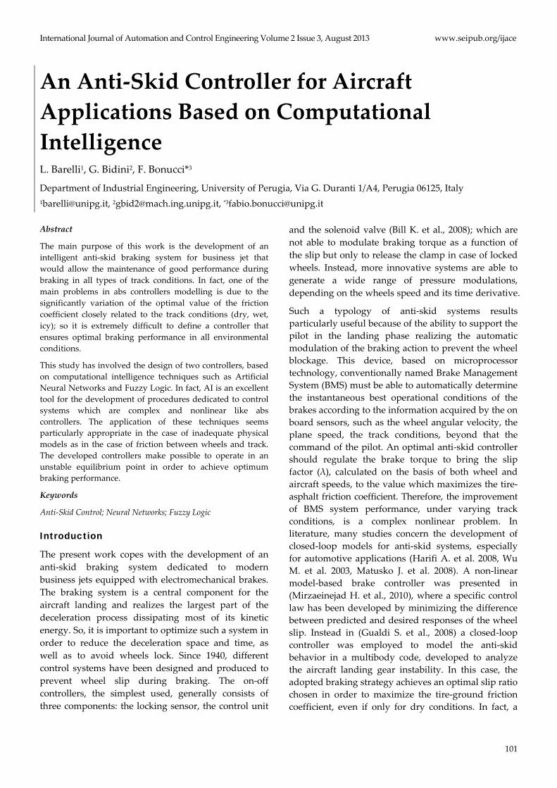
Knowing that Φx = μΦn, where μ is the friction
coefficient, the .
V e.ω expressions can be obtained (4)
as follows:
(4)
FIG. 2 FORCES ACTING ON THE WHEEL
Therefore, wheel model is characterized by two degrees of freedom and requires two parameters to describe the dynamics, because the two accelerations are each other independent. Integrating these values, both aircraft and wheel speeds, which permit to evaluate the slip factor λ, can be determined. Such a parameter, defined according to equation (5), denotes the tendency to slip of the undercarriage wheels and zero slip indicates rolling without sliding, while values of the slip factor close to 1 indicate locked wheel.
(5)
Ground-Tire Interaction Model
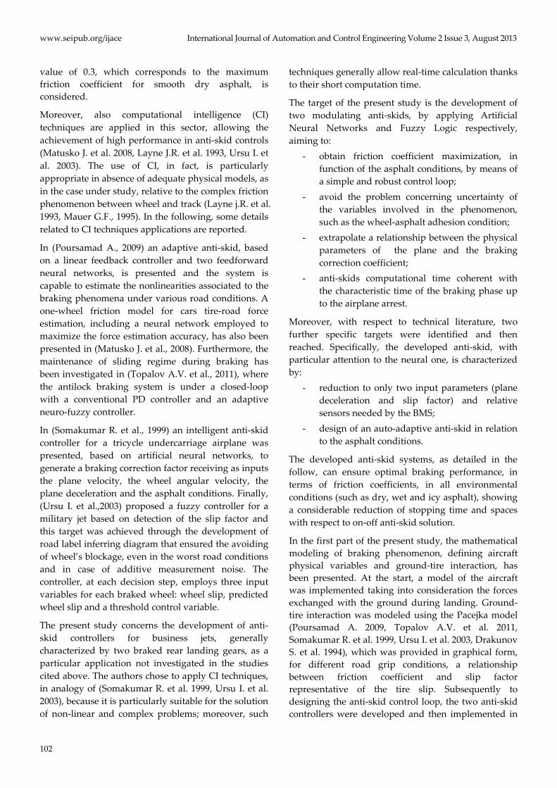
Ground-tire interaction permits to develop a friction model to be applied in the anti-skid controller. In general, friction coefficient μ depends on slip factor λ, reaction Φn, aircraft's speed V and track conditions (dry, wet or snowy/icy), as well as on secondary factors such as size and shape of the tread, tire pressure and profile of the track. The most common model used in literature is the Pacejka (Poursamad A. 2009, Topalov A.V. et al. 2011, Somakumar R. et al. 1999, Ursu I. et al. 2003, Drakunov S. et al. 1994), which uses static maps to provide relationship between μ and λ. In fact, the model assumes that if all other parameters are fixed, μ is a function only of the slip factor, μ=μ(λ), and this function admits a single maximum. This can be noted from the experimental curves μ=μ(λ) of Figure 3, valid for conditions of snow, dry and wet asphalt; in particular friction coefficient degrades along the whole curve with a maximum of about 0.1 and 0.4 for respectively snow and wet conditions. In addition, this maximum also moves to the left from asphalt dry condition to the snow case; i.e.
the skid engages for lower values of the slip factor. Target of the anti-skid development is, therefore, to maintain for all track conditions the level of slip at values that maximize adherence.
FIG. 3 SLIP FACTOR VS FRICTION COEFFICIENT
Anti-Skids and Control Loop Development
This section describes the methodology adopted for anti-skids development. In particular, the application of Artificial Neural Networks (ANNs) and Fuzzy Logic (FL) are presented in Sections 2.1 and 2.2 respectively. Before, as well a description of the other sub-systems, part of the complete control loop, is provided. The control loop, including anti-skid, constitutes a simulator of a certain business jet (according to the parameters set) when equipped with the developed brake controllers.
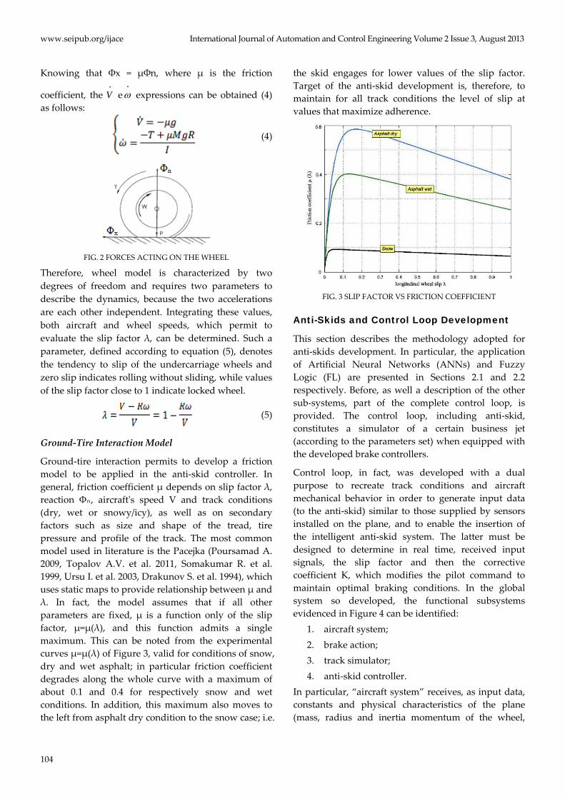
Control loop, in fact, was developed with a dual purpose to recreate track conditions and aircraft mechanical behavior in order to generate input data (to the anti-skid) similar to those supplied by sensors installed on the plane, and to enable the insertion of the intelligent anti-skid system. The latter must be designed to determine in real time, received input signals, the slip factor and then the corrective coefficient K, which modifies the pilot command to maintain optimal braking conditions. In the global system so developed, the functional subsystems evidenced in Figure 4 can be identified:
1. aircraft system; 2. brake action; 3. track simulator; 4. anti-skid controller.
In particular, “aircraft system” receives, as input data, constants and physical characteristics of the plane (mass, radius and inertia momentum of the wheel,
International Journal of Automation and Control Engineering Volume 2 Issue 3, August 2013 www.seipub.org/ijace
105
gravity acceleration, undercarriage distance from aircraft center of gravity) and the current values of friction coefficient μ and braking torque T; as outputs it provides to the anti-skid, through implementation of the model presented in Section 2.1, the slip factor (sent as feed-back also to the “track simulator”) and the aircraft deceleration. Therefore the subsystem provides indirectly also wheels speed.
FIG. 4 (a) BLOCK DIAGRAM AND (b) SIMULINK DIAGRAM OF
THE CONTROL RIG BOTH REFERRED TO THE CASE OF NEURAL ANTI-SKID (ONLY 2 PARAMETERS PROVIDED IN
INPUTS)
To value the performances of developed anti-skid controllers in the worst operating conditions, a braking torque step (“brake action”) was considered (no transfer functions of the brake system are included in the system), producing the instantaneous switch from zero to the maximum value that the brake can generate.
Track simulation, instead, needs to determine the instantaneous friction coefficient through suitable interpolation based on the Pacejka experimental curves (Matusko J. et al., 2008). This coefficient is only function of the slip factor determined by the “aircraft system” and of the track conditions. The discretization process of each curve has involved 101 points, in order to have a value of the friction coefficient for each percentage point of the slip factor. The instantaneous friction coefficient, so evaluated, was sent again in input to the “aircraft system”.
The whole system was implemented in Matlab® Simulink environment.
Neural Anti-Skid
This anti-skid, developed through application of ANNs, consists of two functional subsystems: an
artificial neural network and a torque modulator.
A neural network anti-skid represents a "smart" instrument capable to make a continuous modulation, unlike the on-off systems, and generate data in real-time with a computation time compatible with the brake phenomenon characteristic time. Unlike systems already available, the developed anti-skid self-recognizes grip conditions on the basis of measured input data and, consequently, generates the output without any further manual setting of the pilot. Therefore, as input variables of the network, slip factor and aircraft acceleration, which is directly proportional to the friction coefficient, were selected. Braking corrective coefficient K (variable in the range 0-1), instead, was chosen as the output parameter.
1) Training Data Set
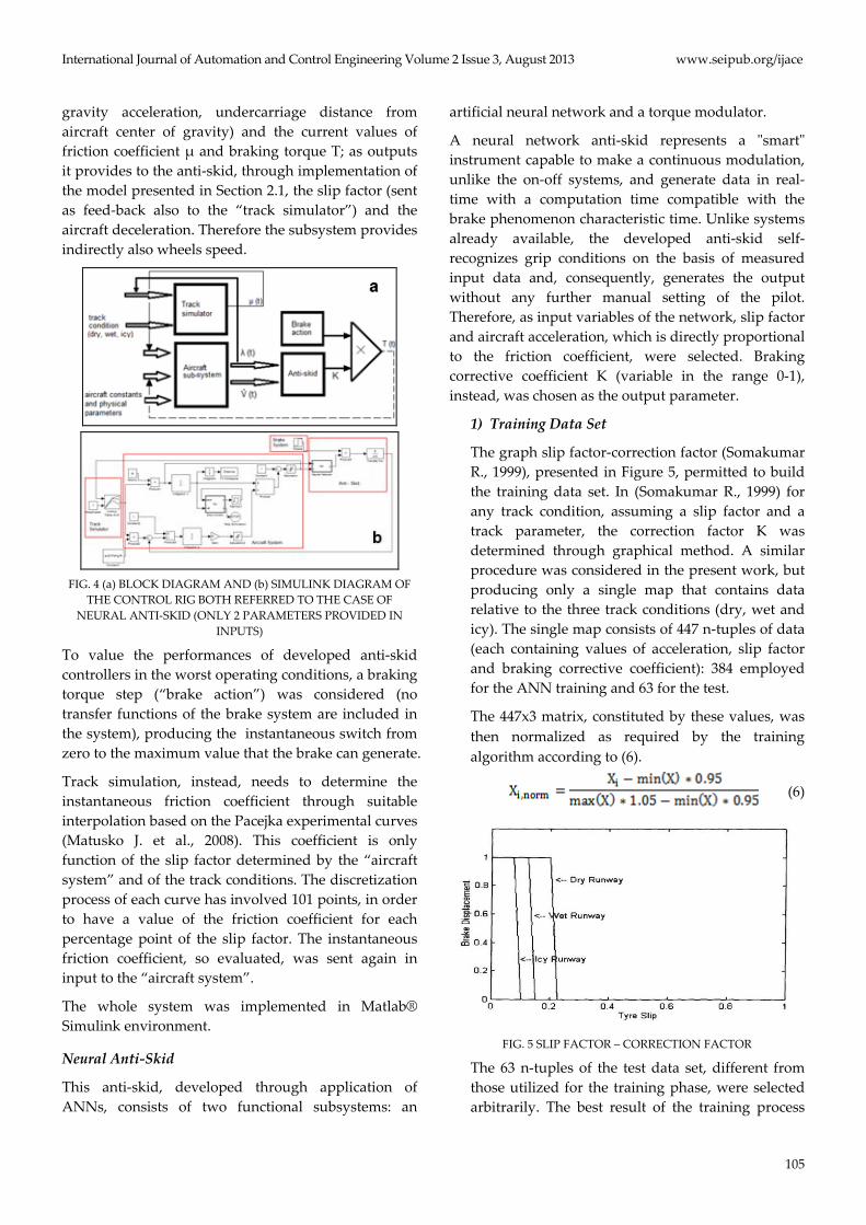
The graph slip factor-correction factor (Somakumar R., 1999), presented in Figure 5, permitted to build the training data set. In (Somakumar R., 1999) for any track condition, assuming a slip factor and a track parameter, the correction factor K was determined through graphical method. A similar procedure was considered in the present work, but producing only a single map that contains data relative to the three track conditions (dry, wet and icy). The single map consists of 447 n-tuples of data (each containing values of acceleration, slip factor and braking corrective coefficient): 384 employed for the ANN training and 63 for the test.
The 447x3 matrix, constituted by these values, was then normalized as required by the training algorithm according to (6).
(6)
FIG. 5 SLIP FACTOR – CORRECTION FACTOR
The 63 n-tuples of the test data set, different from those utilized for the training phase, were selected arbitrarily. The best result of the training process
www.seipub.org/ijace International Journal of Automation and Control Engineering Volume 2 Issue 3, August 2013
106
was obtained with a configuration of 40 neurons in the first layer and 30 neurons in the second, with a RMS (7) error about 2% reached in the test phase.
(7)
Fuzzy Logic Anti-Skid
To model the fuzzy logic controller, a further input to the anti-skid was considered with respect to the previous case and the diagram of Figure 4a. In fact, slip factor, aircraft deceleration and track conditions (in terms of dry, wet or icy according to the pilot selection) were identified as input parameters. In analogy to the case of neural anti-skid, the correction factor K was chosen as output.
1) Inputs and Output Modeling
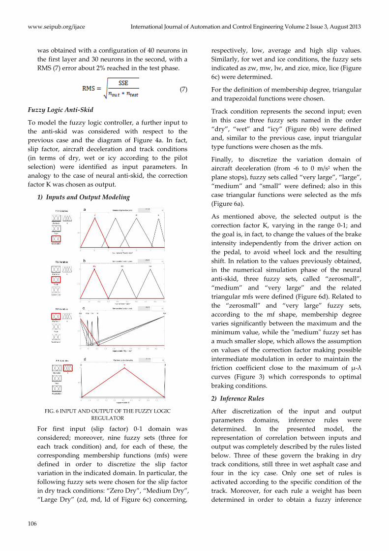
FIG. 6 INPUT AND OUTPUT OF THE FUZZY LOGIC
REGULATOR
For first input (slip factor) 0-1 domain was considered; moreover, nine fuzzy sets (three for each track condition) and, for each of these, the corresponding membership functions (mfs) were defined in order to discretize the slip factor variation in the indicated domain. In particular, the following fuzzy sets were chosen for the slip factor in dry track conditions: “Zero Dry”, “Medium Dry”, “Large Dry” (zd, md, ld of Figure 6c) concerning,
respectively, low, average and high slip values. Similarly, for wet and ice conditions, the fuzzy sets indicated as zw, mw, lw, and zice, mice, lice (Figure 6c) were determined.
For the definition of membership degree, triangular and trapezoidal functions were chosen.
Track condition represents the second input; even in this case three fuzzy sets named in the order “dry”, “wet” and “icy” (Figure 6b) were defined and, similar to the previous case, input triangular type functions were chosen as the mfs.
Finally, to discretize the variation domain of aircraft deceleration (from -6 to 0 m/s2 when the plane stops), fuzzy sets called “very large”, “large”, “medium” and “small” were defined; also in this case triangular functions were selected as the mfs (Figure 6a).
As mentioned above, the selected output is the correction factor K, varying in the range 0-1; and the goal is, in fact, to change the values of the brake intensity independently from the driver action on the pedal, to avoid wheel lock and the resulting shift. In relation to the values previously obtained, in the numerical simulation phase of the neural anti-skid, three fuzzy sets, called “zerosmall”, “medium” and “very large” and the related triangular mfs were defined (Figure 6d). Related to the “zerosmall” and “very large” fuzzy sets, according to the mf shape, membership degree varies significantly between the maximum and the minimum value, while the "medium" fuzzy set has a much smaller slope, which allows the assumption on values of the correction factor making possible intermediate modulation in order to maintain the friction coefficient close to the maximum of μ-λ curves (Figure 3) which corresponds to optimal braking conditions.
2) Inference Rules
After discretization of the input and output parameters domains, inference rules were determined. In the presented model, the representation of correlation between inputs and output was completely described by the rules listed below. Three of these govern the braking in dry track conditions, still three in wet asphalt case and four in the icy case. Only one set of rules is activated according to the specific condition of the track. Moreover, for each rule a weight has been determined in order to obtain a fuzzy inference

International Journal of Automation and Control Engineering Volume 2 Issue 3, August 2013 www.seipub.org/ijace
107
system that produces, as much as possible, the braking performance achieved by the neural controller.
In the following the rules set: 1. If slip is zd and asphalt is dry and
deceleration is not s then k is vl 2. If slip is m and asphalt is dry and
deceleration is vl then k is m 3. If slip is l and asphalt is dry and
deceleration is not vl then k is zs 4. If slip is zw and asphalt is wet and
deceleration is not vl then k is vl 5. If slip is mw and asphalt is wet and
deceleration is not l then k is m 6. If slip is lw and asphalt is wet and
deceleration is not vl then k is zs 7. If slip is zice and asphalt is ice and
deceleration is not m then k is vl 8. If slip is mice and asphalt is ice and
deceleration is m then k is m 9. If slip is lice and asphalt is ice and
deceleration is not m then k is zs 10. If slip is zice and asphalt is ice and
deceleration is not s then k is vl
As de-fuzzification process used to determine output exact value, the centroid method was applied. The fuzzy controller so developed was inserted in the control loop ring; the produced output was then multiplied by the braking torque generated by the brake subsystem, thereby obtaining directly the modulated torque (without torque modulator od Figure 4b).
Simulation Results This section was dedicated to the description of the simulations carried out and the related discussions and the aircraft landing control loop, described in Section 4, was customized introducing the constants related to a commercial business jet, selected to test the system. Performance comparison of the aircraft braking system without any anti-skid system, with a simple on-off system as well as the intelligent systems developed in this study has been presented. This comparison was carried out for the three track conditions mentioned above; furthermore, the results of a sensitivity analysis obtained varying the aircraft mass were reported.
For the test of the neural anti-skid, the Cessna Citation
X was chosen. This jet, a medium size business jet with long range capability (Szurovy G., 2000), was characterized by a maximum speed of Mach 0.92 (1131 km/h) at an altitude of 41000 ft (12700 m) and a landing speed of about 240 km/h (68m/s). The main characteristics are shown in Table 1.
The wheels installed on the undercarriage of this plane are H26X6.6R14, characterized by a width of 660 mm and a weight of about 17 kg. From these values, it is possible to calculate a momentum of inertia (I) of 1.132 kgm2.
TABLE 1 MAIN CHARACTERISTICS OF THE AIRCRAFT
Payload 6,486 kg Lenght 22 m
Wingspan 19.4 m Height 5.8 m
Wing area 50 m2 Empty weight 9,843 kg
Landing Max weight 16,375 kg Engine 2x Rolls-Royce/Allison AE 3007C1
Maximun Velocity Mach 0.944 (1155 km/h) Cruising speed Mach 0.90 (991.8 km/h)
Autonomy 6,020 km Ascent velocity 18.56 m/s
Wing load 47.8 t/m²
In Table 2 the plane specific parameters utilized in the test phase of the model are reported.
TABLE 2 SIMULATION VALUE
COSTANT VALUE UNITS R Wheel radius 0.33 m M aircraft total mass 9843 Kg I Wheel mom. of inertia 1.132 Kg m²
A Dist. nose undercarriage – centre
of gravity 9 m
L Dist. nose undercarriage – rear
undercarriage 10 m
v0 Initial speed of the aircraft 68 m/s
Braking Simulation without Anti-Skid
FIG. 7 VELOCITY AT BRAKING TORQUE VARIATION
In the case of mechanical braking, the brake was not in any way controlled by electronic devices and it was
www.seipub.org/ijace International Journal of Automation and Control Engineering Volume 2 Issue 3, August 2013
108
considered that the brake torque reached its maximum after the brake application and this value maintained constant as long as necessary to stop the aircraft. This system was simulated simply by shortening the brake output torque to the aircraft subsystem. The simulator thus constructed was tested in dry conditions with increasing values of the braking torque, observing that the braking performance improves, with significant reductions in the time and stopping distance, up to a critical value of 8,759 Nm. Above this value, in fact, the braked wheel immediately reached lock, significantly degrading the braking effect, as it can be seen in Figure 7.
It can be noted that, with the increase of a single Nm (variation of about 0.01%), the wheel stops in about two seconds by the action of the brake, with a consequent increase of the slip factor to its maximum. The direct result is the halving of the value of deceleration regime to be 5.88 to 2.95 m/s², and then a stopping time which increases from 12.6 to 21.9 seconds, with a stopping length of 720m against the 461m requested in the case of the critical torque value. The analogous results, obtained for wet and ice conditions, are listed in Table 3.
TABLE 3 SIMULATION RESULTS WITH NO ANTI-SKID
QUANTITY Wet
conditions Ice
conditions UNITS
Couple 5846 5847 2934 2935 Nm Deceleration (regimen) 3.9 1.98 1.97 0.98 m/s²
Slipfactor (regimen) 0.13 1 0.08 1 / Stopping time 18.41 33.6 37.2 68.64 s
Stopping distance 657 1125 1244 2323 m
On-Off Anti-Skid
This system verifies the slip factor value in relation to the optimal threshold value, dictated by the track conditions. An unitary output value is provided if the current slip value is less than the optimum one and the braking torque is delivered with its maximum value. However, if the slip exceeds the optimum, the output will have a null value, which involves the release of the brake in order to fully restore the proper rolling conditions.
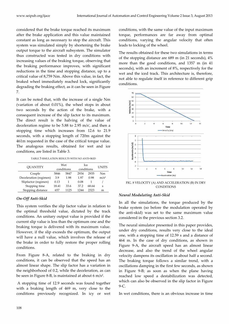
From Figure 8-A, related to the braking in dry conditions, it can be observed that the speed has an almost linear shape. The slip factor has a variation in the neighborhood of 0.2, while the deceleration, as can be seen in Figure 8-B, is maintained at about 6 m/s².
A stopping time of 12.9 seconds was found together with a braking length of 469 m, very close to the conditions previously recognized. In icy or wet
conditions, with the same value of the input maximum torque, performances are far away from optimal conditions, varying the angular velocity that often leads to locking of the wheel.
The results obtained for these two simulations in terms of the stopping distance are 689 m (in 21 seconds), 4% more than the good conditions, and 1357 m (in 41 seconds), with an increment of 8%, respectively for the wet and the iced track. This architecture is, therefore, not able to regulate itself in reference to different grip conditions.
FIG. 8 VELOCITY (A) AND ACCELERATION (B) IN DRY
CONDITIONS
Neural Modulating Anti-Skid
In all the simulations, the torque produced by the brake system (so before the modulation operated by the anti-skid) was set to the same maximum value considered in the previous section 3.2.
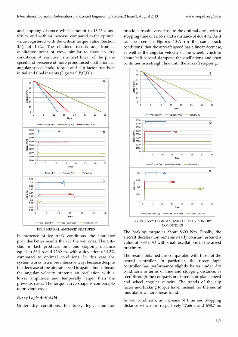
The neural simulator presented in this paper provides, under dry conditions, results very close to the ideal one, with a stopping time of 12.59 s and a distance of 464 m. In the case of dry conditions, as shown in Figure 9-A, the aircraft speed has an almost linear decrease, and also the trend of the wheel angular velocity dampens its oscillation in about half a second. The braking torque follows a similar trend, with a oscillations damping in the first few seconds, as shown in Figure 9-B; as soon as when the plane having reached low speed a destabilization was detected, which can also be observed in the slip factor in Figure 9-C.
In wet conditions, there is an obvious increase in time
International Journal of Automation and Control Engineering Volume 2 Issue 3, August 2013 www.seipub.org/ijace
109
and stopping distance which amount to 18.75 s and 670 m, and with an increase, compared to the optimal value registered with the critical torque value (Section 3.1), of 1.9%. The obtained results are, from a qualitative point of view, similar to those in dry conditions. A variation is almost linear of the plane speed and presence of more pronounced oscillations in angular speed, brake torque and slip factor trends at initial and final instants (Figures 9(B,C,D))
FIG. 9 NEURAL ANTI-SKID FEATURES
In presence of icy track conditions, the simulator provides better results than in the wet ones. The anti-skid, in fact, produces time and stopping distance equal to 36.9 s and 1260 m, with a deviation of 1.3% compared to optimal conditions. In this case the system works in a more intensive way, because despite the decrease of the aircraft speed is again almost linear, the angular velocity presents an oscillation with a lower amplitude and temporally larger than the previous cases. The torque curve shape is comparable to previous cases.
Fuzzy Logic Anti-Skid
Under dry conditions, the fuzzy logic simulator
provides results very close to the optimal ones, with a stopping time of 12.66 s and a distance of 468.4 m. As it can be seen in Figures 10-A (in the same track conditions) that the aircraft speed has a linear decrease, as well as the angular velocity of the wheel, which in about half second dampens the oscillations and then continues in a straight line until the aircraft stopping.
FIG. 10 FUZZY LOGIC ANTI-SKID FEATURES IN DRY
CONDITIONS
The braking torque is about 8600 Nm. Finally, the aircraft deceleration remains nearly constant around a value of 5.88 m/s2 with small oscillations in the arrest proximity.
The results obtained are comparable with those of the neural controller. In particular, the fuzzy logic controller has performance slightly better under dry conditions in terms of time and stopping distance, as seen through the comparison of trends of plane speed and wheel angular velocity. The trends of the slip factor and braking torque have, instead, for the neural modulator, a more linear trend.
In wet conditions, an increase of time and stopping distance which are respectively 17.66 s and 658.7 m,
www.seipub.org/ijace International Journal of Automation and Control Engineering Volume 2 Issue 3, August 2013
110
has been revealed. However, the velocity and the angular speed trends remained quite linear. The torque stands around values close to 5700 Nm and the deceleration takes a value around 3.92 m/s2. There is also an increase of the oscillations compared to dry conditions to the initial and final landing instants.
Globally, the brake modulator based on fuzzy logic presents, in wet conditions, anti-skid performance slightly higher than that in the case of the neural controller, in relation to the values of both stopping time and distance. Although the trends of other analyzed variables did not show substantial differences between the two different simulators developed, for the neural simulator more pronounced fluctuations of the angular speed, the braking torque and the slip factor were observed.
In icy condition, finally, the fuzzy logic-based controller provided responses comparable to those related to the case of a wet track, with a linear decrease of the aircraft speed and the presence of initial and final oscillations.
The time and stopping distance are respectively 35.56 s and 1246 m. The braking torque is about 2880 Nm and the slip factor maintained at around 0.085%. Finally, the deceleration has a value of about 1.97m/s2.
Even in icy conditions, the controller developed through the use of fuzzy logic has provided slightly higher performance with respect to the neural one, in relation to both stopping time and distance of the aircraft. Similar behavior was found for the braking torque and the slip factor values.
Sensitivity Analysis
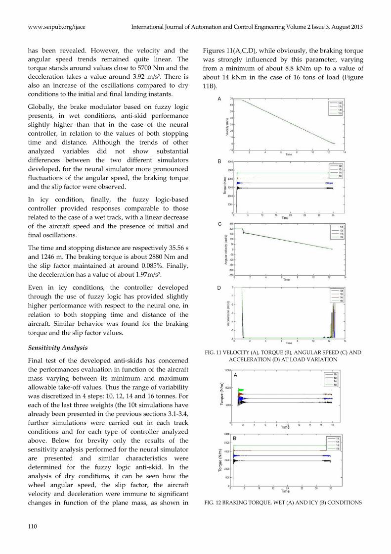
Final test of the developed anti-skids has concerned the performances evaluation in function of the aircraft mass varying between its minimum and maximum allowable take-off values. Thus the range of variability was discretized in 4 steps: 10, 12, 14 and 16 tonnes. For each of the last three weights (the 10t simulations have already been presented in the previous sections 3.1-3.4, further simulations were carried out in each track conditions and for each type of controller analyzed above. Below for brevity only the results of the sensitivity analysis performed for the neural simulator are presented and similar characteristics were determined for the fuzzy logic anti-skid. In the analysis of dry conditions, it can be seen how the wheel angular speed, the slip factor, the aircraft velocity and deceleration were immune to significant changes in function of the plane mass, as shown in
Figures 11(A,C,D), while obviously, the braking torque was strongly influenced by this parameter, varying from a minimum of about 8.8 kNm up to a value of about 14 kNm in the case of 16 tons of load (Figure 11B).
FIG. 11 VELOCITY (A), TORQUE (B), ANGULAR SPEED (C) AND
ACCELERATION (D) AT LOAD VARIATION
FIG. 12 BRAKING TORQUE, WET (A) AND ICY (B) CONDITIONS
International Journal of Automation and Control Engineering Volume 2 Issue 3, August 2013 www.seipub.org/ijace
111
In wet conditions, a change of the braking torque was determined from about 5.5 kNm up to a maximum of about 9.8 kNm (Figure 12(A)), while in the case of icy track, a variation from a minimum of about 2.9 kNm up to a maximum of about 5.7 kNm was found (Figure 12(B)).
Conclusions
The main purpose of the present study was the development of intelligent anti-skids, for business jet, capable to guarantee optimal brake conditions during landing process, which means that the brake modulation has to provide, for all track conditions and during all the deceleration phase, a friction coefficient close to its maximum value avoiding wheels blockage and optimizing stopping time and distance.
The controllers, developed by applying CI techniques as ANNs and FL, are able to ensure the required optimal braking performance in all environmental conditions, avoiding wheels blockage and, at the same time, obtaining substantial improvements in terms of stopping space and time.
The performance validation was carried out, related to a particular business jet, through a wide simulation campaign, considered as reference cases absence of brake modulation and on-off anti-skid. Compared to these solutions and particularly to the on-off anti-skid, neural and fuzzy modulating systems have shown significant reduction of time and space of arrest, with no locking of the wheels. Moreover, the same systems performed a progressive and regular reduction in wheels angular speed and a significant reactivity, capable to adapt instantly to any sudden change of the friction coefficient.
A comparison between FL and neural anti-skids, in terms of braking time and distance up to aircraft arrest, resulted in FL controller greater performance in case of wet and icy conditions, while slightly lower in case of dry asphalt.
Furthermore, the developed anti-skids achieved the targets of real-time computation and reduction of inputs parameters. In fact, they have reduced to 3 and further to 2 respectively in the case of FL and neural anti-skid.
It was entailed that only two sensors were necessary, as example, for implementation of the neural anti-skid (evaluation of slip factor and aircraft deceleration current values), with less failure risk and maintenance need beyond that cost reduction. Finally, both anti-
skids operated directly on the mechanical torque supplied by the brake system, so they can be used for different brake typologies.
ACKNOWLEDGEMENTS
O.M.A. S.p.a. is acknowledged for useful discussions and positive contribution to this work.
REFERENCES
Bill K., Breuer B. J.; Brake Technology Handbook, 2008
Drakunov S. Ozguner, U., Diz P., Ashraj B.; ABS control
using optimum search via sliding modes, Proceedings of
the 33rd Conference on Decision and Control WA-16
10100 Lake hens Vista, FL -December 1994
Gualdi S., Morandini M., Ghiringhelli G.L.; Anti-skid
induced aircraft landing gear instability, Areospace
Science and Technology, 12 (2008), pp. 627-637.
Harifi A., Aghagolzadeh A., Alizadeh G., Sadeghi M.;
Designing a sliding mode controller for slip control of
antilock brake systems, Transportation Research Part C,
16 (2008), pp. 731–741.
Layne J.R., Passino K.M., Yurkovich S.; Fuzzy learning
control for anti-skid braking systems, IEE Transactions
on control systems technology, Vol. 1, No. 2, June 1993.
Matusko J., Petrovic I., Peric N.; Neural network based
tire/road friction force estimation, Engineering
Applications of Artificial Intelligence, 21 (2008), pp. 442-
456.
Mauer G. F.; A Fuzzy Logic Controller for an ABS Braking
System, IEEE Transactions on Fuzzy systems, Vol. 3, No.
4, November 1995.
Milde M.; International Air Law and ICAO, 2008
Mirzaeinejad H., Mirzaei M.; A novel method for non-linear
control of wheel slip in anti-lock braking systems,
Control Engineering Practice, 18 (2010), pp. 918-926.
Poursamad A.; Adaptive feedback linearization control of
antilock braking systems using neural networks,
Mechatronics, 19 (2009), pp. 767-773.
Somakumar R., Chandrasekar J.; Intelligent anti-skid brake
controller using a neural network, Pergamon, Control
enginnering practice, 7 (1999), pp. 611-621.
Szurovy, G., Cessna Citation Jets, 2000.
Topalov A. V., Oniz Y., Kayacan E., Kaynak O.; Neuro-fuzzy
control of antilock braking system using sliding mode
www.seipub.org/ijace International Journal of Automation and Control Engineering Volume 2 Issue 3, August 2013
112
incremental learning algorithm, Neurocomputing, 74
(2011), pp. 1883-1893.
Ursu I., Ursu F.; An intelligent ABS control based on Fuzzy
Logic. Aircraft application, Proceedings of the
International Conference on Theory and Applications of
Mathematics and Informatics – ICTAMI 2003, Alba Iulia.
Wu M., Shih M.; Simulated and experimental study of
hydraulic anti-lock braking system using sliding-mode
PWM control, Mechatronics, 13 (2003), pp. 331-351.
Yadav D., Singh C.V.K.; Landing response of aircraft with
optimal anti-skid braking, Journal of sound and
Vibration, 3 (1995), pp. 401-416.
Nomenclature
λ: slip factor Φx: horizontal constrain reaction (N) Φn: vertical constrain reaction (N) μ: friction coefficient ω: wheel angular speed (rad/s) ω0: initial wheel angular speed (rad/s) a: distance between the front undercarriage and
the barycenter (m) b: distance between the main undercarriage and the barycenter (m) Dn: wheel nominal diameter (m) g: gravitational constant (m/s2) I: wheel inertia (kg*m2) k: braking correction factor l: distance between the front and main undercarriage (m) P: weight force (N) M: aircraft mass (kg) m: wheel mass (kg) nout: number of output neurons ntest: data set number of elements R: wheel radius (m) Rp: rear wheel constrain reaction (N) SSE: sum squared error T: brake torque (Nm) V: aircraft velocity (m/s) V0: initial aircraft velocity (m/s) RMS: root mean square