Embed Size (px)
Citation preview
Received July 16, 2021, accepted August 2, 2021, date of publication September 3, 2021, date of current version September 28, 2021.
Digital Object Identifier 10.1109/ACCESS.2021.3110159
An Advanced Unmanned Aerial Vehicle (UAV)Approach via Learning-Based Control forOverhead Power Line Monitoring:A Comprehensive ReviewHUSAM A. FOUDEH 1, PATRICK CHI-KWONG LUK 1, (Senior Member, IEEE),AND JAMES F. WHIDBORNE 2, (Senior Member, IEEE)1Electric Power and Drives Group, Cranfield University, Cranfield MK43 0AL, U.K.2Centre for Aeronautics, Cranfield University, Cranfield MK43 0AL, U.K.
Corresponding author: Patrick Chi-Kwong Luk ([email protected])
This work was supported in part by Cranfield University, and in part by the Engineering and Physical Sciences Research Council (EPSRC),U.K., titled ‘‘Decarbonising Transport through Electrification, a Whole System Approach,’’ under Grant EP/S032053/1.
ABSTRACT Detection and prevention of faults in overhead electric lines is critical for the reliabilityand availability of electricity supply. The disadvantages of conventional methods range from cumbersomeinstallations to costly maintenance and from lack of adaptability to hazards for human operators. Thus,transmission inspections based on unmanned aerial vehicles (UAV) have been attracting the attention ofresearchers since their inception. This article provides a comprehensive review for the development ofUAV technologies in the overhead electric power lines patrol process for monitoring and identifying faults,explores its advantages, and realizes the potential of the aforementioned method and how it can be exploitedto avoid obstacles, especially when compared with the state-of-the-art mechanical methods. The reviewfocuses on the development of advanced Learning Control strategies for higher manoeuvrability of thequadrotor. It also explores suitable recharging strategies and motor control for improved mission autonomy.
INDEX TERMS UAVs, quadrotor, iterative learning control (ILC), power-line detection, insulator, highvoltage, tracking control, climbing robots, autonomous recharging, wireless power transfer.
I. INTRODUCTIONElectrical power lines are a vital component of the powersector and it is essential that preventive maintenance ofHigh Voltage (HV) transmission lines be carried out in asafer and more efficient way to meet consumer demand.Widespread electrification in the transportation and energysectors in the coming decades will exacerbate the costs of anypower transmission failure. However, overhead electricitylines face numerous problems, including snow accumulationon exposed electrical conductors and constant threats of col-lapse to the system architecture due to harsh conditions. Thistypically causes loss of one or more phases [1]–[6]. Trans-mission lines alone represent between 5 and 10 percent of thetotal cost of electricity. Significant damage may occur to theExtra High Voltage (EHV) or High Voltage (HV) network;
The associate editor coordinating the review of this manuscript andapproving it for publication was Fei Chen.
for instance, in France in December 1999, approximately8 percent of the EHV/HV transmission network was outof action and it took 6 months to complete repairs to thelines. The total cost was estimated to be 150 million euros.However, the economic losses of such prolonged repairs willbe multiplied significantly when disruptions are cascaded tomore electrified transport and energy systems in future. Thiscould have been resolved more rapidly by swifter identifica-tion of faults [7], [8].
In recent years, both climbing robots and unmanned aerialvehicles (UAVs) have been used as automated systems forlocating faults in overhead electricity lines, in order to addressthe limitations of traditional methods. There are challengesin applying such automated approaches, however, due tothe structure and components of the system, which com-prises power lines, insulators and pylons of various structures.In addition, UAVs are restricted by the non-contact sensingtechnologies they can use [9]–[11].
130410 This work is licensed under a Creative Commons Attribution 4.0 License. For more information, see https://creativecommons.org/licenses/by/4.0/ VOLUME 9, 2021
H. A. Foudeh et al.: Advanced UAV Approach via Learning-Based Control for Overhead Power Line Monitoring
Accordingly, there have been numerous research studiesconducted to automate inspect power systems approaches;however, there is a paucity of comprehensive publishedreviews which highlight certain issues (i.e., maintenance,inspection) for different approaches to the problem [12]–[16].This is mainly because the technology is still undergoingcontinuous research and development and there exists nounified framework of applications.
The main contribution of this article is to present a com-prehensive overview of the different possibilities, challenges,and obvious limitations and realistic scenarios to improveautonomous robotics in power systems (particularly UAVs)for inspection processes. Furthermore, this paper differs fromexisting literature by extending the scope of study in the fol-lowing aspects: this paper (i) covers various major inspectiontechniques based on autonomous robotics in power systems,namely, traditional operational and environmental methods,electromechanical, UAVs, (ii) reviews the existing iterativelearning control approaches in UAVs applications and possi-bility future trends to used it in inspection approaches, and(iii) emphasizes on the autonomous recharging (i.e., wirelesscharger from power lines) strategies in UAVs applications toenhance inspection approaches based on robotics.
This paper provides a comprehensive summary of theeffectiveness and weaknesses associated with conventionalmethods as the typical primary solutions used in relation toaddressing inspection issues of electric power systems. Then,advanced existing technologies such as robots and UAVs aspromising systems are screened and compared. The pros andcons of each approach are adopted in comparison with regardto the judgement of fault points by vision or other methods,data collection, and the problem of trajectory tracking whenusing both approaches to power system inspection.
Another goal is to achieve high performance trajectorytracking and avoid most of the limitations in the trackingproblem addressed in this paper. Since this is a challengingtask, it will require more advanced controllers than currentlyexist, and we propose a new solution based on iterativelearning control (ILC) as an approach capable of performinghigh traceability on the network and coping with weather andexogenous disturbances. In particular, the repetitive natureof power line geometries lends itself to this approach duringinspection. In addition, in this paper, a review is conductedon automatic recharging systems for UAV batteries as anessential part of the durability of the work and the extensionof the duration of the mission. This has particularly receivedlittle attention in the literature, especially for achieving fullautomatic trajectory tracking and uninterrupted performanceon power lines.
The paper is organized as follows. In Section II, it describesthe types of fault commonly encountered in power systems,reviews the existing and conventional fault location tech-niques, and describes their advantages and limitations. Addi-tionally, the quadrotor application is discussed for both visionand non-vision based sensing approaches in Section III.In Section IV, the iterative learning control (ILC) algorithm
is discussed and reviewed for UAV applications. Section Vreviews automatic recharging system for power line inspec-tion UAVs. Finally, Section VI draws conclusions and pro-vides suggestions for future work.
II. METHODS OF INSPECTION FOR FAULTS ON POWERSYSTEMIn this section, we provide a review of current knowledgeabout the components of a power system as well as classi-fication of faults which covers the principles of inspectionstechniques, the most popular methods of inspection faultsidentified by the Distribution Network Operators (DNOs)and Transmission Network Operators (TNOs). In addition,we introduce the inspections propagation models for UAVsand robot-based approaches.
A. CURRENT METHODS OF INSPECTION FAULTS BY DNOsAND TNOsThe power system components most susceptible to naturalhazards are the transmission and distribution lines, whichhave the most extreme working conditions and are subjectto numerous problems. This poses significant challenges forDNOs and TNOs, so it is important to clarify the basicdifference between them. The difference lies in these factors:the type of geometric structure, power flow, responsibilities,safety, maintenance, and inspection. In the case of DNOs,a lower voltage and long distance with unidirectional powerflow are considered on a local scale. By contrast, TNOs focuson high voltage and long distance by bidirectional power flowof major industrial customers.
An example of TNO challenges, occurs in rough terrainssuch as mountainous areas in the Liangshan region of China,and the installed systemmay cause repeated failure in 500 kVtransmission lines over a distance of 3 km [17]. This is due toa small error generating a sequence of failures extending longdistances until they find a point of failure. The maintenancecrew may have to walk as far as 6 km in mountainous areasto determine the exact location of the fault point.
In 2003, power grid outages in the northeastern UnitedStates and Canada demonstrated that transmission faults canhave a devastating impact on the national-grid, as well ason interdependent systems such as telecommunications net-works [18]–[20]. A recent study showed that the failure oftransmission lines during winter caused by snow accumula-tion on aluminium conductor steel-reinforced (ACSR) cablein the area of Jordan caused severe difficulties for the main-tenance crew [21].
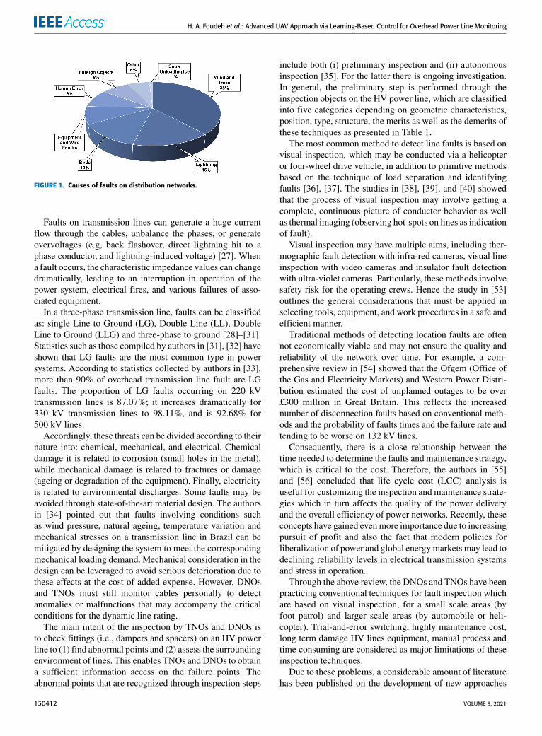
The complexity of most power grids often makes iden-tifying faults difficult, especially as there are many causesand types of power failure in an overhead transmissionline. Examples include storms, lightning, freezing rain andfog, partial discharges (corona), insulation breakdown, shortcircuits caused by birds or other external objects com-ing into contact with the line, or tree branches hitting thelines [22]–[26]. These causes are summarised in Figure 1.
VOLUME 9, 2021 130411
H. A. Foudeh et al.: Advanced UAV Approach via Learning-Based Control for Overhead Power Line Monitoring
FIGURE 1. Causes of faults on distribution networks.
Faults on transmission lines can generate a huge currentflow through the cables, unbalance the phases, or generateovervoltages (e.g, back flashover, direct lightning hit to aphase conductor, and lightning-induced voltage) [27]. Whena fault occurs, the characteristic impedance values can changedramatically, leading to an interruption in operation of thepower system, electrical fires, and various failures of asso-ciated equipment.
In a three-phase transmission line, faults can be classifiedas: single Line to Ground (LG), Double Line (LL), DoubleLine to Ground (LLG) and three-phase to ground [28]–[31].Statistics such as those compiled by authors in [31], [32] haveshown that LG faults are the most common type in powersystems. According to statistics collected by authors in [33],more than 90% of overhead transmission line fault are LGfaults. The proportion of LG faults occurring on 220 kVtransmission lines is 87.07%; it increases dramatically for330 kV transmission lines to 98.11%, and is 92.68% for500 kV lines.
Accordingly, these threats can be divided according to theirnature into: chemical, mechanical, and electrical. Chemicaldamage it is related to corrosion (small holes in the metal),while mechanical damage is related to fractures or damage(ageing or degradation of the equipment). Finally, electricityis related to environmental discharges. Some faults may beavoided through state-of-the-art material design. The authorsin [34] pointed out that faults involving conditions suchas wind pressure, natural ageing, temperature variation andmechanical stresses on a transmission line in Brazil can bemitigated by designing the system to meet the correspondingmechanical loading demand. Mechanical consideration in thedesign can be leveraged to avoid serious deterioration due tothese effects at the cost of added expense. However, DNOsand TNOs must still monitor cables personally to detectanomalies or malfunctions that may accompany the criticalconditions for the dynamic line rating.
The main intent of the inspection by TNOs and DNOs isto check fittings (i.e., dampers and spacers) on an HV powerline to (1) find abnormal points and (2) assess the surroundingenvironment of lines. This enables TNOs and DNOs to obtaina sufficient information access on the failure points. Theabnormal points that are recognized through inspection steps
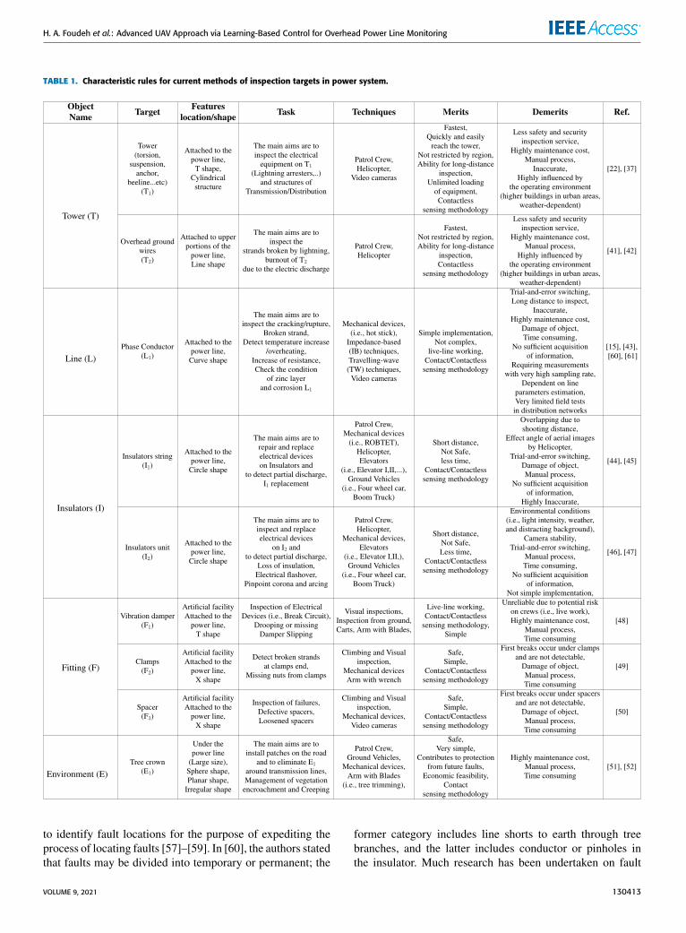
include both (i) preliminary inspection and (ii) autonomousinspection [35]. For the latter there is ongoing investigation.In general, the preliminary step is performed through theinspection objects on the HV power line, which are classifiedinto five categories depending on geometric characteristics,position, type, structure, the merits as well as the demerits ofthese techniques as presented in Table 1.
The most common method to detect line faults is based onvisual inspection, which may be conducted via a helicopteror four-wheel drive vehicle, in addition to primitive methodsbased on the technique of load separation and identifyingfaults [36], [37]. The studies in [38], [39], and [40] showedthat the process of visual inspection may involve getting acomplete, continuous picture of conductor behavior as wellas thermal imaging (observing hot-spots on lines as indicationof fault).
Visual inspection may have multiple aims, including ther-mographic fault detection with infra-red cameras, visual lineinspection with video cameras and insulator fault detectionwith ultra-violet cameras. Particularly, these methods involvesafety risk for the operating crews. Hence the study in [53]outlines the general considerations that must be applied inselecting tools, equipment, and work procedures in a safe andefficient manner.
Traditional methods of detecting location faults are oftennot economically viable and may not ensure the quality andreliability of the network over time. For example, a com-prehensive review in [54] showed that the Ofgem (Office ofthe Gas and Electricity Markets) and Western Power Distri-bution estimated the cost of unplanned outages to be over£300 million in Great Britain. This reflects the increasednumber of disconnection faults based on conventional meth-ods and the probability of faults times and the failure rate andtending to be worse on 132 kV lines.
Consequently, there is a close relationship between thetime needed to determine the faults and maintenance strategy,which is critical to the cost. Therefore, the authors in [55]and [56] concluded that life cycle cost (LCC) analysis isuseful for customizing the inspection and maintenance strate-gies which in turn affects the quality of the power deliveryand the overall efficiency of power networks. Recently, theseconcepts have gained evenmore importance due to increasingpursuit of profit and also the fact that modern policies forliberalization of power and global energymarkets may lead todeclining reliability levels in electrical transmission systemsand stress in operation.
Through the above review, the DNOs and TNOs have beenpracticing conventional techniques for fault inspection whichare based on visual inspection, for a small scale areas (byfoot patrol) and larger scale areas (by automobile or heli-copter). Trial-and-error switching, highly maintenance cost,long term damage HV lines equipment, manual process andtime consuming are considered as major limitations of theseinspection techniques.
Due to these problems, a considerable amount of literaturehas been published on the development of new approaches
130412 VOLUME 9, 2021
H. A. Foudeh et al.: Advanced UAV Approach via Learning-Based Control for Overhead Power Line Monitoring
TABLE 1. Characteristic rules for current methods of inspection targets in power system.
to identify fault locations for the purpose of expediting theprocess of locating faults [57]–[59]. In [60], the authors statedthat faults may be divided into temporary or permanent; the
former category includes line shorts to earth through treebranches, and the latter includes conductor or pinholes inthe insulator. Much research has been undertaken on fault
VOLUME 9, 2021 130413
H. A. Foudeh et al.: Advanced UAV Approach via Learning-Based Control for Overhead Power Line Monitoring
locators and protective relays, which can estimate the loca-tion of both temporary and permanent faults. Mechanicaldamage is not always obvious following permanent faults.Conversely, temporary faults can be cleared automatically ifthe location of the fault is identified. Thus, temporary faultscan expedite the restoration of the line or be estimated withreasonable accuracy [61].
Researchers have been trying to find reliable and effi-cient ways for fault location identification. The currentlyavailable conventional methods in fault location methods canbe broadly classified under three headings; (i) Impedance-Based (IB) techniques [62], (ii) Travelling-Wave (TW) tech-niques [63] and (iii) artificial intelligent techniques [64]–[66].For these techniques, it is necessary to sense the magneticfield caused by current flows through a cable or conductor.A device such as a fault indicator can be installed either in asubstation or on a tower over an overhead electrical transmis-sion line. These have several merits and demerits in use withcomposed fault location identification techniques [61].
1) IB-BASED TECHNIQUESThe IB methods are widespread among electric power util-ities due to their simplicity. Typically, in IB methods faultlocation algorithms use fundamental frequency current andvoltage measurements. Consequently, several approaches aredeveloped based on IB methods such as reactive component(this method is not valid for practical cases) [67], Takagialgorithm (the method was tested in practical transmissionline systems) [68] and Girgis method (includes a calculationerror due to repetitive iterations) [69].
2) TW-BASED TECHNIQUESSeveral studies focus on fault location identification tech-niques which can use TW techniques. Either the transientcreated by a fault is captured or impulses are injected intothe line and the reflected travelling wave is detected with atime-domain reflectometer. As the fault signal obtained at theend of the transmission line is highly distorted with noise,modern signal processing techniques are required, such asthe use of wavelets [63], [70], [71]. However, these methodsfully depend on an assumption that the parameters of thetransmission line are uniform.
In the above subsection, we have provided an overview ofthe main traditional methods inspection of power systems.In the next subsection, we will address the limitations oftraditional methods and attention will be paid to promisingnew techniques. Climbing robot-based approaches have beenused to produce an automated system in the inspection powersystem. This is a challenging task due to the structure andcomponents of the system, which comprises power lines(single or bundle), insulators and pylons of various structures.
B. ELECTROMECHANICAL METHODS FOR POWERSYSTEM INSPECTIONThe accuracy of judging the fault points in power sys-tems using traditional approaches can be influenced by
(i) manpower shortages, (ii) experience of the workers,(iii) tracking process during the inspection, (iv) skippingobjects, and (v) hidden objects. The accuracy can beimproved by using a robotic approach by following the judge-ment of fault points by vision or other methods and trajectorytracking when using robots. The following two problems willbe reviewed.
1) JUDGEMENT OF FAULT POINTS USING ROBOTSRobotic devices or climbing robots were first developedfor the inspection of transmission lines over two decadesago. Their introduction was motivated by safety factors,the need to access remote and difficult areas and increasedoperational efficiency. Due to their direct contact with thesystem, climbing robots have only been designed specifi-cally for a fixed configuration of cable [14], fittings [46]and pylon features [72]. The following papers describe theevolution of climbing robots during inspection and faultpoints via various methods (i.e. eddy current, vision, ther-mal), starting with judgement at a single fault point (singlepower line, or insulators) and then judging the combinationof fault points (obstacles and dealing with different cablestructures).
A climbing robot that uses wheels to travel along andinspect a single power line was described in [73]. Weighing17.8 kg, this robot uses eddy current sensors to detect corro-sion in live ACSR cables and was developed by Light SESA,a power distributor in Brazil. This method is able to detect theremaining thickness of the zinc layer over the cables, giving acondition judgement on fault points. Specifically, a decreasein layer thickness indicates a fault. However, the downsidemethod is corona interference, which affects (i) measure-ments, (ii) wireless links, (iii) and electronic circuits.
The robotic device in [74] again focused on detectingcorrosion on a single power line via a vision system with asingle camera and adding a cleaning option. The difference isthat the vision technique detects types of debris (i.e. salt builtup on lines, dust, smoke, and polluting winds) that lead tocorrosion in [74], while the eddy technique was used to assessthe coating thickness and can be applied on wet surfaces [73].However, the vision system has less data collection and noreal-time detection of faults, which in turn reduces the visualdata collected on fault points.
Meanwhile, the robot in [75], [76] focused on the thermalmethod to detect a single power line and add an obstacle faultsuch as counterweights. The system was equipped with twocameras: a visible-light camera and thermal infrared camera.The objective was to acquire three-phase conductor and insu-lator data in the case of live lines and apply image processingto highlight expected faults. Furthermore, the robot aims toidentify hot spots by distributing temperature on thermalimages. However, the incorporation of the thermal method injudging the combination of fault points (three-phase conduc-tors and insulators) also brings along a series of challengingissues related to measurements, implementation, extraction,and identification.
130414 VOLUME 9, 2021

H. A. Foudeh et al.: Advanced UAV Approach via Learning-Based Control for Overhead Power Line Monitoring
Finally, in [77], the climbing robot operated on live powerlines and obstacles to inspect outer-layer broken strand cablesusing the vision method. The robot is equipped with a SonyFCBEX980S camera with a mechanical part that is able topan-and-tilt. The main advantage of this method is that itmaximizes the rate of defect detection by 99% at the faultpoint due to its proximity to the cables and camera widefield of view (±360◦,±90◦). Furthermore, the measurementsare obtained accurately using 26× optical zoom with anadjustable iris. However, the vision method mainly deals withthe exposed broken outer layer, while the broken inner layerbelow the high-pressure points is often overlooked.
It is crucial to note that the studies conducted in[73]–[76] obtained measurements and judgements of faultpoints only under normal weather conditions (a clear line ofsight to operate properly), while themeasurements and judge-ments were performed successfully under very challengingconditions (i.e. windy conditions up to 70 km/h, temperaturesfrom −15 ◦C to +35 ◦C ) in [77].
2) TRAJECTORY TRACKING USING ROBOTSThe following papers describe the evolution of climbingrobots, startingwith inspection along a single power line, thenadding obstacle avoidance, and dealing with different cablestructures. Finally, robots with the ability to transfer from thecable to a specific type of pylon are discussed.
A climbing robot that performs power line tracking with ageneric controller from a ground based operator is describedin [73]. In this tracking system, a simple horizontal trajec-tory is achieved within a single part between two towers.Furthermore, the robot can correctly track a power line bymoving forward and backward. However, the climbing robotis requires a four-person crew to be installed manually onthe line conductor using a hot stick. Additionally, this deviceis incapable of crossing over towers and overcoming mostobstacles due to the use of a generic controller and has amaximum line voltage of 350 kV. Moreover, the trackingperformance is slow and takes approximately 2.5 hours toachieve the horizontal trajectory.
The robotic device in [74] tackled power line inspectionand added the capability to avoid obstacles. Weighing just13.7 kg, the prototype uses V-groovedwheels to grip the cableand successfully move down a line, passing obstacles such assplices. It was only tested under laboratory conditions andembeds only basic functions: PID control to obtain forwardand backward motion via trajectory tracking and an ultra-sonic sensor used for open-loop motion control. Additionally,the battery takes approximately 60 mins to charge fully.
Another device, designed by Shanghai University anddescribed in [75], [76], again adds obstacle avoidance anduses a more sophisticated structure to increase its speed.This robot weighs 38 kg and takes eight seconds to moveover spacers and counterweights. The structure has two armswith three degrees of freedom, enabling the robot to avoidobstacles by adjusting the arm length. Moreover, trajec-tory tracking is improved by combining flexible and rigid
multibody dynamics theory to avoid obstacles. This sophis-ticated structure only works with 110 kV transmissionlines, however, and moves very slowly with a battery lifeof 6.0 hours. In addition, this study only considered a singlepower line.
In [77], the climbing robot’s ability is expanded to trans-fer from the cable to a suspension tower, with the devicethen moving manually from one side of a tower to theother. The device is controlled by a semi-mobile groundstation and was developed by Hydro-Québec TransÉnergie inCanada. Named ‘‘LineScout Technology’’ (LT), this mechan-ical device attaches to HV cables and weighs 100 kg. Theprototype has been tested in field conditions, where it hasbeen shown to overcome a variety of obstacles in an efficientmanner.
Unlike the above two studies, the robots in [77] can sustainan accurate tracking performance by tracking two predefinedtrajectories in two operation modes. The tracking strategy isperformed via inverse kinematics and controlling the linearvelocities (x and y) and its angular velocity (φ), which can becomputed in equation 1. By relaxing the problem in this way,the robot can perform the Cartesian mode for trajectory 1 andthe joint control mode for trajectory 2 at a defined speed,as illustrated in Figure 2. LT is only semiautonomous, how-ever, andwas designed to inspect a single type of transmissionline (735 kV). It is also complex and expensive.
Eω =
θ1θ2ρ
=−
1l1 sin θ1
0 0
1l1 sin θ1
0 1
cos θ1sin θ1
1 0
· xyφ
(1)
where Eω is the vector of the joint velocities.
FIGURE 2. Behaviour of joint velocities at input cartesian speedof 0.02 m/s in horizontal tracking.
VOLUME 9, 2021 130415
H. A. Foudeh et al.: Advanced UAV Approach via Learning-Based Control for Overhead Power Line Monitoring
A similar approach was employed in the design of the‘‘Expliner’’ system, developed by the HiBot Corporation inJapan [47], [78]. In this case, however, the robotic device addsthe capability of performing more detailed inspection of bun-dled conductors. The prototype has a carbon-fibre structurewith a T-shaped base and two degrees of freedom, enablingit to travel down live transmission lines while overcomingobstacles in its path. At least seven people are needed to loadthe Expliner and attach it to a cable, a process that takes abouttwo and a half hours. This operation must be repeated at eachtower. It is, however, possible to pre-equip the tower with theclamps, bases and pulleys necessary to lift the equipment,which reduces the preparation time. As well as the cost, timeand complexity, this robot is designed only for the specifictype of bundled transmission lines used in Japan.
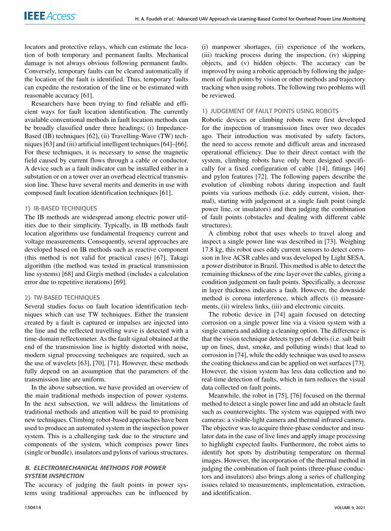
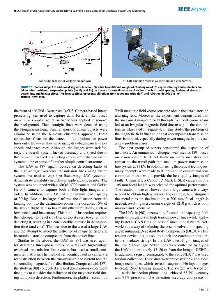
Mechanical inspection robots have, therefore, been suc-cessfully implemented on transmission lines and comprise areasonably reliable method to assess the physical conditionof cables. They have significant disadvantages, however – themost sophisticated devices are specialized for one type of HVand are very large, complex and expensive. In addition, theyuse a balancing mechanism to ensure dynamical stability butthis increases their overall weight and makes them very slow.These issues are readily illustrated in Figure 3 [47].
Other important constraints exist. Each robot must be man-ually attached and can only be used on one section of a trans-mission line (i.e., between each set of towers). The towers onwhich the robot is to be installed may only be accessible oververy bumpy roads. In addition, live-line installation methodsmay require boom trucks, helicopters and remote manipula-tion with insulated sticks. Finally, mechanical shocks duringtransportation or field installation may damage the electronicboards and key mechanical components. The inability totrack the transition between lines and pylons is another fun-damental limitation. Furthermore, little work has yet beendone to develop additional technologies to enable robots totrack bundled conductors, bypass strain pylons and pylon/linedocking.
In the above subsection, we provided an overview of powersystem inspection using robots, including 1) the judgment offault points by vision or other methods and 2) the problemof trajectory tracking. In the next section, attention will begiven to new promising UAV techniques in power systeminspection. This is a challenging task due to the structure andcomponents of the system, which is composed of power lines,insulators, and pylons of various structures.
III. DETECTION OF UAV POWER SYSTEMThe emergence of UAV technology has the potential toaddress the aforementioned limitations due to their inherentadvantages of cost, manoeuvrability, speed, and ease of setup.They also do not require contact and can attain the requiredheights and positions needed to perform major inspectiontasks. UAVs can also be operated in more severe weathercondition and can operate in places that are either dangerousor unreachable for humans [79]–[82]. This section reviews
the approaches employed in this area, which are generalizedto the specific problems of those focusing on the inspectionof fault points (i.e. power lines, pylons/insulators, and com-binations of those points), those focusing on data collection,and finally, those focusing on tracking control of UAVs.
A. DETECTION OF FAULT POINTSThis subsection reviews the approaches employed in this area,which are classified into those focusing on detecting faultpoints solely on a single component (a single power line orinsulators) and then detecting fault points on the combinationof components via various methods.
The study in [83] used a UAV with thermal imaging toinspect joints in power lines by analysing their tempera-ture, thereby avoiding costly service interruptions. The studyshowed that relevant temperature anomalies can be detectedin the electric lines and devices. Even from short distances,however, it was impossible to achieve accurate temperaturemeasurements of the electrical faults. The helicopter systemin [84] similarly used thermal imaging to inspect joints inpower lines, but focused on long-distance qualitative inspec-tion. The results showed that the joints have a higher temper-ature than other parts of the towers and can be detected ashot spots in thermal images. However, the accuracy achievedin both the studies was poor due to the large measurementspot size compared to the small target size, as well as the longmeasurement range, object reflection and weather conditions.Furthermore, neither study provided an in-depth analysis oftheir results. Although this inspection method allowed accessto hard-to-reach locations and increased inspection speed,it had many disadvantages. Because the helicopter was man-ually operated and used to process raw data, extraction wasless efficient and produced lower-quality data.
A smaller quadrotor was developed in [85] to again detectfaults on power lines, now using remote sensing spectral-spatial methods. The UAV was manually launched to findfault over a single cables from the ground. The UAV weighed1.5 kg and was fitted with a GoPro HD Hero2 camera usedfor inspection. This was different from [83] and [84], whichadopted a thermal method together with crude image process-ing (means poor quality of the inspection). The study in [85],considered both the K-means algorithm and ExpectationMaximization (EM) to classify the pixels into the power linesand non-power lines. This enhance the quality of detect faultsrather than the thermalmethod in [83] and [84] were unable todetect faults on single power lines with high accuracy due tothe presence of (1) heat absorbing (2) and emitting sourcesin the environment, leading to lower temperature varianceamong the power lines and background (non-power lines).
The UAV in [86], meanwhile, focused on the inspectionof medium-voltage power lines using vision based methods.This type of line has increased height and distance comparedto a distribution (low voltage) power line and requires astrain tower rather than a suspension tower. This provides agreater challenge, due to the additional supports of the straintower. Accordingly, a bigger UAV platform was selected in
130416 VOLUME 9, 2021
H. A. Foudeh et al.: Advanced UAV Approach via Learning-Based Control for Overhead Power Line Monitoring
FIGURE 3. Cables subject to additional sag with function, δ(x) due to additional weight of climbing robot. To express the sag various factors aretaken into considered: suspension points (i.e. P1 and P2) on tower, cross-sectional area of cables, L as horizontal spacing, horizontal stress ofpower line, and impact effect. This impact effect represents vibrations from robot and wind (left) and robot on double 315-kVcircuits (right) [47].
the form of a V-TOL Aerospace BAT-3. Camera-based imageprocessing was used to capture data. First, a filter basedon a pulse coupled neural network was applied to removethe background. Then, straight lines were detected usingthe Hough transform. Finally, spurious linear objects wereeliminated using the K-means clustering approach. Theseapproaches focus on the detect of fault points for powerlines only. However, they have many drawbacks, such as lowspeeds and inaccuracy. Although, the images were satisfac-tory, the overall system lacked accuracy and speed due tothe trade-off involved in selecting a more sophisticated visionsystem at the expense of a rather simple control structure.
The UAV in [87] again focused on detecting faults ofthe high-voltage overhead transmission lines using visionsystem, but used a large size fixed-wing UAV system todemonstrate feasibility in different application scenarios. Thesystem was equipped with a 6RQ/I-6000 camera and GoProHero 3 camera to capture both visible light images andvideo. In addition, the UAV had a maximum load capacityof 30 kg. Due to its large platform, the distance from thelanding point to the destination power line occupies 15% ofthe whole flight. It also has many other limitations, such aslow speeds and inaccuracy. This kind of inspection requiresthe helicopter to travel slowly and stop at every tower withoutdetecting it, resulting in a considerable increase in the inspec-tion time (and cost). This was due to the use of a large UAVand the attempt to avoid the influence of magnetic field andharmonic distortion component from the power line.
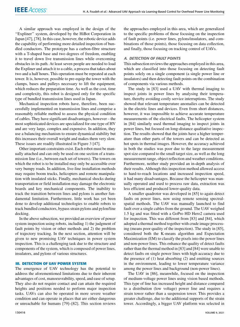
Similar to the above, the UAV in [88] was used againfor detecting three-phase faults on a 500-kV high-voltageoverhead transmission line system, but used a small com-mercial platform. The method can identify fault in cables viareconstruction between the transmission line current and thesurrounding magnetic field distribution. Compared with [87],the study in [88] conducted a scaled down indoor experimentthat aims to consider the influence of the magnetic field dur-ing fault point detection. Furthermore, the platform contains a
TMRmagnetic field vector sensor to obtain the data distortionand magnetic. Moreover, the experiment demonstrated thatthe measured magnetic field through five continuous spansled to an irregular magnetic field due to sag of the conduc-tors as illustrated in Figure 4. In this study, the problem ofthe magnetic field fluctuation that accompanies transmissionlines is omitted, especially during power outages. In this case,a new problem arises.
The next group of papers considered the inspection ofinsulators. An unmanned helicopter was used in [89] basedon vision system to detect faults on many insulators thatappear on the travel path in a medium power transmissionline system at 11 kV. In addition, using theoretical techniques,many attempts were made to determine the camera and lenscombination that would provide the best quality images offaults. Ultimately, a Canon 5D Mark II SLR camera with a105 mm focal length was selected for optimal performance.The results, however, showed that a large camera is alwaysneeded to obtain high accuracy. For example, to distinguishthe metal pins on the insulator, a 200 mm focal length isneeded, resulting in a camera weight of 1210 g which is bothmassive and expensive.
The UAV in [90], meanwhile, focused on inspecting faultpoints on insulators in high tension power lines while apply-ing Faster R-CNN (Region-based Convolutional Neural Net-works) as a way of reducing the costs involved in inspectingandmaintainingDead-EndBodyComponents (DEBC) (a fulltension device that is used to attach the conductor structureto the insulator string). In the UAV’s test flight, images ofthe live high-voltage power lines were collected by flyingthe UAV approximately 15–20 m from the imaged DEBCs.In addition, a sensor comparable to the Sony NEX 7 was usedfor data collection. These data were processed through simpleimage techniques, which served to augment 146 input imagesto create 2437 training samples. The system was tested on111 aerial inspection photos, and achieved 83.7% accuracyand 91% precision. The detection accuracy and precision
VOLUME 9, 2021 130417

H. A. Foudeh et al.: Advanced UAV Approach via Learning-Based Control for Overhead Power Line Monitoring
FIGURE 4. Height of phase C is subject to different vertical spacing sag S, which reflects varying over spans L in horizontal spacing which inturn lead to irregular magnetics with different heights for Phase C (left) and influence of irregular magnetic field distribution on horizontalxy-plane, where H is vector of magnetic field generated by one-phase transmission lines starting from heights of 20, 18, and 16 m (right).
were increased to 97.8% and 99.1% by adding 270 additionaltraining images and including a new insulator class. Both [89]and [90] were only interested in the inspection of insulatorsrather than the other system components, such as cables andpower pylons. They focused on improving the accuracy ofcamera solutions to allow objects at a distance. This needarose because the UAVs reviewed so far only used basic,generic controllers, meaning that a sophisticated camera wasnecessary.
The following papers expand the UAV scope to attemptdetection of the fault points on the combination ofcomponents.
The UAV in [91] was loaded with LiDAR and had a camerawith a resolution of 1280 × 1024 pixels. Both measured thecorrect distance to the power line. At a distance of 10 mfrom the power line, however, the line appeared as a 1 pixelwide ridge in the image as shown in Figure 5. Additionally,the results showed poor accuracy in terms of the appearanceof the 35mmpower line thickness versus the viewing distancefunction, as illustrated in Figure 6. ACSR cables appeared asa small line with insufficient detail to distinguish faults dueto the reliance on traditional control approaches.
The paper in [92] employed a DJI Matrice 100 quadro-tor platform that was equipped with a pan-and-tilt cameraand two advanced embedded processors (NVIDIA TK1 andNVIDIA TX2). The paper suggested a Faster R-CNN dueto its light computational cost and good accuracy to detectand inspect power components. The UAV attempted to detectfaults using two cameras: one to follow tower to towerand the second to follow from tower to lines. Furthermore,these deep-learning-based detection algorithms were trainedand tested through a total of 1280 sheets of images. Forthis study, however, the first challenge was limited to onetype of learning algorithm, thus compromising the accuracyof the detection. The second challenge exhibited poor per-formance in detecting small objects. This is a significantproblem since many of the important power components(such as insulators) are very small compared to others (suchas poles).
FIGURE 5. Images of power line taken at closest distance during landingmission. As UAV descends, thickness of the power lines reaches first1 pixel in width (left) and 50 pixels in width at the end (right) [91].
FIGURE 6. Camera resolution effect with 1280 × 1024 pixels on distanceestimation. At a distance of approximately 8.8 m, theoretical thicknessof 35-mm power line reaches 1 pixel [91].
Finally, in [93], a large unmanned helicopter was usedto perform a full and autonomous detection of fault pointsof overhead transmission lines, pylons and insulators. This
130418 VOLUME 9, 2021

H. A. Foudeh et al.: Advanced UAV Approach via Learning-Based Control for Overhead Power Line Monitoring
large helicopter was equipped with a multiple sensor platform(LiDAR, thermal camera, ultraviolet camera, short-focuscamera, long-focus camera) to acquire information aboutpower line components and surrounding objects. The exper-iments were carried out on a 4.2 km long transmission line,with 13 towers and 78 insulators, at Qingyuan in GuangdongProvince, China. However, using multiple sensors proved tobe a good solution for full inspection for both insulators andcables but the additional components increased the weightand cost, as well as complexity, of the UAV system.
Most attempts were costly and lacked a sufficiently closecontrol of speed and other physical parameters to enable thecollection of higher quality data. Significantly, the studiesneglected the role of control systems, which meant that datacollection was regularly abandoned due to the time limit builtinto the algorithm. The next subsection will review the datacollection.
B. DATA COLLECTIONOperating autonomously in complex environments withoutexternal inputs from humans requires that the UAV integratesperception, learning, real-time control, reasoning, decision-making and planning capabilities [94], at least to some extent.In the past decade, significant improvements have been madeto this aspect of the autonomy of UAVs. As discussed, a pri-mary area of quadrotor use is the acquisition of informationover a defined area [95] to reduce outage. Examples in thisarea will now be examined, as they are relevant to the poten-tial use of quadrotors for HV overhead power line inspec-tion. Here, examples include environmental monitoring byscanning wooded areas for fire prevention [96], inspection ofindustrial plants [97], agriculture, surveillance and weatherobservation [98]–[101].
We present this area of acquisition of data using differenttypes of sensor technologies by grouping them as either(i) Non-Vision Based, or (ii) Vision-Based. We also providea review of available studies for inspection of power infras-tructure based on vision sensing, as it is a less explored field.Furthermore, we highlight the level of autonomy in the UAVsused by the works as shown in Table 2.
1) NON-VISION BASED APPROACHESTypically, the main path planning task for an autonomousflying UAVs is to reach a desired location in an uncensoredmanner, for example without human interference. At present,there are several effective systems for indoor, and outdoornavigation of UAVs. The study in [102] involved a quadrotorplatform and focused on outdoor operation by using the non-vision approach. The application of this system was per-formed outdoors and had the benefit of utilizing a globalpositioning system (GPS) and IMUmeasurements. The UAVplatform in [103], achieved the same performance using dif-ferent IMU.
Similarly to [103], the authors in [100] examined the sameapproach to enable UAVs to perform remote sensing for anagriculture application. The considered problem was solved
by GPS to give the UAVs information about their location andheight. However, the major drawback with using GPS is thatsignals may be lost in indoor environments and most urbanareas and it is not always possible to acquire adequate signalstrength [104]. A UAV with GPS cannot immediately senseits environment, but only receives the height and positionrelative to known general parameters. Consequently, in prac-tice, these strategies are not effective for inspection of powerinfrastructure. A UAV with GPS cannot immediately senseits environment, but only receives the height and position rel-ative to known general parameters. This means that problemsfrequently happen when the environment changes rapidly andunpredictably.
In the similar context, the study in [105] also focused on anautonomous flight of quadrotor by employing another non-vision sensor (a laser range finder). In [106], the authorsattempted to provide solutions to aid a quadrotor UAV toland on an unknown surface based on a laser range findersensor. It is shown that the laser system can give a plausiblemeasurement of the inclination of a surface that is variablewith time in order to suitably design a landing trajectory.Thus, the system is able to track the surface angle during thetransition to zero incline. Both of the works aim to providerange measurements for obstacle detection during take-offand landing.
Again, in [107] and [108], the authors expanded to con-troller manoeuvres such as taking off and landing by inte-grated non-vision sensors but this time by adding a filter forestimating, in real-time, the roll, pitch, and yaw angles basedon gyroscope data. Due to lack of performance, the authorsin [109] proposed the use of a retro-feeding controller basedon quaternions for more stability during taking off and land-ing. The authors in [110] suggested that the use of an intuitivestrategy based controller could improve stability in take-offand landing. Based on this solution, signal processing andgyroscopes can mitigate some of the limitations of the IMU.
Other works also confirm that height sensors are critical toaltitude stabilization. In [111], four SRF10 ultrasound rangefinders were used to achieve altitude control and obstacleavoidance. It was found that having the sensor pointingstraight down achieved satisfactory control. Reference [112]aims to achieve altitude stabilization fora quadrotor by using(i) 3D telemetry (to communicate with the ground station),and (ii) an ultrasonic sensor (tomeasure the height). This addsmore weight and cost to the quadrotor platform due to theaddition of an Arduino board, micro-controller and ultrasonicsensor.
2) VISION-BASED APPROACHESVision-based automatic methods are attractive because theyhave the advantage of not requiring any special equipment,as only a camera and a vision processing unit are required.There is currently much research into vision-based systemsfor UAVs. The vision techniques may be classified based onvision sensor configuration into; (i) monocular (using onecamera), (ii) stereo (using two cameras). The advantage of
VOLUME 9, 2021 130419

H. A. Foudeh et al.: Advanced UAV Approach via Learning-Based Control for Overhead Power Line Monitoring
stereo vision is that it can be used to measure a distancewhereas monocular vision cannot. Thus, when image is cap-tured in three dimensional (3D) space, any information ofdistance in the image projection is lost. This is because 3Dspace is projected onto an image plane, which is in twodimensional (2D) space. However, if two cameras are used itis possible to create solutions using a depthmapwhich retainsthis information. In the following, we review the monocularvision, then stereo vision strategies.
Although the monocular vision is not as diverse as stereovision, research efforts in landing applications often focuson monocular vision. Thus, the authors in [113] and [114],adopted the monocular vision in order to estimate and stabi-lize the quadrotor’s orientation. Similar to [113] and [114],the authors in [115] also focus on monocular vision, takingoff and landing applications for a quadrotor platform. Thedifference is that the landing involved using a SRF10 ultra-sound range finder. In addition, computation time is the mainconcern with monocular vision, even though this form ofvision requires only half the amount of processing whencompared with stereo vision.
The authors in [114] and [125] attempted to provide solu-tions to handle computation time with monocular vision.In the first approach [114], the authors suggested a wirelesslink to communicate with a base station where image pro-cessing is performed. Then, based on the obtained results,the amount of data transmitted is minimized by running cer-tain processing applications on-board the quadrotor to limitthe size of the image transmitted. However, there is signifi-cant impact fromwireless interference between the quadrotorvehicle and surrounding areas. In the second approach [125],the authors used a separate on-board microcontroller to sendparameters to the main control board of the microcontrollerthrough a wired serial link. It is shown that the proposedapproaches guarantee a feasible solution. Moreover, the sec-ond approach offers a greater advantage of preventing thequadrotor from remainingwithin the range of the base station.
As opposed to the above studies, references [126]and [127] considered stabilizing a quadrotor by using stereovision. In [126], the study aims to obtain stability of roll,pitch and yaw for accelerometers, gyros and a compass.In fact, the system used the stereo vision system to provideadditional information to the quadrotor about its horizontaland vertical movement in relation to the target seen. However,the main drawback was the computationally intensive algo-rithms which need to be done on a computer with the controlparameters then sent to the microcontroller on the UAV.
Reference [127] proposed a technique combining opticalflow measurements with stereo vision information (stere-oflow) in order to obtain a 3D map of the obstacles within thescene. However, the combination of stereo and optical flowis more significant to navigate in urban canyons comparedwith the technique based on just one vision sensor. Anotherrelated work is [128], which presented a technique for pathplanning with stereo-based vision that may allow UAVs tonavigate safely in external environments while performing
tasks such as HV line inspection. However, the system failurerate was high because the stereo-based techniques specifi-cally designed for this application are unlikely to detect thinobstacles such as transmission lines.
In Table 2, we have systematically grouped some of themost recent applications of vision based UAV technolo-gies for power system inspection. In general, vision-basedapproaches are potentially useful for inspecting and dataacquisition in all related works. As previously reviewed,the performance of UAVs for inspection can be demoteddue to 1) vision-based approaches, 2) not respecting payloadconstraints and 3) using inaccurate generic control system,which impacts the level of autonomy.
This will develop UAV technology to address the afore-mentioned limitations of monitoring and surveillance ofpower systems. It will utilise the potential manoeuvrabilityof UAVs in this area, where hitherto little attention has beenpaid. It will seek to produce high-performance solutions forautomating tasks in inspection, monitoring and identifyingfaults on HV electricity grids. Since this is a challenging task,the next subsection will review this area.
C. TRACKING CONTROL OF UAVFor inspection missions, the UAV aims to fly autonomouslynear fault points by the optimum trajectory. To obtain suc-cessful inspection for fault points, trajectory tracking is con-sidered in controlled trajectories of the orientation anglesand position, velocity error, and obstacles. This subsectionreviews the control approaches to solve the trajectory trackingproblem during the inspection of the power system. Thefollowing subsection review this area, starting with powerlines (horizontal trajectory), pylons/insulators (vertical tra-jectory), power lines to power lines (transition and horizontaltrajectory), and pylons/insulators to power lines (vertical,transition and horizontal trajectory), which constitute all pos-sible tracking motions during the inspection of UAV powersystems.
In [84], trajectory tracking for a quadrotor system wasdesigned only for the altitude control problem scenario usingPD control and represented the basic scenario. In this sce-nario, after take-off, the quadrotor tracks a reference tra-jectory (simple vertical line) representing ascending anddescending. However, the results did not demonstrate anyconcern about the effect of extra payload, which impacts thetime and thrust required to achieve trajectory tracking, or theextent to which external disturbances affect simple trackingperformance.
According to [85], the UAV again focused on trackingpower lines, and the horizontal trajectory performed poorlythrough manual control with simple proportional integralderivative (PID) in the presence of the radio noise emittedby the power lines. It is noted that the horizontal trackingperformance was sluggish and had low accuracy, and thus,it was compensated by tracking from different altitudes anddifferent angles with 11 attempts. This solution was relativelyacceptable, as the power line was a three-phase 220 V with
130420 VOLUME 9, 2021

H. A. Foudeh et al.: Advanced UAV Approach via Learning-Based Control for Overhead Power Line Monitoring
TABLE 2. Application of UAV in vision-based for power infrastructure.
a low height. However, this provides a greater challenge ontransmission lines with a large height.
Similar to [84] and [85], the authors in [116] attempted tosolve the horizontal and vertical trajectory and attitude con-trol problem of a UAV in a power line by proposing positiontracking for the outer loop and attitude tracking for the innerloop. To perform this, the linear quadratic Gaussian (LQG)was used for roll and pitch and a PID for yaw. It is a usefultechnique and performs well for achieving trajectories overpower lines. Furthermore, validation in the presence of exter-nal disturbances was tested indoors by pulling the UAV withan attached cable.
However, both studies [84] and [85] used generic controlto perform horizontal and vertical trajectories, which havea low impact on the tracking performance in terms of thetime and thrust required to achieve faster tracking. Addi-tionally, no state or disturbance observer is used to estimatethe external disturbance, so the UAV still only performedbasic scenarios for the tracking system. It is important tonote that studies in [84], [85], and [116] were not dedicatedto the acquisition of dynamic line parameters which is also
important to maintain the UAV’s track and safety. This posesan important challenge in implementing technology.
To accommodate dynamic line parameters in trajectorytracking, the study in [88] employed a nonlinear optimizationproblem for the position and current parameters of the lines toachieve a favourable trade-off between system performanceand complexity. Moreover, the authors proposed a novelparameter reconstruction method for overhead transmissionlines to maintain the UAV’s track and safety. In addition, the-oretical simulations indicated that this approach can performreal-time transmission line monitoring and UAV trajectorycontrol. However, the study included the following limita-tions: (i) no accurate control methods were used for UAVsin the presence of magnetic field interference (when a shuntfault occurred) to prevent trajectory deviation, and (ii) theexperiment was conducted in a laboratory environment.
Different from the above studies [83]–[88], the researchefforts in [89] and [90] focused on tracking insulators.The UAV in both studies adopted generic control as itsmain system to track over the travel path in a mediumpower transmission line at 11 kV. This tracking system is
VOLUME 9, 2021 130421
H. A. Foudeh et al.: Advanced UAV Approach via Learning-Based Control for Overhead Power Line Monitoring
generated for basic scenarios (vertical flight until reaching adistance of 20m from the tower) with a ground control sys-tem. Both [89] and [90] were only interested in the inspectionof insulators rather than other system components, such ascables and power pylons. Moreover, the control experimentswere implemented on one segment of a trial transmission line.This need arose because theUAVs reviewed thus far only usedbasic, generic controllers.
The following papers expand the UAV scope to attemptthe transition from one HV power line to the next, with theUAV launched manually from the ground tower. In [91],the UAV operated within between 6 and 10 m of a live line,then transitioned over the HV power lines with a rating of315 to 735 kV to skip the tower and detect the cable only. Dueto the challenges of this planned travel path, the base frameof the UAV was modified to weigh just 14 kg. In addition,the system was complex and very slow during this transition,and required a significant amount of hardware.
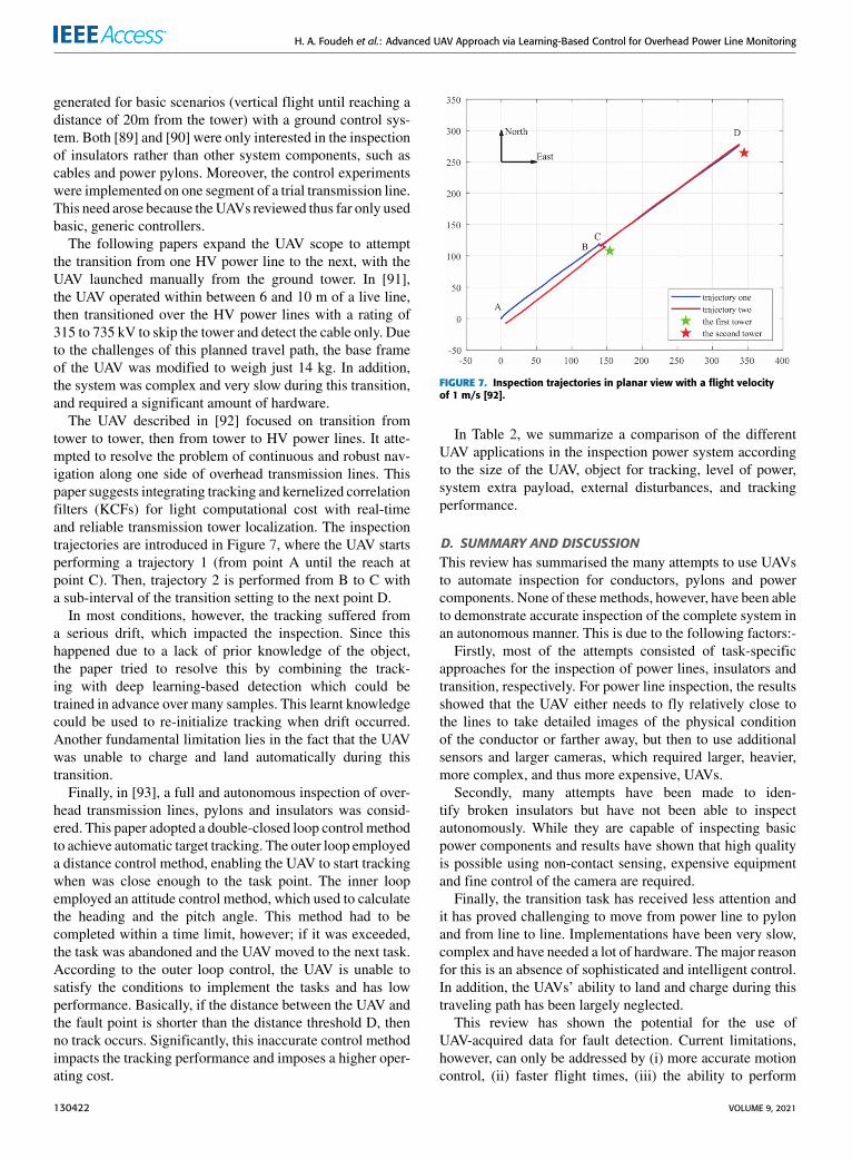
The UAV described in [92] focused on transition fromtower to tower, then from tower to HV power lines. It atte-mpted to resolve the problem of continuous and robust nav-igation along one side of overhead transmission lines. Thispaper suggests integrating tracking and kernelized correlationfilters (KCFs) for light computational cost with real-timeand reliable transmission tower localization. The inspectiontrajectories are introduced in Figure 7, where the UAV startsperforming a trajectory 1 (from point A until the reach atpoint C). Then, trajectory 2 is performed from B to C witha sub-interval of the transition setting to the next point D.
In most conditions, however, the tracking suffered froma serious drift, which impacted the inspection. Since thishappened due to a lack of prior knowledge of the object,the paper tried to resolve this by combining the track-ing with deep learning-based detection which could betrained in advance over many samples. This learnt knowledgecould be used to re-initialize tracking when drift occurred.Another fundamental limitation lies in the fact that the UAVwas unable to charge and land automatically during thistransition.
Finally, in [93], a full and autonomous inspection of over-head transmission lines, pylons and insulators was consid-ered. This paper adopted a double-closed loop control methodto achieve automatic target tracking. The outer loop employeda distance control method, enabling the UAV to start trackingwhen was close enough to the task point. The inner loopemployed an attitude control method, which used to calculatethe heading and the pitch angle. This method had to becompleted within a time limit, however; if it was exceeded,the task was abandoned and the UAV moved to the next task.According to the outer loop control, the UAV is unable tosatisfy the conditions to implement the tasks and has lowperformance. Basically, if the distance between the UAV andthe fault point is shorter than the distance threshold D, thenno track occurs. Significantly, this inaccurate control methodimpacts the tracking performance and imposes a higher oper-ating cost.
FIGURE 7. Inspection trajectories in planar view with a flight velocityof 1 m/s [92].
In Table 2, we summarize a comparison of the differentUAV applications in the inspection power system accordingto the size of the UAV, object for tracking, level of power,system extra payload, external disturbances, and trackingperformance.
D. SUMMARY AND DISCUSSIONThis review has summarised the many attempts to use UAVsto automate inspection for conductors, pylons and powercomponents. None of thesemethods, however, have been ableto demonstrate accurate inspection of the complete system inan autonomous manner. This is due to the following factors:-
Firstly, most of the attempts consisted of task-specificapproaches for the inspection of power lines, insulators andtransition, respectively. For power line inspection, the resultsshowed that the UAV either needs to fly relatively close tothe lines to take detailed images of the physical conditionof the conductor or farther away, but then to use additionalsensors and larger cameras, which required larger, heavier,more complex, and thus more expensive, UAVs.
Secondly, many attempts have been made to iden-tify broken insulators but have not been able to inspectautonomously. While they are capable of inspecting basicpower components and results have shown that high qualityis possible using non-contact sensing, expensive equipmentand fine control of the camera are required.
Finally, the transition task has received less attention andit has proved challenging to move from power line to pylonand from line to line. Implementations have been very slow,complex and have needed a lot of hardware. Themajor reasonfor this is an absence of sophisticated and intelligent control.In addition, the UAVs’ ability to land and charge during thistraveling path has been largely neglected.
This review has shown the potential for the use ofUAV-acquired data for fault detection. Current limitations,however, can only be addressed by (i) more accurate motioncontrol, (ii) faster flight times, (iii) the ability to perform
130422 VOLUME 9, 2021

H. A. Foudeh et al.: Advanced UAV Approach via Learning-Based Control for Overhead Power Line Monitoring
TABLE 3. Comparison of different UAV tracking controls in detecting power system.
automatic transition tasks, (iv) the acquisition of data frommore than one type of sensor and (v) the ability to charge andland automatically. To address the existing limitations of cur-rent UAV-based inspection for HV systems, the next sectionwill review the applications of UAVs in data collection thathas potential to address the pressing problems outlined above.
Since this is a challenging task, it will require moreadvanced controllers than currently exist. In particular, sincethe inspection is inherently repetitive, this motivates thedevelopment of Iterative Learning Control (ILC) based algo-rithms for high performance tracking.
IV. ITERATIVE LEARNING CONTROL IN UAVAPPLICATIONSThe iterative learning control concept refers to the repeata-bility of operating a given objective and the possibility ofimproving the control input over previous operations (i.e. tri-als, iterations, and passes) through learning. In addition, ILCis an approach to improving the transient response perfor-mance of the system, which runs frequently over a specifiedperiod of time until accurate tracking is achieved. Moreover,the ILC approach is usually called recursive online con-trol because it (i) requires less calculation and (ii) requiresless prior knowledge about the system dynamics. In the last20 years, iterative learning control has continued to evolve ata fast pace, especially in quadrotor applications.
Their application was motivated by the proven inherentadvantages of past work, which include increased accuracyand robustness in case of uncertainties and external distur-bances. The following sections describe the significant poten-tial of iterative learning control in UAVs applications, and canbe grouped in three categories, starting with basic ILC forms,then ILC in combination with different control approaches.Finally, UAVs to achieve high performance with the moregeneral ILC forms available are described, with a focus onthose that have been applied in practice to engineering sys-tems, which bears a particular focus in this paper.
Iterative learning control was first proposed in 1978 byUchiyama [129], however, as this paper was written inJapanese, it did not receive significant attention outsideJapan. In 1984, Arimoto proposed the first learning algorithmand ILC has since been applied to many fields, includingrobotics [130]. This defines ILC as a novel control techniqueapplicable to systems operating in a repetitive manner overa finite time interval, which may be denoted as [0,T ]. Sincethen, a mature framework has been built up for the develop-ment and analysis of linear ILC. The Figure 8 illustrates thegeneral block diagram of an iterative learning scheme. Here kis the trial number and the object is an updated input uk suchthat lim
k→∞ek = 0.
FIGURE 8. General block diagram of D-type-ILC based controller [135].
In [131] a basic ILC form was applied to a quadro-tor to obtain increased performance through learning. Theemphasis was on performing some fundamental missionsfor a quadrotor through simulations for different missions.In order to control the quadrotor, three different methods wereapplied: off-line ILC, on-line ILC, and a combination of bothon-line and off-line ILC. These have the respective forms
uk+1(t) = uk (t)+ KPek (t)︸ ︷︷ ︸offline P-type
, (2)
uk+1(t) = uk (t)+ KPek+1(t)︸ ︷︷ ︸online P-type
, (3)
VOLUME 9, 2021 130423

H. A. Foudeh et al.: Advanced UAV Approach via Learning-Based Control for Overhead Power Line Monitoring
The authors designed an on-line ILC update for quadrotortrajectory tracking control, employing an inner proportional-derivative (PD) controller in order to stabilize the systemgiven by
uk+1(t)=uk (t)+ kpek (t + 1)+ kd [ek (t + 1)− ek (t)] (4)
where t indicates the sample number in discrete time. Thesystem showed large tracking errors but ILC was able toreduce it in subsequent iterations.
Another study was conducted in [132] and implementedthe same basic ILC of [131] with an adaptive componentto enhance the controller performance and robustness. Thiswas applied to a quadrotor and experimental results showedgood tracking performance in the presence of disturbances.However, both [131], [132] used the basic PD-type ILC formand could not ensure monotonic convergence, which meansthat the average error may increase throughout iterations as kincreases.
Similarly to [131] and [132], the authors in [133] alsodeveloped a PID controller based on basic ILC form tooptimize the travel path; this provides a controllable flightin various environmental conditions, especially after chang-ing the total mass of the UAV (by adding extra load). Thedifference is that the parameters were tuning manually andno practical experiment has been done in [131] and [132],while real-time auto-tuning method for parameters based onthe basic ILC form was considered in [133]. The next groupof references will focus on ILC in combination with differentcontrol approaches.
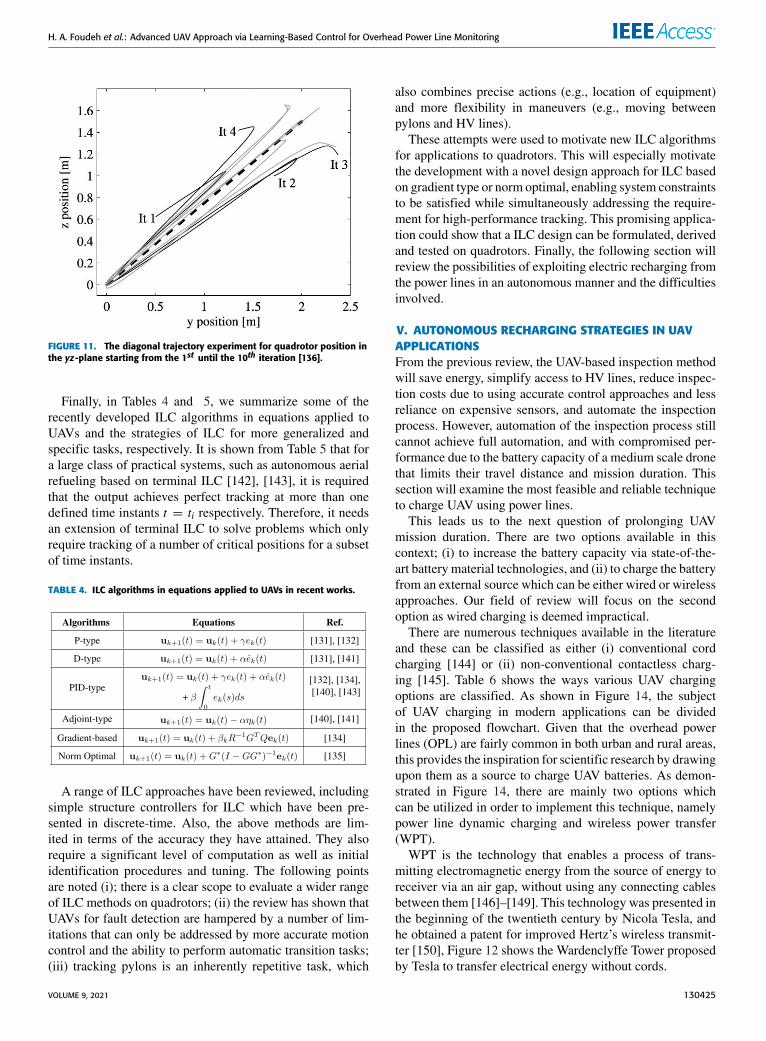
The above basic ILC strategies were all based on theassumption that the ILC requires a tuning gain matrix andin one case a delay-time constant, and do not require anexplicit model. This simplicity aids usability but necessar-ily degrades performance. Thus in [134], [135] and [136],optimization based ILC approaches are used to address theselimitations. In [134] and [135], the performance of ILCin gradient-based that enhances a quadrotor’s controllabil-ity and stability during attitude control is examined. Againin [136], the optimization based ILC approach was appliedto achieve quadrotor trajectory tracking while balancing aninverted pendulum. Figure 9 presents the image sequence ofapplication of ILC to a quadrotor by tracking a small trajec-tory indoors and the convergence of ILC when applied to aquadrotor.
The experiments in [134], [135] and [136] showed the fastrate of convergence of the norm error which is low after asmall number of trials, although in some cases the method isslow as illustrated in Figures 10 and 11. It was shown that bothstudies outperformed the strategy proposed in [130]–[132] interms of convergence speed, trajectory tracking performanceand robustness. One shortcoming of this strategy is that itneglects the impact of non-repetitive noise on the systemoutput.
Other attempts to address the disturbance using the ILCin combination with different control approaches have beenconducted in [137], [138]. In [139], the authors designed a
FIGURE 9. 1st iteration to 4th Iteration of ILC based trajectory tracking.
FIGURE 10. Optimized error convergence rate with a variation on thelearning gain β values [135].
Back-stepping Integral Sliding Mode Control (BISMC) withILC algorithm for a quadrotor. The back-stepping is responsi-ble for tracking the desired trajectory, then the integral slidingmode controller is designed and analyzed for coping withthe uncertainties and external disturbances. Finally, iterativelearning control is designed to improve the accuracy of thetracking. Meanwhile [138] introduced a design based on thecapabilities of L1 adaptive control combined with ILC toachieve high-precision trajectory tracking in the presence ofunknown and changing disturbances.
The two approaches [137], [138] are similar in terms ofusing the same basic ILC; the addition of which improves theaccuracy. However, the constraint described in [138], that thebackstepping relies heavily on the dynamics of the system,that the system is not given in strict feedback form for boththe attitude angles, and the integral sliding mode controllerhas chattering phenomena all limit its application. Moreover,the main challenge facing the approach in [138] is the trainingof the UAV to operate in changing environments, which isboth complex and time-consuming in terms of both designlife cycle and computational intensity.
130424 VOLUME 9, 2021
H. A. Foudeh et al.: Advanced UAV Approach via Learning-Based Control for Overhead Power Line Monitoring
FIGURE 11. The diagonal trajectory experiment for quadrotor position inthe yz-plane starting from the 1st until the 10th iteration [136].
Finally, in Tables 4 and 5, we summarize some of therecently developed ILC algorithms in equations applied toUAVs and the strategies of ILC for more generalized andspecific tasks, respectively. It is shown from Table 5 that fora large class of practical systems, such as autonomous aerialrefueling based on terminal ILC [142], [143], it is requiredthat the output achieves perfect tracking at more than onedefined time instants t = ti respectively. Therefore, it needsan extension of terminal ILC to solve problems which onlyrequire tracking of a number of critical positions for a subsetof time instants.
TABLE 4. ILC algorithms in equations applied to UAVs in recent works.
A range of ILC approaches have been reviewed, includingsimple structure controllers for ILC which have been pre-sented in discrete-time. Also, the above methods are lim-ited in terms of the accuracy they have attained. They alsorequire a significant level of computation as well as initialidentification procedures and tuning. The following pointsare noted (i); there is a clear scope to evaluate a wider rangeof ILC methods on quadrotors; (ii) the review has shown thatUAVs for fault detection are hampered by a number of lim-itations that can only be addressed by more accurate motioncontrol and the ability to perform automatic transition tasks;(iii) tracking pylons is an inherently repetitive task, which
also combines precise actions (e.g., location of equipment)and more flexibility in maneuvers (e.g., moving betweenpylons and HV lines).
These attempts were used to motivate new ILC algorithmsfor applications to quadrotors. This will especially motivatethe development with a novel design approach for ILC basedon gradient type or norm optimal, enabling system constraintsto be satisfied while simultaneously addressing the require-ment for high-performance tracking. This promising applica-tion could show that a ILC design can be formulated, derivedand tested on quadrotors. Finally, the following section willreview the possibilities of exploiting electric recharging fromthe power lines in an autonomous manner and the difficultiesinvolved.
V. AUTONOMOUS RECHARGING STRATEGIES IN UAVAPPLICATIONSFrom the previous review, the UAV-based inspection methodwill save energy, simplify access to HV lines, reduce inspec-tion costs due to using accurate control approaches and lessreliance on expensive sensors, and automate the inspectionprocess. However, automation of the inspection process stillcannot achieve full automation, and with compromised per-formance due to the battery capacity of a medium scale dronethat limits their travel distance and mission duration. Thissection will examine the most feasible and reliable techniqueto charge UAV using power lines.
This leads us to the next question of prolonging UAVmission duration. There are two options available in thiscontext; (i) to increase the battery capacity via state-of-the-art battery material technologies, and (ii) to charge the batteryfrom an external source which can be either wired or wirelessapproaches. Our field of review will focus on the secondoption as wired charging is deemed impractical.
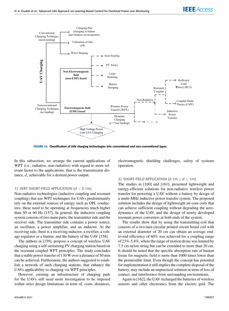
There are numerous techniques available in the literatureand these can be classified as either (i) conventional cordcharging [144] or (ii) non-conventional contactless charg-ing [145]. Table 6 shows the ways various UAV chargingoptions are classified. As shown in Figure 14, the subjectof UAV charging in modern applications can be dividedin the proposed flowchart. Given that the overhead powerlines (OPL) are fairly common in both urban and rural areas,this provides the inspiration for scientific research by drawingupon them as a source to charge UAV batteries. As demon-strated in Figure 14, there are mainly two options whichcan be utilized in order to implement this technique, namelypower line dynamic charging and wireless power transfer(WPT).
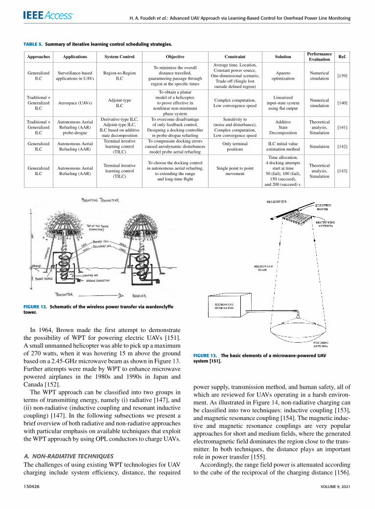
WPT is the technology that enables a process of trans-mitting electromagnetic energy from the source of energy toreceiver via an air gap, without using any connecting cablesbetween them [146]–[149]. This technology was presented inthe beginning of the twentieth century by Nicola Tesla, andhe obtained a patent for improved Hertz’s wireless transmit-ter [150], Figure 12 shows the Wardenclyffe Tower proposedby Tesla to transfer electrical energy without cords.
VOLUME 9, 2021 130425
H. A. Foudeh et al.: Advanced UAV Approach via Learning-Based Control for Overhead Power Line Monitoring
TABLE 5. Summary of iterative learning control scheduling strategies.
FIGURE 12. Schematic of the wireless power transfer via wardenclyffetower.
In 1964, Brown made the first attempt to demonstratethe possibility of WPT for powering electric UAVs [151].A small unmanned helicopter was able to pick up a maximumof 270 watts, when it was hovering 15 m above the groundbased on a 2.45-GHzmicrowave beam as shown in Figure 13.Further attempts were made by WPT to enhance microwavepowered airplanes in the 1980s and 1990s in Japan andCanada [152].
The WPT approach can be classified into two groups interms of transmitting energy, namely (i) radiative [147], and(ii) non-radiative (inductive coupling and resonant inductivecoupling) [147]. In the following subsections we present abrief overview of both radiative and non-radiative approacheswith particular emphasis on available techniques that exploittheWPT approach by using OPL conductors to charge UAVs.
A. NON-RADIATIVE TECHNIQUESThe challenges of using existing WPT technologies for UAVcharging include system efficiency, distance, the required
FIGURE 13. The basic elements of a microwave-powered UAVsystem [151].
power supply, transmission method, and human safety, all ofwhich are reviewed for UAVs operating in a harsh environ-ment. As illustrated in Figure 14, non-radiative charging canbe classified into two techniques: inductive coupling [153],and magnetic resonance coupling [154]. The magnetic induc-tive and magnetic resonance couplings are very popularapproaches for short and medium fields, where the generatedelectromagnetic field dominates the region close to the trans-mitter. In both techniques, the distance plays an importantrole in power transfer [155].
Accordingly, the range field power is attenuated accordingto the cube of the reciprocal of the charging distance [156].
130426 VOLUME 9, 2021
H. A. Foudeh et al.: Advanced UAV Approach via Learning-Based Control for Overhead Power Line Monitoring
FIGURE 14. Classification of UAV charging technologies into conventional and non-conventional types.
In this subsection, we arrange the current applications ofWPT (i.e., radiative, non-radiative) with regard to more rel-evant factor to the applications, that is the transmission dis-tance, d , achievable for a desired power output.
1) VERY SHORT-FIELD APPLICATION (d < 0.1m)Non-radiative technologies (inductive coupling and resonantcoupling) that use WPT techniques for UAVs predominantlyrely on the external sources of energy such as OPL conduc-tors; these need to be operating at frequencies much higherthan 50 or 60 Hz [157]. In general, the inductive couplingsystem consists of twomain parts; the transmitter side and thereceiver side. The transmitter side contains a power source,an oscillator, a power amplifier, and an inductor. At thereceiving side, there is a receiving inductor, a rectifier, a volt-age regulator or a limiter, and the battery of the UAV [158].
The authors in [159], propose a concept of wireless UAVcharging using a self-sustaining PV charging station based onthe resonant coupled WPT principles. The study concludesthat a stable power transfer of 130Wover a distance of 50mmcan be achieved. Furthermore, the authors suggested to estab-lish a network of such charging stations, that enhance theUAVs applicability to charging via WPT principles.
However, creating an infrastructure of charging padsfor the UAVs still need more investigation to be imposedwithin strict design limitations in term of, costs, distances,
electromagnetic shielding challenges, safety of systemsoperation.
2) SHORT-FIELD APPLICATION (0.1m ≤ d ≤ 1m)The studies in [160] and [161], presented lightweight andenergy-efficient solutions for non-radiative wireless powertransfer for powering a UAV without a battery by design ofa multi-MHz inductive power transfer system. The proposedsolution includes the design of lightweight air-core coils thatcan achieve sufficient coupling without degrading the aero-dynamics of the UAV, and the design of newly developedresonant power converters at both ends of the system.
The results show that by using the transmitting-coil thatconsists of a two-turn circular printed circuit board coil withan external diameter of 20 cm can obtain an average end-to-end efficiency of 60% was achieved for a coupling rangeof 23%-5.8%,where the range ofmotion dronewas limited by7.5 cm nylon string but can be extended to more than 20 cm.It should be noted that the specific absorption rate of humantissue for magnetic field is more than 1000 times lower thanthe permissible limit. Even though the concept has potentialfor implementation it still implies the complete disposal of thebattery, may include an impractical solution in term of loss ofcontact, and interference from surrounding environments.
Again in [162], the UAV recharged the batteries of wirelesssensors and other electronics from the electric grid. The
VOLUME 9, 2021 130427
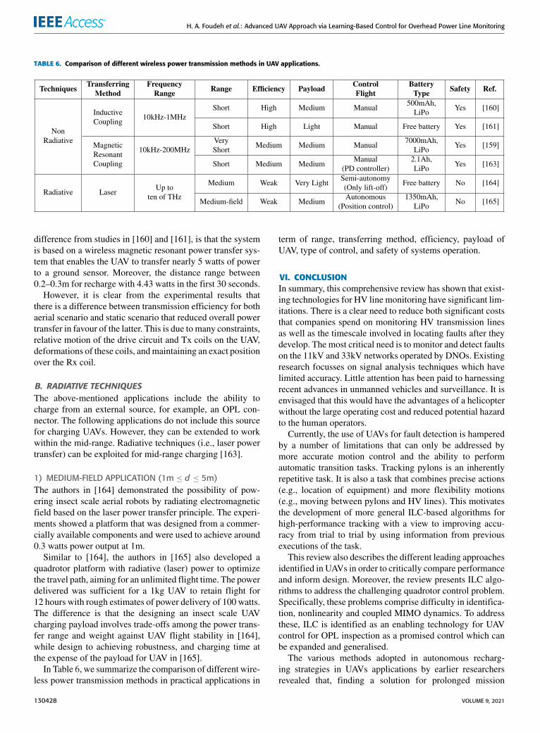
H. A. Foudeh et al.: Advanced UAV Approach via Learning-Based Control for Overhead Power Line Monitoring
TABLE 6. Comparison of different wireless power transmission methods in UAV applications.
difference from studies in [160] and [161], is that the systemis based on a wireless magnetic resonant power transfer sys-tem that enables the UAV to transfer nearly 5 watts of powerto a ground sensor. Moreover, the distance range between0.2–0.3m for recharge with 4.43 watts in the first 30 seconds.
However, it is clear from the experimental results thatthere is a difference between transmission efficiency for bothaerial scenario and static scenario that reduced overall powertransfer in favour of the latter. This is due to many constraints,relative motion of the drive circuit and Tx coils on the UAV,deformations of these coils, andmaintaining an exact positionover the Rx coil.
B. RADIATIVE TECHNIQUESThe above-mentioned applications include the ability tocharge from an external source, for example, an OPL con-nector. The following applications do not include this sourcefor charging UAVs. However, they can be extended to workwithin the mid-range. Radiative techniques (i.e., laser powertransfer) can be exploited for mid-range charging [163].
1) MEDIUM-FIELD APPLICATION (1m ≤ d ≤ 5m)The authors in [164] demonstrated the possibility of pow-ering insect scale aerial robots by radiating electromagneticfield based on the laser power transfer principle. The experi-ments showed a platform that was designed from a commer-cially available components and were used to achieve around0.3 watts power output at 1m.
Similar to [164], the authors in [165] also developed aquadrotor platform with radiative (laser) power to optimizethe travel path, aiming for an unlimited flight time. The powerdelivered was sufficient for a 1kg UAV to retain flight for12 hours with rough estimates of power delivery of 100 watts.The difference is that the designing an insect scale UAVcharging payload involves trade-offs among the power trans-fer range and weight against UAV flight stability in [164],while design to achieving robustness, and charging time atthe expense of the payload for UAV in [165].
In Table 6, we summarize the comparison of different wire-less power transmission methods in practical applications in
term of range, transferring method, efficiency, payload ofUAV, type of control, and safety of systems operation.
VI. CONCLUSIONIn summary, this comprehensive review has shown that exist-ing technologies for HV line monitoring have significant lim-itations. There is a clear need to reduce both significant coststhat companies spend on monitoring HV transmission linesas well as the timescale involved in locating faults after theydevelop. The most critical need is to monitor and detect faultson the 11kV and 33kV networks operated by DNOs. Existingresearch focusses on signal analysis techniques which havelimited accuracy. Little attention has been paid to harnessingrecent advances in unmanned vehicles and surveillance. It isenvisaged that this would have the advantages of a helicopterwithout the large operating cost and reduced potential hazardto the human operators.
Currently, the use of UAVs for fault detection is hamperedby a number of limitations that can only be addressed bymore accurate motion control and the ability to performautomatic transition tasks. Tracking pylons is an inherentlyrepetitive task. It is also a task that combines precise actions(e.g., location of equipment) and more flexibility motions(e.g., moving between pylons and HV lines). This motivatesthe development of more general ILC-based algorithms forhigh-performance tracking with a view to improving accu-racy from trial to trial by using information from previousexecutions of the task.
This review also describes the different leading approachesidentified in UAVs in order to critically compare performanceand inform design. Moreover, the review presents ILC algo-rithms to address the challenging quadrotor control problem.Specifically, these problems comprise difficulty in identifica-tion, nonlinearity and coupled MIMO dynamics. To addressthese, ILC is identified as an enabling technology for UAVcontrol for OPL inspection as a promised control which canbe expanded and generalised.
The various methods adopted in autonomous recharg-ing strategies in UAVs applications by earlier researchersrevealed that, finding a solution for prolonged mission
130428 VOLUME 9, 2021
H. A. Foudeh et al.: Advanced UAV Approach via Learning-Based Control for Overhead Power Line Monitoring
duration is a complex task, particularly when charge thebattery from an external source (OPL conductors). The funda-mental conflict between accuracy, efficiency, reliability, andhuman safety is always present in these types of problems.A trade-off has to be made with these methods to arrive at thesolution for autonomous recharging strategies that satisfy theconstraints.
Generally, there are two issues to be considered in thedesign of recharging UAVs dispatch:
1) Given the fact that standard overhead power line fre-quencies utilized in the industry are 50 or 60 Hz, it isnecessary to process a frequency conversion due tothe operating range for method (i.e., magnetic resonantcoupling) that lies in the kHz to MHz region.
2) Given that the frequency conversion process is nec-essary in WPT techniques, there are two options fordesigning the permissible weight of WPT conversionequipment; (i) overhead power line, and (ii) on-boardthe UAV. The former is limited in terms of the elec-tromagnetic interference, shielding, and infrastructuralmaintenance. The latter instead is restricted by the UAVframe and payload.
Finally, as the world changes in light of the COVID-19outbreak, it is also time for effective and proportionate changein these new circumstances. Moreover, integration of techno-logical solutions such as UAVs in the power system will havea profound impact on mitigating the impact of COVID-19.Since it is a technology that does not depend on socialcommunication and are restricted by the non-contact sensingtechnologies.
ACKNOWLEDGMENTThe authors confirm that the data supporting the findings ofthis study are available within the article.
REFERENCES[1] P. Dehghanian, S. Aslan, and P. Dehghanian, ‘‘Maintaining electric sys-
tem safety through an enhanced network resilience,’’ IEEE Trans. Ind.Appl., vol. 54, no. 5, pp. 4927–4937, Sep. 2018.
[2] R. Schwarz, T. Judendorfer, and M. Muhr, ‘‘Review of partial dischargemonitoring techniques used in high voltage equipment,’’ in Proc. Annu.Rep. Conf. Electr. Insul. Dielectr. Phenomena, Oct. 2008, pp. 400–403.
[3] V. I. Kogan and R. J. Gursky, ‘‘Transmission towers inventory,’’ IEEETrans. Power Del., vol. 11, no. 4, pp. 1842–1852, Oct. 1996.
[4] A. Moradkhani, M. R. Haghifam, and M. Mohammadzadeh, ‘‘Failurerate modelling of electric distribution overhead lines considering pre-ventive maintenance,’’ IET Gener., Transmiss. Distrib., vol. 8, no. 6,pp. 1028–1038, Jun. 2014.
[5] R. Shariatinasab, F. Ajri, and H. Daman-Khorshid, ‘‘Probabilistic evalu-ation of failure risk of transmission line surge arresters caused by light-ning flash,’’ IET Gener., Transmiss. Distrib., vol. 8, no. 2, pp. 193–202,Feb. 2014.
[6] P. Dehghanian and S. Aslan, ‘‘Enhancing electric safety by improvingsystem resiliency in face of extreme emergencies,’’ in Proc. IEEE IASElectr. Saf. Workshop (ESW), Feb. 2017, p. 1.
[7] D. A. Reed, ‘‘Electric utility distribution analysis for extreme winds,’’J. Wind Eng. Ind. Aerodyn., vol. 96, no. 1, pp. 123–140, Jan. 2008.
[8] E. H. Allen, R. B. Stuart, and T. E. Wiedman, ‘‘No light in August: Powersystem restoration following the 2003 North American blackout,’’ IEEEPower Energy Mag., vol. 12, no. 1, pp. 24–33, Jan. 2014.
[9] H. J. Na and S. Yoo, ‘‘PSO-based dynamic UAV positioning algorithmfor sensing information acquisition in wireless sensor networks,’’ IEEEAccess, vol. 7, pp. 77499–77513, Jun. 2019.
[10] N. Gageik, P. Benz, and S. Montenegro, ‘‘Obstacle detection and colli-sion avoidance for a UAV with complementary low-cost sensors,’’ IEEEAccess, vol. 3, pp. 599–609, May 2015.
[11] E. Davis and P. E. I. Pounds, ‘‘Direct sensing of thrust and velocityfor a quadrotor rotor array,’’ IEEE Robot. Autom. Lett., vol. 2, no. 3,pp. 1360–1366, Jul. 2017.
[12] V. N. Nguyen, R. Jenssen, and D. Roverso, ‘‘Intelligent monitoringand inspection of power line components powered by UAVs and deeplearning,’’ IEEE Power Energy Technol. Syst. J., vol. 6, no. 1, pp. 11–21,Mar. 2019.
[13] J. Katrasnik, F. Pernus, and B. Likar, ‘‘A survey of mobile robots fordistribution power line inspection,’’ IEEE Trans. Power Del., vol. 25,no. 1, pp. 485–493, Jan. 2010.
[14] J. Sawada, K. Kusumoto, Y. Maikawa, T. Munakata, and Y. Ishikawa,‘‘Amobile robot for inspection of power transmission lines,’’ IEEE Trans.Power Del., vol. 6, no. 1, pp. 309–315, Jan. 1991.
[15] L. Matikainen, M. Lehtomäki, E. Ahokas, J. Hyyppä, M. Karjalainen,A. Jaakkola, A. Kukko, and T. Heinonen, ‘‘Remote sensing methodsfor power line corridor surveys,’’ ISPRS J. Photogramm. Remote Sens.,vol. 119, pp. 10–31, Sep. 2016.
[16] V. N. Nguyen, R. Jenssen, and D. Roverso, ‘‘Automatic autonomousvision-based power line inspection: A review of current status and thepotential role of deep learning,’’ Int. J. Electr. Power Energy Syst., vol. 99,pp. 107–120, Jul. 2018.
[17] Q. Huang, W. Zhen, and P. W. T. Pong, ‘‘A novel approach for faultlocation of overhead transmission line with noncontact magnetic-fieldmeasurement,’’ IEEE Trans. Power Del., vol. 27, no. 3, pp. 1186–1195,Jul. 2012.
[18] B. Yang, V. Vittal, and G. T. Heydt, ‘‘Slow-coherency-based con-trolled islanding—A demonstration of the approach on the August 14,2003 blackout scenario,’’ IEEE Trans. Power Syst., vol. 21, no. 4,pp. 1840–1847, Nov. 2006.
[19] Final Report on the August 14, 2003 Blackout in the United States andCanada: Causes and Recommendations, U.S. Canada Power Syst. OutageTask Force, Washington, DC, USA, Apr. 2004.
[20] J. E. Chadwick, ‘‘How a smarter grid could have prevented the 2003 U.S.cascading blackout,’’ in Proc. IEEE Power Energy Conf. Illinois (PECI),Feb. 2013, pp. 65–71.
[21] H. Foudeh and A. S. Mokhtar, ‘‘Elimination of total harmonic distortionin transmission lines using adaptive fuzzy logic in de-icing process,’’ inProc. 9th Jordanian Int. Electr. Electron. Eng. Conf. (JIEEEC), Oct. 2015,pp. 1–6.
[22] L. Martin, ‘‘Transmission structure risk management,’’ IEEE PowerEnergy Mag., vol. 14, no. 5, pp. 28–33, Sep. 2016.
[23] L. Li, ‘‘A review of techniques to detect downed conductors in overheaddistribution systems,’’ in Proc. 7th Int. Conf. Develop. Power Syst. Pro-tection (DPSP), Apr. 2001, pp. 169–172.
[24] L. E. Kollar and M. Farzaneh, ‘‘Vibration of bundled conductors follow-ing ice shedding,’’ IEEE Trans. Power Del., vol. 23, no. 2, pp. 1097–1104,Apr. 2008.
[25] R. Benato and D. Napolitano, ‘‘Overall cost comparison between cableand overhead lines including the costs for repair after random failures,’’IEEE Trans. Power Del., vol. 27, no. 3, pp. 1213–1222, Jul. 2012.
[26] L. E. Kollar, M. Farzaneh, and P. Van Dyke, ‘‘Modeling ice sheddingpropagation on transmission lines with or without interphase spacers,’’IEEE Trans. Power Del., vol. 28, no. 1, pp. 261–267, Jan. 2013.
[27] T. Sonoda, H. Morii, and S. Sekioka, ‘‘Observation of lightning overvolt-age in a 500 kV switching station,’’ IEEE Trans. PowerDel., vol. 32, no. 4,pp. 1828–1834, Aug. 2017.
[28] D. Zaninelli and A. Ballocchi, ‘‘Fault analysis on AC/HV cable trans-mission lines,’’ IEEE Trans. Power Del., vol. 15, no. 2, pp. 616–622,Apr. 2000.
[29] R. H. Salim, M. Resener, A. D. Filomena, K. R. C. D. Oliveira, andA. S. Bretas, ‘‘Extended fault-location formulation for power distributionsystems,’’ IEEE Trans. PowerDel., vol. 24, no. 2, pp. 508–516, Apr. 2009.
[30] O. A. S. Youssef, ‘‘Combined fuzzy-logic wavelet-based fault classifi-cation technique for power system relaying,’’ IEEE Trans. Power Del.,vol. 19, no. 2, pp. 582–589, Apr. 2004.
[31] S. R. Samantaray, ‘‘Decision tree-based fault zone identification and faultclassification in flexible AC transmissions-based transmission line,’’ IETGener., Transmiss. Distrib., vol. 3, no. 5, pp. 425–436, May 2009.
VOLUME 9, 2021 130429
H. A. Foudeh et al.: Advanced UAV Approach via Learning-Based Control for Overhead Power Line Monitoring
[32] C. S. Mardegan and R. Rifaat, ‘‘Insights into applications of IEEE stan-dards for ground-fault protection in industrial and commercial powersystems,’’ IEEE Trans. Ind. Appl., vol. 51, no. 4, pp. 2854–2861,Jul./Aug. 2015.
[33] L. Shang and J. Lv, ‘‘A new approach for identification of the fault typeon transmission lines,’’ in Proc. 2nd Int. Conf. Syst. Informat. (ICSAI),Nov. 2014, pp. 132–136.
[34] G. C. Silva, F. Piazza, and M. Munaro, ‘‘Field behavior on polymer-covered overhead conductors submitted to natural aging on diverseweather and geographic conditions in Brazil,’’ IEEE Trans. Power Del.,vol. 24, no. 3, pp. 1651–1656, Jul. 2009.
[35] X. Qin, G. Wu, J. Lei, F. Fan, X. Ye, and Q. Mei, ‘‘A novel method ofautonomous inspection for transmission line based on cable inspectionrobot LiDAR data,’’ Sensors, vol. 18, no. 2, Feb. 2018, Art. no. 596.
[36] F. Yeves and P. M. Martinez, ‘‘Helicopter operator qualifications for linework,’’ IEEE Trans. Power Del., vol. 15, no. 1, pp. 326–332, Jan. 2000.
[37] C. C. Whitworth, A. W. G. Duller, D. I. Jones, and G. K. Earp, ‘‘Aerialvideo inspection of overhead power lines,’’ Power Eng. J., vol. 15, no. 1,pp. 25–32, Feb. 2001.
[38] IEEE Task Force 15.07.05.05, ‘‘Recommended practices for helicopterbonding procedures for live-line work,’’ IEEE Trans. Power Del., vol. 15,no. 1, pp. 333–349, Jan. 2000.
[39] H.Manninen, J. Kilter, andM. Landsberg, ‘‘Advanced condition monitor-ing method for high voltage overhead lines based on visual inspection,’’in Proc. IEEE Power Energy Soc. Gen. Meeting (PESGM), Aug. 2018,pp. 1–5.
[40] M. de Nigris, I. Gutman, and A. Pigini, ‘‘Live-line maintenance of ACoverhead lines equipped with non ceramic insulators (NCI),’’ in Proc.IEEE PES Transmiss. Distrib. Conf. Expo., Apr. 2010, pp. 1–6.
[41] M. Yokoya, Y. Katsuragi, Y. Goda, Y. Nagata, and Y. Asano, ‘‘Develop-ment of lightning-resistant overhead ground wire,’’ IEEE Trans. PowerDel., vol. 9, no. 3, pp. 1517–1523, Jul. 1994.
[42] X. Qin, G. Wu, J. Lei, F. Fan, and X. Ye, ‘‘Detecting inspection objectsof power line from cable inspection robot LiDAR data,’’ Sensors, vol. 18,no. 4, Apr. 2018, Art. no. 1284.
[43] M. Ghassemi, M. Farzaneh, and W. A. Chisholm, ‘‘Three-dimensionalFEM electrical field calculation for FRP hot stick during EHV live-linework,’’ IEEE Trans. Dielectr. Electr. Insul., vol. 21, no. 6, pp. 2531–2540,Dec. 2014.
[44] Y. Zhai, R. Chen, Q. Yang, X. Li, and Z. Zhao, ‘‘Insulator fault detectionbased on spatial morphological features of aerial images,’’ IEEE Access,vol. 6, pp. 35316–35326, Jun. 2018.
[45] G. H. Vaillancourt, S. Carignan, and C. Jean, ‘‘Experience with thedetection of faulty composite insulators on high-voltage power lines bythe electric field measurement method,’’ IEEE Trans. Power Del., vol. 13,no. 2, pp. 661–666, Apr. 1998.
[46] S. Han, R. Hao, and J. Lee, ‘‘Inspection of insulators on high-voltagepower transmission lines,’’ IEEE Trans. Power Del., vol. 24, no. 4,pp. 2319–2327, Oct. 2009.
[47] O. Menendez, F. A. A. Cheein, M. Perez, and S. Kouro, ‘‘Roboticsin power systems: Enabling a more reliable and safe grid,’’ IEEE Ind.Electron. Mag., vol. 11, no. 2, pp. 22–34, Jun. 2017.
[48] V. T. Morgan, ‘‘The detection and damping of overhead-line conductorvibration,’’ Proc. IEE A, Power Eng., vol. 109, no. 3, pp. 239–250, 1962.
[49] A. Leblond and K. E. Lindsey, ‘‘Maintenance,’’ in Overhead Lines(CIGRE Green Books), K. O. Papailiou, Ed. Cham, Switzerland:Springer, 2017, pp. 1151–1208.
[50] M. Nayyerloo, X. Chen, W. Wang, and J. G. Chase, ‘‘Cable-climbingrobots for power line inspection,’’ in Mobile Robots: State of the Art inLand, Sea, Air, and Collaborative Missions, X. Chen, Ed. Rijeka, Croatia:InTech, 2009.
[51] S. D. Guikema, R. A. Davidson, and H. Liu, ‘‘Statistical models of theeffects of tree trimming on power system outages,’’ IEEE Trans. PowerDel., vol. 21, no. 3, pp. 1549–1557, Jul. 2006.
[52] T. Dokic and M. Kezunovic, ‘‘Predictive risk management for dynamictree trimming scheduling for distribution networks,’’ IEEE Trans. SmartGrid, vol. 10, no. 5, pp. 4776–4785, Sep. 2019.
[53] ESMOL Subcommittee, ‘‘Safety considerations when placing a personwith tools in an air gap to change porcelain and glass insulators ontransmission systems of 345 kV and above, using ladder and aerial liftmethods,’’ IEEE Trans. Power Del., vol. 17, no. 3, pp. 805–808, Jul. 2002.
[54] J. Stewart, ‘‘Review of WPD unit costs,’’ Parsons Brinckerhoff,New York, NY, USA, Tech. Rep. 3512700A, 2013.
[55] Z. Zhu, S. Lu, B. Gao, T. Yi, and B. Chen, ‘‘Life cycle cost analysis ofthree types of power lines in 10 kV distribution network,’’ Inventions,vol. 1, no. 4, p. 20, Oct. 2016.
[56] T. S. Kishore and S. K. Singal, ‘‘Optimal economic planning of powertransmission lines: A review,’’ Renew. Sustain. Energy Rev., vol. 39,pp. 949–974, Nov. 2014.
[57] Y. Q. Chen, O. Fink, and G. Sansavini, ‘‘Combined fault location andclassification for power transmission lines fault diagnosis with inte-grated feature extraction,’’ IEEE Trans. Ind. Electron., vol. 65, no. 1,pp. 561–569, Jan. 2018.
[58] A. de Souza Gomes, M. A. Costa, T. G. A. de Faria, andW.M. Caminhas,‘‘Detection and classification of faults in power transmission lines usingfunctional analysis and computational intelligence,’’ IEEE Trans. PowerDel., vol. 28, no. 3, pp. 1402–1413, Jul. 2013.
[59] J. Izykowski, R. Molag, E. Rosolowski, and M. M. Saha, ‘‘Accuratelocation of faults on power transmission lines with use of two-endunsynchronized measurements,’’ IEEE Trans. Power Del., vol. 21, no. 2,pp. 627–633, Apr. 2006.
[60] M. Abad, M. García-Gracia, N. E. Halabi, and D. L. Andía, ‘‘Networkimpulse response based-on fault location method for fault location inpower distribution systems,’’ IET Gener., Transmiss. Distrib., vol. 10,no. 15, pp. 3962–3970, Nov. 2016.
[61] S. S. Gururajapathy, H. Mokhlis, and H. A. Illias, ‘‘Fault location anddetection techniques in power distribution systems with distributed gen-eration: A review,’’ Renew. Sustain. Energy Rev., vol. 74, pp. 949–958,Jul. 2017.
[62] S. F. Alwash, V. K. Ramachandaramurthy, and N. Mithulananthan,‘‘Fault-location scheme for power distribution system with distributedgeneration,’’ IEEE Trans. Power Del., vol. 30, no. 3, pp. 1187–1195,Jun. 2015.
[63] S. Lin, Z. Y. He, X. P. Li, and Q. Q. Qian, ‘‘Travelling wave time–frequency characteristic-based fault location method for transmissionlines,’’ IET Gener., Transmiss. Distrib., vol. 6, no. 8, pp. 764–772,Aug. 2012.
[64] G. Cardoso, J. G. Rolim, and H. H. Zurn, ‘‘Application of neural-networkmodules to electric power system fault section estimation,’’ IEEE Trans.Power Del., vol. 19, no. 3, pp. 1034–1041, Jul. 2004.
[65] B. Ravikumar, D. Thukaram, and H. P. Khincha, ‘‘Application of supportvector machines for fault diagnosis in power transmission system,’’ IETGener., Transmiss. Distrib., vol. 2, no. 1, pp. 119–130, Jan. 2008.
[66] A. K. Pradhan, A. Routray, and B. Biswal, ‘‘Higher order statistics-fuzzy integrated scheme for fault classification of a series-compensatedtransmission line,’’ IEEE Trans. Power Del., vol. 19, no. 2, pp. 891–893,Apr. 2004.
[67] M. T. Sant and Y. G. Paithankar, ‘‘Online digital fault locator foroverhead transmission line,’’ Proc. Inst. Electr. Eng., vol. 126, no. 11,pp. 1181–1185, Nov. 1979.
[68] T. Takagi, Y. Yamakoshi, M. Yamaura, R. Kondow, and T. Matsushima,‘‘Development of a new type fault locator using the one-terminal voltageand current data,’’ IEEE Trans. Power App. Syst., vol. PAS-101, no. 8,pp. 2892–2898, Aug. 1982.
[69] A. A. Girgis, C. M. Fallon, and D. L. Lubkeman, ‘‘A fault locationtechnique for rural distribution feeders,’’ IEEE Trans. Ind. Appl., vol. 29,no. 6, pp. 1170–1175, Nov. 1993.
[70] F. V. Lopes, K. M. Silva, F. B. Costa, W. L. A. Neves, andD. Fernandes, ‘‘Real-time traveling-wave-based fault location using two-terminal unsynchronized data,’’ IEEE Trans. Power Del., vol. 30, no. 3,pp. 1067–1076, Jun. 2015.
[71] H. A. A. El-Ghany, A. M. Azmy, and A. M. Abeid, ‘‘A general travelling-wave-based scheme for locating simultaneous faults in transmissionlines,’’ IEEE Trans. Power Del., vol. 35, no. 1, pp. 130–139, Feb. 2020.
[72] J.-Y. Park, J.-K. Lee, B.-H. Cho, and K.-Y. Oh, ‘‘An inspection robotfor live-line suspension insulator strings in 345-kV power lines,’’ IEEETrans. Power Del., vol. 27, no. 2, pp. 632–639, Apr. 2012.
[73] C. F. Barbosa and F. E. Nallin, ‘‘Corrosion detection robot for energizedpower lines,’’ in Proc. 3rd Int. Conf. Appl. Robot. Power Ind., Oct. 2014,pp. 1–6.
[74] R. Miller, F. Abbasi, and J. Mohammadpour, ‘‘Power line robotic devicefor overhead line inspection andmaintenance,’’ Ind. Robot, Int. J., vol. 44,no. 1, pp. 75–84, Jan. 2017.
[75] J. Jin, H. Zhu, and G. Zhang, ‘‘Counterweight-navigation of a mobileinspection robot working on the ground wires,’’ in Proc. IEEE Int. Conf.Autom. Logistics, Aug. 2009, pp. 278–282.
130430 VOLUME 9, 2021

H. A. Foudeh et al.: Advanced UAV Approach via Learning-Based Control for Overhead Power Line Monitoring
[76] Z. Li and Y. Ruan, ‘‘Autonomous inspection robot for power transmissionlines maintenance while operating on the overhead ground wires,’’ Int. J.Adv. Robot. Syst., vol. 7, no. 4, p. 25, Dec. 2010.
[77] N. Pouliot, P.-L. Richard, and S. Montambault, ‘‘LineScout technologyopens the way to robotic inspection and maintenance of high-voltagepower lines,’’ IEEE Power Energy Technol. Syst. J., vol. 2, no. 1, pp. 1–11,Mar. 2015.
[78] P. Debenest and M. Guarnieri, ‘‘Expliner—From prototype towards apractical robot for inspection of high-voltage lines,’’ inProc. 1st Int. Conf.Appl. Robot. Power Ind., Oct. 2010, pp. 1–6.
[79] H. Shakhatreh, A. H. Sawalmeh, A. Al-Fuqaha, Z. Dou, E. Almaita,I. Khalil, N. S. Othman, A. Khreishah, and M. Guizani, ‘‘Unmannedaerial vehicles (UAVs): A survey on civil applications and key researchchallenges,’’ IEEE Access, vol. 7, pp. 48572–48634, Apr. 2019.
[80] S. Jordan, J. Moore, S. Hovet, J. Box, J. Perry, K. Kirsche, D. Lewis, andZ. T. H. Tse, ‘‘State-of-the-art technologies for UAV inspections,’’ IETRadar, Sonar Navigat., vol. 12, no. 2, pp. 151–164, Feb. 2018.
[81] C. Yan, L. Fu, J. Zhang, and J. Wang, ‘‘A comprehensive surveyon UAV communication channel modeling,’’ IEEE Access, vol. 7,pp. 107769–107792, Aug. 2019.
[82] M. H. Choi, B. Shirinzadeh, and R. Porter, ‘‘System identification-basedsliding mode control for small-scaled autonomous aerial vehicles withunknown aerodynamics derivatives,’’ IEEE/ASME Trans. Mechatronics,vol. 21, no. 6, pp. 2944–2952, Dec. 2016.
[83] L. Zheng and R. Yi, ‘‘Fault diagnosis system for the inspection robotin power transmission lines maintenance,’’ Proc. SPIE, vol. 7513,Nov. 2009, Art. no. 75130E.
[84] L. F. Luque-Vega, B. Castillo-Toledo, A. Loukianov, andL. E. Gonzalez-Jimenez, ‘‘Power line inspection via an unmannedaerial system based on the quadrotor helicopter,’’ in Proc. IEEE 17thMedit. Electrotech. Conf. (MELECON), Apr. 2014, pp. 393–397.
[85] R. Bhola, N. H. Krishna, K. N. Ramesh, J. Senthilnath, and G. Anand,‘‘Detection of the power lines in UAV remote sensed images usingspectral-spatial methods,’’ J. Environ. Manage., vol. 206, pp. 1233–1242,Jan. 2018.
[86] Z. Li, Y. Liu, R. Hayward, J. Zhang, and J. Cai, ‘‘Knowledge-based powerline detection for UAV surveillance and inspection systems,’’ in Proc.23th Int. Conf. Image Vis. Comput. New Zealand, Nov. 2008, pp. 1–6.
[87] W. Yi, C. Liming, K. Lingyu, Z. Jie, and W. Miao, ‘‘Research on appli-cation mode of large fixed-wing UAV system on overhead transmissionline,’’ in Proc. IEEE Int. Conf. Unmanned Syst. (ICUS), Oct. 2017,pp. 88–91.
[88] Y.Wu, G. Zhao, J. Hu, Y. Ouyang, S. X.Wang, J. He, F. Gao, and S. Wang,‘‘Overhead transmission line parameter reconstruction for UAV inspec-tion based on tunneling magnetoresistive sensors and inverse models,’’IEEE Trans. Power Del., vol. 34, no. 3, pp. 819–827, Jun. 2019.
[89] L. Dai, J. Qi, J. Han, Z. Wang, W. Ge, C. Wang, G. Liu, Y. Xia, K. Du,and L. Wang, ‘‘Camera selection for unmanned helicopter power lineinspection,’’ in Proc. IEEE PES Innov. Smart Grid Technol., May 2012,pp. 1–4.
[90] I. E. Nordeng, A. Hasan, D. Olsen, and J. Neubert, ‘‘DEBC detection withdeep learning,’’ in Image Analysis, P. Sharma and F. M. Bianchi, Eds.Cham, Switzerland: Springer, 2017, pp. 248–259.
[91] F.Mirallès, P. Hamelin, G. Lambert, S. Lavoie, N. Pouliot, M.Montfrond,and S. Montambault, ‘‘LineDrone technology: Landing an unmannedaerial vehicle on a power line,’’ in Proc. IEEE Int. Conf. Robot. Autom.(ICRA), May 2018, pp. 6545–6552.
[92] X. Hui, J. Bian, X. Zhao, and M. Tan, ‘‘Deep-learning-based autonomousnavigation approach for UAV transmission line inspection,’’ in Proc. 10thInt. Conf. Adv. Comput. Intell. (ICACI), Mar. 2018, pp. 455–460.
[93] X. Xie, Z. Liu, C. Xu, and Y. Zhang, ‘‘Amultiple sensors platformmethodfor power line inspection based on a large unmanned helicopter,’’ Sensors,vol. 17, no. 6, May 2017, Art. no. 1222.
[94] Z. Fang, X.-y. Wang, and J. Sun, ‘‘Design and nonlinear control of anindoor quadrotor flying robot,’’ in Proc. 8th World Congr. Intell. ControlAutom., Jul. 2010, pp. 429–434.
[95] G. S. C. Avellar, G. A. S. Pereira, L. C. A. Pimenta, and P. Iscold, ‘‘Multi-UAV routing for area coverage and remote sensing with minimum time,’’Sensors, vol. 15, no. 11, pp. 27783–27803, 2015.
[96] D. W. Casbeer, D. B. Kingston, R. W. Beard, and T. W. McLain,‘‘Cooperative forest fire surveillance using a team of small unmanned airvehicles,’’ Int. J. Syst. Sci., vol. 37, no. 6, pp. 351–360, 2006.
[97] J. Nikolic, M. Burri, J. Rehder, S. Leutenegger, C. Huerzeler, andR. Siegwart, ‘‘A UAV system for inspection of industrial facilities,’’ inProc. IEEE Aerosp. Conf., Mar. 2013, pp. 1–8.
[98] M. Dunbabin and L. Marques, ‘‘Robots for environmental monitoring:Significant advancements and applications,’’ IEEE Robot. Autom. Mag.,vol. 19, no. 1, pp. 24–39, Mar. 2012.
[99] S. Waharte and N. Trigoni, ‘‘Supporting search and rescue operationswith UAVs,’’ in Proc. Int. Conf. Emerg. Secur. Technol., Sep. 2010,pp. 142–147.
[100] A. Barrientos, J. Colorado, J. D. Cerro, A. Martinez, C. Rossi, D. Sanz,and J. Valente, ‘‘Aerial remote sensing in agriculture: A practicalapproach to area coverage and path planning for fleets of mini aerialrobots,’’ J. Field Robot., vol. 28, no. 5, pp. 667–689, 2011.
[101] F. Nex and F. Remondino, ‘‘UAV for 3Dmapping applications: A review,’’Appl. Geomatics, vol. 6, no. 1, pp. 1–15, 2014.
[102] G. Hoffmann, D. G. Rajnarayan, S. L. Waslander, D. Dostal, J. S. Jang,and C. J. Tomlin, ‘‘The Stanford testbed of autonomous rotorcraft formulti agent control (STARMAC),’’ in Proc. 23rd Digit. Avionics Syst.Conf. (DASC), Oct. 2004, pp. 1–10.
[103] S. Bouabdallah,M. Becker, and R. Siegwart, ‘‘Autonomousminiature fly-ing robots: Coming soon!—Research, development, and results,’’ IEEERobot. Autom. Mag., vol. 14, no. 3, pp. 88–98, Sep. 2007.
[104] G. Conte and P. Doherty, ‘‘An integrated UAV navigation system basedon aerial image matching,’’ in Proc. IEEE Aerosp. Conf., Mar. 2008,pp. 1–10.
[105] F. Wang, J.-Q. Cui, B.-M. Chen, and T. H. Lee, ‘‘A comprehen-sive UAV indoor navigation system based on vision optical flow andlaser FastSLAM,’’ Acta Autom. Sinica, vol. 39, no. 11, pp. 1889–1899,Nov. 2013.
[106] J. Dougherty, D. Lee, and T. Lee, ‘‘Laser-based guidance of a quadrotorUAV for precise landing on an inclined surface,’’ in Proc. Amer. ControlConf., Jun. 2014, pp. 1210–1215.
[107] P. McKerrow, ‘‘Modelling the draganflyer four-rotor helicopter,’’ in Proc.IEEE Int. Conf. Robot. Autom. (ICRA), Apr. 2004, pp. 3596–3601.
[108] M. G. Earl and R. D’Andrea, ‘‘Real-time attitude estimation techniquesapplied to a four rotor helicopter,’’ in Proc. 43rd IEEE Conf. Decis.Control (CDC), vol. 4, Dec. 2004, pp. 3956–3961.
[109] A. Tayebi and S. McGilvray, ‘‘Attitude stabilization of a four-rotor aerialrobot,’’ in Proc. 43rd IEEE Conf. Decis. Control (CDC), Dec. 2004,pp. 1216–1221.
[110] N. Guenard, T. Hamel, and V. Moreau, ‘‘Dynamic modeling and intuitivecontrol strategy for an ‘X4-flyer,’’’ in Proc. Int. Conf. Control Autom.,Jun. 2005, pp. 141–146.
[111] S. Bouabdallah and R. A. Siegwart, ‘‘Full control of a quadrotor,’’ inProc.IEEE/RSJ Int. Conf. Intell. Robots Syst., Oct. 2007, pp. 153–158.
[112] A. H. Ahmed, A. N. Ouda, A. M. Kamel, and Y. Z. Elhalwagy, ‘‘Attitudestabilization and altitude control of quadrotor,’’ in Proc. 12th Int. Comput.Eng. Conf. (ICENCO), Dec. 2016, pp. 123–130.
[113] G. Tournier, M. Valenti, J. How, and E. Feron, ‘‘Estimation and control ofa quadrotor vehicle using monocular vision and moiré patterns,’’ in Proc.AIAA Guid., Navigat., Control Conf. Exhibit, Aug. 2006, p. 6711.
[114] T. K. Venugopalan, T. Taher, and G. Barbastathis, ‘‘Autonomous landingof an unmanned aerial vehicle on an autonomous marine vehicle,’’ inProc. Oceans, Oct. 2012, pp. 1–9.
[115] V. Grabe, H. H. Bülthoff, and P. R. Giordano, ‘‘On-board veloc-ity estimation and closed-loop control of a quadrotor UAV based onoptical flow,’’ in Proc. IEEE Int. Conf. Robot. Autom., May 2012,pp. 491–497.
[116] P. Campoy, P. J. Garcia, A. Barrientos, J. D. Cerro, I. Aguirre, A. Roa,R. Garcia, and J. M. Muñoz, ‘‘An stereoscopic vision system guiding anautonomous helicopter for overhead power cable inspection,’’ in Proc.Int. Workshop Robot Vis., 2001, pp. 115–124.
[117] D. Jones, ‘‘Power line inspection—AUAV concept,’’ in Proc. IEE ForumAuton. Syst., Nov. 2005, pp. 61–66.
[118] H. Wu, M. Lv, C.-A. Liu, and C.-Y. Liu, ‘‘Planning efficient and robustbehaviors for model-based power tower inspection,’’ in Proc. 2nd Int.Conf. Appl. Robot. Power Ind. (CARPI), Sep. 2012, pp. 163–166.
[119] C. Martinez, C. Sampedro, A. Chauhan, and P. Campoy, ‘‘Towardsautonomous detection and tracking of electric towers for aerial powerline inspection,’’ in Proc. Int. Conf. Unmanned Aircr. Syst. (ICUAS),May 2014, pp. 284–295.
[120] S. Hrabar, T. Merz, and D. Frousheger, ‘‘Development of an autonomoushelicopter for aerial powerline inspections,’’ in Proc. 1st Int. Conf. Appl.Robot. Power Ind., Oct. 2010, pp. 1–6.
VOLUME 9, 2021 130431
H. A. Foudeh et al.: Advanced UAV Approach via Learning-Based Control for Overhead Power Line Monitoring
[121] J. Bian, X. Hui, X. Zhao, and M. Tan, ‘‘A novel monocular-based nav-igation approach for UAV autonomous transmission-line inspection,’’ inProc. IEEE/RSJ Int. Conf. Intell. Robots Syst. (IROS), Oct. 2018, pp. 1–7.
[122] B. Wang, X. Chen, Q. Wang, L. Liu, H. Zhang, and B. Li, ‘‘Power lineinspection with a flying robot,’’ in Proc. 1st Int. Conf. Appl. Robot. PowerInd., Oct. 2010, pp. 1–6.
[123] D. Sadykova, D. Pernebayeva, M. Bagheri, and A. James, ‘‘IN-YOLO:Real-time detection of outdoor high voltage insulators using UAV imag-ing,’’ IEEE Trans. Power Del., vol. 35, no. 3, pp. 1599–1601, Jun. 2020.
[124] E. Karakose, ‘‘Performance evaluation of electrical transmission linedetection and tracking algorithms based on image processing usingUAV,’’in Proc. Int. Artif. Intell. Data Process. Symp. (IDAP), Sep. 2017, pp. 1–5.
[125] S. Lange, N. Sunderhauf, and P. Protzel, ‘‘A vision based onboardapproach for landing and position control of an autonomous multirotorUAV in GPS-denied environments,’’ in Proc. Int. Conf. Adv. Robot.,Jun. 2009, pp. 1–6.
[126] Z. Zamudio, R. Lozano, J. Torres, and V. Rosas, ‘‘Stereo vision for thestabilization of a quadrotor,’’ inProc. 16th Int. Conf. Syst. Theory, ControlComput. (ICSTCC), Oct. 2012, pp. 1–6.
[127] H. Romero, S. Salazar, and R. Lozano, ‘‘Real-time stabilization of aneight-rotor UAV using optical flow,’’ IEEE Trans. Robot., vol. 25, no. 4,pp. 809–817, Aug. 2009.
[128] S. Hrabar, ‘‘3D path planning and stereo-based obstacle avoidance forrotorcraft UAVs,’’ in Proc. IEEE/RSJ Int. Conf. Intell. Robots Syst.,Sep. 2008, pp. 807–814.
[129] M. Uchiyama, ‘‘Formation of high-speed motion pattern of a mechan-ical arm by trial,’’ Trans. Soc. Instrum. Control Eng., vol. 14, no. 6,pp. 706–712, 1978.
[130] S. Arimoto, S. Kawamura, and F. Miyazaki, ‘‘Bettering operation ofrobots by learning,’’ J. Robot. Syst., vol. 1, no. 2, pp. 123–140, 1984.
[131] P.-I. Pipatpaibul and P. R. Ouyang, ‘‘Application of online iterativelearning tracking control for quadrotor UAVs,’’ ISRN Robot., vol. 2013,Jun. 2013, Art. no. 476153.
[132] M. Zhaowei, H. Tianjiang, S. Lincheng, K. Weiwei, Z. Boxin, andY. Kaidi, ‘‘An iterative learning controller for quadrotor UAV path fol-lowing at a constant altitude,’’ in Proc. 34th Chin. Control Conf. (CCC),Jul. 2015, pp. 4406–4411.
[133] W. Giernacki, ‘‘Iterative learningmethod for in-flight auto-tuning of UAVcontrollers based on basic sensory information,’’ Appl. Sci., vol. 9, no. 4,p. 648, Feb. 2019.
[134] H. A. Foudeh, P. Luk, and J. F. Whidborne, ‘‘Quadrotor system design fora 3 DOF platform based on iterative learning control,’’ in Proc. WorkshopRes., Educ. Develop. Unmanned Aerial Syst. (RED UAS), Nov. 2019,pp. 53–59.
[135] H. A. Foudeh, P. Luk, and J. Whidborne, ‘‘Application of norm opti-mal iterative learning control to quadrotor unmanned aerial vehicle formonitoring overhead power system,’’ Energies, vol. 13, no. 12, p. 3223,Jun. 2020.
[136] A. P. Schoellig, F. L. Mueller, and R. D’Andrea, ‘‘Optimization-basediterative learning for precise quadrocopter trajectory tracking,’’ Auton.Robots, vol. 33, nos. 1–2, pp. 103–127, Aug. 2012.
[137] D. Allahverdy, A. Fakharian, and M. B. Menhaj, ‘‘Back-stepping inte-gral sliding mode control with iterative learning control algorithm forquadrotor UAVs,’’ J. Electr. Eng. Technol., vol. 14, no. 6, pp. 2539–2547,Nov. 2019.
[138] K. Pereida, R. R. P. R. Duivenvoorden, and A. P. Schoellig, ‘‘High-precision trajectory tracking in changing environments throughL1 adap-tive feedback and iterative learning,’’ in Proc. IEEE Int. Conf. Robot.Autom. (ICRA), May 2017, pp. 344–350.
[139] K. Barton and D. Kingston, ‘‘Systematic surveillance for UAVs: A feed-forward iterative learning control approach,’’ in Proc. Amer. ControlConf., Jun. 2013, pp. 5917–5922.
[140] R. Ogoshi, T. Sogo, and N. Adachi, ‘‘Adjoint-type iterative learningcontrol for nonlinear nonminimum phase system—Application to a pla-nar model of a helicopter,’’ in Proc. 41st SICE Annu. Conf. (SICE),Aug. 2002, pp. 1547–1550.
[141] J. Ren, Q. Quan, C. Liu, and K.-Y. Cai, ‘‘Docking control for probe-drogue refueling: An additive-state-decomposition-based output feed-back iterative learning control method,’’Chin. J. Aeronaut., vol. 33, no. 3,pp. 1016–1025, Mar. 2020.
[142] X. Dai, Q. Quan, J. Ren, and K.-Y. Cai, ‘‘Iterative learning control andinitial value estimation for probe–drogue autonomous aerial refueling ofUAVs,’’ Aerosp. Sci. Technol., vols. 82–83, pp. 583–593, Nov. 2018.
[143] X. Dai, Q. Quan, J. Ren, Z. Xi, and K.-Y. Cai, ‘‘Terminal iterativelearning control for autonomous aerial refueling under aerodynamicdisturbances,’’ J. Guid., Control, Dyn., vol. 41, no. 7, pp. 1577–1584,Jul. 2018.
[144] K. Jin and W. Zhou, ‘‘Wireless laser power transmission: A reviewof recent progress,’’ IEEE Trans. Power Electron., vol. 34, no. 4,pp. 3842–3859, Apr. 2019.
[145] X. Lu, P. Wang, D. Niyato, D. I. Kim, and Z. Han, ‘‘Wireless chargingtechnologies: Fundamentals, standards, and network applications,’’ IEEECommun. Surveys Tuts., vol. 18, no. 2, pp. 1413–1452, 2nd Quart., 2016.
[146] J. I. Agbinya, Wireless Power Transfer, vol. 45. Aalborg, Denmark:River Publishers, 2015.
[147] S. D. Barman, A. W. Reza, N. Kumar, M. E. Karim, and A. B. Munir,‘‘Wireless powering by magnetic resonant coupling: Recent trends inwireless power transfer system and its applications,’’ Renew. Sustain.Energy Rev., vol. 51, pp. 1525–1552, Nov. 2015.
[148] N. Zhao, S. Zhang, F. R. Yu, Y. Chen, A. Nallanathan, andV. C.M. Leung,‘‘Exploiting interference for energy harvesting: A survey, research issues,and challenges,’’ IEEE Access, vol. 5, pp. 10403–10421, 2017.
[149] K. Ali, H. X. Nguyen, Q. T. Vien, P. Shah, and Z. Chu, ‘‘Disaster man-agement using D2D communication with power transfer and clusteringtechniques,’’ IEEE Access, vol. 6, pp. 14643–14654, 2018.
[150] M. Hutin and M. LeBlanc, ‘‘Transformer system for electric railways,’’U.S. Patent 527 857 A, Oct. 23, 1894.
[151] W. Brown, ‘‘Experiments involving a microwave beam to power andposition a helicopter,’’ IEEE Trans. Aerosp. Electron. Syst., vol. AES-5,no. 5, pp. 692–702, Sep. 1969.
[152] J. J. Schlesak, A. Alden, and T. Ohno, ‘‘A microwave powered highaltitude platform,’’ in IEEE MTT-S Int. Microw. Symp. Dig., May 1988,pp. 283–286.
[153] S. L. Ho, J. Wang, W. N. Fu, and M. Sun, ‘‘A comparative studybetween novel Witricity and traditional inductive magnetic coupling inwireless charging,’’ IEEE Trans. Magn., vol. 47, no. 5, pp. 1522–1525,May 2011.
[154] S. Aldhaher, P. C.-K. Luk, and J. F. Whidborne, ‘‘Electronic tuning ofmisaligned coils in wireless power transfer systems,’’ IEEE Trans. PowerElectron., vol. 29, no. 11, pp. 5975–5982, Nov. 2014.
[155] C. Zhang and G. Zhao, ‘‘On the deployment of distributed antennasof power beacon in wireless power transfer,’’ IEEE Access, vol. 6,pp. 7489–7502, 2018.
[156] X. Lu, P. Wang, D. Niyato, D. I. Kim, and Z. Han, ‘‘Wireless networkswith RF energy harvesting: A contemporary survey,’’ IEEE Commun.Surveys Tuts., vol. 17, no. 2, pp. 757–789, 2nd Quart., 2015.
[157] M. Lu, M. Bagheri, A. P. James, and T. Phung, ‘‘Wireless chargingtechniques for UAVs: A review, reconceptualization, and extension,’’IEEE Access, vol. 6, pp. 29865–29884, 2018.
[158] S. Jung, T. Lee, T. Mina, and K. B. Ariyur, ‘‘Inductive or magneticrecharging for small UAVs,’’ in Proc. SAE Aerosp. Electron. AvionicsSyst. Conf., 2012, pp. 1–10.
[159] C. Wang and Z. Ma, ‘‘Design of wireless power transfer device forUAV,’’ in Proc. IEEE Int. Conf. Mechatronics Autom., Aug. 2016,pp. 2449–2454.
[160] J. M. Arteaga, S. Aldhaher, G. Kkelis, C. Kwan, D. C. Yates, andP. D. Mitcheson, ‘‘Dynamic capabilities of multi-MHz inductive powertransfer systems demonstrated with batteryless drones,’’ IEEE Trans.Power Electron., vol. 34, no. 6, pp. 5093–5104, Jun. 2019.
[161] S. Aldhaher, P. D. Mitcheson, J. M. Arteaga, G. Kkelis, and D. C. Yates,‘‘Light-weight wireless power transfer for mid-air charging of drones,’’in Proc. 11th Eur. Conf. Antennas Propag. (EUCAP), Mar. 2017,pp. 336–340.
[162] B. Griffin and C. Detweiler, ‘‘Resonant wireless power transfer to groundsensors from a UAV,’’ in Proc. IEEE Int. Conf. Robot. Autom., May 2012,pp. 2660–2665.
[163] W. C. Cheah, S. A. Watson, and B. Lennox, ‘‘Limitations of wirelesspower transfer technologies for mobile robots,’’ Wireless Power Transf.,vol. 6, no. 2, pp. 175–189, Sep. 2019.
[164] J. James, V. Iyer, Y. Chukewad, S. Gollakota, and S. B. Fuller, ‘‘Liftoffof a 190 mg laser-powered aerial vehicle: The lightest wireless robotto fly,’’ in Proc. IEEE Int. Conf. Robot. Autom. (ICRA), May 2018,pp. 3587–3594.
[165] M. C. Achtelik, J. Stumpf, D. Gurdan, and K.-M. Doth, ‘‘Design of a flex-ible high performance quadcopter platform breaking the MAV endurancerecord with laser power beaming,’’ in Proc. IEEE/RSJ Int. Conf. Intell.Robots Syst., Sep. 2011, pp. 5166–5172.
130432 VOLUME 9, 2021

H. A. Foudeh et al.: Advanced UAV Approach via Learning-Based Control for Overhead Power Line Monitoring
HUSAM A. FOUDEH received the B.S. degree(Hons.) in power and electronic systems engi-neering from Tafila Technical University, Jordan,in 2005, and the M.Sc. degree in electricalengineering from Universiti Teknologi Malaysia,in 2014. He is currently pursuing the Ph.D. degreewith Cranfield University, U.K. From 2005 to2008, he worked in industry in control design,power engineering, and quality assurance. Hisresearch interests include the theory and applica-
tion of advanced control design, including flight control and tracking control,iterative learning control (ILC), and the application of robotics in powersystems.
PATRICK CHI-KWONG LUK (Senior Member,IEEE) was born in Hong Kong. He receivedthe Higher Diploma degree (Hons.) from TheHong Kong Polytechnic University (PolyU),Hong Kong, in 1983, the M.Phil. degree from TheUniversity of Sheffield, U.K., in 1989, and thePh.D. degree from the University of South Wales,U.K., in 1992, all in electrical engineering. From1981 to 1983, he was an Engineer Trainee at GEC,Hong Kong. After his graduation, he worked as
an Applications Engineer at Polytek Engineering Company, Hong Kong.In 1986, he was a Senior Researcher with the Industrial Centre, PolyU.Beginning in 1988, he held a research and academic positions at theUniversity of South Wales, Robert Gordon University, and the University ofHertfordshire, U.K. He joined Cranfield University, Cranfield, U.K., in 2002,where he is currently the Chair Professor in electrical engineering. He hasauthored over 230 publications in power electronics and motor drives. Hisresearch interests include electrical drives, high frequency electronics, andtheir applications in transportation and energy conversion. He is anAssociateEditor of IEEE TRANSACTIONS ON POWER ELECTRONICS.
JAMES F. WHIDBORNE (Senior Member, IEEE)received the B.A. degree in engineering fromCambridge University, U.K., and the M.Sc. andPh.D. degrees in systems and control from theUniversity of Manchester Institute of Science andTechnology (UMIST), U.K. From 1991 to 1994,he held a position of a Research Associate withthe Department of Engineering, University ofLeicester, U.K. From 1994 to 2003, he was a Lec-turer and a Senior Lecturer with the Department of
Mechanical Engineering, Kings College London. He is currently the Headof the Dynamics Simulation and Control Group, Centre for Aeronautics,Cranfield University, U.K. He has over 200 refereed research publications,including three books. His research interests include the theory and appli-cation of advanced control, including flight control, fluid flow control, anddirectional drilling control. He is a member of IET and a Chartered Engineer.
VOLUME 9, 2021 130433


![FY18 RWDC State Unmanned Aerial System Challenge ... · Unmanned Aerial System Challenge: Practical Solutions to ... , Real World Design Challenge ... , unmanned aerial vehicle [UAV])](https://img.pdfslide.us/doc/110x75/5ae85cfb7f8b9a8b2b8fe5e5/fy18-rwdc-state-unmanned-aerial-system-challenge-aerial-system-challenge-practical.jpg)