Embed Size (px)
Citation preview
Rob McDonald
NASA Ames July 23, 2016
An Advanced Extensible Parametric Geometry Engine for Multi-Fidelity
and Multi-Physics Analysis in Conceptual Design
2
Team Members
• Rob McDonald • David Marshall • Alex Gary • Pat Meyers • Joel Belben • Mitch Lane • Brandon Clark
Cal Poly
• Andy Ko • Yue Han • Hongman Kim • Mike Haisma • Peter Menegay • Scott Ragon
Phoenix Integration J.R. Gloudemans
3
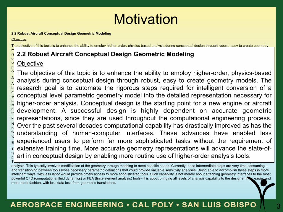
Motivation 2.2 Robust Aircraft Conceptual Design Geometric Modeling Objective
The objective of this topic is to enhance the ability to employ higher-order, physics-based analysis during conceptual design through robust, easy to create geometry models. The research goal is to automate the rigorous steps required for intelligent conversion of a conceptual level parametric geometry model into the detailed representation necessary for higher-order analysis. Conceptual design is the starting point for a new engine or aircraft development. A successful design is highly dependent on accurate geometric representations, since they are used throughout the computational engineering process. Over the past several decades computational capability has drastically improved as has the understanding of human-computer interfaces. These advances have enabled less experienced users to perform far more sophisticated tasks without the requirement of extensive training time. More accurate geometry representations will advance the state-of-art in conceptual design by enabling more routine use of higher-order analysis tools.
Approach
A key need of conceptual design is the ability to quickly articulate ideas and engineering concepts into a digital 3-D database. While this can be accomplished through building a CAD (computer aided design) model of the geometry, it would be valuable to have the ability to parameterize the geometry’s characteristics. Parametric overlays to CAD programs can be performed, but there can be negative implications to this approach. For instance, it requires users to obtain often expensive software, and there can be inherent limitations with a given CAD package. Therefore, a prerequisite of any valuable conceptual design geometry solution is that it be parametric-input based and use aircraft design terminology to communicate effectively with the user (e.g., span, aspect ratio, chord). Currently, there are no accepted standards for parametric-based geometry representations to facilitate sharing of geometry. There is a need to create a generalized standard for parametric geometry and an approach to transfer geometry models in that standard to CADbased models. These new approaches to streamline the conversion of conceptual geometry to the geometry representation needs of more detailed analysis, however, should not diminish the ability to rapidly explore the conceptual design space using a parametric geometry tool.
NASA has made prior investments in the development of a parametric geometry tool for conceptual design [i.e., Vehicle Sketch Pad (VSP)]. There is a need, however, to create better coupling between higher-order engineering analysis codes and geometry tools like VSP. The developed geometry methods should be flexible in nature and must be compatible with, and support, NASA’s existing ModelCenter-based systems analysis and conceptual design process. An overview of the tools used in a ModelCenter environment is available in the “Other Documents” section at: http://nspires.nasaprs.com/external/solicitations.
Expected Outcome
The new capability shall provide parametric-based geometry modeling and analysis methodologies that enable conceptual designers to accomplish analyses in a faster, easier manner. In addition, the geometric representation will enable transferring of key geometry for use with higher-order aerodynamics, structural, mass properties, propulsion, control, aeroelastic, aeroacoustic, and aeropropulsive tools. However, developing an export capability/linkage to another tool is not sufficient. The goal is to embed in the tools the rigorous steps required for intelligent conversion of the geometric database into the necessary information for the higher-order analysis. This typically involves modification of the geometry through meshing to meet specific needs. Currently these intermediate steps are very time consuming – and transitioning between tools loses necessary parametric definitions that could provide valuable sensitivity analyses. Being able to accomplish these steps in more intelligent ways, with less labor would provide timely access to more sophisticated tools. Such capability is not merely about attaching geometry interfaces to the most powerful CFD (computational fluid dynamics) or FEA (finite element analysis) tools– it is about bringing all levels of analysis capability to the designer in an easier and more rapid fashion, with less data loss from geometric translations.
2.2 Robust Aircraft Conceptual Design Geometric Modeling Objective The objective of this topic is to enhance the ability to employ higher-order, physics-based analysis during conceptual design through robust, easy to create geometry models. The research goal is to automate the rigorous steps required for intelligent conversion of a conceptual level parametric geometry model into the detailed representation necessary for higher-order analysis. Conceptual design is the starting point for a new engine or aircraft development. A successful design is highly dependent on accurate geometric representations, since they are used throughout the computational engineering process. Over the past several decades computational capability has drastically improved as has the understanding of human-computer interfaces. These advances have enabled less experienced users to perform far more sophisticated tasks without the requirement of extensive training time. More accurate geometry representations will advance the state-of-art in conceptual design by enabling more routine use of higher-order analysis tools.
4
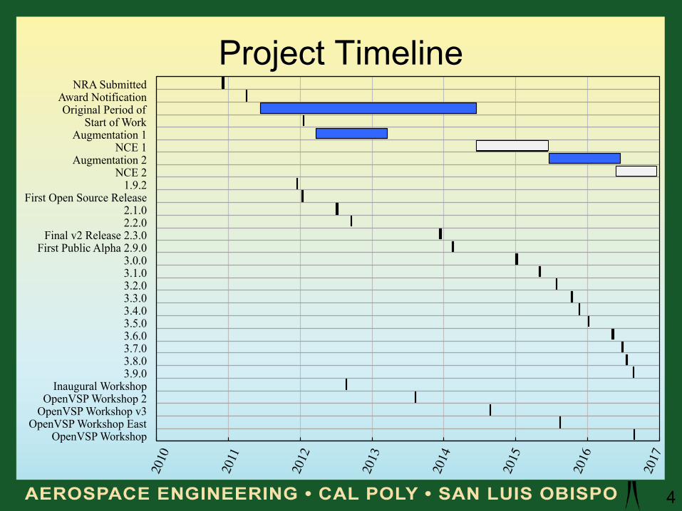
Project Timeline NRA Submitted
Award Notification Original Period of
Start of Work Augmentation 1
NCE 1 Augmentation 2
NCE 2 1.9.2
First Open Source Release 2.1.0 2.2.0
Final v2 Release 2.3.0 First Public Alpha 2.9.0
3.0.0 3.1.0 3.2.0 3.3.0 3.4.0 3.5.0 3.6.0 3.7.0 3.8.0 3.9.0
Inaugural Workshop OpenVSP Workshop 2
OpenVSP Workshop v3 OpenVSP Workshop East
OpenVSP Workshop
5
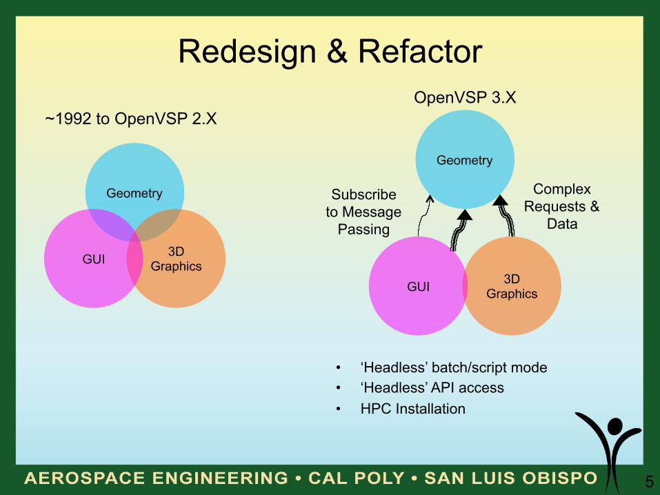
Redesign & Refactor
Geometry
3D Graphics GUI
~1992 to OpenVSP 2.X
Geometry
3D Graphics GUI
OpenVSP 3.X
Complex Requests &
Data
Subscribe to Message
Passing
• ‘Headless’ batch/script mode • ‘Headless’ API access • HPC Installation
6
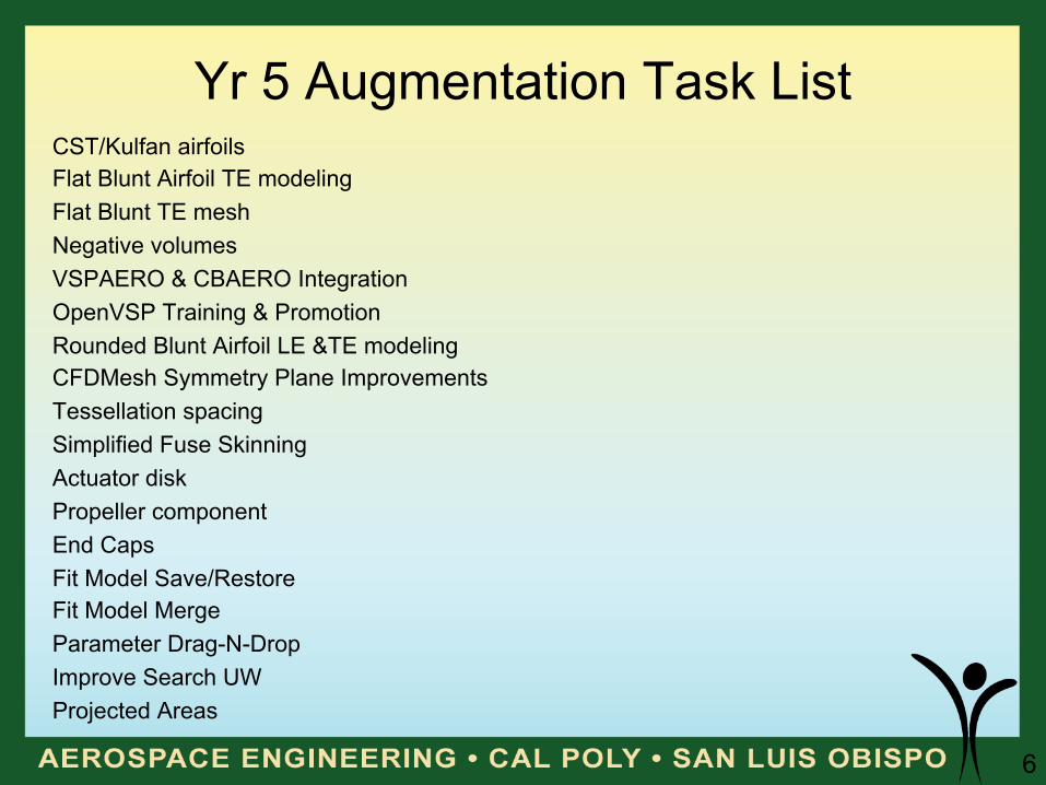
Yr 5 Augmentation Task List CST/Kulfan airfoils Flat Blunt Airfoil TE modeling Flat Blunt TE mesh Negative volumes VSPAERO & CBAERO Integration OpenVSP Training & Promotion Rounded Blunt Airfoil LE &TE modeling CFDMesh Symmetry Plane Improvements Tessellation spacing Simplified Fuse Skinning Actuator disk Propeller component End Caps Fit Model Save/Restore Fit Model Merge Parameter Drag-N-Drop Improve Search UW Projected Areas
7
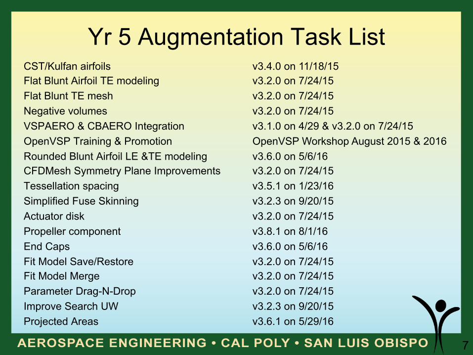
Yr 5 Augmentation Task List CST/Kulfan airfoils Flat Blunt Airfoil TE modeling Flat Blunt TE mesh Negative volumes VSPAERO & CBAERO Integration OpenVSP Training & Promotion Rounded Blunt Airfoil LE &TE modeling CFDMesh Symmetry Plane Improvements Tessellation spacing Simplified Fuse Skinning Actuator disk Propeller component End Caps Fit Model Save/Restore Fit Model Merge Parameter Drag-N-Drop Improve Search UW Projected Areas
v3.4.0 on 11/18/15 v3.2.0 on 7/24/15 v3.2.0 on 7/24/15 v3.2.0 on 7/24/15 v3.1.0 on 4/29 & v3.2.0 on 7/24/15 OpenVSP Workshop August 2015 & 2016 v3.6.0 on 5/6/16 v3.2.0 on 7/24/15 v3.5.1 on 1/23/16 v3.2.3 on 9/20/15 v3.2.0 on 7/24/15 v3.8.1 on 8/1/16 v3.6.0 on 5/6/16 v3.2.0 on 7/24/15 v3.2.0 on 7/24/15 v3.2.0 on 7/24/15 v3.2.3 on 9/20/15 v3.6.1 on 5/29/16
8
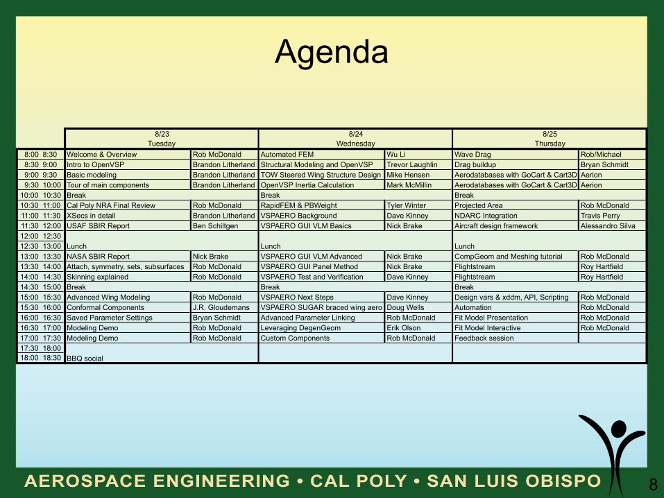
Agenda
8:00 8:30 Welcome & Overview Rob McDonald Automated FEM Wu Li Wave Drag Rob/Michael8:30 9:00 Intro to OpenVSP Brandon Litherland Structural Modeling and OpenVSP Trevor Laughlin Drag buildup Bryan Schmidt9:00 9:30 Basic modeling Brandon Litherland TOW Steered Wing Structure Design Mike Hensen Aerodatabases with GoCart & Cart3D Aerion9:30 10:00 Tour of main components Brandon Litherland OpenVSP Inertia Calculation Mark McMillin Aerodatabases with GoCart & Cart3D Aerion
10:00 10:3010:30 11:00 Cal Poly NRA Final Review Rob McDonald RapidFEM & PBWeight Tyler Winter Projected Area Rob McDonald11:00 11:30 XSecs in detail Brandon Litherland VSPAERO Background Dave Kinney NDARC Integration Travis Perry11:30 12:00 USAF SBIR Report Ben Schiltgen VSPAERO GUI VLM Basics Nick Brake Aircraft design framework Alessandro Silva12:00 12:3012:30 13:0013:00 13:30 NASA SBIR Report Nick Brake VSPAERO GUI VLM Advanced Nick Brake CompGeom and Meshing tutorial Rob McDonald13:30 14:00 Attach, symmetry, sets, subsurfaces Rob McDonald VSPAERO GUI Panel Method Nick Brake Flightstream Roy Hartfield14:00 14:30 Skinning explained Rob McDonald VSPAERO Test and Verification Dave Kinney Flightstream Roy Hartfield14:30 15:0015:00 15:30 Advanced Wing Modeling Rob McDonald VSPAERO Next Steps Dave Kinney Design vars & xddm, API, Scripting Rob McDonald15:30 16:00 Conformal Components J.R. Gloudemans VSPAERO SUGAR braced wing aero Doug Wells Automation Rob McDonald16:00 16:30 Saved Parameter Settings Bryan Schmidt Advanced Parameter Linking Rob McDonald Fit Model Presentation Rob McDonald16:30 17:00 Modeling Demo Rob McDonald Leveraging DegenGeom Erik Olson Fit Model Interactive Rob McDonald17:00 17:30 Modeling Demo Rob McDonald Custom Components Rob McDonald Feedback session17:30 18:0018:00 18:30 BBQ social
Break Break Break
Break Break Break
LunchLunchLunch
8/23 8/24 8/25Tuesday Wednesday Thursday
9
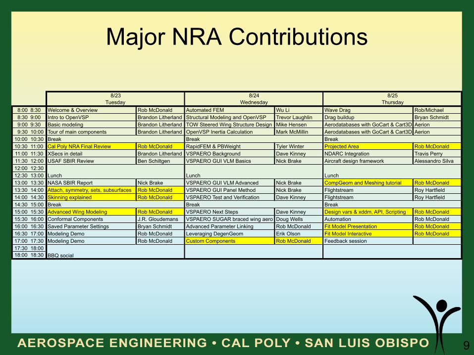
Major NRA Contributions
8:00 8:30 Welcome & Overview Rob McDonald Automated FEM Wu Li Wave Drag Rob/Michael8:30 9:00 Intro to OpenVSP Brandon Litherland Structural Modeling and OpenVSP Trevor Laughlin Drag buildup Bryan Schmidt9:00 9:30 Basic modeling Brandon Litherland TOW Steered Wing Structure Design Mike Hensen Aerodatabases with GoCart & Cart3D Aerion9:30 10:00 Tour of main components Brandon Litherland OpenVSP Inertia Calculation Mark McMillin Aerodatabases with GoCart & Cart3D Aerion
10:00 10:3010:30 11:00 Cal Poly NRA Final Review Rob McDonald RapidFEM & PBWeight Tyler Winter Projected Area Rob McDonald11:00 11:30 XSecs in detail Brandon Litherland VSPAERO Background Dave Kinney NDARC Integration Travis Perry11:30 12:00 USAF SBIR Review Ben Schiltgen VSPAERO GUI VLM Basics Nick Brake Aircraft design framework Alessandro Silva12:00 12:3012:30 13:0013:00 13:30 NASA SBIR Report Nick Brake VSPAERO GUI VLM Advanced Nick Brake CompGeom and Meshing tutorial Rob McDonald13:30 14:00 Attach, symmetry, sets, subsurfaces Rob McDonald VSPAERO GUI Panel Method Nick Brake Flightstream Roy Hartfield14:00 14:30 Skinning explained Rob McDonald VSPAERO Test and Verification Dave Kinney Flightstream Roy Hartfield14:30 15:0015:00 15:30 Advanced Wing Modeling Rob McDonald VSPAERO Next Steps Dave Kinney Design vars & xddm, API, Scripting Rob McDonald15:30 16:00 Conformal Components J.R. Gloudemans VSPAERO SUGAR braced wing aero Doug Wells Automation Rob McDonald16:00 16:30 Saved Parameter Settings Bryan Schmidt Advanced Parameter Linking Rob McDonald Fit Model Presentation Rob McDonald16:30 17:00 Modeling Demo Rob McDonald Leveraging DegenGeom Erik Olson Fit Model Interactive Rob McDonald17:00 17:30 Modeling Demo Rob McDonald Custom Components Rob McDonald Feedback session17:30 18:0018:00 18:30 BBQ social
Lunch Lunch Lunch
Break Break Break
Tuesday Wednesday Thursday
Break Break Break
8/23 8/24 8/25
10
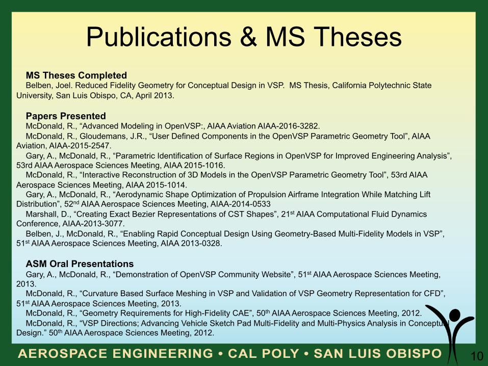
Publications & MS Theses MS Theses Completed Belben, Joel. Reduced Fidelity Geometry for Conceptual Design in VSP. MS Thesis, California Polytechnic State
University, San Luis Obispo, CA, April 2013. Papers Presented McDonald, R., “Advanced Modeling in OpenVSP:, AIAA Aviation AIAA-2016-3282. McDonald, R., Gloudemans, J.R., “User Defined Components in the OpenVSP Parametric Geometry Tool”, AIAA
Aviation, AIAA-2015-2547. Gary, A., McDonald, R., “Parametric Identification of Surface Regions in OpenVSP for Improved Engineering Analysis”,
53rd AIAA Aerospace Sciences Meeting, AIAA 2015-1016. McDonald, R., “Interactive Reconstruction of 3D Models in the OpenVSP Parametric Geometry Tool”, 53rd AIAA
Aerospace Sciences Meeting, AIAA 2015-1014. Gary, A., McDonald, R., “Aerodynamic Shape Optimization of Propulsion Airframe Integration While Matching Lift
Distribution”, 52nd AIAA Aerospace Sciences Meeting, AIAA-2014-0533 Marshall, D., “Creating Exact Bezier Representations of CST Shapes”, 21st AIAA Computational Fluid Dynamics
Conference, AIAA-2013-3077. Belben, J., McDonald, R., “Enabling Rapid Conceptual Design Using Geometry-Based Multi-Fidelity Models in VSP”,
51st AIAA Aerospace Sciences Meeting, AIAA 2013-0328. ASM Oral Presentations Gary, A., McDonald, R., “Demonstration of OpenVSP Community Website”, 51st AIAA Aerospace Sciences Meeting,
2013. McDonald, R., “Curvature Based Surface Meshing in VSP and Validation of VSP Geometry Representation for CFD”,
51st AIAA Aerospace Sciences Meeting, 2013. McDonald, R., “Geometry Requirements for High-Fidelity CAE”, 50th AIAA Aerospace Sciences Meeting, 2012. McDonald, R., “VSP Directions; Advancing Vehicle Sketch Pad Multi-Fidelity and Multi-Physics Analysis in Conceptual
Design.” 50th AIAA Aerospace Sciences Meeting, 2012.
11
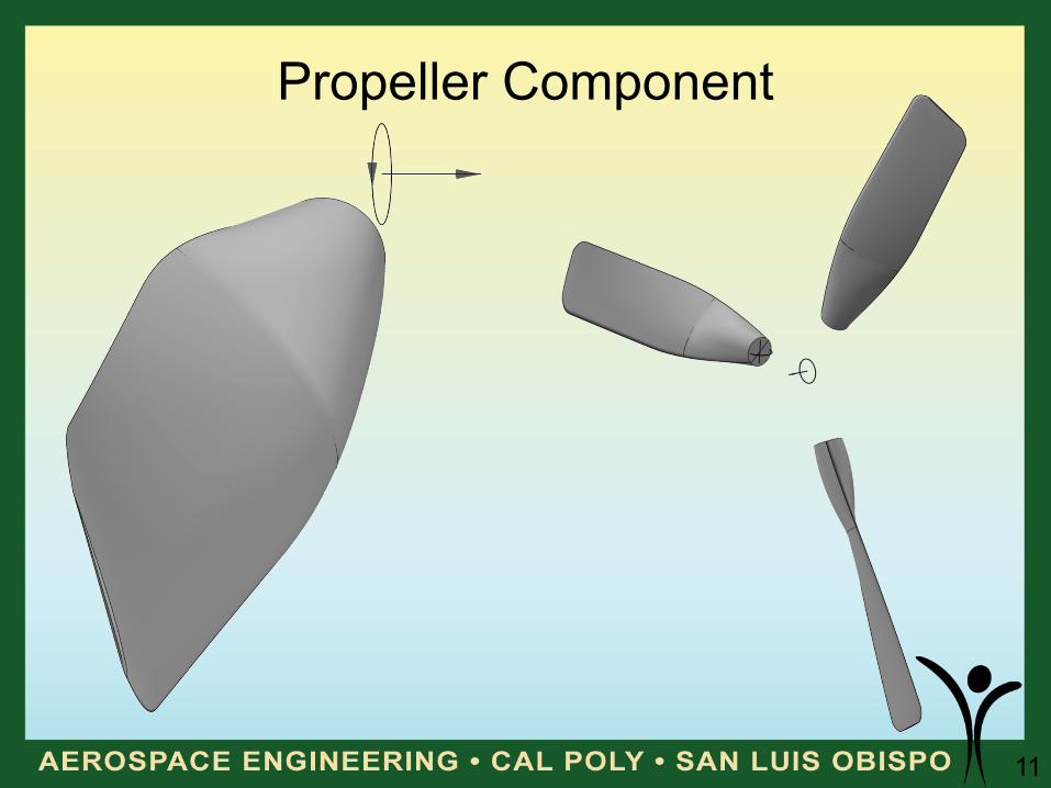
Propeller Component
12
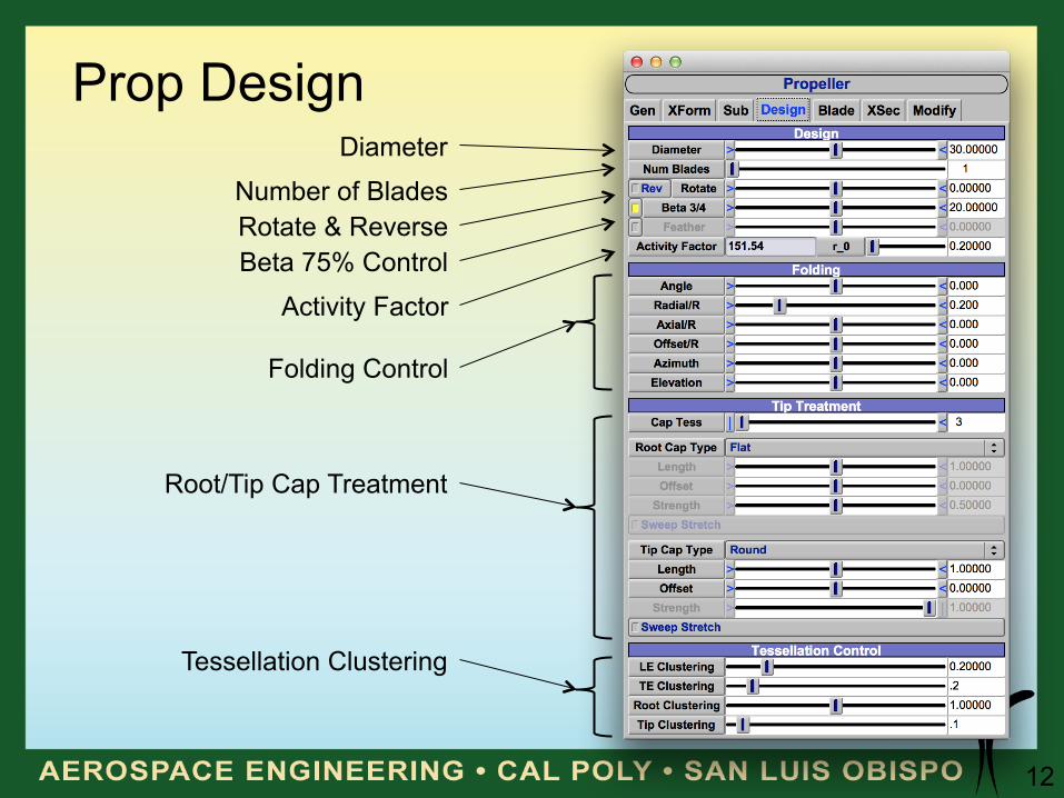
Prop Design
Activity Factor
Folding Control
Root/Tip Cap Treatment
Tessellation Clustering
Beta 75% Control Rotate & Reverse
Diameter
Number of Blades
13
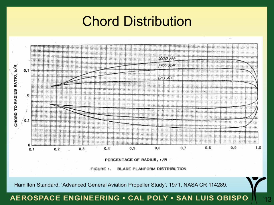
Chord Distribution
Hamilton Standard, ‘Advanced General Aviation Propeller Study’, 1971, NASA CR 114289.
14
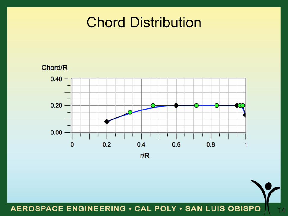
Chord Distribution
15
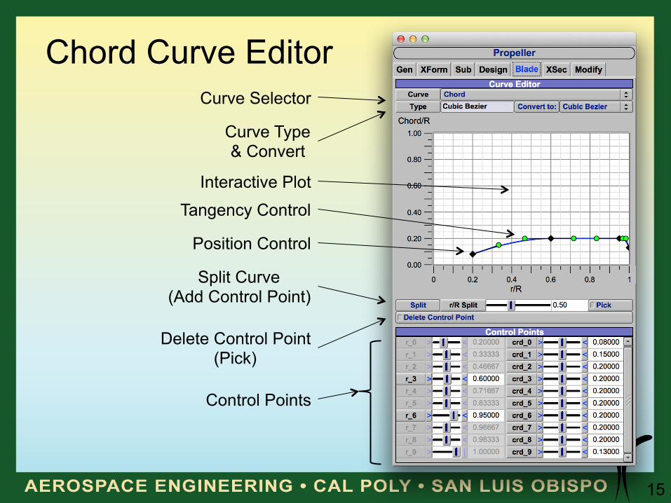
Chord Curve Editor
Control Points
Tangency Control
Position Control
Interactive Plot
Split Curve (Add Control Point)
Delete Control Point (Pick)
Curve Selector
Curve Type & Convert
16
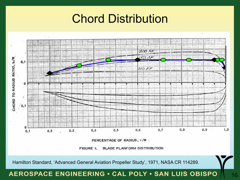
Chord Distribution
Hamilton Standard, ‘Advanced General Aviation Propeller Study’, 1971, NASA CR 114289.
17
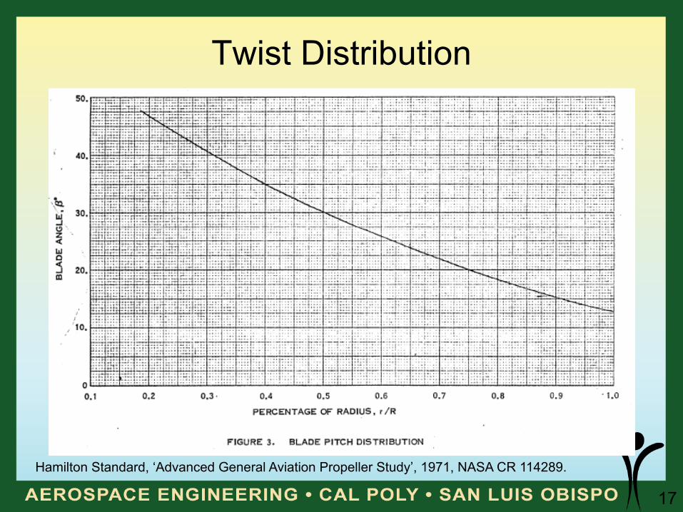
Twist Distribution
Hamilton Standard, ‘Advanced General Aviation Propeller Study’, 1971, NASA CR 114289.
18
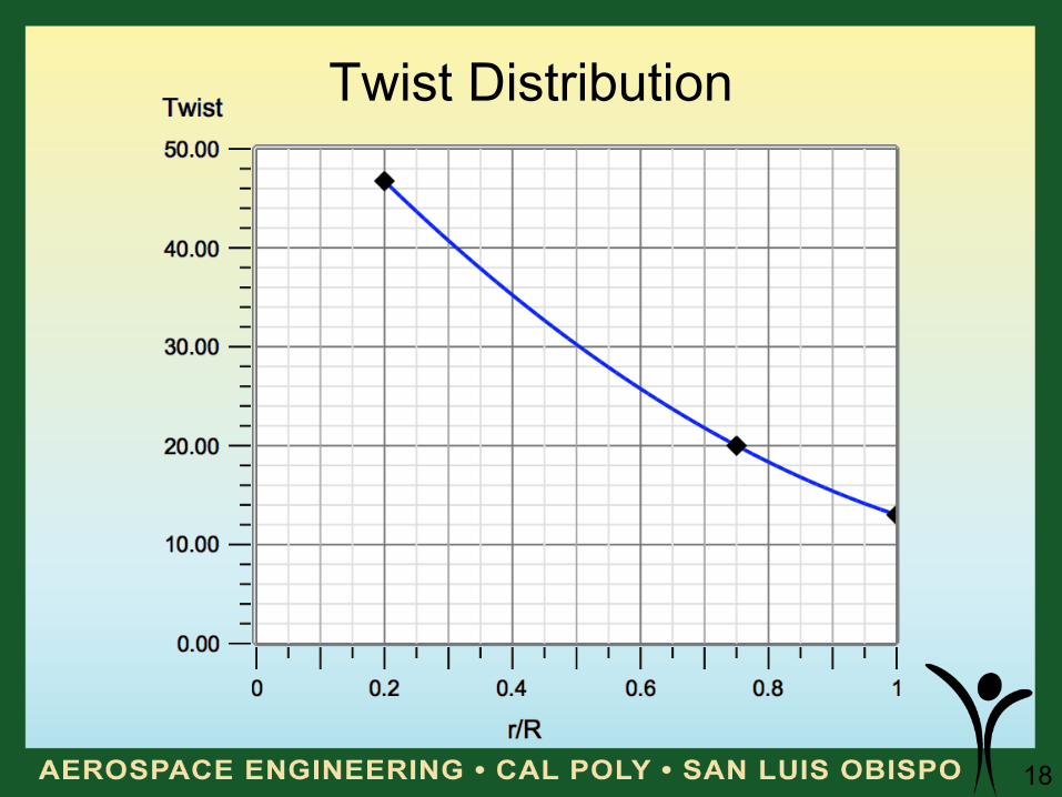
Twist Distribution
19
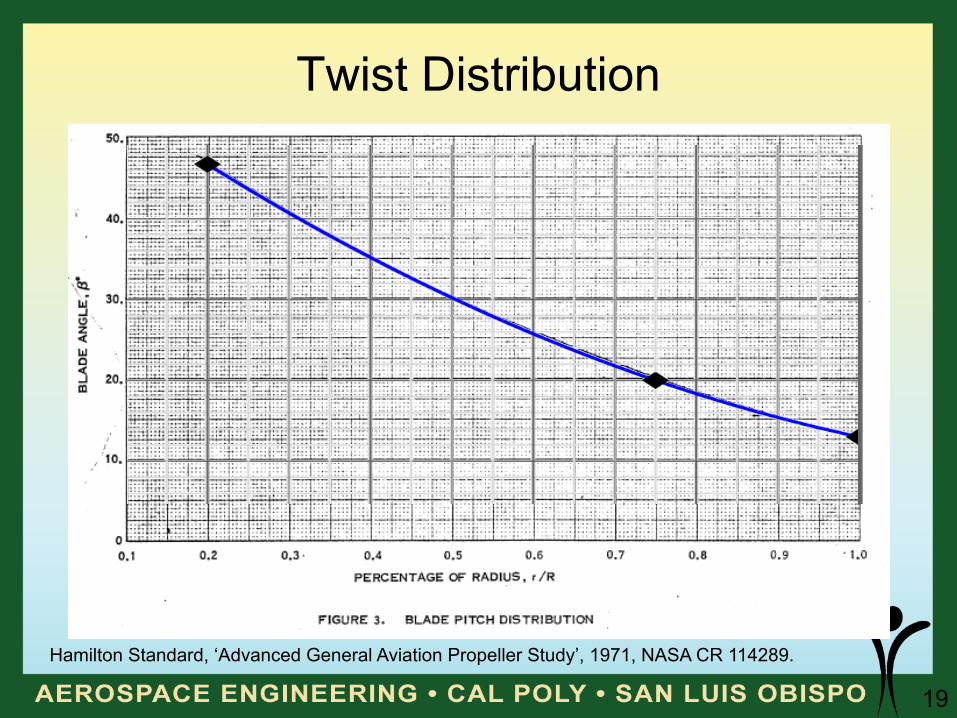
Twist Distribution
Hamilton Standard, ‘Advanced General Aviation Propeller Study’, 1971, NASA CR 114289.
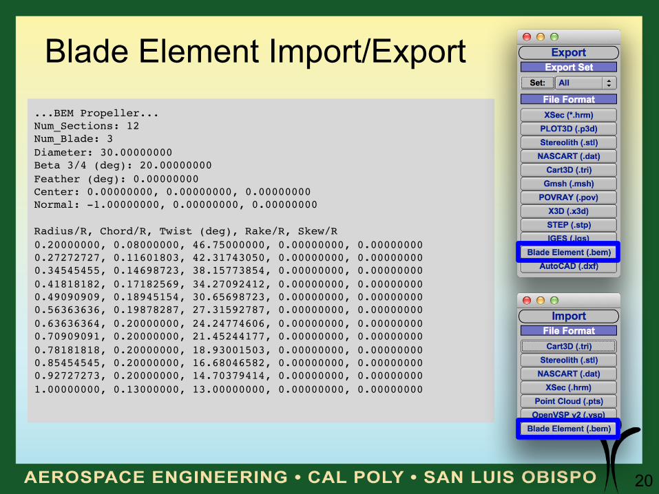
20
Blade Element Import/Export ...BEM Propeller...!Num_Sections: 12!Num_Blade: 3!Diameter: 30.00000000!Beta 3/4 (deg): 20.00000000!Feather (deg): 0.00000000!Center: 0.00000000, 0.00000000, 0.00000000!Normal: -1.00000000, 0.00000000, 0.00000000!!Radius/R, Chord/R, Twist (deg), Rake/R, Skew/R!0.20000000, 0.08000000, 46.75000000, 0.00000000, 0.00000000!0.27272727, 0.11601803, 42.31743050, 0.00000000, 0.00000000!0.34545455, 0.14698723, 38.15773854, 0.00000000, 0.00000000!0.41818182, 0.17182569, 34.27092412, 0.00000000, 0.00000000!0.49090909, 0.18945154, 30.65698723, 0.00000000, 0.00000000!0.56363636, 0.19878287, 27.31592787, 0.00000000, 0.00000000!0.63636364, 0.20000000, 24.24774606, 0.00000000, 0.00000000!0.70909091, 0.20000000, 21.45244177, 0.00000000, 0.00000000!0.78181818, 0.20000000, 18.93001503, 0.00000000, 0.00000000!0.85454545, 0.20000000, 16.68046582, 0.00000000, 0.00000000!0.92727273, 0.20000000, 14.70379414, 0.00000000, 0.00000000!1.00000000, 0.13000000, 13.00000000, 0.00000000, 0.00000000!
21
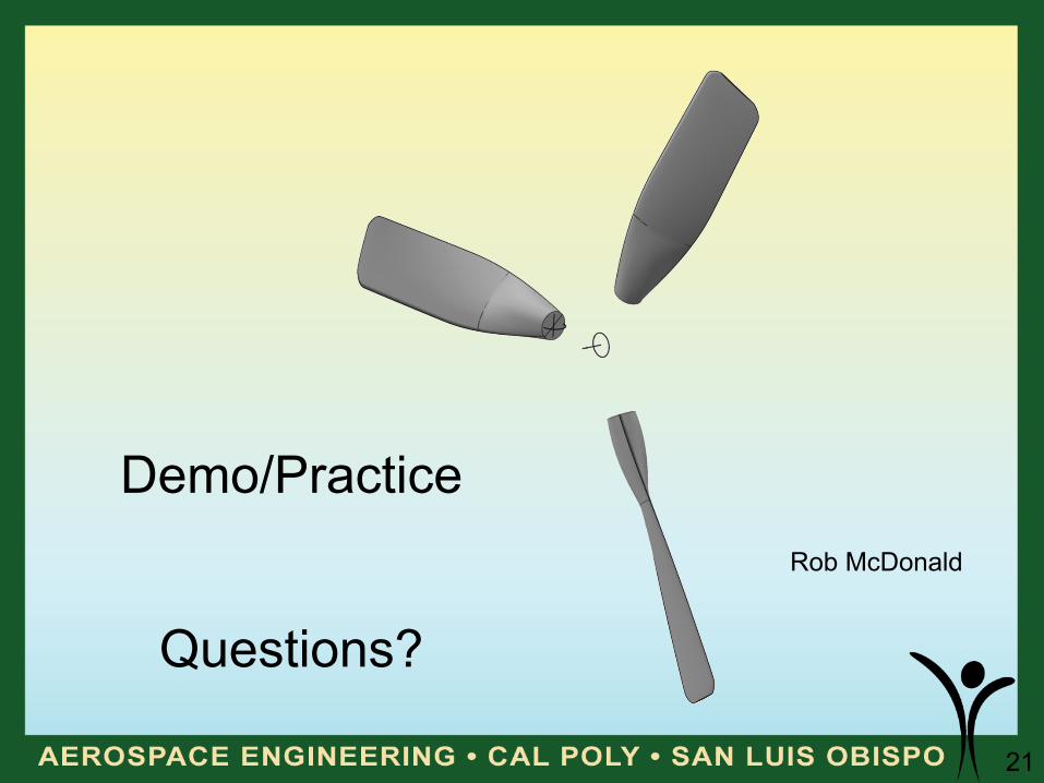
Demo/Practice
Questions?
Rob McDonald