Embed Size (px)
Citation preview
An Active Wideband Reference Target for the
Calibration of Ground to Air Radar Systems
Monique Pienaar1, Johann W. Odendaal
1, Jacques E. Cilliers
2, Kevin H. Kloke
2 and Johan Joubert
1
1 Centre for Electromagnetism, Department of EEC Engineering, University of Pretoria, South Africa;
Corresponding author: [email protected]
2 Radar and Electronic Warfare Systems, Defence Peace Safety and Security, Council for Scientific
and Industrial Research (CSIR), South Africa
ABSTRACT— The radar cross section (RCS) of passive calibration targets is relatively low, which
leads to a commensurate increase in the uncertainty of the radar’s calibration. To address this
deficiency, an active radar calibration (ARC) target was developed, which was mounted on a small
remote controlled tri-copter and used for radar calibration. Results are presented for this relatively
small, light weight and cost effective airborne ARC, which is suitable for the calibration of a ground
to air RCS measurement system. The static RCS characteristics of the airborne ARC target were
measured in a compact range and compared to outdoor measurements with the ARC target mounted
on the tri-copter. The airborne capability of the calibration target was used to reduce the effects of
multi-path and clutter.
Key words: active calibration target; airborne calibration target; wideband calibration target; radar
cross section
1. INTRODUCTION
Modern radar systems are becoming increasingly capable of measuring the scattering signatures
(possibly fully polarimetric) of targets (airborne, land, sea, space and even underground) to enable
better discrimination of targets from clutter as well as target recognition functionality. Accurate
calibration of radar systems is thus required to increase measurement accuracy of the absolute Radar
Cross Section (RCS). Calibration of radar systems is usually performed by measuring the backscatter
of a calibration target with a known RCS value [1].
Radar systems are usually calibrated with passive calibration targets, mostly spheres, dihedral- and
trihedral-corner reflectors or Luneburg Lenses [2]. The RCS of passive calibration targets is directly
proportional to their electrical aperture, therefore large passive calibration targets are required to
achieve accurate calibration. In order to achieve a backscatter signal which is significantly larger than
the radar system’s noise floor requires a physically large passive calibration target, which increases
the complexity of manufacturing, transportation and deployment. Increasing the electrical aperture,
therefore the physical size, of the passive calibration target to increase the RCS, also results in a
decrease in scattering beamwidth in some cases, which leads to increased sensitivity to target
alignment. The relatively low RCS values or narrow elevation or azimuth beamwidths of passive
calibration targets and the resulting increase in the uncertainty of measurements are the main
disadvantages of passive calibration targets. The use of ground based active radar calibration (ARC)
targets for the calibration of airborne Synthetic Aperture Radar (SAR) systems was proposed in the
1980s [3] and was recently demonstrated for fully polarimetric SAR systems [4].
The limitations of passive calibration targets can be alleviated by using an airborne active calibration
target, suitable for the calibration of a ground to air radar system. In this paper results are presented
for a relatively small (33x18x11 cm) and light weight (500 g) airborne active calibration target. The
target has wide bandwidth (3 GHz to 6 GHz) and wide beamwidth (approximately 20 degrees)
properties. The target can easily be configured for the calibration of VV-, VH-, HV- and HH-
polarized ground to air radar systems. The static RCS characteristics of the airborne active calibration
target were measured in the compact range of the University of Pretoria (South Africa). Outdoor
measurements of the active calibration target, with the target mounted on a small remote controlled
tri-copter, were conducted at the Defence Peace Safety and Security (DPSS) unit of the Council for
Scientific and Industrial Research (CSIR).
2. WIDE BAND ACTIVE CALIBRATION TARGET
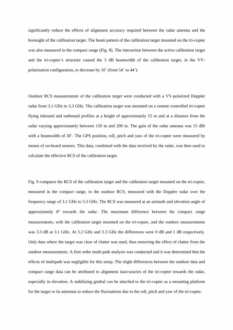
This low cost, airborne active calibration target consists of two antennas (one for receive and one for
transmit), an amplifier to increase the effective RCS values of the calibration target and an optional
attenuator. A schematic diagram the active calibration target is shown in Fig. 1. The attenuator allows
the RCS of the calibration target to be varied over a large dynamic range. Two light weight printed
Vivaldi antennas were implemented which have wide bandwidth characteristics and low cross-
polarization levels with relatively high gain. Their reasonably broad radiation patterns make it easier
to align the calibration target and the radar [5]. The Vivaldi antennas were designed using Antenna
Magus [6] and simulated in FEKO [7]. The isolator protects the amplifier from any potential feedback
between the transmit and receive antennas.
The theoretical RCS of an active calibration target is given by [8]:
𝜎𝑒𝑓𝑓 = 𝐺𝑙𝑜𝑜𝑝𝐺𝑟𝐺𝑡𝜆2
4𝜋 (1)
with 𝐺𝑟 the gain of the receive antenna, 𝐺𝑡 the gain of the transmit antenna, 𝜆 the radar wavelength
and
𝐺𝑙𝑜𝑜𝑝 = 𝐺𝑎 − 𝐺𝑎𝑡𝑡 − 𝐺𝑖𝑠𝑜𝑙𝑎𝑡𝑜𝑟 (2)
where 𝐺𝑎 is the amplifier gain, 𝐺𝑎𝑡𝑡 is the attenuation of the attenuator and 𝐺𝑖𝑠𝑜𝑙𝑎𝑡𝑜𝑟 is the loss of the
isolator in dB. The RCS values of the calibration target can be estimated from the measured values of
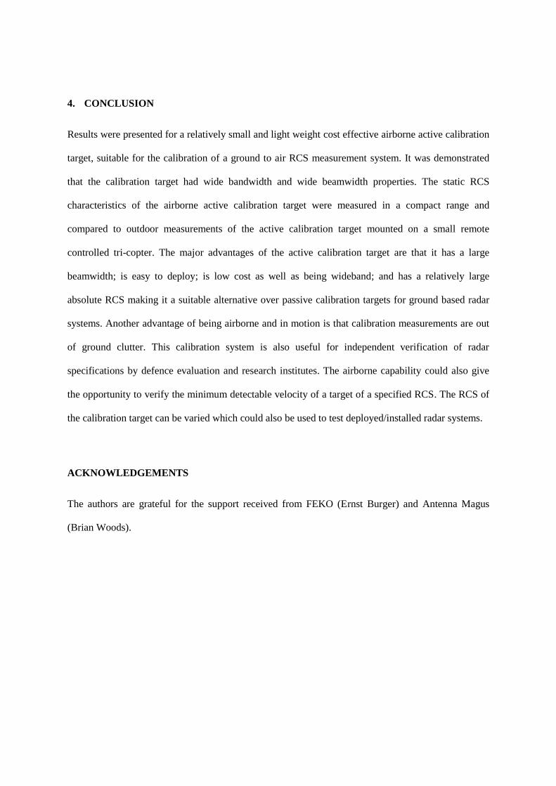
the individual components in Fig. 1. The antenna gains of the two Vivaldi antennas were measured in
the compact range and are shown in Fig. 2. The antenna gain increases form 8.7 dBi at 3 GHz to 12.6
dBi at 6 GHz. The mutual coupling between the two antennas was measured in the compact range for
a VV-polarized configured calibration target and was below -20 dB as shown in Fig. 3.
The gain of the components and cables comprising 𝐺𝑙𝑜𝑜𝑝 was measured on a vector network analyser
and is shown in Fig. 4. The measured gain of the loop varied from 3.9 dB to 5.7 dB and from (1), the
theoretical RCS of the active target varied from 8.6 dBsm to 13.4 dBsm over the frequency band of
operation.
3. MEASURED RCS RESULTS OF THE ACTIVE CALIBRATION TARGET
The RCS characteristics of the active calibration target were measured in the compact range, a
photograph of the measurement setup is shown in Fig. 5. The target was measured for different
polarization configurations, viz. VV-, HH- and VH-polarization allowing the calibration target to be
used for the calibration of ground to air radar systems with different polarizations. The frequency
response for the different configurations on boresight are presented in Fig. 6, and compared to the
theoretical RCS of the target obtained from the gain and S-parameter measurements of the individual
components in Section 2. The maximum variation in the VV-polarization configuration was 2.5 dB.
The structural RCS of the calibration target (with the amplifier switched off) is also shown and is
below -7.8 dBsm over the frequency range which is significantly lower than the RCS of the active
target.
Fig. 7 shows the calibration target mounted on the tri-copter for deployment during the outdoor
measurements of the calibration target using an S-band ground based Doppler radar. The normalized
beam pattern of the active calibration target measured in the compact range for all the polarization
configurations are shown in Fig. 8. The 3 dB beamwidth of the calibration target is larger than 43˚ for
all the polarization configurations. This relatively broad beamwidth of the calibration target will
significantly reduce the effects of alignment accuracy required between the radar antenna and the
boresight of the calibration target. The beam pattern of the calibration target mounted on the tri-copter
was also measured in the compact range (Fig. 8). The interaction between the active calibration target
and the tri-copter’s structure caused the 3 dB beamwidth of the calibration target, in the VV-
polarization configuration, to decrease by 10˚ (from 54˚ to 44˚).
Outdoor RCS measurements of the calibration target were conducted with a VV-polarized Doppler
radar from 3.1 GHz to 3.3 GHz. The calibration target was mounted on a remote controlled tri-copter
flying inbound and outbound profiles at a height of approximately 15 m and at a distance from the
radar varying approximately between 150 m and 200 m. The gain of the radar antenna was 15 dBi
with a beamwidth of 30˚. The GPS position, roll, pitch and yaw of the tri-copter were measured by
means of on-board sensors. This data, combined with the data received by the radar, was then used to
calculate the effective RCS of the calibration target.
Fig. 9 compares the RCS of the calibration target and the calibration target mounted on the tri-copter,
measured in the compact range, to the outdoor RCS, measured with the Doppler radar over the
frequency range of 3.1 GHz to 3.3 GHz. The RCS was measured at an azimuth and elevation angle of
approximately 0° towards the radar. The maximum difference between the compact range
measurements, with the calibration target mounted on the tri-copter, and the outdoor measurements
was 3.3 dB at 3.1 GHz. At 3.2 GHz and 3.3 GHz the differences were 0 dB and 1 dB respectively.
Only data where the target was clear of clutter was used, thus removing the effect of clutter from the
outdoor measurements. A first order multi-path analysis was conducted and it was determined that the
effects of multipath was negligible for this setup. The slight differences between the outdoor data and
compact range data can be attributed to alignment inaccuracies of the tri-copter towards the radar,
especially in elevation. A stabilizing gimbal can be attached to the tri-copter as a mounting platform
for the target or its antennas to reduce the fluctuations due to the roll, pitch and yaw of the tri-copter.
4. CONCLUSION
Results were presented for a relatively small and light weight cost effective airborne active calibration
target, suitable for the calibration of a ground to air RCS measurement system. It was demonstrated
that the calibration target had wide bandwidth and wide beamwidth properties. The static RCS
characteristics of the airborne active calibration target were measured in a compact range and
compared to outdoor measurements of the active calibration target mounted on a small remote
controlled tri-copter. The major advantages of the active calibration target are that it has a large
beamwidth; is easy to deploy; is low cost as well as being wideband; and has a relatively large
absolute RCS making it a suitable alternative over passive calibration targets for ground based radar
systems. Another advantage of being airborne and in motion is that calibration measurements are out
of ground clutter. This calibration system is also useful for independent verification of radar
specifications by defence evaluation and research institutes. The airborne capability could also give
the opportunity to verify the minimum detectable velocity of a target of a specified RCS. The RCS of
the calibration target can be varied which could also be used to test deployed/installed radar systems.
ACKNOWLEDGEMENTS
The authors are grateful for the support received from FEKO (Ernst Burger) and Antenna Magus
(Brian Woods).
REFERENCES
1. E. F. Knott, J. Shaeffer and M. Tuley, Radar Cross Section (RCS), USA: Scitech, 2004.
2. J. E. Heine, J. N. Devlin and D. L. Van Dyke, A unique radar calibration target, IEEE
Aerospace and Electronic Systems Magazine, 27 (2012), 8-15.
3. D. R. Burnfeldt and F. T. Ulaby, Active Reflector for Radar Calibration, IEEE Trans.
Geoscience and Remote Sencing 22 (1984), 165-169.
4. Y. Z. Li, Y. J. Luo and M. He, Dynamic polarimetric calibration using a single dual-polarized
antenna polarimetric active radar calibrator, In: IET International Radar Conf., Beijing,
China, 2013.
5. T. A. Vu, M. Z. Dooghabadi, S. Sudalaiyandi, H. A. Hjortland, O. Naess, T. S. Lande and S.
E. Hamran, UWB Vivaldi Antenna for Impulse Radio Beamforming, In: NORCHIP,
Trondheim, 2009.
6. Magus (Pty) Ltd, Antenna Magus, ver. 5.3.0, www.antennamagus.com.
7. FEKO Suite, ver. 7.0.2, Altair Development S.A., Stellenbosch, South Africa, 2015.
8. J. J. Ahne, K. Sarabandi and F. T. Ulaby, Design and implementation of single antenna
polarimetric active radar calibrators, In: International Symp. on Antennas and Propagation
Society, USA, 1993.
Figure 1. Active calibration target schematic.
Figure 2. Measured and simulated gain of the two Vivaldi antennas.
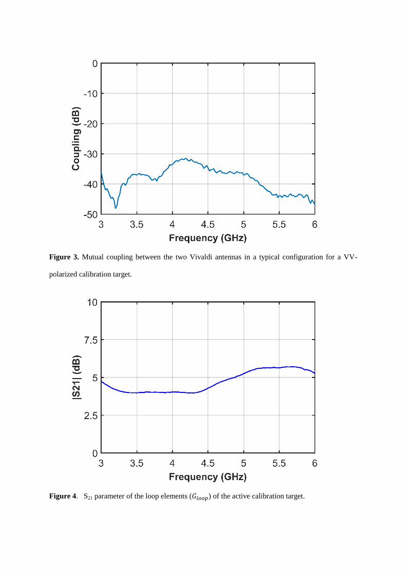
Figure 3. Mutual coupling between the two Vivaldi antennas in a typical configuration for a VV-
polarized calibration target.
Figure 4. S21 parameter of the loop elements (𝐺𝑙𝑜𝑜𝑝) of the active calibration target.
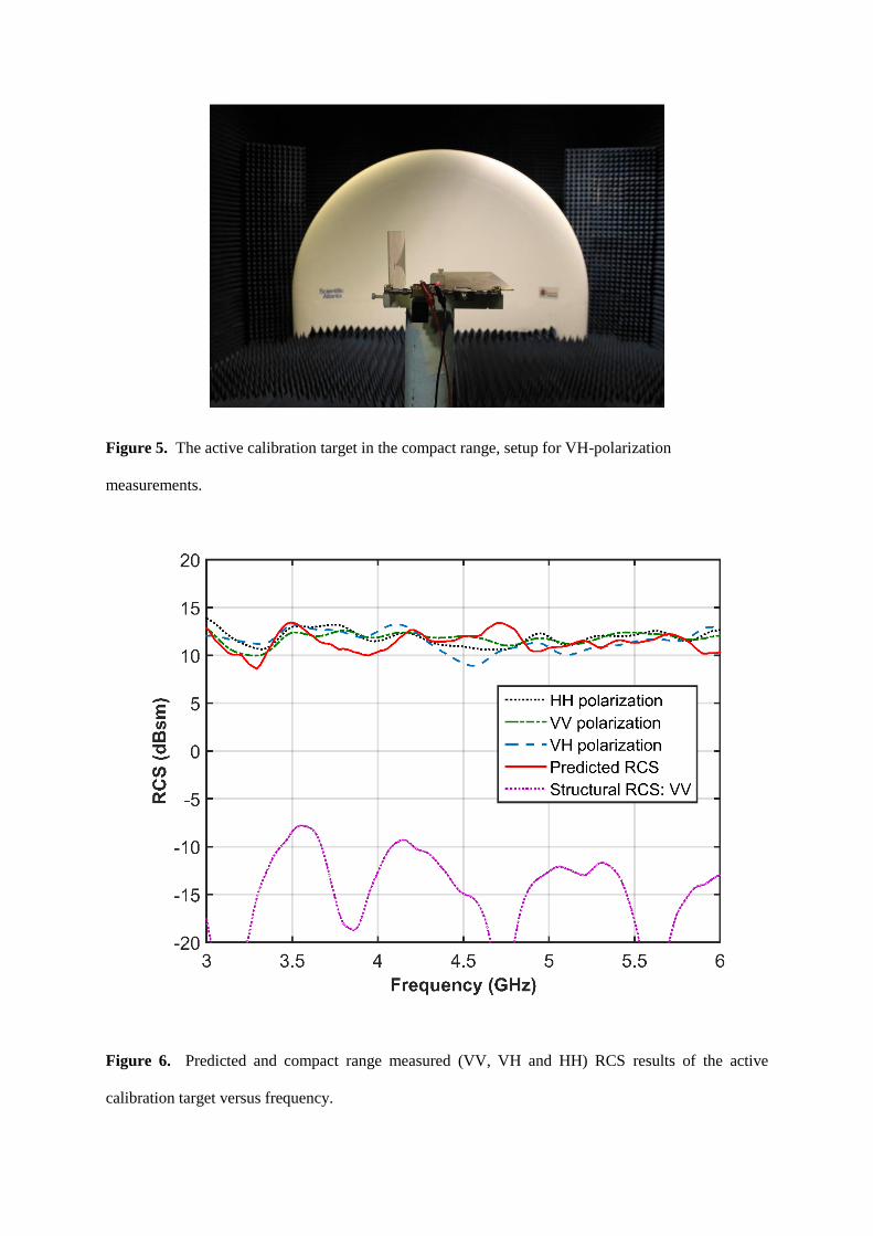
Figure 5. The active calibration target in the compact range, setup for VH-polarization
measurements.
Figure 6. Predicted and compact range measured (VV, VH and HH) RCS results of the active
calibration target versus frequency.
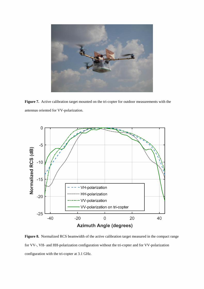
Figure 7. Active calibration target mounted on the tri-copter for outdoor measurements with the
antennas oriented for VV-polarization.
Figure 8. Normalized RCS beamwidth of the active calibration target measured in the compact range
for VV-, VH- and HH-polarization configuration without the tri-copter and for VV-polarization
configuration with the tri-copter at 3.1 GHz.
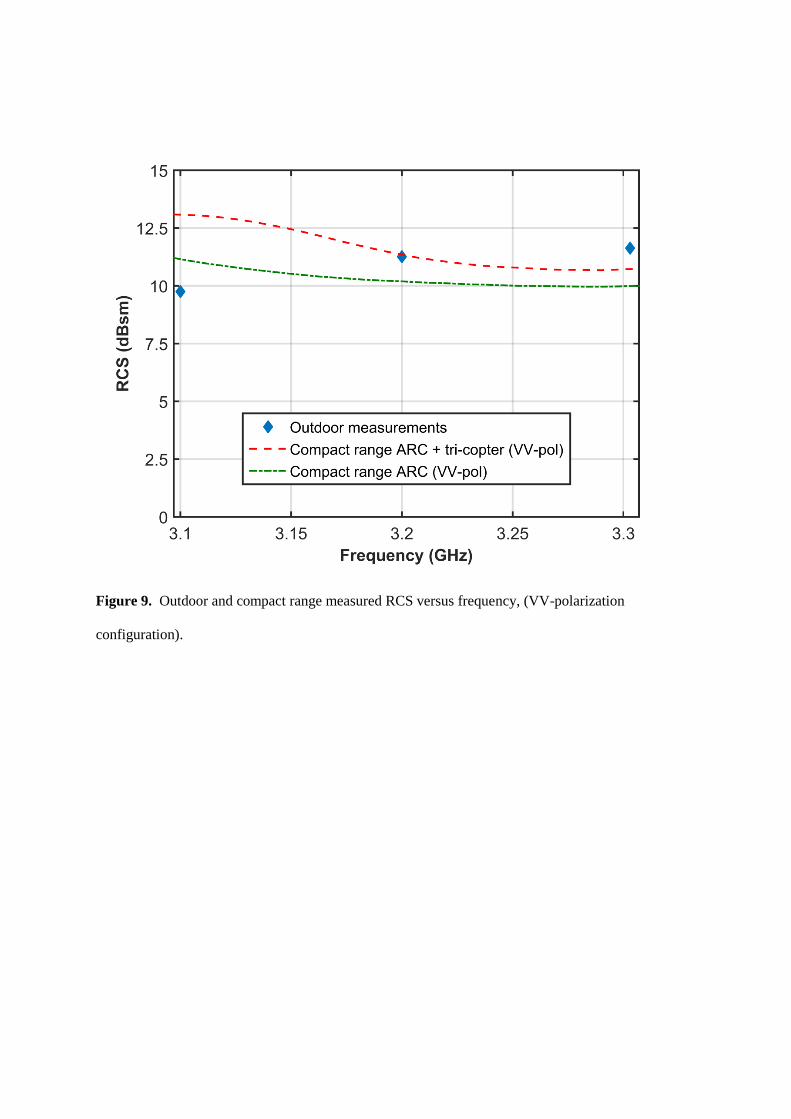
Figure 9. Outdoor and compact range measured RCS versus frequency, (VV-polarization
configuration).