Embed Size (px)
Citation preview
J. Vis. Commun. Image R. 14 (2003) 321–339
www.elsevier.com/locate/yjvci
An accurate bit-rate control algorithmfor video transcoding
Zhijun Lei* and Nicolas D. Georganas
Distributed and Collaborative Virtual Environment Research Laboratory, School of Information Technology
and Engineering, University of Ottawa, 800 King Edward Avenue, Ottawa, Canada K1N 6N5
Received 19 November 2001; accepted 21 February 2003
Abstract
In many video based applications, it is essential to precisely control the bit rate of video
streams for transmission over different networks and channel bandwidth. One critical element
in a bit rate control algorithm is the bit production model that predicts the number of pro-
duced bits when a certain quantization parameter is used. In this paper, we present a novel
bit allocation and rate control algorithm for compressed domain video transcoding. The spe-
cific transcoding issue mentioned is referred to as bit rate adaptation or rate shaping. We first
review the architectures of different bit rate adaptation transcoders and the generic rate con-
trol problem. Then, we propose and formulate an approximate linear bit allocation model,
which is based on experimental results. Based on this model, we propose an adaptive bit esti-
mation and allocation scheme for video transcoding. Implementation results show that the
proposed algorithm can provide accurate bit allocation, stable buffer occupancy and improved
video quality as compared to existing approaches. This rate control scheme can be used to pro-
vide flexible video bit rate adaptation and stable transmission of video streams over heteroge-
neous networks.
� 2003 Elsevier Science (USA). All rights reserved.
Keywords: Video transcoding; Bit rate control; H.263+; TMN-8; Bit production model; Rate distortion
theory
* Corresponding author.
E-mail addresses: [email protected] (Z. Lei), [email protected] (N.D. Georg-
anas).
1047-3203/$ - see front matter � 2003 Elsevier Science (USA). All rights reserved.
doi:10.1016/S1047-3203(03)00018-X
322 Z. Lei, N.D. Georganas / J. Vis. Commun. Image R. 14 (2003) 321–339
1. Introduction
With the explosive growth of the Internet and dramatic increase in wireless access,
there is a big demand for multimedia services over the wireless Internet. The third
generation (3G) wireless networks, anticipated to be the enabling technology forwireless multimedia services, are required to provide high bit rate data services of
144 kbps to 2 Mbps, which make feasible the providing of integrated services of data,
voice, audio and video across the wireless link. At the same time, the introduction of
new pervasive computing devices, such as PDAs, handheld computers, and smart
phones, allows users more ubiquitous access to multimedia services. However, in
some applications, such as Video on Demand, original video files are encoded at high
quality and high bit-rate. Real time downloading and playing those videos requires
several megabits per second bandwidth and is not suitable for handheld devices withlow bandwidth wireless connections. Therefore, the compressed video stream has to
be converted into a lower transmission bit rate. The operation of converting a video
in compressed format into another video also in compressed format is called Video
Transcoding, which is an essential technique for video communications over hetero-
geneous networks. The device that performs such an operation is called Video Trans-
coder. One of the most important functions of transcoders is bit rate conversion,
which accepts a precoded video stream as the input and produces another stream
with different bit rate to meet new constraints that are not known during the creationof the original precoded video. Irrespective of Constant Bit Rate (CBR), Variable Bit
Rate (VBR) channels, or best-effort connections, such as the Internet, a bit allocation
and rate control scheme must be used to make the transcoded stream meet the
channel bandwidth or packet size constraints.
1.1. Transcoder architectures
A video transcoder deals with converting a previously compressed video signalinto another compressed signal with a different format or bit rate. By video transcod-
ing, the precoded video file or real time captured video stream can be converted on
the fly according to the channel bandwidth and device requirements. There are three
major categories introduced in the literature for implementing video transcoders for
bit-rate adaptation. In the most straightforward method, a standard decoder and
a standard encoder are cascaded together. This close-loop transcoder is called
Cascaded Pixel Domain Transcoder (CPDT) (Youn and Sun, 2000). In the CPDT,
the decoder decompresses the incoming video stream, and then the encoder encodesthis reconstructed video into a different format or bit rate. Since the incoming video
stream is decompressed into raw pixels, which will be encoded again, CPDT involves
high processing complexity, memory and delay, thus is relatively inefficient for real
time applications. By reusing motion vectors and coding decision modes extracted
from the incoming video stream, Motion Estimation (ME) can be removed from
the transcoder, which reduces the most significant part of the computation cost.
The advantage of this architecture is its flexibility. Since transcoding is carried out
in the pixel domain, decoded video characteristics, such as spatial size or color,
Z. Lei, N.D. Georganas / J. Vis. Commun. Image R. 14 (2003) 321–339 323
can be modified and extra information, such as a logo or a digital watermark, can be
inserted into the video stream. As far as video quality is concerned, the CPDT can
get the best transcoding quality among all the transcoder architectures. On the other
extreme, the input video bitstream is first partially decoded to the DCT coefficient
level. Then, the bit rate can be easily scaled down by cutting higher frequency coef-ficients or by requantizing all coefficients with a larger quantization step size (Sun
et al., 1996). This kind of transcoders is also referred to as the Open-Loop Transcoder
(OLT). The OLT does not require entire decoding and encoding loops nor frame
store memory for reconstructed pictures, therefore saving significant complexity.
However, video quality of the OLT tends to degrade. Cutting higher frequency co-
efficients introduces blocky effect to video frames. Requantization error and loss of
higher frequency information also causes the video subject to drift.
In between the extremes of the above two methods is a third method, whichalso uses requantization of the DCT coefficients, but the requantization error is
stored in a frame buffer and is fed back to the requantizer to correct the requan-
tization error introduced in the previous frames (Zhu et al., 1999). This kind of
transcoder simplifies the architecture of the first category by merging two motion
compensation loops in the CPDT into one (Assunc�~aao and Ghanbri, 1996). If
motion compensation is carried out in the DCT domain (Chang and Mess-
erschimtt, 1993), the simplified transcoding can be performed totally in the
DCT domain, which results in a DCT-Domain Transcoder (DDT), which can sig-nificantly reduce the computational complexity of a video transcoder and get
better video quality than the OLT.
1.2. Bit allocation and rate control
As the number of different video compression standards (e.g., H.261, H.263,
MPEG-1, MPEG-2, MPEG-4) increases and the variety of bit rates at which they
are operated for different applications increases, there is a growing need for videotranscoding. In order to transmit video streams over wireless networks or some other
low-bandwidth networks, transcoders can be used to convert high bit-rate video
streams into low bit-rate ones. Since most video standards use variable length en-
tropy coding of quantized transform coefficients and syntax information, resulting
in a variable output bit rate when unified quantization step size is used, some form
of bit-rate control is required to control the output of video transcoders for operat-
ing on a bandwidth-limited channel.
Generic rate control belongs to the budget-constrained bit allocation problem(Hoang and Vitter, 2001), which is stated below:
Given a set of quantizers fQ1;Q2; . . . ;QMg, a sequence of N macroblocks, and a target bit bud-
get B, determine an assignment of quantizers Q ¼ hQ1;Q2; . . . ;QN i to each macroblock thatminimizes a distortion measure D and uses R6B bits.
In typical transform coding, both R and D are controlled by quantization parameters
of the quantizer. The generic rate control problem can be separated into the
following two steps:

324 Z. Lei, N.D. Georganas / J. Vis. Commun. Image R. 14 (2003) 321–339
(1) Allocate target bits for each frame according to image complexities and buffer
fullness for a given channel bit rate. This step is usually called Frame-Layer Rate
Control.
(2) Derive the actual quantization parameter for each macroblock in the picture,
and make the number of produced bits meet the bit target. This step is usually
called Macroblock-Layer Bit Allocation.
In this work, we only focus on the macroblock-layer bit allocation problem. For
this problem, methods based on Lagrangian optimization (Wu and Gersho,
1991; Choi and Park, 1994; Ramchandran et al., 1994; Lin et al., 1993; Lee and
Dickinson, 1994; Pao and Sun, 2001) or Dynamic Programming (Ortega et al.,
1994; Yang and Hemami, 2000) have been considered in the literature to solveit. These methods typically perform a preanalysis of future video frames to
measure their Rate–Distortion characteristics before applying a bit allocation
strategy. The advantage of the R–D techniques is that they can achieve better
performance in video quality. The drawback is the increase of encoder com-
plexity. If frame dependences are taken into account, the complexity can become
very high, as increasing numbers of R–D operating points have to be measured,
thus making some of these methods only suitable for offline encoding (Lin and
Ortega, 1998).An alternative approach for reducing the complexity of R–D techniques is to
rely on a bit allocation and distortion model. The distortion model, DðQÞ, definesthe relationship between the distortion and the quantization step size. On the
other hand, the bit production model, RðQÞ, defines the relationship between
the number of produced bits and the quantization step size. Therefore, it is able
to predict the compressed bits when a certain quantization step size is in use be-
fore the real quantization and VLC are actually applied to. There are two ap-
proaches in constructing a bit production model: (1) the analytic approach thatconstructs a mathematical model based on the information theory and (2) the em-
pirical approach that derives the input/output relationship of a coder based on
the observed data.
Information theory has shown how to calculate the empirical entory, H , and
distortion, D, for uniform, Gaussian, Laplacian distributed signals quantized with
step size Q (Hang and Chen, 1997). In classic bit allocation models, the coding bit
rate (in bits per pixel), R, is approximated by the empirical entropy. Based on in-
formation theory, different forms of bit allocation models are proposed to approx-imate the classical R–Q formula. In (Hang and Chen, 1997), Hang and Chen
proposed an exponential R–Q model with two parameters based on the formulas
of R and D for uniform, Gaussian, and Laplacian distributions. However, thoses
formulas are only accurate for medium and high bit rates. In (Ding and Liu,
1996), Ding and Liu proposed another exponential model with the third parameter
to control the curvature of the function. In (Tao et al., 2000), Tao et al. proposed a
logarithmic model applying a theoretical R–D function. In (Chiang and Zhang,
1997), Chiang and Zhang use a quadratic bit allocation model, etc. The theoreticalbit-allocation models based on information theory have two assumptions. First, the
DCT coefficients are uncorrelated and have a Laplacian or Gaussian distribution
Z. Lei, N.D. Georganas / J. Vis. Commun. Image R. 14 (2003) 321–339 325
(Hang and Chen, 1997). Second, the coding bit rate is approximately equal to
the entropy. However, the first assumption is invalid for DCT coefficients in
the motion compensated difference frame. Closed-form expressions of entropy
and distortion for arbitrary probability distributions are generally unavailable. In
transform coding of image or videos, especially at very low bit rate, there is a largemismatch between the theoretical entropy and the actual coding bit rate (He
et al., 2001). Additionally, complex formulas would likely make the optimization
computationally expensive.
In the second approach, bit production models are derived based on test data. In
(Puri and Aravind, 1991), Puri and Aravind select the quantization step size of an
image block according to its activity measure, variance of all DCT coefficients,
and a pre-trained table. The entries in this pre-trained table are computed from
the statistics of training images coded using the same coders. The activity of a framecan also be measured by the sum of all the DCT coefficients absolute values with or
without DC component, etc. Such as in (Cheng and Hang, 1997), an empirical first-
order bit model indicates that the number of coded bits is approximately propor-
tional to the sum of the AC coefficients absolute values and is inversely proportional
to the quantization step size. In (He et al., 2001), a bit allocation model describes the
relationship between the produced bits and the percent of zeros in a macroblock.
Then a one-to-one relationship between quantization step size and percent of zeros
in a quantized macroblock is figured out to bridge the produced bits and quantiza-tion step size.
However, the bit allocation and rate control in video transcoding is different from
that in video encoding, since the bit usage information obtained after decoding the
incoming video can be reused to help the bit allocation for encoding the output vi-
deo. In this case, the simplicity of bit allocation models based on experiments is fa-
vorable. In this work, through our experiments, we have found that there is an
approximate linear relationship between the number of VLC code words in a frame
and the number of produced bits for encoding those coefficients. By using this rela-tionship, we formulate a bit production model to estimate the produced bits for en-
coding a frame. Based on this model, we propose a practical self-adaptive rate
control scheme for video transcoding. This scheme can adaptively allocate bits to
each macroblock in a frame and make the total bits of a frame meet the target bit
budget. We use this rate control scheme in a video transcoder to generate different
video streams according to the channel bandwidth. In this work, we perform exper-
iments using the H.263+ video compression standard. However, similar results could
be obtained using other MC-DCT based video compression standards such asMPEG-2, or MPEG-4.
The organization of this paper is as follows. In Section 2, we first introduce
and formulate the linear bit allocation model, which is based on the experimen-
tal results. In Section 3, we introduce the proposed rate control algorithm based
on the linear model and analyze its computation complexity. Section 4 presents
our implementation, experimental results, and comparison between the pro-
posed algorithm and the TMN-8 rate control scheme. The conclusion is presented
in Section 5.
326 Z. Lei, N.D. Georganas / J. Vis. Commun. Image R. 14 (2003) 321–339
2. Linear bit production model
The video encoder and decoder considered in this paper are based on the ITU-T
H.263+ standard. H.263+ uses the Motion Compensated Prediction (MCP), DCT,
Quantization, and VLC as building blocks. After VLC, the resulting bit rate fluc-tuates according to the nature of the video sequence. Therefore, in order to deliver
and playback compressed VBR bit streams, buffers at the encoder and decoder are
used to smooth out the bit rate to prevent the bits from being discarded when the
instantaneous bit rate exceeds the channel bandwidth. A bit-rate control algorithm
at the encoder is necessary to ensure that the buffers at the encoder and decoder do
not underflow or overflow. As the buffer fills, the rate control scheme usually in-
creases the quantization step size so that more DCT coefficietns are quantized to
zero in order to reduce the bit rate while the frame rate remains fixed. At verylow bit rates, arbitrary frame dropping is often required by the encoder to lower
the buffer level. The H.263+ standard does not define any rate control schemes.
However, the standard defines a Hypothetical Reference Decoder (HRD) buffer
(H.263+ Draft, Annex B). All implementations of the H.263+ encoder are required
to be compliant with this buffer. In (Corbera and Lei, 1999), a bit allocation model
based on information theory was proposed as
RðQÞ � HðQÞ ¼12log2 2e2 r2
Q2
� �; r2
Q2 >12e
eln 2
r2
Q2 ;r2
Q2 <12e
8<: ; ð1Þ
where HðQÞ is the empirical entropy of the Q-quantized coefficients, and r2 is
the variance of DCT coefficients. The rate control algorithm based on this
model was finally adopted as the TMN-8 rate control for H.263+. The TMN-8
rate control scheme is composed of Frame-Layer Rate Control and Macroblock-
Layer Bit Allocation. After the bit target for every frame is determined, the
TMN-8 macroblock layer bit allocation scheme allocates bits to every macro-block according to its variance. The coding statistics of previous macroblocks
are utilized to update the model parameters for the current macroblock. Similar
to other models based on information theory, this model assumes that the DCT
coefficients of the motion-compensated difference frame are approximately un-
correlated and Laplacian distributed with variance r2. Actually, there is usually
some correlation left among the DCT coefficients. On the other hand, at the
lower bit rate, the syntax overhead will be a significant part of the frame bit
budget. The estimation of the bit budget for encoding syntax overhead infor-mation has to be considered. Because of the limited accuracy of its rate model,
the rate control algorithm suffers from relatively large control error, especially at
lower bit rate.
Through our experiments, we found out that the relationship between the
produced bit count and the number of VLC code words in a frame or a mac-
roblock can be approximated by a linear function. In our experiments, we en-
code several test sequences at a series of quantization parameters (QP ¼ 5; 10;15; 20; 25; 30) with an H.263+ video codec (TMN, 1997). Let B̂B be the number

Z. Lei, N.D. Georganas / J. Vis. Commun. Image R. 14 (2003) 321–339 327
of produced bits for encoding code words of every frame, and C the number of
the code words, which is equal to the number of quantized non-zero AC coef-
ficients in every frame. In Fig. 1, we plot ðB̂B;CÞ for several test cases. It can be
seen that, at the frame layer, B̂B is approximately a linear function of C, and this
linear relationship is independent of test sequences and quantization parameters.We also notice that, at the lower bit rate (larger QP ), the approximate linear
relationship still holds.
This linear relationship can be examined by how the DCT coefficients in a mac-
roblock or a frame are quantized and entropy coded. As we know, in the H.263+
standard, every macroblock includes six blocks – four luminance blocks and two
Fig. 1. The relationship between B̂B and C, with different test sequences and quantization parameters. In
this figure, the x-axis is the number of code words (103), the y-axis is the number of bits (103) used
to encode these code words.
328 Z. Lei, N.D. Georganas / J. Vis. Commun. Image R. 14 (2003) 321–339
chrominance blocks. After DCT, most energy of a block is compacted into the low
frequency part of the block. The DCT coefficients are further quantized to achieve
more compression. The quantization scheme in H.263+ is illustrated as follows:
LEVEL ¼Round COF
8
� �; INTRA DC Coefficient
jCOF j2QP ; INTRA AC Coefficient
jCOF j�QP=22QP ; INTER Coefficient
8>><>>:
ð2Þ
where LEVEL is the level of quantized coefficients, QP is the quantization parameter,and COF is the DCT coefficient. During entropy coding, the quantized AC coeffi-
cients in INTER and INTRA mode macroblocks will be variable length coded ac-
cording to the VLC table, which is designed based on the probablity of code words. In
H.263+, a 3-dimensional variable-length coding table is used to encode (LAST,
RUN, LEVEL) of each non-zero coefficient, where RUN is the number of successive
zeros preceding the coefficient, LEVEL shows the non-zero value of the quantized
coefficient, and LAST indicates if the coefficient is the last non-zero coefficient in a
block. If we know the probability distribution of every code word and the bit countfor encoding this code word, we can calculate the average bit count of the table, i.e.,
a ¼XNi¼1
piLi; ð3Þ
where pi is the probability of the ith code word, N is the total number of code words
in the VLC table, and Li is the bit count for encoding the code word (Ghanbari,
1999). If we define ai as the average bit count that is used to encode the code words in
a macroblock, then the total bit count for encoding a macroblock is:
Bi ¼ aiCiðQPiÞ þ bi; ð4Þ
where i is the index of the macroblock, CiðQPiÞ is the number of code words withquantization parameter QPi, bi is the bit count for coding the overhead information,
which includes the DC coefficients, Motion Vectors, and some other syntax infor-
mation. Similarly, at the frame level, if we define a as the average bit count forencoding a frame, we can get the total bit count for encoding a frame is
B ¼ aCðQPÞ þ b ¼XNi¼1
Bi ¼XNi¼1
aiCiðQPiÞ þ bi; ð5Þ
where CðQP Þ is the total number of non-zero AC coefficeints in a frame. In this
equation, the physical meaning of the model parameters, a and b, is the average
length of the code words in a frame and the bits used for encoding the overhead
information in a frame, respectively.According to Eq. (2), for a specific quantization parameter QP , the number of
code words in a MB is:
CiðQPÞ ¼XKk¼1
X63n¼0
Ciðk; n;QPÞ; ð6Þ
Z. Lei, N.D. Georganas / J. Vis. Commun. Image R. 14 (2003) 321–339 329
where
0
2
4
6
8
10
12
14
16
1
0
0.2
0.4
0.6
0.8
1
1.2
1.4
1.6
1.8
1
(a)
(b)
Fig. 2
of diffe
Ciðk; n;QPÞ ¼
1; jCOF jP 2:5QP for INTER MB;or jCOF jP 2QP for INTRA AC;
0; jCOF j < 2:5QP for INTER MB;or jCOF j < 2QP for INTRA AC;
8>><>>:
;
COF is the nth AC coefficient in the kth block of a MB, Kð¼ 6Þ is number of blocks
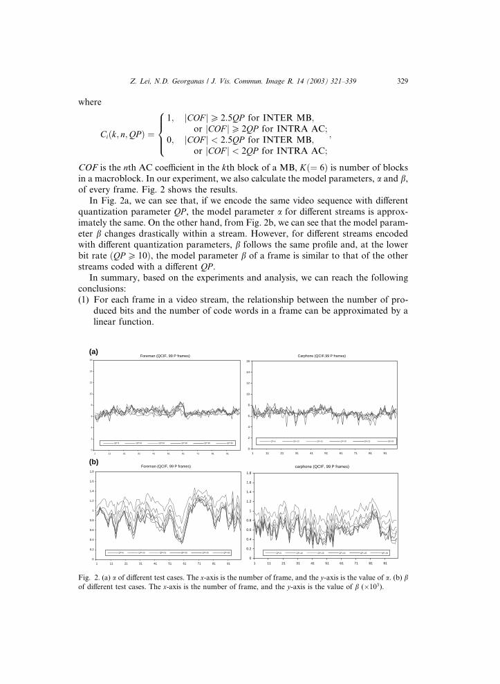
in a macroblock. In our experiment, we also calculate the model parameters, a and b,of every frame. Fig. 2 shows the results.
In Fig. 2a, we can see that, if we encode the same video sequence with different
quantization parameter QP , the model parameter a for different streams is approx-
imately the same. On the other hand, from Fig. 2b, we can see that the model param-
eter b changes drastically within a stream. However, for different streams encodedwith different quantization parameters, b follows the same profile and, at the lower
bit rate ðQP P 10Þ, the model parameter b of a frame is similar to that of the other
streams coded with a different QP .In summary, based on the experiments and analysis, we can reach the following
conclusions:
(1) For each frame in a video stream, the relationship between the number of pro-
duced bits and the number of code words in a frame can be approximated by a
linear function.
Foreman (QCIF, 99 P frames)
11 21 31 41 51 61 71 81 91
QP=5 QP=10 QP=15 QP=20 QP=25 QP=30
Carphone (QCIF,99 P frames)
0
2
4
6
8
10
12
14
16
1 11 21 31 41 51 61 71 81 91
QP=5 QP=10 QP=15 QP=20 QP=25 QP=30
Foreman (QCIF, 99 P frames)
11 21 31 41 51 61 71 81 91
QP=5 QP=10 QP=15 QP=20 QP=25 QP=30
carphone (QCIF, 99 P frames)
0
0.2
0.4
0.6
0.8
1
1.2
1.4
1.6
1.8
1 11 21 31 41 51 61 71 81 91
QP=5 QP=10 QP=15 QP=20 QP=25 QP=30
. (a) a of different test cases. The x-axis is the number of frame, and the y-axis is the value of a. (b) brent test cases. The x-axis is the number of frame, and the y-axis is the value of b (103).

330 Z. Lei, N.D. Georganas / J. Vis. Commun. Image R. 14 (2003) 321–339
(2) When encoding the same video sequence with different quantization
parameters, the model parameter a for different streams is approximately the
same.
(3) When encoding the same video sequence with different quantization parameters,
the model parameter b for different streams is different. At the lower bit rate, b ofthe same frame in different streams have a similar value.
Based on these results, the produced bits for encoding a frame can be estimated
from the number of code words in this frame. For the same video, the model
parameters from the incoming video stream can be reused for the transcoder bit
allocation and rate control. The detailed scheme is described in the following
section.
3. Adaptive bit rate control scheme
An efficient transcoder should be able to reuse as much information from the in-
coming video as possible. Such information includes motion vectors, modes of mac-
roblocks, and other syntax information. Based on analysis in the above section, we
believe that the model parameters, a and b, from the incoming video stream can be
reused to control the output bit rate of the video transcoder. In the video transcoder,
after decoding an incoming video frame, we know the number of bits that are usedfor encoding the whole frame, B, and bits that are used for encoding frame header
information, code words, motion vectors, and other syntax information. In this
work, what we are interested in is the number of code words, C, and the number
of bits for encoding these coefficients, B̂B. Then we can calculate the model parame-
ters, a and b, of an incoming frame as
a ¼ B̂BC¼ B� b
C: ð7Þ
Based on our analysis in the previous section, we know that a is independent of
the quantization parameters. Therefore, during the encoding phase, parameter afrom the incoming video stream can be reused as a reference to estimate the
produced bit count of every frame. In order to estimate the produced bit count
by using Eq. (5), we have to know the number of code words for every possible
quantization parameter, fCiðQPiÞ; 06 i6N � 1; l6QPi 6 31g, where i is the mac-
roblock index, QPi is the quantization parameter, and N is the number of mac-
roblocks within a frame. According to Eq. (6), after transcoding and obtaining anew set of DCT coefficients, we can analyze the DCT coefficients and get the
table of CiðQPiÞ.Let CðQPÞ be the total number of code words for a frame, i.e., CðQP Þ ¼PN�1
i¼0 CiðQPÞ, and B and Bi ði ¼ 0; 1; . . . ;N � 1Þ the target bit number to be allo-
cated to a frame and the ith Macroblock respectively. If we use the same frame layer
rate control scheme as TMN-8, B is determined by the target bitrate R, the target
frame rate F , and the buffer fullness B ¼ R=F � D (Corbera and Lei, 1997), and Bi
is adaptively determined in each macroblock. The goal of bit rate control is to match
Z. Lei, N.D. Georganas / J. Vis. Commun. Image R. 14 (2003) 321–339 331
the sum of Bi to B. From the incoming video stream, we can get the average a as in
Eq. (7). Here, we first assume that we can know the total bit count, b, for encodingthe overhead information of the output frame. Actually, this information can only be
obtained after encoding the whole frame. In a later part, we will introduce a heuristic
method for estimating b. We define B̂B as the bit target for encoding the total codewords in a frame, i.e.
B̂B ¼ B� Bheader � b N ; ð8Þ
where Bheader is the number of bits for encoding the picture header, which can beknown before encoding a frame, b is the average bit number for encoding the
overhead information in a macroblock and N is the total number of macroblocks in
a frame.
Then, initially, we can estimate the total number of the code words in the output
frame by:
CðQPÞ ¼ B̂Ba: ð9Þ
By searching the table fCiðQPiÞg, we can get a reference quantization parameter QPrefas
QPref ¼ argminjCðQPiÞ � CðQP Þj ð10Þ
and the reference code words number of the output video frame CðQPrefÞ asCðQPrefÞ ¼XN�1
i¼0
CiðQPrefÞ: ð11Þ
QPref is used as the reference quantization parameter for the frame and is a syntax
element in the frame header. QPref is also used for encoding the first macroblock.
After encoding the ith macroblock, we can know the produced bit number, B̂Bi, for
encoding the code words, Ci, in this macroblock. Then we can calculate the bit
budget for encoding the remaining macroblocks, B̂BRiþ1, as
B̂BRiþ1 ¼ B̂BR
i � B̂Bi; i ¼ 0; . . . ;N � 1; B̂BR0 ¼ B̂B: ð12Þ
If we define B̂Bpi as the total produced bits for encoding the code words in the previous
i macroblocks, and Cpi as the number of code words in the previous i macroblocks,
we can update the model parameter, aiþ1, for the remaining macroblocks as
aiþ1 ¼B̂Bpi
Cpi; ð13Þ
where B̂Bpi ¼ B̂Bp
i�1 þ B̂Bi, B̂Bp0 ¼ 0, Cp
i ¼ Cpi�1 þ Ci, C
p0 ¼ 0, a0 ¼ a i ¼ 0; . . . ;N � 1.
Then the estimated number of code words in the remaining macroblocks, CRiþ1,
can be calculated as
CRiþ1 ¼
B̂BRiþ1
aiþ1
: ð14Þ

332 Z. Lei, N.D. Georganas / J. Vis. Commun. Image R. 14 (2003) 321–339
Using a similar method as in Eqs. (10) and (11), we can calculate QPiþ1 for encoding
the ðiþ 1Þth macroblock as
QPiþ1 ¼ argminjCðQPrÞ � CRiþ1j; r ¼ iþ 1; . . . ;N : ð15Þ
After selecting the QPiþ1, the ðiþ 1Þth macroblock will be quantized and entropy
coded.
In this scheme, the quantization parameter QPi is only determined by the bit
allocation algorithm. However, in order to keep a smooth video quality, the
H.263+ standard requires that the difference between quantization parameters
for two successive macroblocks not be greater than 2 (ITU-T, 1998), i.e., jQPiþ1 �QPij6 2, 06 i6N � 1. Therefore, if the difference between the quantization parame-
ter obtained from Eq. (15) and the previous quantization parameter is greater than 2,the new quantization parameter has to be adjusted. This constraint can also help us
save some computational cost. After encoding a macroblock with quantization pa-
rameterQPi, the quantization parameter for encoding the next macroblock could only
be in fQPi�2;QPi�1;QPi;QPiþ1QPiþ2g, so, in Eq. (15), we do not have to search the
number of the non-zero coefficients for the other quantization parameters. In this
scheme, after encoding every macroblock, we adaptively update the model parameter
a according to the statistical information from previous encoded macroblocks to
ensure the linear relationship between the bit budget and number of code wordsfor the remaining macroblocks, which makes the produced bits meet the bit budget
accurately.
In the above analysis, we assume that, before encoding a frame, we already know
the produced bits, b, for encoding the overhead information, which includes frame
header, motion vectors, DC coefficients, and other macroblock-layer syntax infor-
mation. However, b can only be known after encoding the whole frame. For exam-
ple, in the H.263+ basic option, if the quantization parameter of a macroblock is
different from that of the previous macroblock, there is a 5-bit penalty for changingthe quantization parameter. Specifically, 2 bits are used in the syntax element
DQUANT to indicate the difference between the values of two quantization param-
eters, and three additional bits are needed on average in the syntax elementMCBPC
to indicate that the value of QP in the current macroblock is different from that in the
previous macroblock (Corbera and Lei, 1999). In this case, before getting the quan-
tization parameter, QP , for the macroblock, we cannot know if a DQUANT field is
required in the macroblock header. At a high bit rate (smaller QP ), the amount of bis only a small part of the total bit budget, but at a lower bit rate (larger QP), b is asignificant part of total bit budget. For example, in our experiments, if we set the tar-
get bit rate to 20 kbps, frame rate to 10 frame/s, then the bit budget for encoding
every P frame is about 2000 bits. After encoding, the average b is about 1000 bits,
which is half of the total bit budget. Therefore, estimation of b has a significant effect
on the bit allocation. In this work, we propose a heuristic method to estimate the
model parameter b. Based on the analysis in the previous section, we know that,
at the lower rate, b of the same frame in different video streams has a similar value.
Therefore, we can reuse the b information from the incoming video stream. At thehigher rate, we can preassign an average value as an initial b. Before encoding a
Z. Lei, N.D. Georganas / J. Vis. Commun. Image R. 14 (2003) 321–339 333
frame, we can know the total bit number for encoding the picture header, so we only
consider b as the bit number for encoding the overhead information of the macro-
blocks in a frame. Then, before encoding a frame, we can calculate the average bof every macroblock as
b ¼ bN: ð16Þ
After encoding the ith macroblock, we can get the actual bit number of bi. We define
bPi as the total bit number for encoding the overhead information in the previous i
macroblocks, i.e.
bPi ¼ bP
i�1 þ bi; i ¼ 1; . . . ;N ; bP0 ¼ 0: ð17Þ
Then we can calculate the average bi for the previous i macroblocks as
bP
i ¼ bPi
ið18Þ
and calculate the average bi for the remaining ðN � iÞ macroblocks as
bR
i ¼ i bP
i þ ðN � iÞ bN
: ð19Þ
Finally, bR
i is used to estimate the total bit number for encoding the overhead in-formation in the remaining ðN � iÞ macroblocks as
bRi ¼ b
R
i ðN � iÞ: ð20Þ
The above procedure for the proposed bit rate control algorithm is summarized asfollows:Step 1: Decode the incoming P frame into DCT coefficients, calculate the model
parameters a and b of the frame. Perform transcoding and get the new DCT coeffi-
cients of the frame.
Step 2: Analyze the DCT coefficients of every MB and calculate the table of the
code words fCiðQPÞ; 16QP 6 31; 06 i6N � 1g as in Eq. (6); Calculate the target
bit count, B̂B, reference quantization parameter QPref , and reference code words
count, CðQPrefÞ as in Eqs. (8), (10), and (11); Calculate the average b for all macro-
blocks as in Eq. (16).Step 3: Calculate the model parameter ai, quantization parameter QPi as in Eqs.
(13) and (15). Encode the current macroblock.
Step 4: Let bi and B̂Bi be the number of bits produced for encoding overhead in-
formation and code words in the current macroblock. Update B̂BRi and b
R
i as in
Eqs. (12) and (19).
Step 5: Let i ¼ iþ 1. If i < N , go to step 3, otherwise go to step 1 for the next
frame.
In this algorithm, the model parameters, a and b, are updated after encoding ev-ery macroblock. The only extra complexity introduced is the calculation of the code
word table, fCiðQPiÞ; 06 i6N � 1; 16QPi 6 31g, by pre-analyzing the DCT coeffi-
cients. As indicated in Eq. (6), we only need to compare the absolute value of
334 Z. Lei, N.D. Georganas / J. Vis. Commun. Image R. 14 (2003) 321–339
DCT coefficients, jCOF j, to 2:5QP or < 2QP , but do not have to really quantize the
coefficients. Moreover, due to the monotonically decreasing property (for the same
DCT coefficients set in a MB, quantization with a larger QP will always have less
or equal codeword number) of quantization, the pre-analysis can be optimized in
the real implementation. When we find that the code word number at a certainQPi is zero, then, instead of calculating the code word number at other QPs that
are larger than QPi, we can directly set them to zero. Second, step 3 searches the code
word table and finds a QPi that can make the produced bits close to the bit budget.
As mentioned before, due to the constraint of the QP range in the H.263+, we only
need to search fQPi�1 � 2;QPi�1 � 1;QPi�1;QPi�1 þ 1;QPi�1 þ 2g, instead of search-
ing the whole set of quantization parameters.
4. Implementation and experimental results
The proposed rate control scheme has been implemented in a H.263+ video trans-
coder based on (TMN, 1997). Comparisons between results achieved by our rate
control method and by the TMN-8 rate control method are discussed in this section.
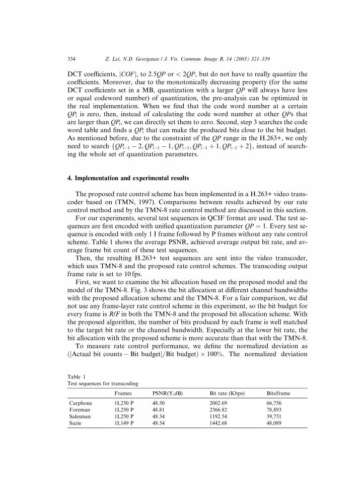
For our experiments, several test sequences in QCIF format are used. The test se-
quences are first encoded with unified quantization parameter QP ¼ 1. Every test se-
quence is encoded with only 1 I frame followed by P frames without any rate controlscheme. Table 1 shows the average PSNR, achieved average output bit rate, and av-
erage frame bit count of these test sequences.
Then, the resulting H.263+ test sequences are sent into the video transcoder,
which uses TMN-8 and the proposed rate control schemes. The transcoding output
frame rate is set to 10 fps.
First, we want to examine the bit allocation based on the proposed model and the
model of the TMN-8. Fig. 3 shows the bit allocation at different channel bandwidths
with the proposed allocation scheme and the TMN-8. For a fair comparison, we didnot use any frame-layer rate control scheme in this experiment, so the bit budget for
every frame is R/F in both the TMN-8 and the proposed bit allocation scheme. With
the proposed algorithm, the number of bits produced by each frame is well matched
to the target bit rate or the channel bandwidth. Especially at the lower bit rate, the
bit allocation with the proposed scheme is more accurate than that with the TMN-8.
To measure rate control performance, we define the normalized deviation as
ðjActual bit counts� Bit budgetj=Bit budgetÞ 100%. The normalized deviation
Table 1
Test sequences for transcoding
Frames PSNR(Y,dB) Bit rate (Kbps) Bits/frame
Carphone 1I,250 P 48.50 2002.69 66,756
Foreman 1I,250 P 48.81 2366.82 78,893
Salesman 1I,250 P 48.34 1192.54 39,751
Suzie 1I,149 P 48.54 1442.68 48,089
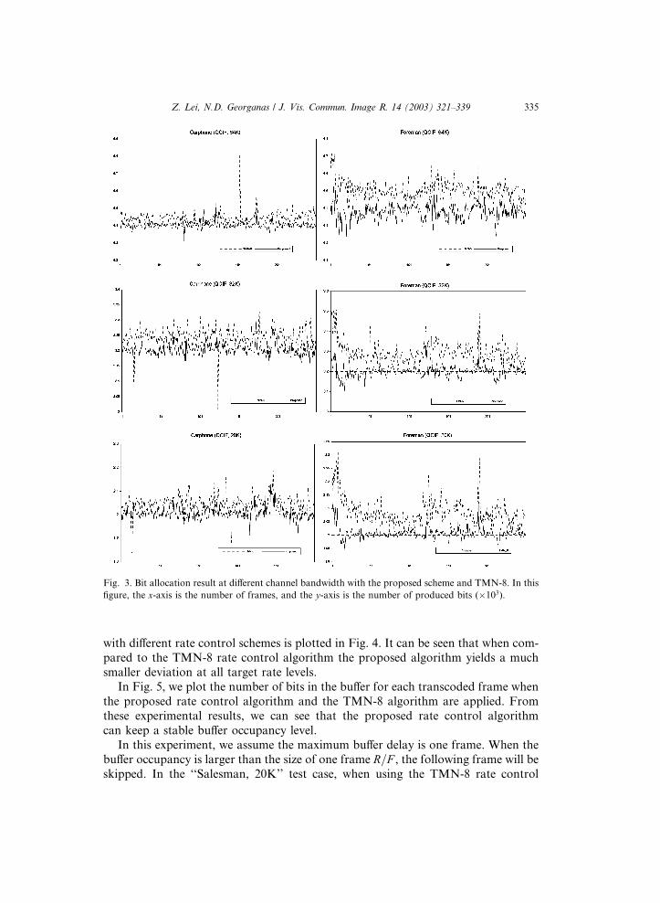
Fig. 3. Bit allocation result at different channel bandwidth with the proposed scheme and TMN-8. In this
figure, the x-axis is the number of frames, and the y-axis is the number of produced bits (103).
Z. Lei, N.D. Georganas / J. Vis. Commun. Image R. 14 (2003) 321–339 335
with different rate control schemes is plotted in Fig. 4. It can be seen that when com-
pared to the TMN-8 rate control algorithm the proposed algorithm yields a much
smaller deviation at all target rate levels.
In Fig. 5, we plot the number of bits in the buffer for each transcoded frame when
the proposed rate control algorithm and the TMN-8 algorithm are applied. From
these experimental results, we can see that the proposed rate control algorithm
can keep a stable buffer occupancy level.
In this experiment, we assume the maximum buffer delay is one frame. When thebuffer occupancy is larger than the size of one frame R=F , the following frame will be
skipped. In the ‘‘Salesman, 20K’’ test case, when using the TMN-8 rate control
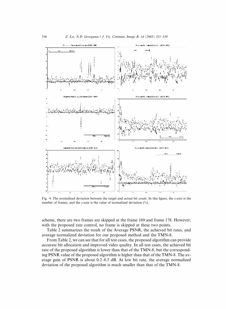
Fig. 4. The normalized deviation between the target and actual bit count. In this figure, the x-axis is thenumber of frames, and the y-axis is the value of normalized deviation (%).
336 Z. Lei, N.D. Georganas / J. Vis. Commun. Image R. 14 (2003) 321–339
scheme, there are two frames are skipped at the frame 169 and frame 178. However,
with the proposed rate control, no frame is skipped at these two points.
Table 2 summarizes the result of the Average PSNR, the achieved bit rates, and
average normalized deviation for our proposed method and the TMN-8.
From Table 2, we can see that for all test cases, the proposed algorithm can provide
accurate bit allocation and improved video quality. In all test cases, the achieved bitrate of the proposed algorithm is lower than that of the TMN-8, but the correspond-
ing PSNR value of the proposed algorithm is higher than that of the TMN-8. The av-
erage gain of PSNR is about 0.2–0.5 dB. At low bit rate, the average normalized
deviation of the proposed algorithm is much smaller than that of the TMN-8.
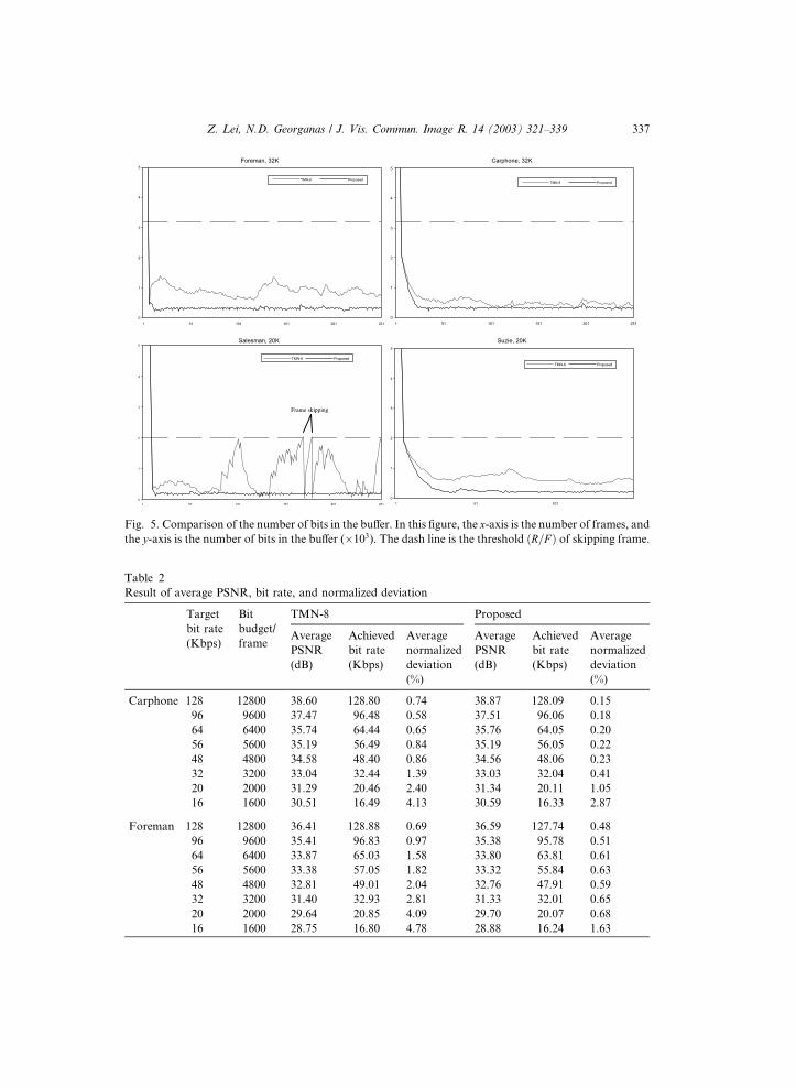
Fig. 5. Comparison of the number of bits in the buffer. In this figure, the x-axis is the number of frames, and
the y-axis is the number of bits in the buffer (103). The dash line is the threshold ðR=F Þ of skipping frame.
Table 2
Result of average PSNR, bit rate, and normalized deviation
Target
bit rate
(Kbps)
Bit
budget/
frame
TMN-8 Proposed
Average
PSNR
(dB)
Achieved
bit rate
(Kbps)
Average
normalized
deviation
(%)
Average
PSNR
(dB)
Achieved
bit rate
(Kbps)
Average
normalized
deviation
(%)
Carphone 128 12800 38.60 128.80 0.74 38.87 128.09 0.15
96 9600 37.47 96.48 0.58 37.51 96.06 0.18
64 6400 35.74 64.44 0.65 35.76 64.05 0.20
56 5600 35.19 56.49 0.84 35.19 56.05 0.22
48 4800 34.58 48.40 0.86 34.56 48.06 0.23
32 3200 33.04 32.44 1.39 33.03 32.04 0.41
20 2000 31.29 20.46 2.40 31.34 20.11 1.05
16 1600 30.51 16.49 4.13 30.59 16.33 2.87
Foreman 128 12800 36.41 128.88 0.69 36.59 127.74 0.48
96 9600 35.41 96.83 0.97 35.38 95.78 0.51
64 6400 33.87 65.03 1.58 33.80 63.81 0.61
56 5600 33.38 57.05 1.82 33.32 55.84 0.63
48 4800 32.81 49.01 2.04 32.76 47.91 0.59
32 3200 31.40 32.93 2.81 31.33 32.01 0.65
20 2000 29.64 20.85 4.09 29.70 20.07 0.68
16 1600 28.75 16.80 4.78 28.88 16.24 1.63
Z. Lei, N.D. Georganas / J. Vis. Commun. Image R. 14 (2003) 321–339 337
338 Z. Lei, N.D. Georganas / J. Vis. Commun. Image R. 14 (2003) 321–339
5. Conclusions
In this paper, we proposed a novel bit rate control scheme with self-adaptation
ability for video transcoding. Different from the current existing rate control
schemes, the proposed scheme requires the number of code words in a frame, thusoperating totally in the compressed domain. Based on this bit production model,
a simple but accurate bit allocation and rate control algorithm is proposed and im-
plemented. The experimental results show that this scheme can accurately allocate
the bit budget to every macroblock in a frame. Compared to TMN-8, the proposed
scheme can allocate the bit budget more accurately to the macroblocks in a frame
and generate a more stable video stream. In addition, at the same bit rate target, vi-
deo streams produced by the proposed algorithm have better quality than that pro-
duced by the TMN-8. The proposed rate control scheme can be used in videotranscoders to generate different bit-rate video streams for transmission over heter-
ogeneous networks.
References
Assunc�~aao, P., Ghanbri, M., 1996. Post-processing of MPEG-2 coded video for transmission at lower bit
rates. In: Proc. IEEE Internat. Conf. on Acoustics, Speech, and Signal Processing, ICASSP�96, vol. 4,pp. 1998–2001.
Chang, S.-F., Messerschmitt, D.G., 1993. A new approach to decoding and composting motion
compensated DCT-based images. In: Proc. IEEE Internat. Conf. on Acoustics, Speech, and Signal
Processing, ICASSP�93, vol. 5, pp. 421–424.Cheng, J.-B., Hang, H.-M., 1997. Adaptive piecewise linear bits estimation model for MPEG based video
coding. Journal of Visual Communication and Image Representation 8 (1), 51–67, doi:10.1006/
jvci.1997.0329.
Chiang, T., Zhang, Y.-Q., 1997. A new rate control scheme using quadratic rate distortion model. IEEE
Transactions on Circuits and Systems for Video Technology 7 (1), 246–250.
Choi, J., Park, D., 1994. A stable feedback control of the buffer state using the controlled langrange
multiplier method. IEEE Transaction on Image Processing 3, 546–558.
Corbera, J.R., Lei, S., 1997. Rate Control for Low Delay Video Communications, ITU-Telecommuni-
cations Standardization Sector, Video Coding Experts Group, Document Q15-A-20, Portland, June
24–27.
Corbera, J.R., Lei, S., 1999. Rate control in DCT video coding for low-delay communications. IEEE
Transaction on Circuit and System for Video Technology 9 (1).
Ding, W., Liu, B., 1996. Rate control of MPEG video coding and recording by rate-quantization
modeling. IEEE Transactions on Circuits and Systems for Video Technology 6 (1), 12–20.
Ghanbari, M., 1999. Video Coding: An Introduction to Standard Codecs. Institution of Electrical
Engineering Press, London.
Hang, H.-M., Chen, J.-J., 1997. Source model for transform video coder and its application – Part I:
fundamental theory. IEEE Transactions on Circuits and System for Video technology 7 (2), 287–298.
He, Z., Kim, Y.K., Mitra, S.K., 2001. Low-delay rate control for DCT video coding via q – domain source
modeling. IEEE Transaction on Circuits and Systems for Video Technology 11 (8).
Hoang, D.T., Vitter, J.S., 2001. Efficient Algorithms for MPEG Video Compression. Wiley–Interscience,
New York.
ITU-T, 1998. Draft H.263, Video Coding for Low Bit Rate Communication, January 27.
Lee J., Dickinson B.W., 1994. Joint optimization of frame type selection and bit allocation for MPEG
video encoders. In: Proc. Internat. Conf. on Image Processing �94, vol. II, Austin, TX, pp. 962–966.
Z. Lei, N.D. Georganas / J. Vis. Commun. Image R. 14 (2003) 321–339 339
Lin, L.-J., Ortega, A., 1998. Bit-rate control using piecewise approximated rate–distortion characteristics.
IEEE Transactions on Circuit and Systems for Video Technology 8 (4), 446–459.
Lin, D.W., Wang, M.-H., Chen J.-J., 1993. Optimal delayed-coding of video sequences subject to a buffer-
size constraint. In: Proc. SPIE Visual Communication and Image Processing �93, Cambridge, MA,
November, pp. 223–234.
Ortega, A., Ramchandran, K., Vetterli, M., 1994. Optimal Trellis-based buffered compression and fast
approximations. IEEE Transaction on Image Processing 3, 26–40.
Pao, I.-M., Sun, M.-T., 2001. Encoding DCT coefficients based on rate–distortion measurement. Journal
of Visual Communication and Image Representation 12, 29–43, doi:10.1006/jvci.2000.0461.
Puri, A., Aravind, R., 1991. Motion-compensated video coding with adaptive perceptual quantization.
IEEE Transaction on Circuits and Systems foe Video Technology 1, 351–361.
Ramchandran, K., Ortega, A., Vetterli, M., 1994. Bit allocation for dependent quantization with
application to multiresolutions and MPEG video coders. IEEE Transaction on Image Processing 2.
Sun, H., Kwok, W., Zdopski, J.W., 1996. Architecture for MPEG compressed bitstream scaling. IEEE
Transactions on Circuits and Systems for Video Technology 6, 191–199.
Tao, B., Dickinson, B.W., Peterson, H.A., 2000. Adaptive model-driven bit allocation for MPEG video
coding. IEEE Transactions on Circuits and Systems for Video Technology 10 (1), 147–157.
TMN, 1997. Version 3.0, Department of Electrical Engineering, University of British Columbia, Canada,
May 27.
Wu, S.-W., Gersho, A., 1991. Rate-constrained optimal block-adaptive coding for digital tape recording of
HDTV. IEEE Transactions on Circuits and Systems for Video Technology 1, 100–112.
Yang, Y., Hemami, S.S., 2000. Generalized rate–distortion optimization for motion-compensated video
coders. IEEE Transactions on Circuits and Systems for Video Technology 10 (6).
Youn, J., Sun, M.-T., 2000. Video transcoding with H.263 bit-streams. Journal of Visual Communication
and Image Representation 11, 385–403, doi:10.1006/jvci.2000.0449.
Zhu, Q.-F., Keofsky, L., Garrison, M.B., 1999. Low-delay, low-complexity rate reduction and continuous
presence for multipoint videoconferencing. IEEE Transactions on Circuits and Systems for Video
Technology 9 (4), 666–676.