Embed Size (px)
Citation preview
Application Note #3 (Rev. a)
Using PatchTool for IDEAlliance PRINTER proofing certification
1. Introduction
1.1. What is IDEAlliance?
Formed in 1996 and originally called the Graphics Communication Association, IDEAlliance, which stands for International Digital Enterprise Alliance, is a membership organization dedicated to the digital imaging, printing, and publishing fields. It develops technical specifications and processes, and promotes them through seminars, trade shows and publications. IDEAlliance is separated in working groups and committees. Among those, the Print Properties Working Group is responsible for developing specifications for the print industry; these specifications include the G7 process and the off-press and monitor proofing systems. The GRACoL (General Requirements and Applications for Commercial Offset Lithography) committee maintains guidelines for commercial printing and was particularly involved with the Print Properties Working Group in developing the characterization data for coated #1 paper on sheetfed offset presses. Formed informally in 1974 by a group of concerned industry experts, SWOP (Specifications for Web Offset Publications) first published a specification for web printing of publications in 1986. It merged with IDEAlliance in 2005, where it stands as a committee. The SWOP committee, also in conjunction with the Print Properties Working Group, has recently completed characterization data sets for two grades of paper dedicated for web offset, grade #3 (such as Fortune Gloss), and grade #5 (groundwood).
http://www.idealliance.org http://www.gracol.org http://www.swop.org Other constituents of IDEAlliance include the GRACoL Network organization and the DISC (Digital Image Submission Criteria) Working Group
1.2. What is IDEAlliance proofing certification?
Proofing certification as promoted by IDEAlliance covers two aspects of the prepress tasks: proofing printer certification and monitor certification. Printer proofing certification is making sure that one can reproduce, using a medium to large format office printer, what a final press run will look like; this is also called a hard proof, a proof print, or a match print. Monitor proofing is making sure that the colors displayed on a monitor are accurate relative to the colors printed on the press, and thus also accurate relative to those on the proofing printer. With a certified proofing printer process, one can have an assessment of what the final print will look like before going to press, thus saving time and expense. This application note covers how to use PatchTool to facilitate printer proofing certification. Of course, nothing prevents you to go through the procedures of this document to check the accuracy of your printer, even if it is not used for proofing! This application note covers how to use PatchTool to facilitate printer proofing certification. Please consult Application Note #4 for how to use PatchTool to facilitate monitor proofing certification.
AN-3a Using PatchTool for IDEAlliance PRINTER proofing certification -2-
1.3. How do I print a proof?
There are many possible workflows; two are presented here. Both are based on Photoshop CS3. The first one, which closely follows the method proposed by Adobe for printing hard proofs, has the advantage that you see the proof on your display. The second one does not show you a simulated proof on screen but is faster and more direct when you work with CMYK images. Let’s assume we want to print the IT8.7/4 target, which is the main target that needs to be measured for IDEAlliance certification. Workflow-1:
• Step-1: Open an IT8.7/4 target image defined in CMYK coordinates. Such files are most often saved in a TIFF format file but can also be found in pdf format, like the ones available with these Internet links:
- From IDEAlliance: Digital Proof Files for SWOP and GRACoL (zip package). - From NPES (National Printing Equipment Association): Tools, References & Best Practices.
When opening a pdf target in Photoshop, be sure to select the CMYK Color mode. Target files usually do not have an attached ICC profile; you should assign your press profile to the image using Photoshop’s “Edit/Assign Profile…” menu.
• Step-2: In Photoshop, choose the “View/Proof Setup/Custom…” menu and select the output conditions you want to simulate. In the dialog, the “Device to Simulate” is your press ICC profile. Select either to “Preserve CMYK Numbers” or an “Absolute Colorimetric” rendering intent; because the profile we assigned to the file in Step-1 is the same as the profile for the device to simulate, selecting one or the other option will not make a difference.
• Step-3: Choose the “File/Print…” menu. In the “Print” dialog, select “Color Management” from the pop-up menu. In the dialog Print area, select “Proof”; the profile that appears in parentheses, just beside the selection button, should be the one selected in the proof setup of Step-2.
• Step-4: In the “Color Handling” pop-up menu of the Options area, select “Photoshop Manages Colors”. In the “Printer Profile” pop-up menu, select the profile of the printer used for proofing. In the “Proof Setup” pop-up menu, select the “Current Custom Setup”. Finally, place a checkmark in the paper color and black ink options.
• Step-5: You need to configure your printer driver settings in the same setup used when you printed the profiling target used to generate this proofing printer’s ICC profile, i.e. generally with color management “Off”, but with the proper paper settings. In this case, the paper will generally be a dedicated, and often costly, proofing paper.
Workflow -2:
• Step-1: Open an IT8.7/4 target image defined in CMYK coordinates. See Step-1 of Workflow-1, above, for additional information.
• Step-2: Choose the “File/Print…” menu. In the “Print” dialog, select “Color Management” from the pop-up menu. In the dialog Print area, select “Document”; the profile that appears in parentheses, just beside the selection button, should be the profile assigned in Step-1.
• Step-3: In the “Color Handling” pop-up menu of the Options area, select “Photoshop Manages Colors”. In the “Printer Profile” pop-up menu, select the profile of the printer used for proofing. Set the “Rendering Intent” to “Absolute Colorimetric” (“Black Point Compensation” should be Off and not available).
• Step-4: You need to configure your printer driver settings in the same setup used when you printed the profiling target used to generate this proofing printer’s ICC profile, i.e. generally with color management “Off”, but with the proper paper settings. In this case, the paper will generally be a dedicated, and often costly, proofing paper.
You should now measure your printed target and compare the patches with the characterization data as described in Section 2.

AN-3a Using PatchTool for IDEAlliance PRINTER proofing certification -3-
1.4. Can I use a similar procedure with any target to check the accuracy of my printer?
Yes! This can be done by printing any target file for which you have characterization data in a device-independent color space, i.e. L*a*b* or XYZ. The simplest method is to use a target saved in L*a*b*, since the characterization data coordinates will be the same as the target image color coordinates. For a target saved in CMYK or RGB, you will also need the ICC profile of the working space, which could be either embedded in the image file or available separately. These profiles contain the information required to convert device-dependent CMYK data into device-independent color (XYZ or L*a*b*). For example, you could well use the CMYK IT8.7/4 target of the preceding section for which you could assign an official SWOP or GRACoL ICC profile, and which you would then compare with the corresponding IDEAlliance characterization data. When doing such a check, it is very likely that you will use your favorite paper, which may well contain FWA (Fluorescent Whitening Agents), which make the paper look “whiter”. Just be aware that such papers may not provide the same colorimetric accuracy as dedicated proofing papers (Note: some proofing papers also contain FWA). For a target saved in L*a*b* space:
• Step-1: Open the L*a*b* target image, most likely in TIFF format. • Step-2: In Photoshop, choose the “File/Print…” menu. In the “Print” dialog, select “Color Management”
from the pop-up menu. In the dialog Print area, select “Document”; the profile that appears in parentheses, just beside the selection button, should be Lab Color.
• Step-3: In the “Color Handling” pop-up menu of the Options area, select “Photoshop Manages Colors”. In the “Printer Profile” pop-up menu, select the profile of the printer corresponding to the actual paper in the printer. Set the “Rendering Intent” to “Absolute Colorimetric” (“Black Point Compensation” should be Off and not available).
• Step-4: You need to configure your printer driver settings in the same setup used when you printed the profiling target used to generate this proofing printer’s ICC profile, i.e. generally with color management “Off”, but with the proper paper settings.
• Step-5: Compare the measurements of your printed target with the original L*a*b* values of the target. For a target saved in CMYK or RGB:
• Step-1: Open the target image. Depending on your Photoshop preferences, you may be asked to assign a working space to the image if an ICC profile is not embedded in the file. If asked, select the profile which corresponds to the file data.
• Step-2: In Photoshop, choose the “Edit/Assign Profile…” menu. Make sure a profile is assigned to the file; if not, select the profile which corresponds to the file data.
• Step-3: Choose the “File/Print…” menu. In the “Print” dialog, select “Color Management” from the pop-up menu. In the dialog Print area, select “Document”; the profile that appears in parentheses, just beside the selection button, should be the assigned profile of Step-2.
• Step-4: In the dialog Options area, select “Photoshop Manages Colors” in the “Color Handling” pop-up menu. In the “Printer Profile” pop-up menu, select the profile of the printer corresponding to the actual paper in the printer. Set the “Rendering Intent” to “Absolute Colorimetric” (“Black Point Compensation” should be Off and not available).
• Step-5: You need to configure your printer driver settings in the same setup used when you printed the profiling target used to generate this proofing printer’s ICC profile, i.e. generally with color management “Off”, but with the proper paper settings.
• Step-6: Compare the measurements of your printed target with the device-independent reference values you have for this target.
AN-3a Using PatchTool for IDEAlliance PRINTER proofing certification -4-
1.5. How does this certification fit with the G7 process?
In the recent past, and , still now, more often than not, validating a printing press was done by establishing its Tone Value Increase (TVI) curve, i.e. the dot gain, by measuring the densities of the primary inks at various percentages of ink coverage (For example: 25%, 50%, 75%, and solid). The TVI reflects how an ink spreads on the paper and is used to correct how the printing plate is manufactured. Once the densities were on target, a press was SWOP or GRACoL certified only after standard images were printed and judged by trained “certified” observers. Because of the inherent variability in human observers, IDEAlliance has developed a new validation program based essentially on measured colorimetric accuracy; it is called the G7 Proof-to-Print Process, which comprises calibration, printing, and proofing process control methods. The pre-G7 rationale was that once the individual ink densities and the TVI curves were correct, the grays should be neutral. The essential problem with this approach is that the human visual system is very sensitive to gray balance, and measuring dot gain is one step away from visual perception, which combines all ink channels in order to make gray out of it. In comparison, the G7 process first step is to obtain a perceptual linear gray ramp by matching well defined Neutral Print Density Curves (NPDC) for three-color gray and black. The individual ink densities and dot-gain curves are thus not used or required in this process, but are nonetheless considered useful as a basic press quality-control method. Of course, not everyone agrees with the concept, particularly, in Europe, and time will tell how it is accepted. In any case, the G7 process has the advantage of putting perception, or how the final product is judged by the user, as a measured specification. Once a press is validated numerically using the G7 process, it is only fitting to use similar “number-based” validation tools for monitor and printer proofing. For this reason, IDEAlliance has determined absolute colorimetric references for all the patches of the standard IT8.7/4 target; these references, called characterization data, were obtained by measuring, averaging and tweaking “ideal” reproduction obtained from real presses on three paper types. Please note that this is an ongoing process and the requirements and specification may change as users get more experience.
AN-3a Using PatchTool for IDEAlliance PRINTER proofing certification -5-
1.6. Is my home-made printer certification official?
IDEAlliance has defined a set of requirements which need to be met in order to receive their approval. In terms of color-measuring instrumentation, these requirements are:
i- The measurements shall be performed with an X-Rite DTP70 spectrophotometer. ii- The DTP70 shall be “qualified”, meaning that it should be within a certain tolerance relative to the
other instruments used by IDEAlliance to define the certification requirements. Does this mean that you cannot use another instrument, such as an iSis, an Eye-One iO, a SpectroScan, an Eye-One Pro, or any other instrument to check compliance? In a strict sense, no, but in practice, you will get a good assessment of your workflow as long as your measuring instrument is within its calibration requirements. Why will I still get useful info? Well, let’s first assume you have a DTP70 which is not qualified by IDEAlliance. This instrument will still be within the inter-instrument agreement range of all DTP70 manufactured by X-Rite. In practice, this means that you should, statistically, see a slight increase in the measured errors relative to the official IDEAlliance values. In some cases, this increase will push your measured values outside the tolerance limits set out by IDEAlliance. If the discrepancy is larger than the inter-instrument agreement value (stated as 0,5 ΔE* max., CIE94), then you have a good hint that your process would not be certifiable. If the error is less than the inter-instrument value, then you have a pretty good system which could likely pass official certification. If using an instrument other than the DTP70, the difference between your measurements and those made with a “qualified” unit is likely to be higher than what it would be if you used the certified instrument. By how much? This is hard to nail down since most manufacturers specify inter-instrument accuracy (of the same brand and model), and never specify “absolute” accuracy. It could well happen that your process accuracy is so good that the errors are still within the requirements. It could also happen that the proofing printer is off in one direction and that the measuring instrument is off in the other direction, thus cancelling each other, but this is not highly probable. The advantages of doing this certification check yourself are:
i- To better understand the certification process while improving your system’s performance. ii- To increase confidence when seeking official certification, and minimize the associated cost. iii- To be able to regularly check if your proofing printer is stable and within its requirements.

AN-3a Using PatchTool for IDEAlliance PRINTER proofing certification -6-
2. Using PatchTool for printer proofing certification The certification is obtained by comparing a standard IT8.7/4 printed target against IDEAlliance reference data, and by checking the repeatability of color control strips. The reference data is available for three paper types:
i- GRACoL Commercial, Grade 1, Coated (Ex.: Luster Gloss) ii- SWOP High End Publication, Grade 3, Coated (Ex.: Fortune Gloss) iii- SWOP Publication, Grade 5, Coated (Ex.: Montery Gloss)
The characterization files are available in the “IDEAlliance_files” folder located within the PatchTool application folder (As a shortcut, use the “File/Open Sample Files/IDEAlliance Files…” menu). These files, as well as IT8.7/4 target images, can also be downloaded from the IDEAlliance Web site. The printer proofing requirements are (PROOFING CERTIFICATION PROCESS_v16.pdf ):
Criteria Requirement 1 Must pass the general measurement requirements of ISO 12647-7 YES
2 Proofs will be measured against a white background as per CGATS.5-2004 (opaque; diffuse reflecting; CIELAB L* > 92; CIELAB C* ≤ 3.0; non-fluorescing)
YES
3 Color-difference formula CIELAB (Delta-E*ab) 4.1 Average of all patches Average ΔE ≤ 1.5 4.2 95th percentile Maximum ΔE ≤ 6.0 4.3 Solid CMY patches ΔE ≤ 5.0 4 IT8.7/4 4.4 Overprint RGB patches ΔE ≤ 5.0 4.5 50/40/40 Gray patch ΔE ≤ 1.5 4.6 Paper White L* -2.0 ≤ ΔL* ≤ 2.0 (excluding a* -1.0 ≤ Δa* ≤ 1.0 fluorescence) b* -2.0 ≤ Δb* ≤ 2.0
5 ISO 12647-7 2007 Control Strip Color-difference for each
patch between pages should be ΔE ≤ 1.5
ISO 12647-7 (Graphic technology — Process control for the production of half-tone colour separations, proof and production prints — Part 7: Proofing processes working directly from digital data) covers practical printing requirements such as file format, proof paper stability to aging and light, colorant rub resistance, margin information, control strip layout, etc. The 95th percentile criteria of the IT8.7/4 target means that 95% of the patches shall have a color difference of less than 6.0. Of course, the criteria for the solid and overprint patches, the 50/40/40 gray and the white paper must also be met, which means that these patches will also be within the 95th percentile. The ISO 12647-7 Control Strip is printed on each page of the IDEAlliance proofing form. The form, shown on the next page, is designed to be printed on two pages but may require more pages for smaller paper sizes. The first page contains the IT8.7/4 and other specialized targets used for numerical analysis; the second page has images dedicated to visual assessment. For printer proofing certification, the ISO control strip is not compared against a reference, but to the strip(s) printed on the other page(s). As specified by IDEAlliance, if a requirement is not met, the proof can be re-read and, if it fails again, a second set of proofs can be read.

AN-3a Using PatchTool for IDEAlliance PRINTER proofing certification -7-
To check the certification requirements, you only need to measure the IT8.7/4 target and the two ISO 12647-7 Control Strips from the above form. This means that you could print just the target and the control strips if you do not have the space to print the entire form. Ideally, the control strips should be placed on different pages of the press run; however, you could place two copies of the strip on the same page, above and below the IT8.7/4 target for instance. You could also simplify the procedure even more and print only the IT8.7/4 target. The next two sections look at how PatchTool can be used to analyze the IT8.7/4 target and the ISO 12647-7 Control Strip data.
IDEAlliance Proofing Form (Page 1 - Numerical)
IDEAlliance Proofing Form(Page 2 - Visual)
IT8.7/4 Target ISO 12647-7 Control StripNominal page size:17 inch x 21 inch
(43,2 cm x 53,3 cm)
AN-3a Using PatchTool for IDEAlliance PRINTER proofing certification -8-
2.1. Printer proofing certification procedure (IT8.7/4 target)
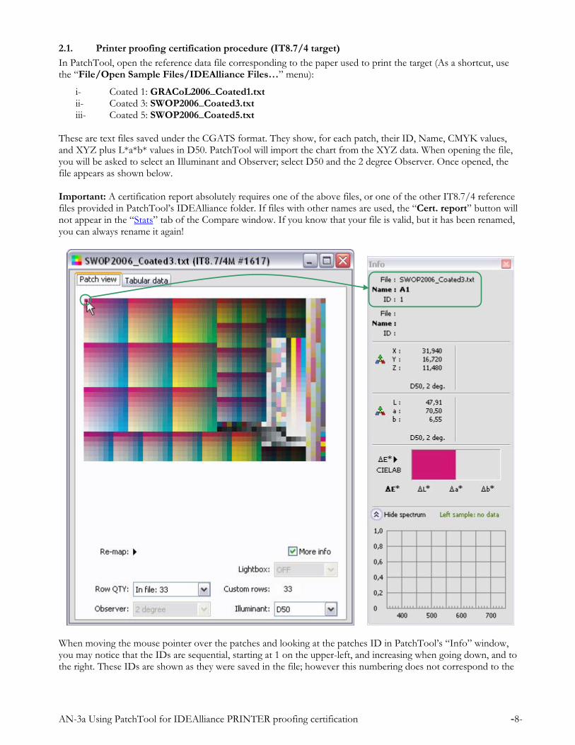
In PatchTool, open the reference data file corresponding to the paper used to print the target (As a shortcut, use the “File/Open Sample Files/IDEAlliance Files…” menu):
i- Coated 1: GRACoL2006_Coated1.txt ii- Coated 3: SWOP2006_Coated3.txt iii- Coated 5: SWOP2006_Coated5.txt
These are text files saved under the CGATS format. They show, for each patch, their ID, Name, CMYK values, and XYZ plus L*a*b* values in D50. PatchTool will import the chart from the XYZ data. When opening the file, you will be asked to select an Illuminant and Observer; select D50 and the 2 degree Observer. Once opened, the file appears as shown below. Important: A certification report absolutely requires one of the above files, or one of the other IT8.7/4 reference files provided in PatchTool’s IDEAlliance folder. If files with other names are used, the “Cert. report” button will not appear in the “Stats” tab of the Compare window. If you know that your file is valid, but it has been renamed, you can always rename it again!
When moving the mouse pointer over the patches and looking at the patches ID in PatchTool’s “Info” window, you may notice that the IDs are sequential, starting at 1 on the upper-left, and increasing when going down, and to the right. These IDs are shown as they were saved in the file; however this numbering does not correspond to the

AN-3a Using PatchTool for IDEAlliance PRINTER proofing certification -9-
standard IT8.7/4 IDs for this layout. This is not a problem as we can easily assign the IDs using the “Re-map” menu, as shown here:
This re-assignment is important if you want, or need, to change the target layout, and is required by PatchTool in order to identify specific patches when generating the certification report. In the example above, we know that we have the visual layout and we thus assign the IDs for this layout. Once the IDs are assigned, you can easily switch between the random and visual layout using the “Re-map” menu. Now open your measurement file with PatchTool. The layout may or may not be identical to the reference layout. Use the “Re-map” menu to assign the IDs, if required, and to change the layout so that the measured file is in the same layout as the reference file. Please note that if your “Measured” layout is neither “Visual” nor “Random”, it is still possible to change it to “Visual”, using the “Re-map” menu, if the IDs were properly assigned by the application used to measure the patches. With the reference and measured files in the same layout, you can now compare each patch in the reference file with its corresponding patch in the measured file. First click on a given patch in the reference window, to freeze the patch info in the “Info” window, and then move the mouse to the measured file window; the difference between the frozen patch and the patch under the mouse pointer is shown in the Info window. A faster method to compare all patches is to select the “Tool/Compare…” menu. The following window appears:
AN-3a Using PatchTool for IDEAlliance PRINTER proofing certification -10-
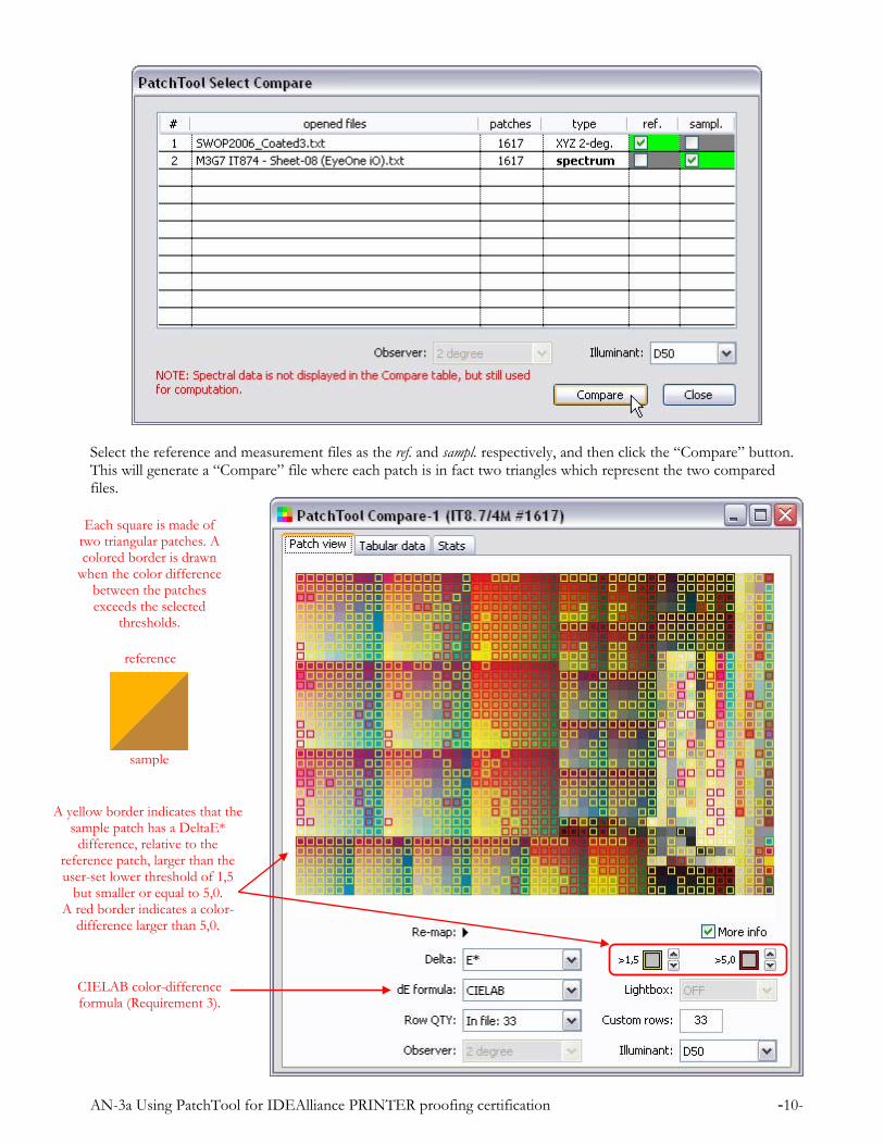
Select the reference and measurement files as the ref. and sampl. respectively, and then click the “Compare” button. This will generate a “Compare” file where each patch is in fact two triangles which represent the two compared files.
A yellow border indicates that the sample patch has a DeltaE*
difference, relative to the reference patch, larger than the user-set lower threshold of 1,5
but smaller or equal to 5,0. A red border indicates a color-
difference larger than 5,0.
Each square is made of two triangular patches. A colored border is drawn
when the color difference between the patches exceeds the selected
thresholds.
reference
sample
CIELAB color-difference formula (Requirement 3).
AN-3a Using PatchTool for IDEAlliance PRINTER proofing certification -11-
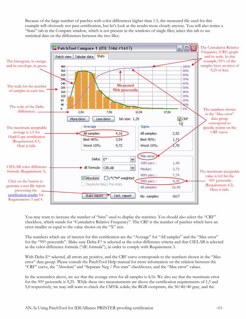
Because of the large number of patches with color differences higher than 1.5, the measured file used for this example will obviously not pass certification, but let’s look at the results more closely anyway. You will also notice a “Stats” tab in the Compare window, which is not present in the windows of single files; select this tab to see statistical data on the differences between the two files.
You may want to increase the number of “bins” used to display the statistics. You should also select the “CRF” checkbox, which stands for “Cumulative Relative Frequency”. The CRF is the number of patches which have an error smaller or equal to the value shown on the “X” axis. The numbers which are of interest for this certification are the “Average” for “All samples” and the “Max error” for the “95th percentile”. Make sure Delta-E* is selected as the color-difference criteria and that CIELAB is selected as the color-difference formula (“dE formula”), in order to comply with Requirement 3. With Delta-E* selected, all errors are positive, and the CRF curve corresponds to the numbers shown in the “Max error” data group. Please consult the PatchTool Help manual for more information on the relation between the “CRF” curve, the ”Absolute” and “Separate Neg / Pos stats” checkboxes, and the “Max error” values. In the screenshot above, we see that the average error for all samples is 4,16. We also see that the maximum error for the 95th percentile is 9,25. While these two measurements are above the certification requirements of 1,5 and 5,0 respectively, we may still want to check the CMYK solids, the RGB overprints, the 50/40/40 gray, and the
The numbers shown in the “Max error”
data group correspond to
specific points on the CRF curve.
The histogram, in orange, and its envelope, in green.
The Cumulative Relative Frequency (CRF) graph
and its scale. In this example, 95% of the
samples have an error of 9,25 or less.
The scale of the Delta differences.
The scale for the number of samples in each bin.
CIELAB color-difference formula (Requirement 3).
The maximum acceptable average is 1,5 for
Hard Copy certification (Requirement 4.1).
Here it fails.
The maximum acceptable value is 6,0 for the
95th percentile (Requirement 4.2).
Here it fails.
Measured95th percentile
Click on the button to generate a text file report
presenting the certification results for Requirements 3 and 4.

AN-3a Using PatchTool for IDEAlliance PRINTER proofing certification -12-
paper white. We can compare each patch manually or generate a report which will present all the results relative to the IT8.7/4 chart. The manual method requires selecting the “Patch view” tab and moving over each patch with the mouse, while looking at the “Info” window. The patches’ locations are shown below for the visual layout. Make sure you select the same color-difference formula for the Info window as the one selected in the file window (CIELAB), since they are selected and computed independently. To facilitate this manual inspection, it would be helpful to remove the borders on patches which exceed the error thresholds, since there are many of them in our example. We could increase the thresholds, but it is more convenient to simply click in the square which illustrates the border’s appearance; the appearance will cycle from a thin border to a thick border, then to no border, then back to a thin border. Important: Proper assignment of the IT8.7/4 patches’ ID is essential in order to obtain a valid certification report. If, before comparing the reference patches from the IDEAlliance file to the measured values, you did not re-assign the reference IDs to the ones of the IT8.7/4 Visual layout, then the patch IDs will not correspond to the numbers shown below. Nonetheless, you can still assign the IDs in the Compare window using the “Re-map” menu.
RedID 657
Blue ID 81
GreenID 721
Paper White
ID 1367
50/40/40Gray
ID 1611
Cyan – ID 1287Magenta – ID 1307 Yellow – ID 1327 Black – ID 1347
Click in each square until the error
border disappears.
AN-3a Using PatchTool for IDEAlliance PRINTER proofing certification -13-
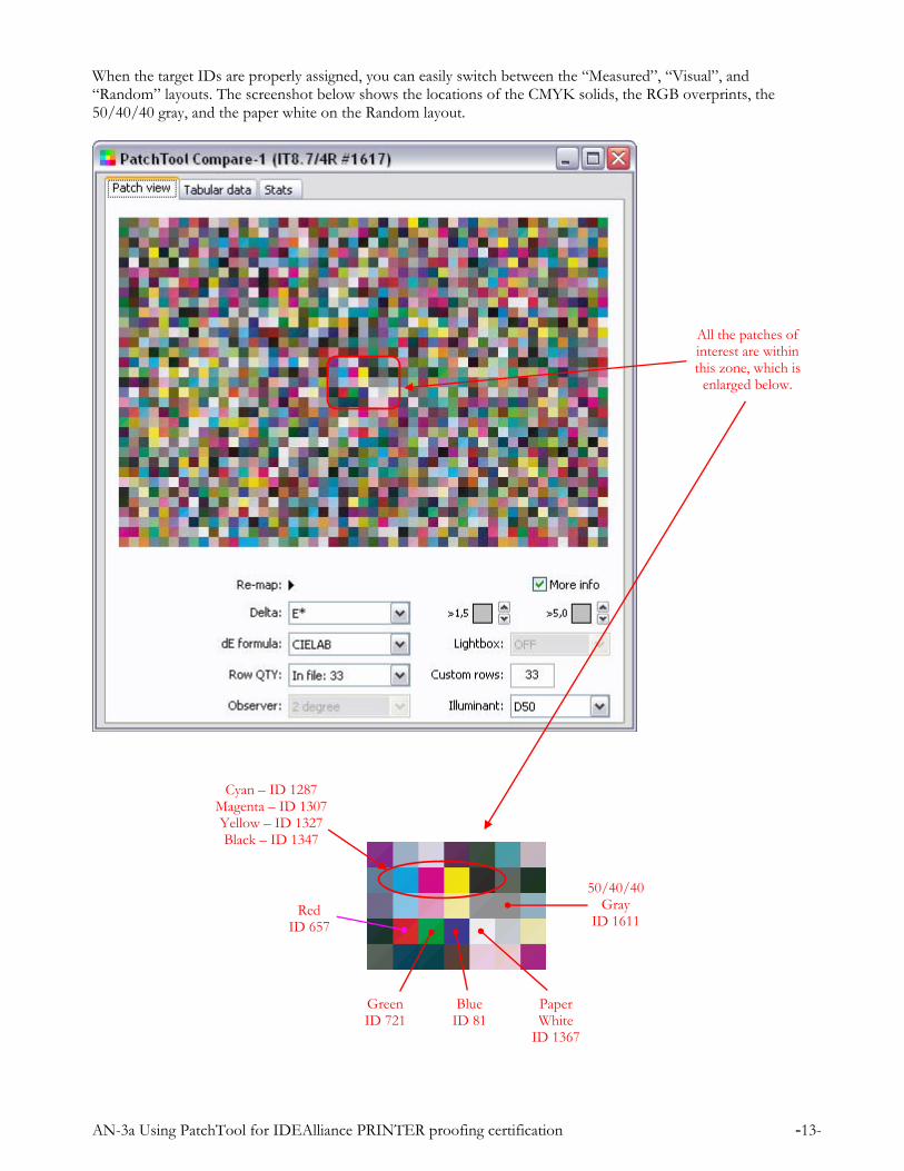
When the target IDs are properly assigned, you can easily switch between the “Measured”, “Visual”, and “Random” layouts. The screenshot below shows the locations of the CMYK solids, the RGB overprints, the 50/40/40 gray, and the paper white on the Random layout.
All the patches of interest are within this zone, which is
enlarged below.
Red ID 657
BlueID 81
GreenID 721
Paper White
ID 1367
50/40/40 Gray
ID 1611
Cyan – ID 1287 Magenta – ID 1307 Yellow – ID 1327 Black – ID 1347
AN-3a Using PatchTool for IDEAlliance PRINTER proofing certification -14-
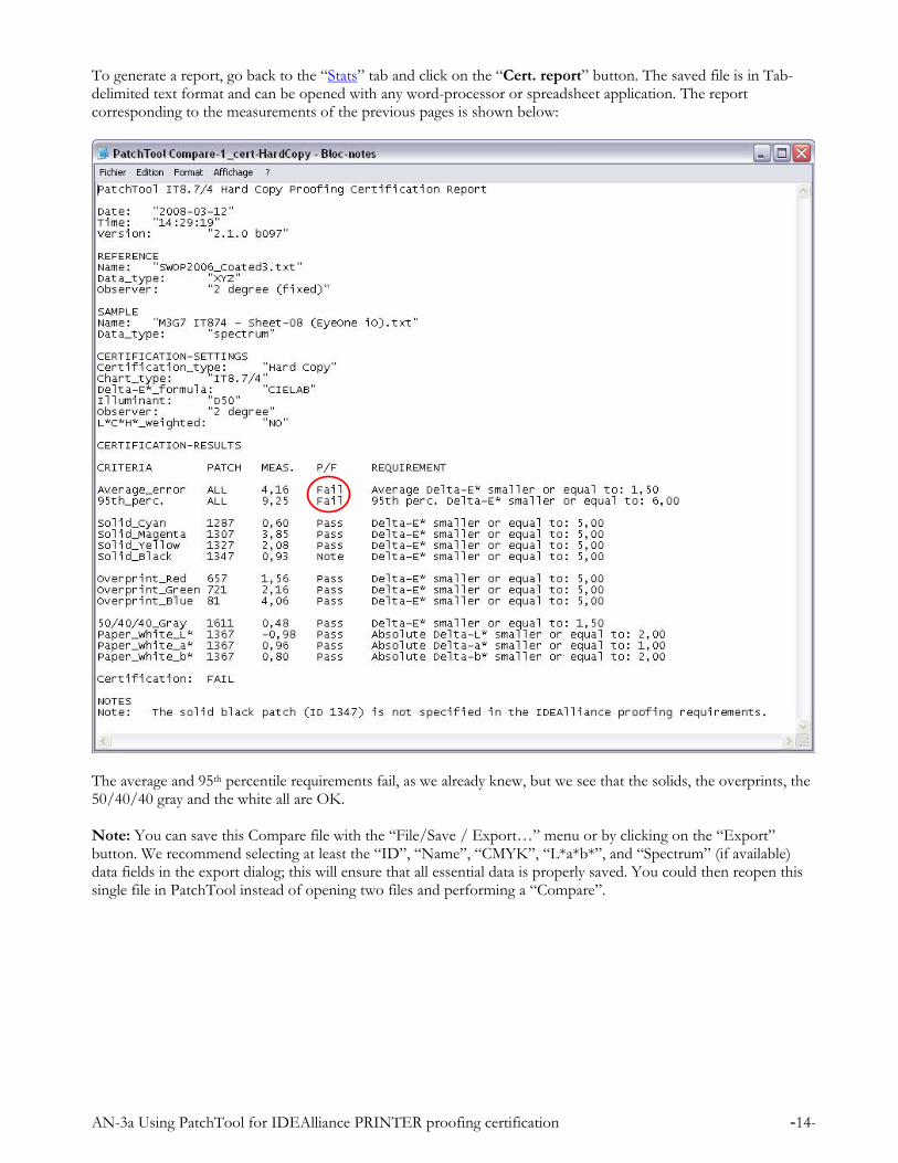
To generate a report, go back to the “Stats” tab and click on the “Cert. report” button. The saved file is in Tab-delimited text format and can be opened with any word-processor or spreadsheet application. The report corresponding to the measurements of the previous pages is shown below:
The average and 95th percentile requirements fail, as we already knew, but we see that the solids, the overprints, the 50/40/40 gray and the white all are OK. Note: You can save this Compare file with the “File/Save / Export…” menu or by clicking on the “Export” button. We recommend selecting at least the “ID”, “Name”, “CMYK”, “L*a*b*”, and “Spectrum” (if available) data fields in the export dialog; this will ensure that all essential data is properly saved. You could then reopen this single file in PatchTool instead of opening two files and performing a “Compare”.
AN-3a Using PatchTool for IDEAlliance PRINTER proofing certification -15-
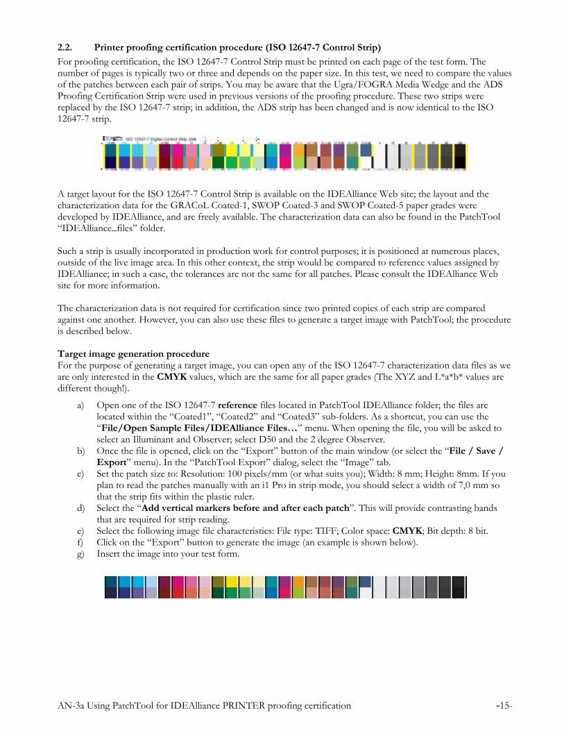
2.2. Printer proofing certification procedure (ISO 12647-7 Control Strip)
For proofing certification, the ISO 12647-7 Control Strip must be printed on each page of the test form. The number of pages is typically two or three and depends on the paper size. In this test, we need to compare the values of the patches between each pair of strips. You may be aware that the Ugra/FOGRA Media Wedge and the ADS Proofing Certification Strip were used in previous versions of the proofing procedure. These two strips were replaced by the ISO 12647-7 strip; in addition, the ADS strip has been changed and is now identical to the ISO 12647-7 strip.
A target layout for the ISO 12647-7 Control Strip is available on the IDEAlliance Web site; the layout and the characterization data for the GRACoL Coated-1, SWOP Coated-3 and SWOP Coated-5 paper grades were developed by IDEAlliance, and are freely available. The characterization data can also be found in the PatchTool “IDEAlliance_files” folder. Such a strip is usually incorporated in production work for control purposes; it is positioned at numerous places, outside of the live image area. In this other context, the strip would be compared to reference values assigned by IDEAlliance; in such a case, the tolerances are not the same for all patches. Please consult the IDEAlliance Web site for more information. The characterization data is not required for certification since two printed copies of each strip are compared against one another. However, you can also use these files to generate a target image with PatchTool; the procedure is described below. Target image generation procedure For the purpose of generating a target image, you can open any of the ISO 12647-7 characterization data files as we are only interested in the CMYK values, which are the same for all paper grades (The XYZ and L*a*b* values are different though!).
a) Open one of the ISO 12647-7 reference files located in PatchTool IDEAlliance folder; the files are located within the “Coated1”, “Coated2” and “Coated3” sub-folders. As a shortcut, you can use the “File/Open Sample Files/IDEAlliance Files…” menu. When opening the file, you will be asked to select an Illuminant and Observer; select D50 and the 2 degree Observer.
b) Once the file is opened, click on the “Export” button of the main window (or select the “File / Save / Export” menu). In the “PatchTool Export” dialog, select the “Image” tab.
c) Set the patch size to: Resolution: 100 pixels/mm (or what suits you); Width: 8 mm; Height: 8mm. If you plan to read the patches manually with an i1 Pro in strip mode, you should select a width of 7,0 mm so that the strip fits within the plastic ruler.
d) Select the “Add vertical markers before and after each patch”. This will provide contrasting bands that are required for strip reading.
e) Select the following image file characteristics: File type: TIFF; Color space: CMYK; Bit depth: 8 bit. f) Click on the “Export” button to generate the image (an example is shown below). g) Insert the image into your test form.

AN-3a Using PatchTool for IDEAlliance PRINTER proofing certification -16-
Certification check with the ISO 12647-7 Control Strip (Requirement 5) This procedure assumes that all color strips have been previously measured and that the data was saved in a file.
a) Open the two or three measurement data files. When opening the file, you may be asked to select an Illuminant and Observer; select D50 and the 2 degree Observer. There is probably no need to re-map the layout, in order to match the patches between files, since the two measurements were likely done using the same reference file.
b) Open the “PatchTool Select Compare” dialog with the “Tools/Compare…” menu. Select any measurement file as the ref. and another measurement file as the sampl. Click on the “Compare” button.
c) In the “Patch view” tab of the “Compare” window. Select Delta-E* and the CIELAB “dE formula” (This is Requirement 3). Set both error thresholds at 1,5, as shown here. With the thresholds adjusted in this way, any patch which shows a red border is not compliant, and the requirement is not met.
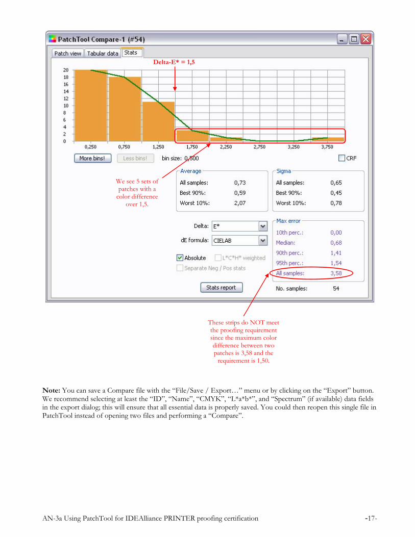
Checking compliance with these color strips is thus as easy as looking for a single “over-the-threshold” patch. The corresponding “Stats” tab screenshot is shown on the next page; if required, a report containing all the statistical data can be generated from the window by clicking on the “Stats report” button..
AN-3a Using PatchTool for IDEAlliance PRINTER proofing certification -17-
Note: You can save a Compare file with the “File/Save / Export…” menu or by clicking on the “Export” button. We recommend selecting at least the “ID”, “Name”, “CMYK”, “L*a*b*”, and “Spectrum” (if available) data fields in the export dialog; this will ensure that all essential data is properly saved. You could then reopen this single file in PatchTool instead of opening two files and performing a “Compare”.
These strips do NOT meet the proofing requirement since the maximum color difference between two patches is 3,58 and the
requirement is 1,50.
We see 5 sets of patches with a
color difference over 1,5.
Delta-E* = 1,5

AN-3a Using PatchTool for IDEAlliance PRINTER proofing certification -18-
3. Conclusion Most of the IDEAlliance requirements for certifying a proofing printer are simple, but processing the data in order to verify compliance is computer-intensive. As we have seen, PatchTool facilitates this task so that anyone can verify how their printer meets the colorimetric requirements. Of course, unless you use “qualified” measuring instruments, this verification cannot be construed as an official IDEAlliance certification, but it does provide a very good assessment of your printer’s calibration state. In addition, when performed on a regular basis, it is a simple method to track your equipment’s performance. Revision History
Rev. a (April 2009): This note now follows the requirements of Version-16 of the PROOFING CERTIFICATION PROCESS document. The ADS Proofing Certification strip and the FOGRA Media Wedge are replaced by the ISO 12647-7 Control Strip. The text was revised to correspond to PatchTool Version-2.6. The Internet links were updated.
First release (March 2008)
BabelColor is a registered trademark, and the BabelColor logo is a trademark of Danny Pascale and The BabelColor Company. “GRACoL” and “IDEAlliance” are registered trademarks of International Digital Enterprise Alliance, Inc.
“SWOP” is a registered trademark of SWOP, Inc. SWOP is a Program within IDEAlliance. All other product and company names may be trademarks of their respective owners.
© 2008-2009 Danny Pascale and The BabelColor Company
The BabelColor Company
Founded in 2003, The BabelColor Company is dedicated to the development and sale of
specialized color translation software and color tools. It also provides color consulting services for
the professional and industrial markets.
[email protected] http://www.BabelColor.com