Embed Size (px)
Citation preview
Amur- Exelon Generation
Order No. EA-12-049 RS-15-018
February 27, 2015
U.S. Nuclear Regulatory Commission ATTN: Document Control Desk Washington, DC 20555-0001
Clinton Power Station, Unit 1 Facility Operating License No. NPF-62 NRC Docket No. 50-461
Subject: Fourth Six-Month Status Report in Response to March 12, 2012 Commission Order Modifying Licenses with Regard to Requirements for Mitigation Strategies for Beyond-Design-Basis External Events (Order Number EA-12-049)
References: 1. NRC Order Number EA-12-049, "Issuance of Order to Modify Licenses with Regard to
Requirements for Mitigation Strategies for Beyond-Design-Basis External Events," dated March 12, 2012
2. NRC Interim Staff Guidance JLD-ISG-2012-01, "Compliance with Order EA-12-049, Order Modifying Licenses with Regard to Requirements for Mitigation Strategies for Beyond-Design-Basis External Events," Revision 0, dated August 29, 2012
3. NEI 12-06, "Diverse and Flexible Coping Strategies (FLEX) Implementation Guide," Revision 0, dated August 2012
4. Exelon Generation Company, LLC's Initial Status Report in Response to March 12, 2012 Commission Order Modifying Licenses with Regard to Requirements for Mitigation Strategies for Beyond-Design-Basis External Events (Order Number EA-12-049), dated October 25, 2012
5. Exelon Generation Company, LLC Overall Integrated Plan in Response to March 12, 2012 Commission Order Modifying Licenses with Regard to Requirements for Mitigation Strategies for Beyond-Design-Basis External Events (Order Number EA-12-049), dated February 28, 2013 (RS-13-019)
6. Exelon Generation Company, LLC First Six-Month Status Report in Response to March 12, 2012 Commission Order Modifying Licenses with Regard to Requirements for Mitigation Strategies for Beyond-Design-Basis External Events (Order Number EA-12-049), dated August 28, 2013 (RS-13-117)
7. Exelon Generation Company, LLC Second Six-Month Status Report in Response to March 12, 2012 Commission Order Modifying Licenses with Regard to Requirements for Mitigation Strategies for Beyond-Design-Basis External Events (Order Number EA-12-049), dated February 28, 2014 (RS-14-009)
U.S. Nuclear Regulatory Commission Integrated Plan Report to EA-12-049 February 27, 2015 Page 2
8. Exelon Generation Company, LLC Third Six-Month Status Report in Response to March 12, 2012 Commission Order Modifying Licenses with Regard to Requirements for Mitigation Strategies for Beyond-Design-Basis External Events (Order Number EA-12-049), dated August 28, 2014 (RS-14-207)
9. NRC letter to Exelon Generation Company, LLC, Clinton Power Station, Unit 1 — Interim Staff Evaluation Relating to Overall Integrated Plan in Response to Order EA-12-049 (Mitigation Strategies) (TAC No. MF0901), dated December 17, 2013
On March 12, 2012, the Nuclear Regulatory Commission ("NRC" or "Commission") issued an order (Reference 1) to Exelon Generation Company, LLC (EGC). Reference 1 was immediately effective and directs EGC to develop, implement, and maintain guidance and strategies to maintain or restore core cooling, containment, and spent fuel pool cooling capabilities in the event of a beyond-design-basis external event. Specific requirements are outlined in Attachment 2 of Reference 1.
Reference 1 required submission of an initial status report 60 days following issuance of the final interim staff guidance (Reference 2) and an overall integrated plan pursuant to Section IV, Condition C. Reference 2 endorses industry guidance document NEI 12-06, Revision 0 (Reference 3) with clarifications and exceptions identified in Reference 2. Reference 4 provided the EGC initial status report regarding mitigation strategies. Reference 5 provided the Clinton Power Station, Unit 1 overall integrated plan.
Reference 1 requires submission of a status report at six-month intervals following submittal of the overall integrated plan. Reference 3 provides direction regarding the content of the status reports. References 6, 7, and 8 provided the first, second, and third six-month status reports, respectively, pursuant to Section IV, Condition 0.2, of Reference 1 for Clinton Power Station. The purpose of this letter is to provide the fourth six-month status report pursuant to Section IV, Condition C.2, of Reference 1, that delineates progress made in implementing the requirements of Reference 1. The enclosed report provides an update of milestone accomplishments since the last status report, including any changes to the compliance method, schedule, or need for relief and the basis, if any. The enclosed report also addresses the NRC Interim Staff Evaluation Open and Confirmatory Items contained in Reference 9.
This letter contains no new regulatory commitments. If you have any questions regarding this report, please contact David P. Helker at 610-765-5525.
I declare under penalty of perjury that the foregoing is true and correct. Executed on the 27th day of February 2015.
Respectfully submitted,
Glen T. Kaegi Director - Licensing & Regulatory Affairs Exelon Generation Company, LLC
U.S. Nuclear Regulatory Commission Integrated Plan Report to EA-12-049 February 27, 2015 Page 3
Enclosure:
1. Clinton Power Station, Unit 1 Fourth Six-Month Status Report for the Implementation of Order EA-12-049, Order Modifying Licenses with Regard to Requirements for Mitigation Strategies for Beyond-Design-Basis External Events
cc: Director, Office of Nuclear Reactor Regulation NRC Regional Administrator - Region III NRC Senior Resident Inspector — Clinton Power Station, Unit 1 NRC Project Manager, NRR — Clinton Power Station, Unit 1 Ms. Jessica A. Kratchman, NRR/JLD/PMB, NRC Mr. Jack R. Davis, NRR/DPR/MSD, NRC Mr. Eric E. Bowman, NRR/DPR/MSD, NRC Mr. Jeremy S. Bowen, NRR/DPR/MSD/MSPB, NRC Mr. Robert L. Dennig, NRR/DSS/SCVB, NRC Mr. John P. Boska, NRR/JLD/JOMB, NRC Illinois Emergency Management Agency - Division of Nuclear Safety
Enclosure
Clinton Power Station, Unit 1
Fourth Six-Month Status Report for the Implementation of Order EA-12-049, Order Modifying Licenses with Regard to Requirements for Mitigation Strategies for Beyond-
Design-Basis External Events
(20 pages)
Clinton Power Station. Unit 1 Fourth Six Month Status Report for the Implementation of FLEX February 27, 2015
Enclosure
Clinton Power Station, Unit 1 Fourth Six Month Status Report for the Implementation of Order EA-12-
049, Order Modifying Licenses with Regard to Requirements for Mitigation Strategies for Beyond-
Design-Basis External Events
1 Introduction
Clinton Power Station developed an Overall Integrated Plan (Reference 1), documenting the diverse and
flexible strategies (FLEX), in response to NRC Order EA-12-049 (Reference 2). This enclosure provides an
update of milestone accomplishments since submittal of the Overall Integrated Plan, including any
changes to the compliance method, schedule, or need for relief/relaxation and the basis, if any.
2 Milestone Accomplishments
Staffing study completed, per Exelon letter (RS-14-344) submitted to NRC on 12/17/14.
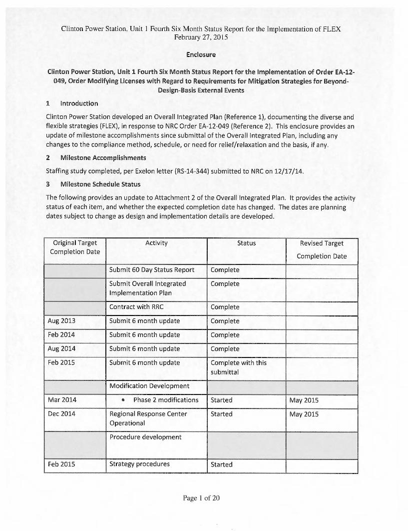
3 Milestone Schedule Status
The following provides an update to Attachment 2 of the Overall Integrated Plan. It provides the activity
status of each item, and whether the expected completion date has changed. The dates are planning
dates subject to change as design and implementation details are developed.
Original Target
Completion Date
Activity Status Revised Target
Completion Date
Submit 60 Day Status Report Complete
Submit Overall Integrated
Implementation Plan
Complete
Contract with RRC Complete
Aug 2013 Submit 6 month update Complete
Feb 2014 Submit 6 month update Complete
Aug 2014 Submit 6 month update Complete
Feb 2015 Submit 6 month update Complete with this
submittal
Modification Development
Mar 2014 • Phase 2 modifications Started May 2015
Dec 2014 Regional Response Center
Operational
Started May 2015
Procedure development
Feb 2015 Strategy procedures Started
Page 1 of 20
Clinton Power Station. Unit 1 Fourth Six Month Status Report for the Implementation of FLEX February 27, 2015
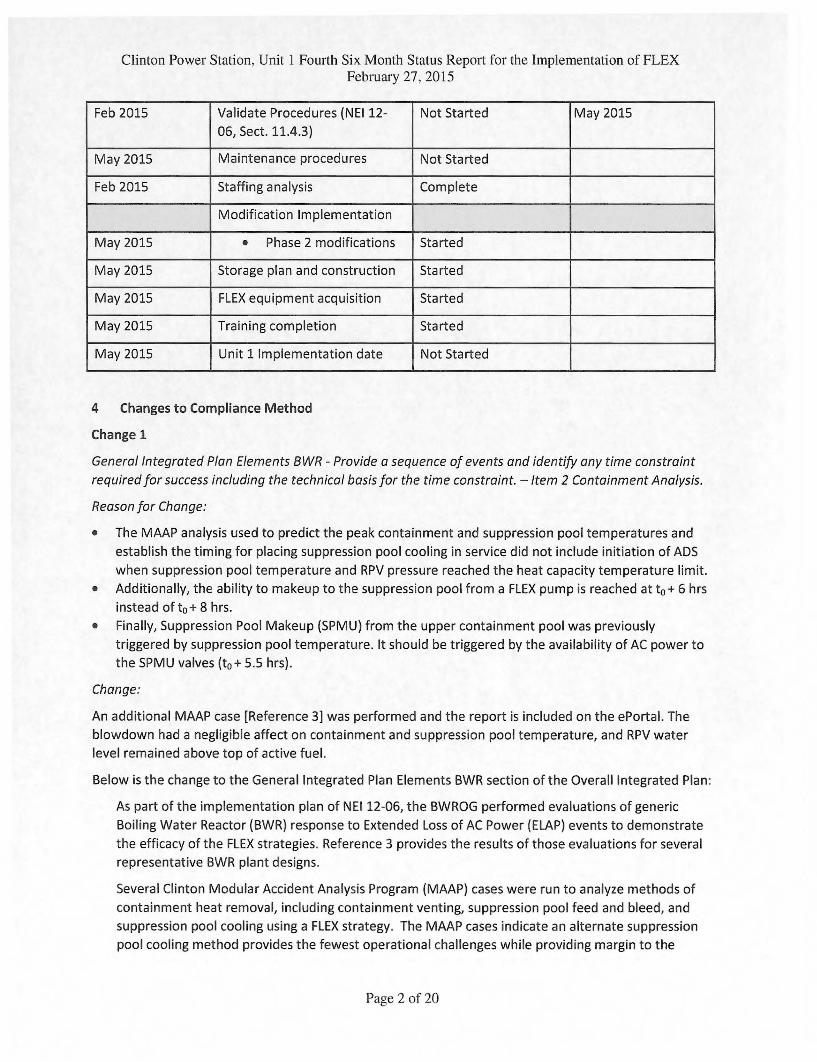
Feb 2015 Validate Procedures (NEI 12-
06, Sect. 11.4.3)
Not Started May 2015
May 2015 Maintenance procedures Not Started
Feb 2015 Staffing analysis Complete
Modification Implementation
May 2015 • Phase 2 modifications Started
May 2015 Storage plan and construction Started
May 2015 FLEX equipment acquisition Started
May 2015 Training completion Started
May 2015 Unit 1 Implementation date Not Started
4 Changes to Compliance Method
Change 1
General Integrated Plan Elements BWR - Provide a sequence of events and identify any time constraint
required for success including the technical basis for the time constraint. — Item 2 Containment Analysis.
Reason for Change:
• The MAAP analysis used to predict the peak containment and suppression pool temperatures and
establish the timing for placing suppression pool cooling in service did not include initiation of ADS
when suppression pool temperature and RPV pressure reached the heat capacity temperature limit.
• Additionally, the ability to makeup to the suppression pool from a FLEX pump is reached at to + 6 hrs
instead of to + 8 hrs.
• Finally, Suppression Pool Makeup (SPMU) from the upper containment pool was previously
triggered by suppression pool temperature. It should be triggered by the availability of AC power to
the SPMU valves (to + 5.5 hrs).
Change:
An additional MAAP case [Reference 3] was performed and the report is included on the ePortal. The
blowdown had a negligible affect on containment and suppression pool temperature, and RPV water
level remained above top of active fuel.
Below is the change to the General Integrated Plan Elements BWR section of the Overall Integrated Plan:
As part of the implementation plan of NEI 12-06, the BWROG performed evaluations of generic
Boiling Water Reactor (BWR) response to Extended Loss of AC Power (ELAP) events to demonstrate
the efficacy of the FLEX strategies. Reference 3 provides the results of those evaluations for several
representative BWR plant designs.
Several Clinton Modular Accident Analysis Program (MAAP) cases were run to analyze methods of
containment heat removal, including containment venting, suppression pool feed and bleed, and
suppression pool cooling using a FLEX strategy. The MAAP cases indicate an alternate suppression
pool cooling method provides the fewest operational challenges while providing margin to the
Page 2 of 20
Clinton Power Station, Unit 1 Fourth Six Month Status Report for the Implementation of FLEX February 27, 2015
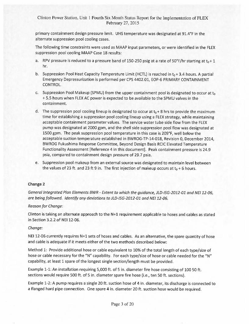
primary containment design pressure limit. UHS temperature was designated at 91.4°F in the
alternate suppression pool cooling cases.
The following time constraints were used as MAAP input parameters, or were identified in the FLEX
suppression pool cooling MAAP Case 18 results:
a. RPV pressure is reduced to a pressure band of 150-250 psig at a rate of 50°F/hr starting at to + 1 hr.
b. Suppression Pool Heat Capacity Temperature Limit (HCTL) is reached in to + 3.4 hours. A partial
Emergency Depressurization is performed per CPS 4402.01, EOP-6 PRIMARY CONTAINMENT
CONTROL.
c. Suppression Pool Makeup (SPMU) from the upper containment pool is designated to occur at to
+ 5.5 hours when FLEX AC power is expected to be available to the SPMU valves in the
containment.
d. The suppression pool cooling lineup is designated to occur at to + 8 hrs to provide the maximum
time for establishing a suppression pool cooling lineup using a FLEX strategy, while maintaining
acceptable containment parameter values. The service water tube side flow from the FLEX
pump was designated at 2000 gpm, and the shell side suppression pool flow was designated at
1500 gpm. The peak suppression pool temperature in this case is 209°F, well below the
acceptable suction temperature established in BWROG-TP-14-018, Revision 0, December 2014,
BWROG Fukushima Response Committee, Beyond Design Basis RCIC Elevated Temperature
Functionality Assessment [Reference 4 in this document]. Peak containment pressure is 24.9
psia, compared to containment design pressure of 29.7 psia.
e. Suppression pool makeup from an external source was designated to maintain level between
the values of 23 ft. and 23 ft 9 in. The first injection of makeup occurs at to + 6 hours.
Change 2
General Integrated Plan Elements BWR - Extent to which the guidance, JLD-ISG-2012-01 and NEI 12-06,
are being followed. Identify any deviations to JLD-!SG-2012-01 and NEI 12-06.
Reason for Change:
Clinton is taking an alternate approach to the N+1 requirement applicable to hoses and cables as stated
in Section 3.2.2 of NEI 12-06.
Change:
NEI 12-06 currently requires N+1 sets of hoses and cables. As an alternative, the spare quantity of hose
and cable is adequate if it meets either of the two methods described below:
Method 1: Provide additional hose or cable equivalent to 10% of the total length of each type/size of
hose or cable necessary for the "N" capability. For each type/size of hose or cable needed for the "N"
capability, at least 1 spare of the longest single section/length must be provided.
Example 1-1: An installation requiring 5,000 ft. of 5 in. diameter fire hose consisting of 100 50 ft.
sections would require 500 ft. of 5 in. diameter spare fire hose (i.e., ten 50 ft. sections).
Example 1-2: A pump requires a single 20 ft. suction hose of 4 in. diameter, its discharge is connected to
a flanged hard pipe connection. One spare 4 in. diameter 20 ft. suction hose would be required.
Page 3 of 20
Clinton Power Station. Unit 1 Fourth Six Month Status Report for the Implementation of FLEX February 27. 2015
Example 1-3: An electrical strategy requires 350 ft. cable runs of 4/0 cable to support 480 volt loads.
The cable runs are made up of 50 ft. sections coupled together. Eight cable runs (2 cables runs per
phase and 2 cable runs for the neutral) totaling 2800 ft. of cable (56 sections) are required. A minimum
of 280 ft. spare cable would be required or 6 spare 50 ft. sections.
Example 1-4: An electrical strategy requires 100 ft. of 4/0 cable (4 cables, 100 ft. each) to support one
set of 4 kv loads and 50 ft. of 4/0 (4 cables, 50 ft. each) to support another section of 4 kv loads. The
total length of 4/0 cable is 600 ft. (100 ft. x 4 plus 50 ft. x 4). One spare 100' 4/0 cable would be
required representing the longest single section/length.
Method 2: Provide spare cabling and hose of sufficient length and sizing to replace the single longest run
needed to support any single FLEX strategy.
Example 2-1 —A FLEX strategy for a two unit site requires 8 runs each of 500 ft. of 5 in. diameter hose
(4000 ft. per unit). The total length of 5 in. diameter hose required for the site is 8000 ft. with the
longest run of 500 ft. Using this method, 500 ft. of 5 in. diameter spare hose would be required.
For either alternative method, both the N sets of hoses or cables and the spare set of hoses or cables
would all be kept in a location that meets the reasonable protection requirements for the site.
Basis for an alternative approach:
Hoses and cables are passive devices unlikely to fail provided they are appropriately inspected and
maintained. The most likely cause of failure is mechanical damage during handling provided that the
hoses and cables are stored in areas with suitable environmental conditions (e.g., cables stored in a dry
condition and not subject to chemical or petroleum products). The hoses and cables for the FLEX
strategies will be stored and maintained in accordance with manufacturers' recommendations including
any shelf life requirements. Initial inspections and periodic inspections or testing will be incorporated in
the site's maintenance and testing program implemented in accordance with Section 11.5 of NEI 12-06.
Therefore, the probability of a failure occurring during storage is minimal, resulting in the only likely
failure occurring during implementation. Mechanical damage will likely occur in a single section versus
a complete set of hose or cable. Therefore, the N+1 alternative addresses the longest individual
section/length of hose or cable.
Providing either a spare cable or hose of a length of 10% of the total length necessary for the "N"
capability or alternatively providing spare cabling or hose of sufficient length and sizing to replace the
single longest run needed to support any single FLEX strategy is sufficient to ensure a strategy can be
implemented. Mechanical damage during implementation can be compensated for by having enough
spares to replace any damaged sections with margin. It is reasonable to expect that an entire set of
hoses or cables would not be damaged provided they have been reasonably protected.
Change 3
Attachment 1A - Sequence of Events Timeline
Reason for Change:
A calculation of Spent Fuel Pool area temperature following a BDBEE indicates the need to deploy hoses
and monitor nozzles for the Spent Fuel Pool Spray strategy during the first 11 hours of the loss of power.
Page 4 of 20
Clinton Power Station. Unit 1 Fourth Six Month Status Report for the Implementation of FLEX February 27, 2015
Change:
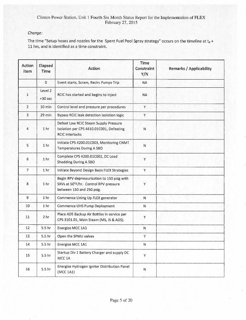
The time "Setup hoses and nozzles for the Spent Fuel Pool Spray strategy" occurs on the timeline at to +
11 hrs, and is identified as a time constraint.
Action
item
Elapsed
Time Action
Time
Constraint
Y/N
Remarks / Applicability
0 Event starts, Scram, Recirc Pumps Trip NA
1 Level 2
+30 sec RCIC has started and begins to inject NA
2 10 min Control level and pressure per procedures Y
3 29 min Bypass RCIC leak detection isolation logic Y
4 1 hr
Defeat Low RCIC Steam Supply Pressure
Isolation per CPS 4410.01C001, Defeating
RCIC Interlocks
N
5 1 hr Initiate CPS 4200.01C003, Monitoring CNMT
Temperatures During A SBO N
6 1 hr Complete CPS 4200.01C002, DC Load
Shedding During A SBO Y
7 1 hr Initiate Beyond Design Basis FLEX Strategies Y
8 1 hr
Begin RPV depressurization to 150 psig with
SRVs at 50°F/hr. Control RPV pressure
between 150 and 250 psig.
Y
9 1 hr Commence Lining Up FLEX generator N
10 1 hr Commence UHS Pump Deployment N
11 2 hr Place ADS Backup Air Bottles in service per
CPS 3101.01, Main Steam (MS, IS & ADS). Y
12 5.5 hr Energize MCC 1A3 N
13 5.5 hr Open the SPMU valves Y
14 5.5 hr Energize MCC 1A1 N
15 5.5 hr Startup Div 1 Battery Charger and supply DC
MCC 1A Y
16 5.5 hr Energize Hydrogen Igniter Distribution Panel
(MCC 1A1) N
Page 5 of 20
Clinton Power Station. Unit 1 Fourth Six Month Status Report for the Implementation of FLEX February 27. 2015
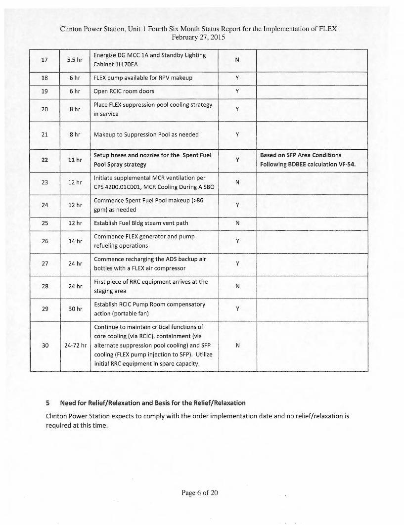
17 5.5 hr Energize DG MCC 1A and Standby Lighting
Cabinet 1LL70EA N
18 6 hr FLEX pump available for RPV makeup Y
19 6 hr Open RCIC room doors Y
20 8 hr Place FLEX suppression pool cooling strategy
in service Y
21 8 hr Makeup to Suppression Pool as needed Y
22 11 hr Setup hoses and nozzles for the Spent Fuel
Pool Spray strategy Y
Based on SFP Area Conditions
Following BDBEE calculation VF-54.
23 12 hr Initiate supplemental MCR ventilation per
CPS 4200.01C001, MCR Cooling During A SBO N
24 12 hr Commence Spent Fuel Pool makeup (>86
gpm) as needed Y
25 12 hr Establish Fuel Bldg steam vent path N
26 14 hr Commence FLEX generator and pump
refueling operations Y
27 24 hr Commence recharging the ADS backup air
bottles with a FLEX air compressor Y
28 24 hr First piece of RRC equipment arrives at the
staging area N
29 30 hr Establish RCIC Pump Room compensatory
action (portable fan) Y
30 24-72 hr
Continue to maintain critical functions of
core cooling (via RCIC), containment (via
alternate suppression pool cooling) and SFP
cooling (FLEX pump injection to SFP). Utilize
initial RRC equipment in spare capacity.
N
5 Need for Relief/Relaxation and Basis for the Relief/Relaxation
Clinton Power Station expects to comply with the order implementation date and no relief/relaxation is required at this time.
Page 6 of 20
Clinton Power Station. Unit 1 Fourth Six Month Status Report for the Implementation of FLEX
February 27,2015
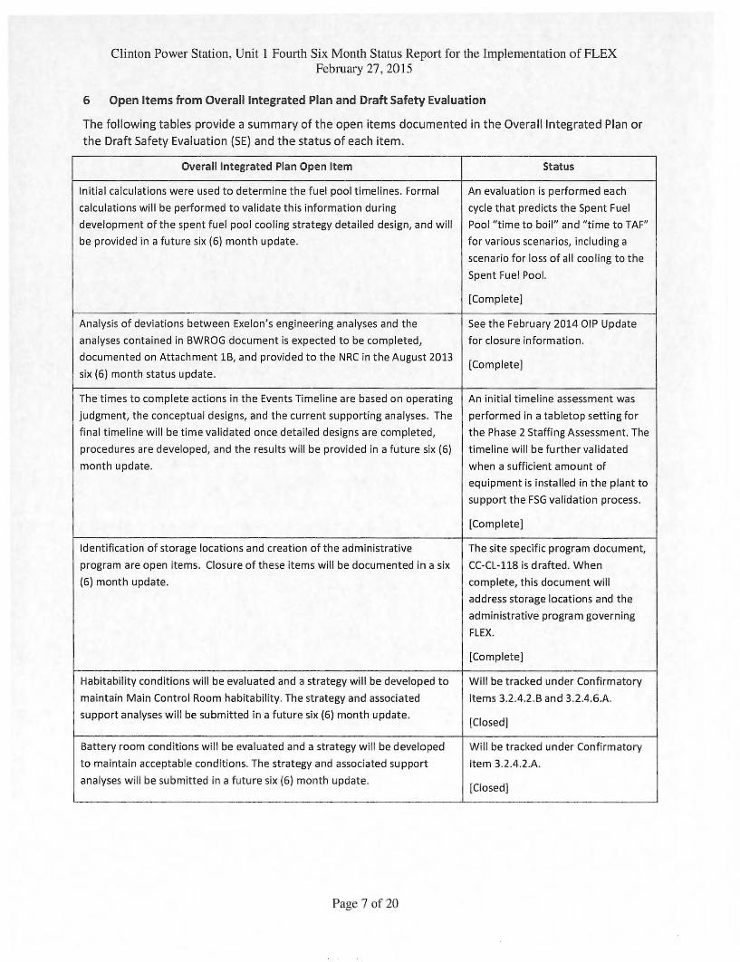
6 Open Items from Overall Integrated Plan and Draft Safety Evaluation
The following tables provide a summary of the open items documented in the Overall Integrated Plan or
the Draft Safety Evaluation (SE) and the status of each item.
Overall Integrated Plan Open Item Status
Initial calculations were used to determine the fuel pool timelines. Formal
calculations will be performed to validate this information during
development of the spent fuel pool cooling strategy detailed design, and will
be provided in a future six (6) month update.
An evaluation is performed each
cycle that predicts the Spent Fuel
Pool "time to boil" and "time to TAF"
for various scenarios, including a
scenario for loss of all cooling to the
Spent Fuel Pool.
[Complete]
Analysis of deviations between Exelon's engineering analyses and the
analyses contained in BWROG document is expected to be completed,
documented on Attachment 16, and provided to the NRC in the August 2013
six (6) month status update.
See the February 2014 DIP Update
for closure information.
[Complete]
The times to complete actions in the Events Timeline are based on operating
judgment, the conceptual designs, and the current supporting analyses. The
final timeline will be time validated once detailed designs are completed,
procedures are developed, and the results will be provided in a future six (6)
month update.
An initial timeline assessment was
performed in a tabletop setting for
the Phase 2 Staffing Assessment. The
timeline will be further validated
when a sufficient amount of
equipment is installed in the plant to
support the FSG validation process.
[Complete]
Identification of storage locations and creation of the administrative
program are open items. Closure of these items will be documented in a six
(6) month update.
The site specific program document,
CC-CL-118 is drafted. When
complete, this document will
address storage locations and the
administrative program governing
FLEX.
[Complete]
Habitability conditions will be evaluated and a strategy will be developed to
maintain Main Control Room habitability. The strategy and associated
support analyses will be submitted in a future six (6) month update.
Will be tracked under Confirmatory
Items 3.2.4.2.6 and 3.2.4.6.A.
[Closed]
Battery room conditions will be evaluated and a strategy will be developed
to maintain acceptable conditions. The strategy and associated support
analyses will be submitted in a future six (6) month update.
Will be tracked under Confirmatory
Item 3.2.4.2.A.
[Closed]
Page 7 of 20
Clinton Power Station, Unit l Fourth Six Month Status Report for the Implementation of FLEX February 27, 2015
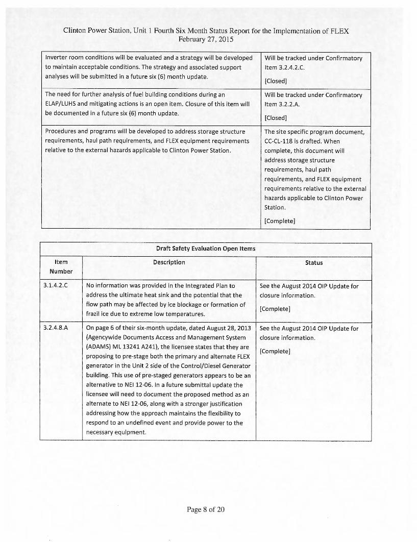
Inverter room conditions will be evaluated and a strategy will be developed
to maintain acceptable conditions. The strategy and associated support
analyses will be submitted in a future six (6) month update.
Will be tracked under Confirmatory
Item 3.2.4.2.C.
[Closed]
The need for further analysis of fuel building conditions during an Will be tracked under Confirmatory
ELAP/LUHS and mitigating actions is an open item. Closure of this item will
be documented in a future six (6) month update.
Item 3.2.2.A.
[Closed]
Procedures and programs will be developed to address storage structure
requirements, haul path requirements, and FLEX equipment requirements
The site specific program document,
CC-CL-118 is drafted. When
relative to the external hazards applicable to Clinton Power Station. complete, this document will
address storage structure
requirements, haul path
requirements, and FLEX equipment
requirements relative to the external
hazards applicable to Clinton Power
Station.
[Complete]
Draft Safety Evaluation Open Items
Item
Number
Description Status
3.1.4.2.0 No information was provided in the Integrated Plan to
address the ultimate heat sink and the potential that the
flow path may be affected by ice blockage or formation of
frazil ice due to extreme low temperatures.
See the August 2014 01P Update for
closure information.
[Complete]
3.2.4.8.A On page 6 of their six-month update, dated August 28, 2013
(Agencywide Documents Access and Management System
(ADAMS) ML 13241 A241), the licensee states that they are
proposing to pre-stage both the primary and alternate FLEX
generator in the Unit 2 side of the Control/Diesel Generator
building. This use of pre-staged generators appears to be an
alternative to NEI 12-06.1n a future submittal update the
licensee will need to document the proposed method as an
alternate to NEI 12-06, along with a stronger justification
addressing how the approach maintains the flexibility to
respond to an undefined event and provide power to the
necessary equipment.
See the August 2014 01P Update for
closure information.
[Complete]
Page 8 of 20
Clinton Power Station, Unit 1 Fourth Six Month Status Report for the Implementation of FLEX February 27, 2015
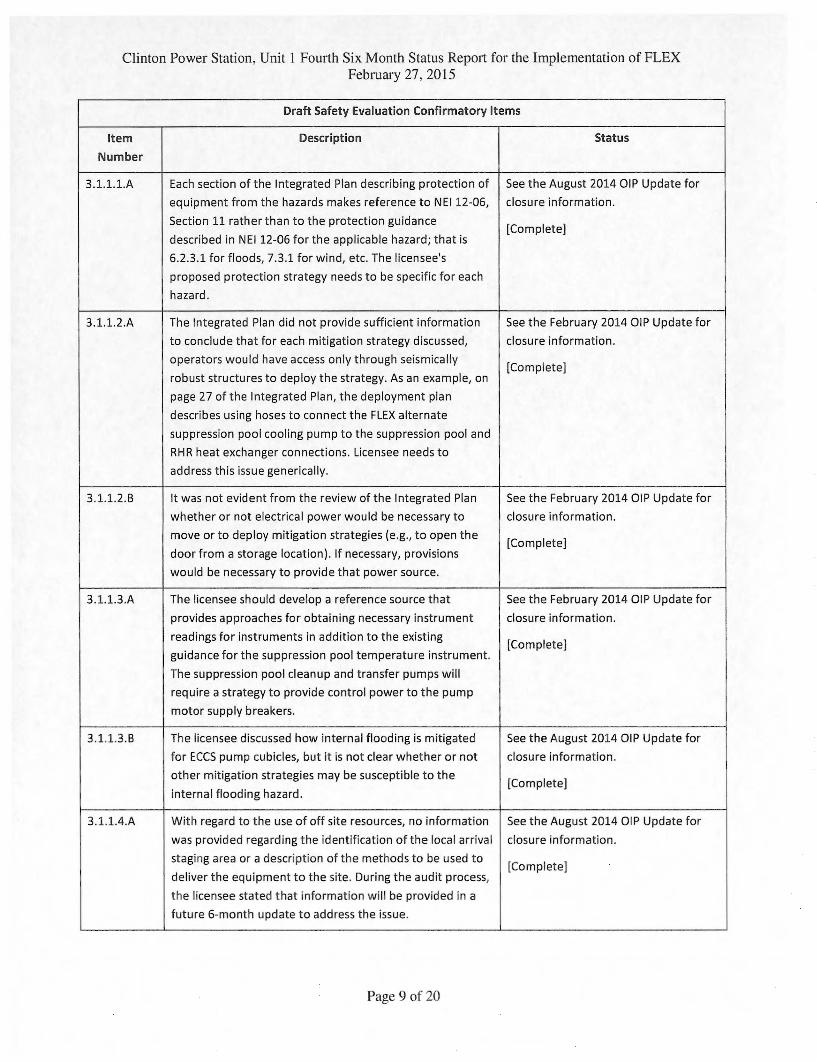
Draft Safety Evaluation Confirmatory Items
Item
Number
Description Status
3.1.1.1.A Each section of the Integrated Plan describing protection of
equipment from the hazards makes reference to NEI 12-06,
Section 11 rather than to the protection guidance
described in NEI 12-06 for the applicable hazard; that is
6.2.3.1 for floods, 7.3.1 for wind, etc. The licensee's
proposed protection strategy needs to be specific for each
hazard.
See the August 2014 DIP Update for
closure information.
[Complete]
3.1.1.2.A The Integrated Plan did not provide sufficient information
to conclude that for each mitigation strategy discussed,
operators would have access only through seismically
robust structures to deploy the strategy. As an example, on
page 27 of the Integrated Plan, the deployment plan
describes using hoses to connect the FLEX alternate
suppression pool cooling pump to the suppression pool and
RHR heat exchanger connections. Licensee needs to
address this issue generically.
See the February 2014 DIP Update for
closure information.
[Complete]
3.1.1.2.6 It was not evident from the review of the Integrated Plan
whether or not electrical power would be necessary to
move or to deploy mitigation strategies (e.g., to open the
door from a storage location). If necessary, provisions
would be necessary to provide that power source.
See the February 2014 DIP Update for
closure information.
[Complete]
3.1.1.3.A The licensee should develop a reference source that
provides approaches for obtaining necessary instrument
readings for instruments in addition to the existing
guidance for the suppression pool temperature instrument.
The suppression pool cleanup and transfer pumps will
require a strategy to provide control power to the pump
motor supply breakers.
See the February 2014 DIP Update for
closure information.
[Complete]
3.1.1.3.6 The licensee discussed how internal flooding is mitigated
for ECCS pump cubicles, but it is not clear whether or not
other mitigation strategies may be susceptible to the
internal flooding hazard.
See the August 2014 DIP Update for
closure information.
[Complete]
3.1.1.4.A With regard to the use of off site resources, no information
was provided regarding the identification of the local arrival
staging area or a description of the methods to be used to
deliver the equipment to the site. During the audit process,
the licensee stated that information will be provided in a
future 6-month update to address the issue.
See the August 2014 DIP Update for
closure information.
[Complete]
Page 9 of 20
Clinton Power Station, Unit 1 Fourth Six Month Status Report for the Implementation of FLEX February 27, 2015
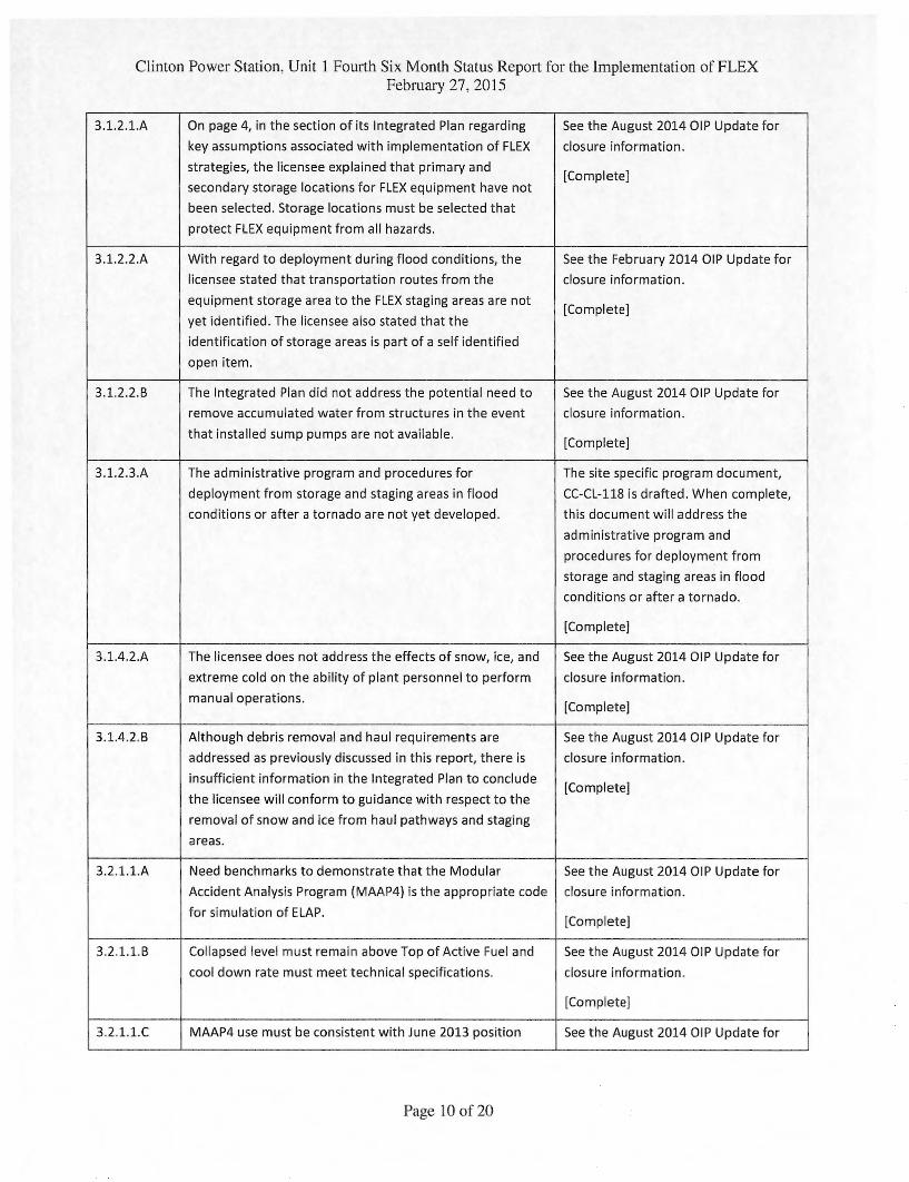
3.1.2.1.A On page 4, in the section of its Integrated Plan regarding
key assumptions associated with implementation of FLEX
strategies, the licensee explained that primary and
secondary storage locations for FLEX equipment have not
been selected. Storage locations must be selected that
protect FLEX equipment from all hazards.
See the August 2014 01P Update for
closure information.
[Complete]
3.1.2.2.A With regard to deployment during flood conditions, the
licensee stated that transportation routes from the
equipment storage area to the FLEX staging areas are not
yet identified. The licensee also stated that the
identification of storage areas is part of a self identified
open item.
See the February 2014 01P Update for
closure information.
[Complete]
3.1.2.2.B The Integrated Plan did not address the potential need to
remove accumulated water from structures in the event
that installed sump pumps are not available.
See the August 2014 01P Update for
closure information.
[Complete]
3.1.2.3.A The administrative program and procedures for
deployment from storage and staging areas in flood
conditions or after a tornado are not yet developed,
The site specific program document,
CC-CL-118 is drafted. When complete,
this document will address the
administrative program and
procedures for deployment from
storage and staging areas in flood
conditions or after a tornado.
[Complete]
3.1.4.2.A The licensee does not address the effects of snow, ice, and
extreme cold on the ability of plant personnel to perform
manual operations.
See the August 2014 01P Update for
closure information.
[Complete]
3.1.4.2.6 Although debris removal and haul requirements are
addressed as previously discussed in this report, there is
insufficient information in the Integrated Plan to conclude
the licensee will conform to guidance with respect to the
removal of snow and ice from haul pathways and staging
areas.
See the August 2014 01P Update for
closure information.
[Complete]
3.2.1.1.A Need benchmarks to demonstrate that the Modular
Accident Analysis Program (MAAP4) is the appropriate code
for simulation of ELAP.
See the August 2014 01P Update for
closure information.
[Complete]
3.2.1.1.6 Collapsed level must remain above Top of Active Fuel and
cool down rate must meet technical specifications.
See the August 2014 01P Update for
closure information.
[Complete]
3.2.1.1.0 MAAP4 use must be consistent with June 2013 position See the August 2014 01P Update for
Page 10 of 20
Clinton Power Station, Unit 1 Fourth Six Month Status Report for the Implementation of FLEX February 27. 2015
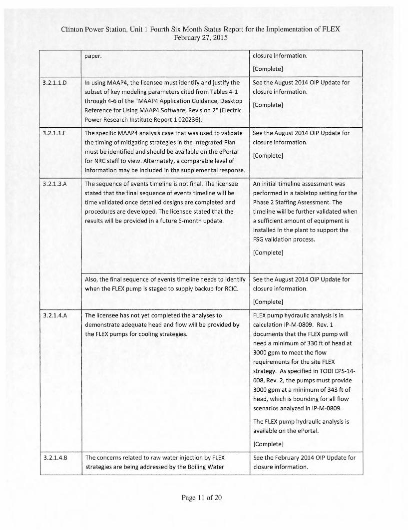
paper. closure information.
[Complete]
3.2.1.1.0 In using MAAP4, the licensee must identify and justify the
subset of key modeling parameters cited from Tables 4-1
through 4-6 of the "MAAP4 Application Guidance, Desktop
Reference for Using MAAP4 Software, Revision 2" (Electric
Power Research Institute Report 1 020236).
See the August 2014 01P Update for
closure information.
[Complete]
3.2.1.1.E The specific MAAP4 analysis case that was used to validate
the timing of mitigating strategies in the Integrated Plan
must be identified and should be available on the ePortal
for NRC staff to view. Alternately, a comparable level of
information may be included in the supplemental response.
See the August 2014 01P Update for
closure information.
[Complete]
3.2.1.3.A The sequence of events timeline is not final. The licensee
stated that the final sequence of events timeline will be
time validated once detailed designs are completed and
procedures are developed. The licensee stated that the
results will be provided in a future 6-month update.
An initial timeline assessment was
performed in a tabletop setting for the
Phase 2 Staffing Assessment. The
timeline will be further validated when
a sufficient amount of equipment is
installed in the plant to support the
FSG validation process.
[Complete]
Also, the final sequence of events timeline needs to identify
when the FLEX pump is staged to supply backup for RCIC.
See the August 2014 01P Update for
closure information.
[Complete]
3.2.1.4.A The licensee has not yet completed the analyses to
demonstrate adequate head and flow will be provided by
the FLEX pumps for cooling strategies.
FLEX pump hydraulic analysis is in
calculation IP-M-0809. Rev. 1
documents that the FLEX pump will
need a minimum of 330 ft of head at
3000 gpm to meet the flow
requirements for the site FLEX
strategy. As specified in TODI CPS-14-
008, Rev. 2, the pumps must provide
3000 gpm at a minimum of 343 ft of
head, which is bounding for all flow
scenarios analyzed in IP-M-0809.
The FLEX pump hydraulic analysis is
available on the ePortal.
[Complete]
3.2.1.4.B The concerns related to raw water injection by FLEX
strategies are being addressed by the Boiling Water
See the February 2014 OIP Update for
closure information.
Page 11 of 20
Clinton Power Station. Unit 1 Fourth Six Month Status Report for the Implementation of FLEX February 27, 2015
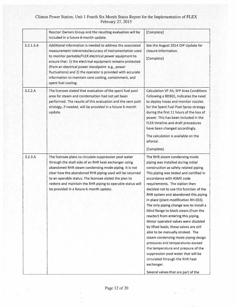
Reactor Owners Group and the resulting evaluation will be
included in a future 6-month update.
[Complete]
3.2.1.5.A Additional information is needed to address the associated
measurement tolerances/accuracy of instrumentation used
to monitor portable/FLEX electrical power equipment to
ensure that: 1) the electrical equipment remains protected
(from an electrical power standpoint- e.g., power
fluctuations) and 2) the operator is provided with accurate
information to maintain core cooling, containment, and
spent fuel cooling.
See the August 2014 01P Update for
closure information.
[Complete]
3.2.2.A The licensee stated that evaluation of the spent fuel pool
area for steam and condensation had not yet been
performed. The results of this evaluation and the vent path
strategy, if needed, will be provided in a future 6-month
update.
Calculation VF-54, SFP Area Conditions
Following a BDBEE, indicates the need
to deploy hoses and monitor nozzles
for the Spent Fuel Pool Spray strategy
during the first 11 hours of the loss of
power. This has been included in the
FLEX timeline and draft procedures
have been changed accordingly.
The calculation is available on the
ePortal.
[Complete]
3.2.3.A The licensee plans to circulate suppression pool water
through the shell side of an RHR heat exchanger using
abandoned RH R steam condensing mode piping. It is not
clear how the abandoned RHR piping used will be returned
to an operable status. The licensee stated the plan to
restore and maintain the RHR piping to operable status will
be provided in a future 6-month update.
The RHR steam condensing mode
piping was installed during initial
construction as safety related piping.
This piping was tested and certified in
accordance with ASME code
requirements. The station then
decided not to use this function of the
RHR system and abandoned this piping
in place (plant modification RH-033).
The only piping change was to install a
blind flange to block steam (from the
reactor) from entering this piping.
Motor operated valves were disabled
by lifted leads; these valves are still
able to be manually stroked. The
steam condensing mode piping design
pressures and temperatures exceed
the temperature and pressure of the
suppression pool water that will be
circulated through the RHR heat
exchanger.
Several valves that are part of the
Page 12 of 20
Clinton Power Station. Unit 1 Fourth Six Month Status Report for the Implementation of FLEX February 27. 2015
steam condensing mode piping will be
used for cooling the suppression pool
water. These valves will be manually
opened/closed to verify that they are
functional and can be used for the
FLEX strategies. Also, several of these
valves are part of Closed Loop Outside
Containment (CLOC) boundaries and
are periodically tested to verify leak
tightness.
[Complete]
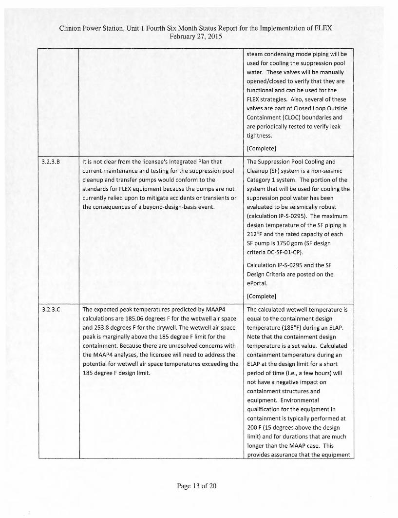
3.2.3.8 It is not clear from the licensee's Integrated Plan that
current maintenance and testing for the suppression pool
cleanup and transfer pumps would conform to the
standards for FLEX equipment because the pumps are not
currently relied upon to mitigate accidents or transients or
the consequences of a beyond-design-basis event,
The Suppression Pool Cooling and
Cleanup (SF) system is a non-seismic
Category 1 system. The portion of the
system that will be used for cooling the
suppression pool water has been
evaluated to be seismically robust
(calculation IP-S-0295). The maximum
design temperature of the SF piping is
212°F and the rated capacity of each
SF pump is 1750 gpm (SF design
criteria DC-SF-01-CP).
Calculation IP-S-0295 and the SF
Design Criteria are posted on the
ePortal.
[Complete]
3.2.3.0 The expected peak temperatures predicted by MAAP4
calculations are 185.06 degrees F for the wetwell air space
and 253.8 degrees F for the drywell. The wetwell air space
peak is marginally above the 185 degree F limit for the
containment. Because there are unresolved concerns with
the MAAP4 analyses, the licensee will need to address the
potential for wetwell air space temperatures exceeding the
185 degree F design limit,
The calculated wetwell temperature is
equal to the containment design
temperature (185°F) during an ELAP.
Note that the containment design
temperature is a set value. Calculated
containment temperature during an
ELAP at the design limit for a short
period of time (i.e., a few hours) will
not have a negative impact on
containment structures and
equipment. Environmental
qualification for the equipment in
containment is typically performed at
200 F (15 degrees above the design
limit) and for durations that are much
longer than the MAAP case. This
provides assurance that the equipment
Page 13 of 20
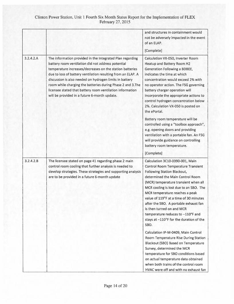
Clinton Power Station, Unit 1 Fourth Six Month Status Report for the Implementation of FLEX February 27, 2015
and structures in containment would
not be adversely impacted in the event
of an ELAP.
[Complete]
3.2.4.2.A The information provided in the Integrated Plan regarding
battery room ventilation did not address potential
temperature increases/decreases on the station batteries
due to loss of battery ventilation resulting from an ELAP. A
discussion is also needed on hydrogen limits in battery
room while charging the batteries during Phase 2 and 3.The
licensee stated that battery room ventilation information
will be provided in a future 6-month update.
Calculation VX-050, Inverter Room
Heatup and Battery Room H2
Generation Following a BDBEE,
indicates the time at which
concentration would exceed 2% with
no operator action. The FSG governing
battery charger operation will
incorporate the appropriate actions to
control hydrogen concentration below
2%. Calculation VX-050 is posted on
the ePortal.
Battery room temperature will be
controlled using a "toolbox approach",
e.g. opening doors and providing
ventilation with a portable fan. An FSG
will provide guidance on controlling
battery room temperature.
[Complete]
3.2.4.2.B The licensee stated on page 41 regarding phase 2 main
control room cooling that further analysis is needed to
develop strategies. These strategies and supporting analysis
are to be provided in a future 6-month update
Calculation 3C10-0390-001, Main
Control Room Temperature Transient
Following Station Blackout,
determined the Main Control Room
(MCR) temperature transient when all
MCR cooling is lost due to an SBO. The
MCR temperature reaches a peak
value of 119°F at a time of 30 minutes
after the SBO. A portable exhaust fan
is then turned on and MCR
temperature reduces to —110°F and
stays at —110°F for the duration of the
SBO.
Calculation IP-M-0409, Main Control
Room Temperature Rise During Station
Blackout (SBO) Based on Temperature
Survey, determined the MCR
temperature for SBO conditions based
on actual temperature data obtained
when both trains of the control room
HVAC were off and with no exhaust fan
Page 14 of 20
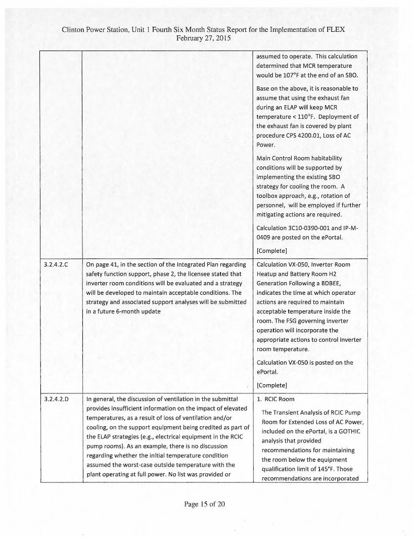
Clinton Power Station. Unit 1 Fourth Six Month Status Report for the Implementation of FLEX February 27. 2015
assumed to operate. This calculation
determined that MCR temperature
would be 107°F at the end of an SBO.
Base on the above, it is reasonable to
assume that using the exhaust fan
during an ELAP will keep MCR
temperature < 110°F. Deployment of
the exhaust fan is covered by plant
procedure CPS 4200.01, Loss of AC
Power.
Main Control Room habitability
conditions will be supported by
implementing the existing SBO
strategy for cooling the room. A
toolbox approach, e.g., rotation of
personnel, will be employed if further
mitigating actions are required.
Calculation 3C10-0390-001 and IP-M-
0409 are posted on the ePortal.
[Complete]
3.2.4.2.0 On page 41, in the section of the Integrated Plan regarding
safety function support, phase 2, the licensee stated that
inverter room conditions will be evaluated and a strategy
will be developed to maintain acceptable conditions. The
strategy and associated support analyses will be submitted
in a future 6-month update
Calculation VX-050, Inverter Room
Heatup and Battery Room H2
Generation Following a BDBEE,
indicates the time at which operator
actions are required to maintain
acceptable temperature inside the
room. The FSG governing inverter
operation will incorporate the
appropriate actions to control inverter
room temperature.
Calculation VX-050 is posted on the
ePortal.
[Complete]
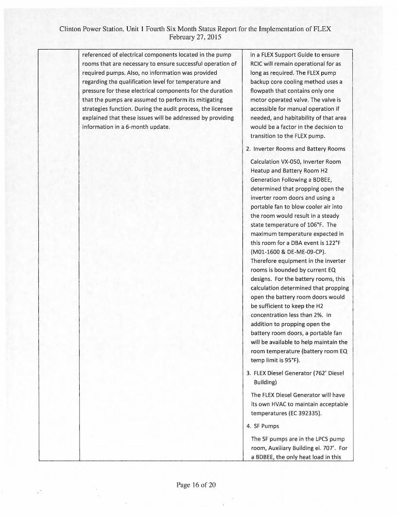
3.2.4.2.D In general, the discussion of ventilation in the submittal
provides insufficient information on the impact of elevated
temperatures, as a result of loss of ventilation and/or
cooling, on the support equipment being credited as part of
the ELAP strategies (e.g., electrical equipment in the RCIC
pump rooms). As an example, there is no discussion
regarding whether the initial temperature condition
assumed the worst-case outside temperature with the
plant operating at full power. No list was provided or
1. RCIC Room
The Transient Analysis of RCIC Pump
Room for Extended Loss of AC Power,
included on the ePortal, is a GOTHIC
analysis that provided
recommendations for maintaining
the room below the equipment
qualification limit of 145°F. Those
recommendations are incorporated
Page 15 of 20
Clinton Power Station. Unit 1 Fourth Six Month Status Report for the Implementation of FLEX February 27. 2015
referenced of electrical components located in the pump
in a FLEX Support Guide to ensure
rooms that are necessary to ensure successful operation of
RCIC will remain operational for as
required pumps. Also, no information was provided
long as required. The FLEX pump
regarding the qualification level for temperature and
backup core cooling method uses a
pressure for these electrical components for the duration
flowpath that contains only one
that the pumps are assumed to perform its mitigating
motor operated valve. The valve is
strategies function. During the audit process, the licensee accessible for manual operation if
explained that these issues will be addressed by providing
needed, and habitability of that area
information in a 6-month update. would be a factor in the decision to
transition to the FLEX pump.
2. Inverter Rooms and Battery Rooms
Calculation VX-050, Inverter Room
Heatup and Battery Room H2
Generation Following a BDBEE,
determined that propping open the
inverter room doors and using a
portable fan to blow cooler air into
the room would result in a steady
state temperature of 106°F. The
maximum temperature expected in
this room for a DBA event is 122°F
(M01-1600 & DE-ME-09-CP).
Therefore equipment in the inverter
rooms is bounded by current EQ
designs. For the battery rooms, this
calculation determined that propping
open the battery room doors would
be sufficient to keep the H2
concentration less than 2%. In
addition to propping open the
battery room doors, a portable fan
will be available to help maintain the
room temperature (battery room EQ
temp limit is 95°F).
3. FLEX Diesel Generator (762' Diesel
Building)
The FLEX Diesel Generator will have
its own HVAC to maintain acceptable
temperatures (EC 392335).
4. SF Pumps
The SF pumps are in the LPCS pump
room, Auxiliary Building el. 707'. For
a BDBEE, the only heat load in this
Page 16 of 20
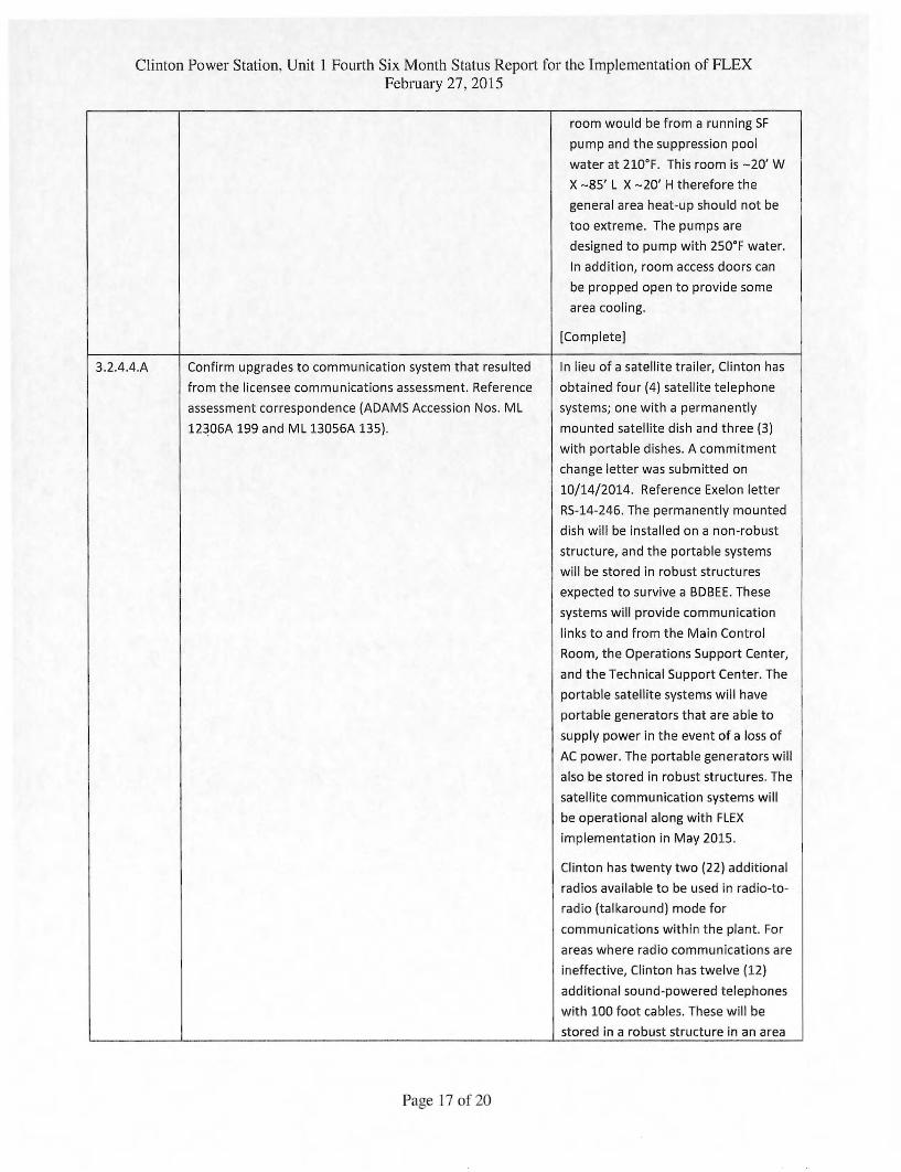
Clinton Power Station. Unit 1 Fourth Six Month Status Report for the Implementation of FLEX February 27. 2015
room would be from a running SF
pump and the suppression pool
water at 210°F. This room is —20' W
X —85' L X —20' H therefore the
general area heat-up should not be
too extreme. The pumps are
designed to pump with 250°F water.
In addition, room access doors can
be propped open to provide some
area cooling.
[Complete]
3.2.4.4.A Confirm upgrades to communication system that resulted
from the licensee communications assessment. Reference
assessment correspondence (ADAMS Accession Nos. ML
12306A 199 and ML 13056A 135).
In lieu of a satellite trailer, Clinton has
obtained four (4) satellite telephone
systems; one with a permanently
mounted satellite dish and three (3)
with portable dishes. A commitment
change letter was submitted on
10/14/2014. Reference Exelon letter
RS-14-246. The permanently mounted
dish will be installed on a non-robust
structure, and the portable systems
will be stored in robust structures
expected to survive a BDBEE. These
systems will provide communication
links to and from the Main Control
Room, the Operations Support Center,
and the Technical Support Center. The
portable satellite systems will have
portable generators that are able to
supply power in the event of a loss of
AC power. The portable generators will
also be stored in robust structures. The
satellite communication systems will
be operational along with FLEX
implementation in May 2015.
Clinton has twenty two (22) additional
radios available to be used in radio-to-
radio (talkaround) mode for
communications within the plant. For
areas where radio communications are
ineffective, Clinton has twelve (12)
additional sound-powered telephones
with 100 foot cables. These will be
stored in a robust structure in an area
Page 17 of 20
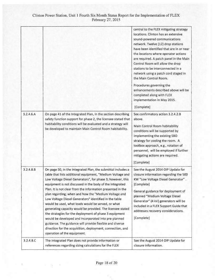
Clinton Power Station. Unit 1 Fourth Six Month Status Report for the Implementation of FLEX February 27. 2015
central to the FLEX mitigating strategy
locations. Clinton has an extensive
sound-powered communications
network. Twelve (12) drop stations
have been identified that are in or near
the locations where operator actions
are required. A patch panel in the Main
Control Room will allow the drop
stations to be interconnected in a
network using a patch cord staged in
the Main Control Room.
Procedures governing the
enhancements described above will be
completed along with FLEX
implementation in May 2015.
[Complete]
3.2.4.6.A On page 41 of the Integrated Plan, in the section describing
safety function support for phase 2, the licensee stated that
habitability conditions will be evaluated and a strategy will
be developed to maintain Main Control Room habitability.
See confirmatory action 3.2.4.2.6
above.
Main Control Room habitability
conditions will be supported by
implementing the existing 560
strategy for cooling the room. A
toolbox approach, e.g., rotation of
personnel, will be employed if further
mitigating actions are required.
[Complete]
3.2.4.8.13 On page 50, in the Integrated Plan, the submittal includes a
table that lists additional equipment, "Medium Voltage and
Low Voltage Diesel Generators", for phase 3; however, this
equipment is not discussed in the body of the Integrated
Plan. It is not clear from the information presented in the
plan regarding; when and how the "Medium Voltage and
Low Voltage Diesel Generators" identified in the table
would be used, what loads would be served, or what
generating capacity would be provided. The licensee stated
the strategies for the deployment of phase 3 equipment
would be developed and incorporated into pre-planned
guidance. The guidance will provide flexible and diverse
direction for the acquisition, deployment, connection, and
operation of the equipment.
See the August 2014 01P Update for
closure information regarding the 500
KW "Low Voltage Diesel Generator" .
[Complete]
General guidance for deployment of
planned "Medium Voltage Diesel
Generate (4 kV) generators will be
included in a FLEX Support Guide that
addresses recovery considerations.
[Complete]
3.2.4.8.0 The Integrated Plan does not provide information or
references regarding sizing calculations for the FLEX
See the August 2014 01P Update for
closure information.
Page 18 of 20
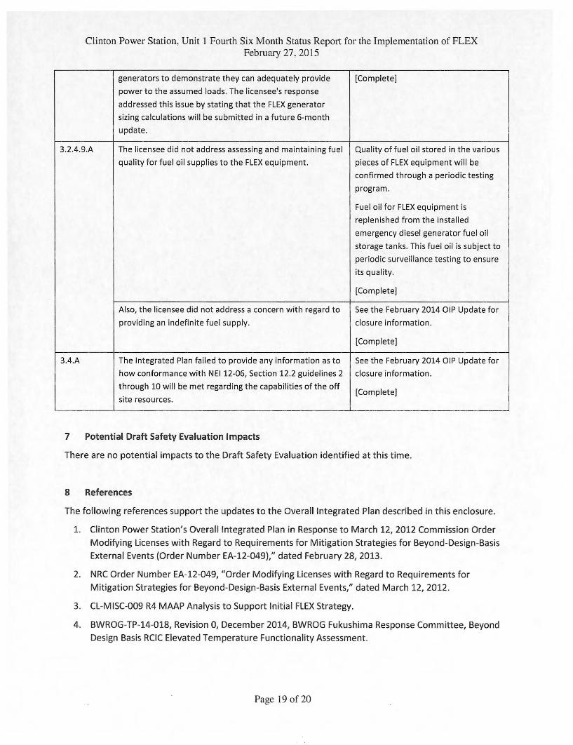
Clinton Power Station, Unit 1 Fourth Six Month Status Report for the Implementation of FLEX February 27. 2015
generators to demonstrate they can adequately provide
power to the assumed loads. The licensee's response
addressed this issue by stating that the FLEX generator
sizing calculations will be submitted in a future 6-month
update.
[Complete]
3.2.4.9.A The licensee did not address assessing and maintaining fuel
quality for fuel oil supplies to the FLEX equipment.
Quality of fuel oil stored in the various
pieces of FLEX equipment will be
confirmed through a periodic testing
program.
Fuel oil for FLEX equipment is
replenished from the installed
emergency diesel generator fuel oil
storage tanks. This fuel oil is subject to
periodic surveillance testing to ensure
its quality.
[Complete]
Also, the licensee did not address a concern with regard to
providing an indefinite fuel supply.
See the February 2014 01P Update for
closure information.
[Complete]
3.4.A The Integrated Plan failed to provide any information as to
how conformance with NEI 12-06, Section 12.2 guidelines 2
through 10 will be met regarding the capabilities of the off
site resources.
See the February 2014 01P Update for
closure information.
[Complete]
7 Potential Draft Safety Evaluation Impacts
There are no potential impacts to the Draft Safety Evaluation identified at this time.
8 References
The following references support the updates to the Overall Integrated Plan described in this enclosure.
1. Clinton Power Station's Overall Integrated Plan in Response to March 12, 2012 Commission Order
Modifying Licenses with Regard to Requirements for Mitigation Strategies for Beyond-Design-Basis
External Events (Order Number EA-12-049)," dated February 28, 2013.
2. NRC Order Number EA-12-049, "Order Modifying Licenses with Regard to Requirements for
Mitigation Strategies for Beyond-Design-Basis External Events," dated March 12, 2012.
3. CL-MISC-009 R4 MAAP Analysis to Support Initial FLEX Strategy.
4. BWROG-TP-14-018, Revision 0, December 2014, BWROG Fukushima Response Committee, Beyond
Design Basis RCIC Elevated Temperature Functionality Assessment.
Page 19 of 20
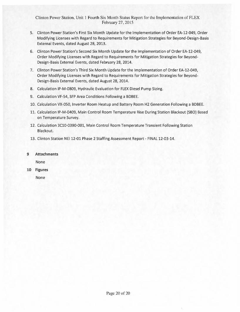
Clinton Power Station. Unit 1 Fourth Six Month Status Report for the Implementation of FLEX February 27, 2015
5. Clinton Power Station's First Six Month Update for the Implementation of Order EA-12-049, Order
Modifying Licenses with Regard to Requirements for Mitigation Strategies for Beyond-Design-Basis
External Events, dated August 28, 2013.
6. Clinton Power Station's Second Six Month Update for the Implementation of Order EA-12-049,
Order Modifying Licenses with Regard to Requirements for Mitigation Strategies for Beyond-
Design-Basis External Events, dated February 28, 2014.
7. Clinton Power Station's Third Six Month Update for the Implementation of Order EA-12-049,
Order Modifying Licenses with Regard to Requirements for Mitigation Strategies for Beyond-
Design-Basis External Events, dated August 28, 2014.
8. Calculation IP-M-0809, Hydraulic Evaluation for FLEX Diesel Pump Sizing.
9. Calculation VF-54, SFP Area Conditions Following a BDBEE.
10. Calculation VX-050, Inverter Room Heatup and Battery Room H2 Generation Following a BDBEE.
11. Calculation IP-M-0409, Main Control Room Temperature Rise During Station Blackout (SBO) Based
on Temperature Survey.
12. Calculation 3C10-0390-001, Main Control Room Temperature Transient Following Station
Blackout.
13. Clinton Station NEI 12-01 Phase 2 Staffing Assessment Report - FINAL 12-03-14.
9 Attachments
None
10 Figures
None
Page 20 of 20