Embed Size (px)
Citation preview
Michael P. Gallagher Vice President. License Renewal
Exelon Generation® Exelon Nuclear
200 Exelon Way
RS-15-165
June 25, 2015
Kennett Square, PA 19348
610 765 5958 Office 610 765 5956 Fax www.exeloncorp.com
10 CFR 50 10 CFR 51 10 CFR 54
U.S. Nuclear Regulatory Commission Attention: Document Control Desk Washington, DC 20555-0001
Subject:
References:
LaSalle County Station, Units 1 and 2 Facility Operating License Nos. NPF-11 and NPF-18 NRC Docket Nos. 50-373 and 50-374
Response to NRC Requests for Additional Information, Set 2, dated May 29, 2015 related to the LaSalle County Station, Units 1 and 2, License Renewal Application (TAC Nos. MF5347 AND MF5346)
1. Letter from Michael P. Gallagher, Exelon Generation Company LLC (Exelon), to NRC Document Control Desk, dated December 9, 2014, "Application for Renewed Operating Licenses"
2. Letter from Jeffrey S. Mitchell, US NRC to Michael P. Gallagher, Exelon, dated May 29, 2015, "Requests for Additional Information for the Review of the LaSalle County Station, Units 1 and 2 License Renewal Application - Set 2 (TAC Nos. MF5347 and MF5346)"
In Reference 1, Exelon Generation Company, LLC (Exelon) submitted the License Renewal Application (LRA) for the LaSalle County Station (LSCS), Units 1 and 2. In Reference 2, the NRC requested additional information to support staff review of the LRA.
Enclosure A contains the responses to this request for additional information.
Enclosure B contains updates to sections of the LRA affected by the responses.
There are no new or revised regulatory commitments contained in this letter.
If you have any questions, please contact Mrs. Shannon Rafferty-Czincila, Manager, LaSalle License Renewal Project, at 610-765-5526.
I declare under penalty of perjury that the foregoing is true and correct.
June 25, 2015 U.S. Nuclear Regulatory Commission Page 2
Executed on P b .,. 2.).,. '],o/ $'
Respectfully,
~(/At:-Vice President - License Renewal Projects Exelon Generation Company, LLC
Enclosures: A: Responses to Set 2 Requests for Additional Information B: Updates to Affected LRA Sections
cc: Regional Administrator- NRC Region Ill NRC Project Manager (Safety Review), NRR-DLR NRC Project Manager (Environmental Review), NRR-DLR NRC Project Manager, NRR-DORL- LaSalle County Station NRC Senior Resident Inspector, LaSalle County Station Illinois Emergency Management Agency - Division of Nuclear Safety
RS-15-165 Enclosure A Page 1 of 26
Enclosure A
Responses to Requests for Additional Information related to various sections of the LaSalle County Station (LSCS) License Renewal Application (LRA)
RAI B.2.1.7-1 RAI B.2.1.7-2 RAI B.2.1.7-3 RAI B.2.2.1-1 RAI B.2.2.1-2 RAI B.2.2.1-3 RAI B.2.1.20-1 RAI B.2.1.20-2 RAI B.2.1.20-3 RAI B.2.1.20-4 RAI B.2.1.28-1 RAI 3.3.2.1.11-1
RS-15-165 Enclosure A Page 2 of 26
RAI B.2.1.7-1:
Background:
Generic Aging Lessons Learned (GALL) Report aging management program (AMP) XI.M7, “BWR Stress Corrosion Cracking,” states that the program to manage intergranular stress corrosion cracking (IGSCC) in Boiling Water Reactor (BWR) coolant pressure boundary piping is delineated in NUREG-0313, Revision 2 “Technical Report on Material Selection and Process Guidelines for BWR Coolant Pressure Boundary Piping,” and Supplement 1 to NRC Generic Letter (GL) 88-01. The “detection of aging effects” program element of GALL Report AMP XI.M7 also states that modifications of the extent and schedule of inspection in NRC GL 88-01 are allowed in accordance with the inspection guidance in staff-approved Boiling Water Reactor Vessel and Internals Project (BWRVIP)-75-A. License Renewal Application (LRA) Section B.2.1.7 states that the BWR Stress Corrosion Cracking AMP is consistent with GALL Report AMP XI.M7. The LRA also states that hydrogen water chemistry and noble metals chemical addition have been implemented to further reduce susceptibility of piping systems exposed to reactor coolant to stress corrosion cracking. The LRA further indicates that welds classified as Category A (resistant materials) are subsumed into the Risk-Informed Inservice Inspection (RI-ISI) program in accordance with staff-approved EPRI Topical Report TR-112657, Revision B-A, Final Report, “Revised Risk- Informed Inservice Inspection Evaluation Procedure,” dated December 1999. During the audit, the staff noted that LaSalle County Station (LSCS), Units 1 and 2 implemented RI-ISI for the current (third) inservice inspection interval through the relief request process as approved in the NRC letter dated April 29, 2008 (Agencywide Documents Access and Management System (ADAMS) Accession No. ML080940215).
Issue:
The staff noted that the inspection extent for Category A welds, which are subsumed in the RI-ISI, may not be consistent with the guidance provided in GL 88-01 and BWRVIP-75-A since the RI-ISI adopts a risk-based selection process. Therefore, additional information is necessary to confirm whether the program is adequate to manage cracking due to IGSCC for Category A welds.
Request:
1. Clarify whether the applicant’s inspection extent for Category A welds, subsumed in the RI-ISI, is consistent with the guidance in GL 88-01 and BWRVIP-75-A.
2. If the inspection extent for Category A welds is different from the guidance in GL 88-01 and BWRVIP-75-A, provide the following information:
a. Clarification as to why the inspection extent for Category A welds is not identified as a program exception.
b. Justification for why the program is adequate to manage the aging effect of IGSCC for Category A welds, and an assessment of plant-specific operating experience to support the justification

RS-15-165 Enclosure A Page 3 of 26 Exelon Response:
1. The inspection extent for IGSCC Category A welds is consistent with the guidance in GL 88-01 and BWRVIP-75-A unless relief request is granted for future ISI intervals during the period of extended operation to allow Category A welds to continue to be subsumed under the Risk Informed ISI (RI-ISI) program. The relief request would be supported by appropriate technical justification and approved by the NRC.
The LSCS ISI Program Plan for the current 10-year interval applies normal water chemistry (NWC) conditions, therefore BWRVIP-75-A and GL 88-01 would require 25 percent of the IGSCC Category A welds to be inspected during the interval. BWRVIP-75-A, Section 3.1.2 also states that the Category A weld sampling can be reduced to 10 percent of the population without negative impact on safety provided risk-informed weld selections are employed.
As stated in LRA Section B.2.1.7, “Welds classified as Category A are subsumed into the Risk-Informed Inservice Inspection (RI-ISI) program in accordance with staff-approved EPRI Topical Report TR-112657, Revision B-A, Final Report, “Revised Risk-Informed Inservice Inspection Evaluation Procedure,” December 1999.” A RI-ISI methodology is currently implemented at LSCS that is consistent with TR-112657 Revision B-A and Code Case N-578-1, as described in Relief Request I3R-01 for the 3rd ISI interval that is effective from October 1, 2007 through September 30, 2017. This is the first full ISI 10-year interval that implements RI-ISI at LSCS. If during the period of extended operation, such relief is not approved allowing implementation of RI-ISI per TR-112657 Revision B-A, then IGSCC Category A welds will be inspected per the number of welds and frequency specified by BWRVIP-75-A, Table 3-1.
Within the RI-ISI program implemented in accordance with TR-112657 Revision B-A guidance there is no specific percentage of IGSCC Category A welds that are to be inspected in each 10-year ISI interval. All of the IGSCC Category A welds at LSCS are assigned Medium Risk Category 4 except for two Unit 2 welds that are assigned High Risk Category 2. The RI-ISI program requires 25 percent of the High Risk Category 2 welds and 10 percent of the Medium Risk Category 4 welds to be inspected during each 10-year ISI interval per the guidance within TR-112657, Revision B-A. However, since there are many other welds within the populations of High Risk Category 2 and Medium Risk Category 4 welds, the percentage of IGSCC Category A welds selected for inspection during each 10-year ISI interval may be more than, less than, or equal to 25 percent and 10 percent respectively. For example, during the 10-year period of 2003 through 2012, there were five IGSCC Category A welds (12 percent) inspected on Unit 1, and five IGSCC Category A welds (nine percent) inspected on Unit 2. If relief is approved by the NRC during the period of extended operation, allowing IGSCC Category A welds to continue to be subsumed under the RI-ISI program, then 25 percent of the High Risk Category 2 welds and 10 percent of the Medium Risk Category 4 welds will continue to be inspected during each interval.
Therefore, during the period of extended operation, if relief request is approved to continue to subsume IGSCC Category A welds under the RI-ISI program, then the percentage of IGSCC Category A welds inspected may not be as specified by BWRVIP-75-A and GL 88-01.
RS-15-165 Enclosure A Page 4 of 26
2. If relief request is approved by the NRC allowing IGSCC Category A welds to be subsumed under the RI-ISI program for future ISI intervals during the period of extended operation, then the inspection extent may be different from the guidance in GL 88-01 and BWRVIP-75-A, as discussed in the response to Request 1. a. The inspection extent for IGSCC Category A welds is not identified as a
program exception because without NRC approval of an ISI program relief request the inspection extent for Category A welds will be in accordance with BWRVIP-75-A, which is consistent with GALL Report AMP XI.M7.
Also, EPRI TR-112657, Revision B-A provides a staff-approved method for meeting NRC GL 88-01 commitments for establishing the frequency and extent of inspection for Category A welds. The NRC SER for EPRI TR-112657, Revision B-A, Section 3.1, Proposed Changes to ISI Programs, states, “The EPRI RI-ISI program would supersede augmented inspection programs for Category A welds for IGSCC for BWRs...” Section 3.3.1, Selection of Examination Locations, states, “For those IGSCC Category B through G welds that are in Risk Category 1, 2, 3, 5, 6, or 7, the number, location, and frequency of inspections are to be the same as in the existing plant IGSCC inspection program. Only IGSCC Category A welds are subsumed under the EPRI RI-ISI program.” Therefore, having the IGSCC Category A welds subsumed into the LSCS RI-ISI program in accordance with EPRI TR-112657, Revision B-A results in an inspection selection methodology that is in accordance with previously approved NRC guidance for meeting licensee commitments to NRC GL 88-01.
b. IGSCC Category A welds are defined within GL-88-01 as material that is
resistant to IGSCC; therefore, these welds are less likely to experience IGSCC than other welds (IGSCC Categories B through G) within the scope of the program. The NRC SER for EPRI TR-112657, Revision B-A, Introduction, states, “RI-ISI programs enhance overall safety (1) by focusing inspections of piping at highly risk significant locations and at locations where failure mechanisms are likely to be present and (2) by improving the effectiveness of inspection of components because the examination methods are based on the postulated failure mode and configuration of the piping structural element.”
There has never been a leak or an indication identified from an inspection that was indicative of IGSCC for any welds within the scope of the BWR Stress Corrosion Cracking program identified at LSCS Units 1 and 2. This indicates that the Water Chemistry program, selection of materials, and implementation of processes and programs that provide resistance to IGSCC have been effectively implemented at LSCS. Therefore, continuing to subsume the IGSCC Category A welds into the RI-ISI program in accordance with EPRI TR-112657, Revision B-A results in an adequate methodology to manage the aging effect of IGSCC for Category A welds.
RS-15-165 Enclosure A Page 5 of 26 RAI B.2.1.7-2:
Background:
LRA Section B.2.1.7 states that the LSCS BWR Stress Corrosion Cracking AMP is consistent with GALL Report AMP XI.M7, “BWR Stress Corrosion Cracking.” GALL Report AMP XI.M7, “BWR Stress Corrosion Cracking,” states that the program to manage IGSCC in BWR coolant pressure boundary piping is delineated in NUREG-0313, Revision 2 and Supplement 1 of NRC GL 88-01. The “detection of aging effects” program element of GALL Report AMP XI.M7 also states that modifications of the extent and schedule of inspection in NRC GL 88-01 are allowed in accordance with the inspection guidance in staff-approved BWRVIP-75-A. GL 88-01 Categories B and C welds are made of non-resistant materials to IGSCC. A stress improvement process was applied on Category B welds and Category C welds within the first 2 years of operation and after the first 2 years of operation, respectively. During the audit, the staff noted that the following onsite document describes inspection schedules and selections for Categories B and C welds during the third 10-year inspection interval.
• LaSalle County Nuclear Power Station Units 1 & 2 ISI Selection Document Third Ten-Year Inspection Interval, Revision 1, March 31, 2011.
Issue:
The staff also noted that the referenced onsite document indicates that inspection selections for Unit 2 Category B and C welds are as follows:
• For Unit 2 Category B welds, the number of welds to be inspected in accordance with BWRVIP-75-A (i.e., 25 percent every 10 years) is 33.5; however, the number of welds selected for inspection is only 25.
• For Unit 2 Category C welds, the number of welds to be inspected in accordance with BWRVIP-75-A (i.e., 25 percent every 10 years) is two; however, the number of welds selected for inspection is only one.
The inspection plan for the third 10-year interval indicates that in each of Categories B and C the number of welds selected for inspection at Unit 2 is less than that to be inspected in accordance with BWRVIP-75-A. Therefore, additional information is necessary to confirm the consistency of the program with GALL Report AMP XI.M7.
Request:
1. Provide justification as to why the inspection plan indicates that the number of Category B welds selected for inspection at LaSalle County Station, Unit 2 is less than that to be inspected in accordance with BWRVIP-75-A. In addition, justify why the number of Category C welds selected for inspection at Unit 2 is less than that to be inspected in accordance with BWRVIP-75-A. If the numbers chosen for inspection cannot be justified, adjust the inspection extents for Categories B and C welds in accordance with BWRVIP-75-A.
RS-15-165 Enclosure A Page 6 of 26
2. Discuss whether the applicant’s inspections indicated occurrence of IGSCC in Category B or Category C welds at LSCS in order to support the adequacy of the inspection frequency and scope.
Exelon Response:
1. The BWR Stress Corrosion Cracking program is in accordance with the guidance for inspection frequency and scope within BWRVIP-75-A for IGSCC Category B and C Welds as shown in Table 3-1 for normal water chemistry (NWC) conditions. Twenty-five percent of the Category B and C welds are being inspected during each 10-year period, and this frequency and scope of inspections will continue through the period of extended operation.
The reports within the referenced ISI Selection Document are based on the third 10-year ISI interval (October 1, 2007 through September 30, 2017); not the 10-year period used in tracking compliance with BWRVIP-75-A for IGSCC Category B through G welds. Therefore, the table in the referenced ISI Selection Document that indicates only 25 IGSCC Category B welds and one IGSCC Category C weld are selected is not used for selecting and scheduling inspection of IGSCC Category B through G welds. The reason that the current 10-year inspection period for BWRVIP-75-A doesn’t correspond with the 10-year ISI interval is that BWRVIP-75-A was implemented at LSCS on January 1, 2003. Therefore, the first 10-year period for tracking compliance with the inspection schedules in BWRVIP-75-A was from January 1, 2003 until December 31, 2012; the current 10-year period is January 1, 2013 through December 31, 2022; and subsequent 10-year periods will be on this bases. During the first 10-year period (2003-2012), 34 Category B welds and two Category C welds were inspected, which is in accordance with BWRVIP-75-A.
The status and schedule for inspection of Unit 2 Category B and C welds during the current 10-year period is as follows:
For Unit 2, there are 134 IGSCC Category B welds, eight IGSCC Category C welds, and two Category D welds. This results in 34 Category B welds and two Category C welds requiring inspection in every 10-year period in accordance with BWRVIP-75-A. For Category B welds, nine welds were inspected during L2R14 in 2013, and five were inspected during L2R15, in 2015. At least 20 additional welds are required to be inspected prior to the end of L2R18 in February of 2021, to meet the 25 percent requirement by December 31, 2022. For Category C welds, no Category C welds have been inspected to this point in the current 10-year period. Inspection of two welds is required prior to the end of L2R18 in February of 2021, to meet the 25 percent requirement by December 31, 2022.
2. The inspection frequency and scope for IGSCC Category B and C welds is in accordance with staff-approved BWRVIP-75-A, Table 3-1 for NWC. There have been no issues of IGSCC cracking of welds within the scope of the BWR Stress Corrosion Cracking program at LSCS Units 1 and 2 during their operating history; therefore, the adequacy of this inspection frequency and scope is supported.
RS-15-165 Enclosure A Page 7 of 26 RAI B.2.1.7-3:
Background:
LRA Section B.2.1.7 states that the BWR Stress Corrosion Cracking AMP is consistent with GALL Report AMP XI.M7, “BWR Stress Corrosion Cracking.” The “detection of aging effects” program element of GALL Report AMP XI.M7 indicates that the inspection extent and schedule are described in NRC GL 88-01 and modifications of the inspection extent and schedule are allowed in accordance with the staff-approved BWRVIP-75-A. GL 88-01 indicates that examinations performed under the scope of GL 88-01 should comply with the applicable Edition and Addenda of the ASME Code, Section XI, as specified in paragraph (g), “Inservice Inspection Requirements” of Title 10 of the Code of Federal Regulations (10 CFR) Part 50.55a, “Codes and Standards,” or as otherwise approved by the NRC. In addition, Information Notice No. 98-42, “Implementation of 10 CFR 50.55a(g) Inservice Inspection Requirements,” indicates that "essentially 100 percent" of the required examination volume for inservice inspections is defined as more than 90 percent of the specified examination volume. Issue: The staff noted that the following inservice inspection summary report for LSCS, Unit 2 indicates that the examination coverage of the BWRVIP-75-A inspections on Category B welds was as low as 50 percent.
• Table B of Post-Outage 90-Day Inservice Inspection (ISI) Summary Report, dated May 31, 2013 (ADAMS Accession No. ML13151A451)
The staff needs additional information to determine whether the limited examination coverage of the inspections is adequate to manage cracking due to IGSCC for the welds within the scope of the program.
Request:
1. Provide the average examination coverage of each weld category (i.e., each of Categories A through G) for each unit in order to characterize the overall degree of limited examination coverage. In addition, explain why the examination coverage is limited.
2. Justify why the program is adequate to manage cracking due to IGSCC without additional inspections that will compensate for the limited examination coverage of each weld category during an inspection period (e.g., every 10 years for Category B welds).
RS-15-165 Enclosure A Page 8 of 26 Exelon Response:
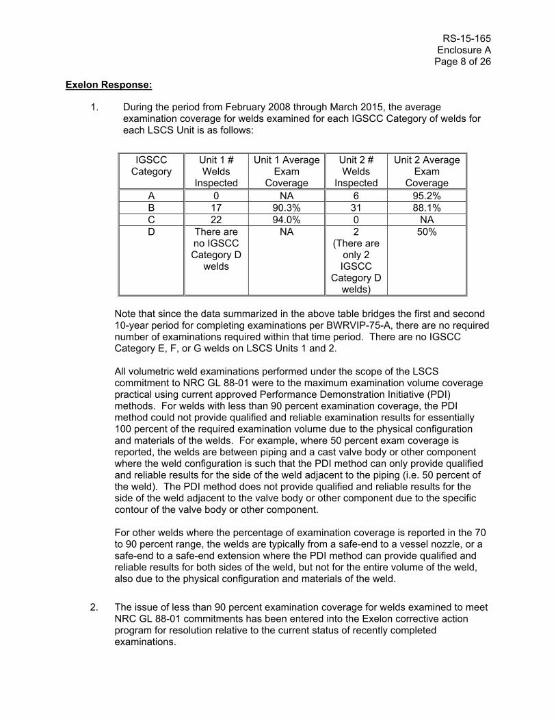
1. During the period from February 2008 through March 2015, the average examination coverage for welds examined for each IGSCC Category of welds for each LSCS Unit is as follows:
IGSCC
Category Unit 1 # Welds
Inspected
Unit 1 Average Exam
Coverage
Unit 2 # Welds
Inspected
Unit 2 Average Exam
Coverage A 0 NA 6 95.2% B 17 90.3% 31 88.1% C 22 94.0% 0 NA D There are
no IGSCC Category D
welds
NA 2 (There are
only 2 IGSCC
Category D welds)
50%
Note that since the data summarized in the above table bridges the first and second 10-year period for completing examinations per BWRVIP-75-A, there are no required number of examinations required within that time period. There are no IGSCC Category E, F, or G welds on LSCS Units 1 and 2. All volumetric weld examinations performed under the scope of the LSCS commitment to NRC GL 88-01 were to the maximum examination volume coverage practical using current approved Performance Demonstration Initiative (PDI) methods. For welds with less than 90 percent examination coverage, the PDI method could not provide qualified and reliable examination results for essentially 100 percent of the required examination volume due to the physical configuration and materials of the welds. For example, where 50 percent exam coverage is reported, the welds are between piping and a cast valve body or other component where the weld configuration is such that the PDI method can only provide qualified and reliable results for the side of the weld adjacent to the piping (i.e. 50 percent of the weld). The PDI method does not provide qualified and reliable results for the side of the weld adjacent to the valve body or other component due to the specific contour of the valve body or other component. For other welds where the percentage of examination coverage is reported in the 70 to 90 percent range, the welds are typically from a safe-end to a vessel nozzle, or a safe-end to a safe-end extension where the PDI method can provide qualified and reliable results for both sides of the weld, but not for the entire volume of the weld, also due to the physical configuration and materials of the weld.
2. The issue of less than 90 percent examination coverage for welds examined to meet NRC GL 88-01 commitments has been entered into the Exelon corrective action program for resolution relative to the current status of recently completed examinations.

RS-15-165 Enclosure A Page 9 of 26
Staff-approved Code Case N-460 allows for acceptable examination coverage of 90 percent for Class 1 and 2 welds. For IGSCC Category A welds that are subsumed into the Risk Informed Inservice (RI-ISI) Program in accordance with staff-approved EPRI TR-112657, Revision B-A, any examinations with coverage less than 90 percent will be addressed by a relief request submitted for NRC review and approval per 10 CFR 50.55a at the end of the ISI interval. For IGSCC Category D welds, there are only two welds in the population, both on Unit 2, and the examination coverage is limited to 50 percent for both welds because they are between pipe and cast valve bodies where the PDI method does not provide qualified and reliable results for the side of the weld adjacent to the valve body. All IGSCC Category D welds are currently inspected every six years in accordance with BWRVIP-75-A, Table 3.1-1.
Use of approved PDI methods for examination of welds being managed by the BWR Stress Corrosion Cracking program results in a best effort approach using the best available approved volumetric examination techniques. More than 90 percent examination coverage is achieved for the majority of the examined welds. The use of the PDI examination method provides a large percentage of qualified and reliable examination coverage of welds within the scope of the BWR Stress Corrosion Cracking program. Therefore, additional inspections to compensate for limited examination coverage are not necessary to manage cracking due to IGSCC during the period of extended operation.
RS-15-165 Enclosure A Page 10 of 26 RAI B.2.2.1-1:
Background:
LRA Table 3.3.2-7, “Demineralized Water Makeup System,” states that internally coated (i.e., galvanized steel) piping and piping components exposed to treated water will be managed for loss of coating integrity by the Service Level III and Service Level III Augmented Coatings Monitoring and Maintenance Program. The “scope of program” program element does not include the demineralized water makeup system. The staff requires this internal inconsistency to be corrected in order to complete its review.
Issue:
It is not clear whether the “scope of program” element or LRA Table 3.3.2-7 is correct.
Request:
Reconcile the “scope of program” program element and LRA Table 3.3.2-7 and revise the LRA accordingly.
Exelon Response:
LRA Table 3.3.2-7 “Demineralized Water Makeup System Summary of Aging Management Evaluation” is correct. Internally coated portions of the Demineralized Water Makeup System are within the scope of the Service Level III and Service Level III Augmented Coatings Monitoring and Maintenance Program (B.2.2.1). LRA Section B.2.2.1, “Scope of Program – Element 1” is revised as shown in Enclosure B to include the Demineralized Water Makeup System as a system containing internally coated components exposed to treated water within the scope of the program.
Additionally, LRA Section B.2.2.1, “Scope of Program – Element 1” is revised as shown in Enclosure B to correct the names of the “Essential Service Water System” and the “Nonessential Service Water System,” to the “Essential Cooling Water System” and the “Nonessential Cooling Water System,” respectively.

RS-15-165 Enclosure A Page 11 of 26 RAI B.2.2.1-2:
Background:
LRA Section B.2.2.1 states that internal coating inspections may be omitted if the degradation of coatings cannot result in downstream effects; however, inspections are conducted if corrosion rates or inspection intervals have been based on the integrity of the coatings. LRA Section B.2.2.1 further states that as an alternative to direct internal visual inspection of the coatings, external wall thickness measurements can be performed to confirm the acceptability of the corrosion rate of the base metal.
The final GALL Report AMP XI.M42 recommends a periodicity and size of inspection for alternative wall thickness measurements, which was not included in the draft GALL Report AMP XI.M42 provided in draft License Renewal (LR)-Interim Staff Guidance (ISG)-2013-01, “Aging Management of Loss of Coating Integrity for Internal Service Level III (augmented) Coatings.” Specifically, the final AMP recommends that wall thickness measurements be conducted on a representative sample of components every 10 years, commencing 10 years prior to the period of extended operation. A representative sample size is 25 percent of accessible external surfaces for heat exchangers, strainers, and tanks; and for piping, 73 1-foot axial length circumferential segments. In addition, the final AMP XI.M42 recommends that the inspection grid size be the same as that for flow accelerated corrosion inspections.
Issue:
LRA Section B.2.2.1 does not state the periodicity and size of inspection for alternative wall thickness measurements.
Request:
State the periodicity and size of inspection for alternative wall thickness measurements.
Exelon Response:
The guidance for size and periodicity for external wall thickness measurements provided in the final License Renewal Interim Staff Guidance LR-ISG-2013-01, “Aging Management of Loss of Coating or Lining Integrity for Internal Coatings/Linings on In-Scope Piping, Piping Components, Heat Exchangers, and Tanks” will be implemented at LaSalle. LRA Section B.2.2.1, “Detection of Aging Effects – Element 4” is revised as shown in Enclosure B to include the size and periodicity recommendations in LR-ISG-2013-01 for external wall thickness measurements.
Two additional changes are made as a result of changes in Element 4 of final GALL report AMP XI.M42 in LR-ISG-2013-01, as shown in Enclosure B:
1. AMP XI.M42 Element 4 states that where documentation exists that manufacturer recommendations and industry consensus documents (i.e., those recommended in RG 1.54, or earlier versions of those standards) were complied with during installation, the extent of piping inspections may be reduced to the lesser of 25 1-foot axial length circumferential segments of piping or 20 percent of the total length of each coating material and environment combination. Accordingly, LRA Section B.2.2.1, “Detection of Aging Effects – Element 4” is revised as shown in Enclosure B to address reduced
RS-15-165 Enclosure A Page 12 of 26
inspection requirements when manufacturer recommendations and industry consensus documents were complied with during installation of the coating.
2. AMP XI.M42 Element 4 for piping inspection samples states that the lesser of 73 1-foot axial length circumferential segments of piping or 50 percent of the total length of each coating material and environment combination may be inspected. Accordingly, LRA Section B.2.2.1, “Detection of Aging Effects – Element 4” is revised as shown in Enclosure B to allow the inspection of the lesser of 73 1-foot axial length circumferential segments of piping or 50 percent of the total length of each coating material and environment combination.
RS-15-165 Enclosure A Page 13 of 26 RAI B.2.2.1-3:
Background:
The “acceptance criteria” and “corrective actions” program elements of LRA Section B.2.2.1 state the following:
• Peeling and delamination are evaluated by a coatings specialist. Physical testing is performed, where possible (i.e., sufficient room to perform the test), if required to assess the condition of the coating.
• Coating defects are documented and evaluated in the corrective action program, the evaluation is conducted to ensure that the component’s intended function(s) are met for all current licensing basis design conditions, and “[a]s necessary, visual inspection may be supplemented by additional testing such as adhesion testing or other inspection technique as determined by the inspector to accurately assess coating condition.”
• Blisters are evaluated by a coatings specialist. If the blister is not repaired, the cause of blister needs to be determined and “[p]hysical testing is conducted if required to assess the condition of the coating.”
• “If appropriate, corrective actions may include repair or replacement of the internal coating prior to the component being returned to service.”
Issue:
LR-ISG-2013-01 GALL Report AMP XI.M42 recommends that indications of peeling and delamination are not acceptable, whereas LRA Section B.2.2.1 states that a coatings specialist would evaluate the condition. LRA Section B.2.2.1 does not state what criteria will be used to find peeling or delamination acceptable or what actions would be taken prior to returning the degraded component to service. The “corrective actions” program element of the LR-ISG-2013-01 GALL Report AMP XI.M42 provides recommendations for evaluations and actions that would be taken before returning a component with peeling or delaminated coatings to service.
The “corrective actions” program element of LR-ISG-2013-01 GALL Report AMP XI.M42 recommends that adhesion testing be conducted for indications of peeling and delamination that will be returned to service without repair and for blisters. For blisters, alternatives to adhesion testing are permitted where adhesion testing is not possible due to physical constraints. LRA Section B.2.2.1 states that physical testing will be conducted, “as necessary” or “if required.” LRA Section B.2.2.1 does not state what criteria will be used to conclude that physical testing would not be required. Absent physical testing, it is not clear to the staff how the extent of peeling, delamination, or blistering will be determined.
The “corrective actions” program element of LR-ISG-2013-01 GALL Report AMP XI.M42 states that coatings that do not meet acceptance criteria are repaired, replaced, or removed. The staff concludes that the statement in LRA Section B.2.2.1, “if appropriate,” implies that coatings that do not meet acceptance criteria could be returned to service without repair, replacement, or removal. LRA Section B.2.2.1 does not state what criteria will be used to return coatings that do not meet acceptance criteria to service without repair.

RS-15-165 Enclosure A Page 14 of 26 Request:
1. State what criteria will be used to find peeling or delamination acceptable and what actions will be taken prior to returning the component with peeling or delaminated coatings to service.
2. State what criteria will be used to conclude that physical testing will not be required when peeling, delamination, or blistering is detected and how the extent of the degraded coatings would be determined.
3. State what criteria would be used to return components with coatings that do not meet acceptance criteria to service without repair, replacement, or removal of the coatings.
Exelon Response:
Elements 6 and 7 of LRA Section B.2.2.1 have been revised, in consideration of LR-ISG-2013-01, to address the aspects of acceptance criteria and corrective actions identified above as follows.
1. Indications of peeling and delamination are not acceptable. Coatings that do not meet acceptance criteria will be repaired, replaced, or removed. Testing or examination will be conducted to ensure that the extent of repaired or replaced coatings encompasses sound coating material.
2. Physical testing will be required to ensure proper adhesion for all areas where coating degradation has been identified. Where adhesion testing is not possible due to physical constraints, another means of determining that the remaining coating is tightly bonded to the base metal will be conducted such as lightly tapping the coating. Acceptance of a blister to remain in-service will be based both on the potential effects of flow blockage and degradation of the base material beneath the blister.
3. As an alternative to item 1 above, coatings exhibiting indications of peeling and delamination may be returned to service if: (a) physical testing is conducted to ensure that the remaining coating is tightly bonded to the base metal; (b) the potential for further degradation of the coating is minimized, (i.e., any loose coating is removed, the edge of the remaining coating is feathered); (c) adhesion testing using ASTM International standards endorsed in RG 1.54 is conducted at a minimum of 3 sample points adjacent to the defective area; (d) an evaluation is conducted of the potential impact on the system, including degraded performance of downstream components due to flow blockage and loss of material of the coated component; and (e) follow-up visual inspections of the degraded coating are conducted within 2 years from detection of the degraded condition, with a re-inspection within an additional 2 years, or until the degraded coating is repaired or replaced.
If coatings are credited for corrosion prevention (e.g., corrosion allowance in design calculations is zero, the “preventive actions” program element credited the coating) and the base metal has been exposed or it is beneath a blister, the component’s base material in the vicinity of the degraded coating will be examined

RS-15-165 Enclosure A Page 15 of 26
to determine if the minimum wall thickness is met and will be met until the next inspection.
If a blister is not repaired, physical testing will be conducted to ensure that the blister is completely surrounded by sound coating bonded to the surface. Physical testing consists of adhesion testing using ASTM International standards endorsed in RG 1.54.
Additionally, Element 6 of LR-ISG-2013-01 states that “Blisters should be limited to a few intact small blisters that are completely surrounded by sound coating bonded to the substrate. Blister size and frequency should not be increasing between inspections (e.g., reference ASTM D714-02, “Standard Test Method for Evaluating Degree of Blistering of Paints”)”. This guidance is being incorporated into the acceptance criteria in LRA Section B.2.2.1.
LRA Sections A.2.2.1 and B.2.2.1 are revised as shown in Enclosure B.
RS-15-165 Enclosure A Page 16 of 26 RAI B.2.1.20-1:
Background:
LRA Section A.2.1.20 describes the Updated Final Safety Analysis Report (UFSAR) supplement for the Reactor Vessel Surveillance program. LRA Section A.2.1.20 states that the schedule for removing surveillance capsules is in accordance with the timetable specified in BWRVIP-86-A for the current license term and for the period of extended operation.
The staff noted that the abstract section of BWRVIP-86, Revision 1-A, “Updated BWR Integrated Surveillance Program (ISP) Implementation Plan,” October 2012, states:
This report identifies the test matrix of capsules containing the representative weld and plate materials and the planned schedule for withdrawal and testing. The content of BWRVIP-116 (ISP for the License Renewal Period) was merged with BWRVIP-86-A (ISP Implementation Plan) to provide a single, comprehensive implementation plan for the ISP during both the original and renewed license period. This report (BWRVIP-86, Revision 1-A) incorporates changes proposed by the BWRVIP in response to the NRC Request for Additional Information, recommendations in the NRC Safety Evaluation and other necessary revisions identified since the previous publication of this report.
During the audit, the staff noted that the applicant’s implementation procedure (ER-AB-331-103, Revision 3) for the Reactor Vessel Surveillance program includes references to both BWRVIP-86-A and BWRVIP-86, Revision 1.
Issue:
BWRVIP-86-A (October 2002) describes the ISP implementation plan for the original license period developed before the issuance of BWRVIP-86, Revision 1, while BWRVIP-86, Revision 1-A describes the staff-approved ISP implementation plan for both the original and extended license period. However, the UFSAR supplement description for Reactor Vessel Surveillance program includes a reference to BWRVIP-86-A (October 2002) rather than BWRVIP-86, Revision 1-A (October 2012).
Request:
Justify why the UFSAR supplement does not include a reference to BWRVIP-86, Revision 1-A (October 2012). Alternatively, revise the UFSAR supplement to include a reference to BWRVIP-86, Revision 1-A, as ISP implementation plan.
Exelon Response:
The UFSAR supplement presented in LRA Section A.2.1.20 and the program summary presented in LRA Section B.2.1.20 are revised as shown in Enclosure B to change the reference from BWRVIP-86-A to BWRVIP-86, Revision 1-A. LRA Section 3.1.2.2.3 is also revised as shown in Enclosure B to clarify that the schedule for removing surveillance capsules is in accordance with the timetable specified in BWRVIP-86, Revision 1-A for the current license term and for the period of extended operation. Exelon procedure ER-AB-331-103 will also be revised to change the reference to BWRVIP-86, Revision 1-A.
RS-15-165 Enclosure A Page 17 of 26 RAI B.2.1.20-2:
Background:
The “detection of aging effects” program element of GALL Report AMP XI.M31, “Reactor Vessel Surveillance,” states that the plant-specific or integrated surveillance program shall have at least one capsule with a projected neutron fluence equal to or exceeding the 60-year peak reactor vessel wall neutron fluence prior to the end of the period of extended operation. The program element also states that the program withdraws one capsule at an outage in which the capsule receives a neutron fluence of between one and two times the peak reactor vessel wall neutron fluence at the end of the period of extended operation and tests the capsule in accordance with the requirements of ASTM E 185-82.
LRA Section B.2.1.20 indicates that the applicant’s Reactor Vessel Surveillance program is an existing program which is consistent with GALL Report AMP XI.M31 with no exception or enhancement.
The staff noted that LRA Table 4.2.1-4 indicates that the LSCS, Unit 2 peak reactor vessel wall neutron fluence at the end of the period of extended operation is 1.22E+18 n/cm2 (E > 1 MeV). The staff also noted that the applicant is participating in the BWRVIP ISP and proposes to continue its participation in the ISP for the period of extended operation. In the BWRVIP ISP, surveillance capsules for the period of extended operation are called “ISP(E)” capsules. The surveillance weld and plate materials for LSCS, Unit 2 are irradiated in reactor vessels of other plants as planned in BWRVIP-86, Revision 1.
Issue:
The staff noted that the neutron fluence values for LSCS, Unit 2 ISP(E) surveillance plate and weld materials, as planned in BWRVIP-86, Revision 1, are not consistent with the fluence range criterion described in the detection of aging effect program element of GALL Report AMP XI.M31. As described above, GALL Report AMP XI.M31 specifies withdrawal of one capsule at an outage in which the capsule receives a neutron fluence of between one and two times the peak reactor vessel wall neutron fluence at the end of the period of extended operation (i.e., 1.22E+18 n/cm2). Therefore, the staff needs additional information to determine the consistency of the applicant’s program with the GALL Report.
Request:
Clarify whether the applicant’s program will test Unit 2 surveillance weld and plate materials at neutron fluence levels that are consistent with the neutron fluence range that is specified in GALL Report AMP XI.M31.
If the neutron fluence values for surveillance materials are not consistent with GALL Report AMP XI.M31, identify a program exception regarding the neutron fluence range and justify why the exception is acceptable to manage loss of fracture toughness due to neutron irradiation embrittlement for the reactor vessel.
RS-15-165 Enclosure A Page 18 of 26 Exelon Response:
The LSCS Unit 2 ISP(E) representative weld material is located in a Susquehanna Unit 1 surveillance capsule that has a planned fluence exposure of 8.67E+17 n/cm2, which is less than the 60-year peak (0T) fluence value of 1.14E+18 n/cm2 projected for the limiting LSCS Unit 2 beltline weld shown in LRA Table 4.2.1-5. The LSCS Unit 2 ISP(E) representative plate material is located in a River Bend reactor capsule that has a planned fluence exposure of 4.49E+18 n/cm2, which exceeds two times the limiting 60-year peak (0T) fluence value of 1.22E+18 n/cm2 projected for the limiting LSCS Unit 2 weld shown in LRA Table 4.2.1-4. Therefore, since the planned exposures for each of the LSCS Unit 2 ISP(E) capsules fall outside the specified fluence exposure range, an exception to GALL Report AMP XI.M31, program element 4, Detection of Aging Effects, is taken. LRA Table 3.1.1, LRA Table 3.1.2-2, and LRA Section B.2.1.20 are revised as shown in Enclosure B.
The heat numbers for the representative weld and plate materials in the ISP(E) capsules do not match the heat numbers of the limiting LSCS Unit 2 beltline weld and plate materials. The Unit 2 ISP(E) surveillance plate heat number is C3054-2, which does not match the limiting Unit 2 beltline plate heat numbers C9481-1, C9404-2, and C9601-2, shown in LRA Table 4.2.1-4. The Unit 2 ISP(E) surveillance weld heat/lot number is 402K9171/411L3071, which does not match the limiting Unit 2 beltline weld heat/lot number 3P4966/1214, shown in LRA Table 4.2.1-5.
In these cases, the Adjusted Reference Temperature (ART) is computed using the method specified in BWRVIP-135, Revision 3, procedure number 2, Recommended Guidance for the Use of ISP Surveillance Data when Vessel Material and Surveillance Material Heat Numbers Do Not Match. This method determines the Chemistry Factor (CF) using Tables 1 and 2 of Regulatory Guide 1.99, Revision 2, based upon the copper and nickel content of the actual LSCS vessel weld and plate materials. The surveillance capsule data is not used in determining the CF used for calculating the predicted embrittlement shift for the materials. Therefore, the LSCS embrittlement calculations are not affected by the fact that the representative ISP(E) surveillance capsules applicable to Unit 2 have planned fluence exposure values outside of the range specified in GALL Report AMP XI.M31, program element 4. The Reactor Vessel Surveillance aging management program will satisfactorily manage loss of fracture toughness due to neutron irradiation embrittlement for the Unit 2 reactor vessel with this program exception in place.
This conclusion is supported by BWRVIP-86 Revision 1-A, Section 7.2, which states: "There are some cases in which capsule fluence will be less than 100% of the 1/4T EOLE (End of License – Extended) fluence. However, the practical consequence is not significant. In most of those cases, the representative material in the capsule is not the same heat as the target vessel material; thus, the target plants will utilize Regulatory Guide 1.99, Revision 2, chemistry factor tables to determine a chemistry factor for calculating predicted embrittlement shift. In those situations, the fluence values associated with the representative materials' Charpy shift data are not used directly to predict embrittlement of the target plant limiting materials. Therefore, having less than 100% of the target vessel material's 1/4T EOLE fluence has no effect."
RS-15-165 Enclosure A Page 19 of 26 RAI B.2.1.20-3:
Background:
LRA Section B.2.1.20 indicates that the applicant is participating in the BWRVIP ISP as described in BWRVIP-86, Revision 1. LRA Section B.2.1.20 also discusses operating experience related to the applicant’s Reactor Vessel Surveillance program. The discussion on operating experience indicates that the 120-degree capsule of LaSalle Unit 1 was withdrawn in 2010 and the weld and plate materials were tested. BWRVIP-250NP indicates that the testing and evaluation were completed in 2011. The LRA also indicates that the results were published in BWRVIP-250NP and BWRVIP Letter 2012-036. The LRA further indicates that the credible data for weld heat 1P3571 obtained from the surveillance testing were used to update the LSCS, Unit 1 Pressure-Temperature curves.
Issue:
The BWRVIP ISP described in BWRVIP-86, Revision 1, indicates that recently (within the past several years) a capsule containing the ISP surveillance weld material for LSCS, Unit 2 should have been withdrawn from a host plant for surveillance testing. However, the staff noted that LRA Section B.2.1.20 does not discuss whether evaluation of these surveillance data for Unit 2 is included in the LRA.
The staff also noted that LRA Tables 4.2.3-2 and 4.2.3-4 address adjusted reference temperature and related data under the heading of “Integrated Surveillance Program Chemistry Values from BWRVIP-135, Revision 2.” The staff further noted that BWRVIP-135, Revision 2 was published as an ISP data source book in October 2009 before the most recent surveillance capsule withdrawals for LSCS, Units 1 and 2, as indicated in the references section of the LSCS, Unit 1 Pressure/Temperature Limits Report dated January 3, 2014 (ADAMS Accession Number ML13358A365). Therefore, the staff needs additional information to confirm whether the evaluation of the most recent surveillance capsule data for LSCS is described in the LRA (including LRA Tables 4.2.3-2 and 4.2.3-4).
Request:
Clarify whether the evaluation of the most recent surveillance capsule data for LSCS is described in the LRA (including LRA Tables 4.2.3-2 and 4.2.3-4).
Exelon Response:
The Unit 1 Surveillance Program Chemistry Values provided in LRA Table 4.2.3-2 are from the LSCS Unit 1 120-degree capsule that was withdrawn in 2010 and tested in 2011. The Unit 2 Surveillance Program Chemistry Values provided in LRA Table 4.2.3-4 are from the Susquehanna 1 120-degree surveillance capsule that was withdrawn in March 2012 that is applicable to LSCS Unit 2. However, the references to BWRVIP-135, Revision 2 in the table headings are not current, both in the section for Integrated Surveillance Program Chemistry Values and in the section for Best Estimate Chemistry Values. These references are updated to BWRVIP-135, Revision 3, as shown in Enclosure B below. The references to BWRVIP-135, Revision 2 in the text of Section 4.2.3 and Reference 4.8.5 are also updated in Enclosure B.

RS-15-165 Enclosure A Page 20 of 26 The data provided within LRA Table 4.2.3-2 for Unit 1 Integrated Surveillance Program Chemistry Values corresponds to BWRVIP-135, Revision 3, Section 2, Plant-Specific Evaluations, LaSalle 1, Table 2-53, T30 Shift Results for Plate Heat C6345-1, page 2-36, and Table 2-54, T30 Shift Results for Weld Heat 1P3571, page 2-37.
The data provided within LRA Table 4.2.3-4 for Unit 2 Integrated Surveillance Program Chemistry Values corresponds to BWRVIP-135, Revision 3, Section 2, Plant-Specific Evaluations, LaSalle 2, Table 2-56, T30 Shift Results for Plate Heat C3054-2, page 2-38, and Table 2-57, T30 Shift Results for Weld Heat 402K9171, 411L3071, page 2-39.
The data provided in Table 4.2.3-4 for Best-Estimate Chemistry Values for Unit 2 correspond to BWRVIP-135, Revision 3, Appendix D, Table D-1, Vessel Weld Best Estimate Chemistry, for heat numbers 3P4000, 3P4966, and 5P6771.
The references are also updated to BWRVIP-135, Revision 3 in LRA Section 4.2.3, Adjusted Reference Temperature Analyses, TLAA Evaluation, page 33, 2nd paragraph and 5th paragraph (two locations), and in LRA Section 4.8, Docketed References, Reference no. 4.8.5, as shown in Enclosure B.

RS-15-165 Enclosure A Page 21 of 26 RAI B.2.1.20-4:
Background:
The operating experience discussed in LRA Section B.2.1.20 indicates that, since a damaged spring was discovered on the Unit 2 120-degree capsule in 2007, it was removed from the reactor vessel and placed in the spent fuel pool where it will remain indefinitely. The LRA also indicates that that capsule does not require surveillance testing as part of the BWRVIP ISP.
Issue:
The LRA does not provide sufficient information on the applicant’s assessment of the plant-specific operating experience to ensure prevention of similar events which can impact the availability of reactor vessel surveillance capsules.
Request:
In order to demonstrate adequate assessment of the operating experience regarding reactor vessel surveillance capsules, please provide the following information:
1. the role of the damaged spring
2. the nature of the damage (including the cause)
3. the assessment of the plant-specific operating experience as applied to the other surveillance capsules
4. the identification of activities as needed to prevent similar events from occurring to the other capsules
Exelon Response:
1. Inside each reactor vessel, in the beltline region where the fuel is located, upper and lower brackets are welded to the inside surface of the vessel wall that hold each of three surveillance capsule holders to the reactor vessel wall. These brackets are used to support the surveillance capsule assembly and to locate it in the proper position within the vessel. The upper bracket has a 90-degree upward bend and the lower bracket has a 90-degree downward bend. The top of the surveillance capsule holder has a fixed bracket while the bottom has a spring-loaded rod with a ring on its end used for attaching the holder to the lower bracket. To install the capsule holder, the ring at the bottom of the spring-loaded rod is engaged with the lower support bracket and the capsule holder is raised to seat the top of the holder over the upper bracket. As the capsule holder is raised, the spring inside the holder compresses to allow the rod to extend out from the bottom of the holder, allowing the assembly to elongate. As the holder is lowered onto the upper bracket, the spring extends, forcing the rod to retract back into the lower part of the holder, maintaining compression on both brackets once the holder is in position.
2. In 2005, the Unit 2 120-degree surveillance capsule holder lower support ring was found out of its design orientation and the lower ring was marginally under the 90-degree downward portion of the bracket. It appeared that water flow in the annulus had pushed the capsule holder away from the reactor vessel wall toward the shroud. The external
RS-15-165 Enclosure A Page 22 of 26
components of the surveillance capsule holder were visually examined and no defects or nonconformances were noted. Since the spring is mounted on the lower bracket rod, inside the surveillance capsule holder, it is not visible for inspection. The surveillance capsule holder was not disassembled for inspection, but the apparent cause of the loss of preload was determined to be a damaged spring, since removal of the spring force would allow the holder to relax to its maximum extension, permitting the ring to disengage from the lower bracket. However, the cause of the damage could not be determined.
3. LSCS Unit 2 is not a host plant as specified by the BWRVIP Integrated Surveillance Program. Therefore, since the capsule was not scheduled for testing, the Unit 2 120-degree capsule was removed from the reactor vessel in 2007 and it was placed in the fuel pool for long-term storage where it is available for future repair and reinsertion if needed. Unit 1 and Unit 2 each have one remaining surveillance capsule installed.
4. During each refueling outage, a VT-3 examination is performed to verify the remaining surveillance capsule holder is in place, intact, and has not been damaged during operation or other in-vessel activities. Every two years, when a VT-3 visual examination is performed on the welds connecting the attachment lugs to the reactor pressure vessel, the orientation of the capsule holder is also confirmed. Additionally, during examinations of other components in the area of the capsule holder, the orientation of the capsule holder is confirmed. Any misalignment of the surveillance capsule holder would be identified and addressed through the corrective action program.
RS-15-165 Enclosure A Page 23 of 26 RAI B.2.1.28-1: Background: LRA Section B.2.1.28 states that cathodic protection may be proven effective by soil corrosion probe assemblies during cathodic protection surveys based on observations of less than 1 mil per year material loss from the probe, or a remaining life calculation demonstrating the component intended function will be maintained through the period of extended operation. Issue: Although the 1 mil per year acceptance criterion is a standard industry value used to demonstrate an effective cathodic protection system, the staff lacks sufficient information to conclude that there is reasonable assurance that all buried in scope piping would be capable of meeting its current licensing basis intended function with 60 mils of corrosion that could occur through the end of the period of extended operation. Request:
State whether all buried in scope components will be able to perform their licensing basis intended function(s) if 60 mils loss of material were to occur through the end of the period of extended operation.
Exelon Response:
A review was performed of the in-scope buried piping for the Condensate System, the Diesel Generator and Auxiliaries System, the Essential Cooling Water System, the Nonessential Cooling Water System, and the Reactor Core Isolation Cooling System to determine whether this piping will be able to perform their licensing basis intended function(s) if 60 mils loss of material were to occur through the end of the period of extended operation. Existing computations prepared in support of buried piping examination activities in 2011, 2012, and 2013 were identified and included as part of the review. The calculated stresses for buried pipe components, not accounting for locations of specific geometries (e.g., elbows) and configurations (e.g., branch and test connections), included hoop and axial stress and stresses due to soil surcharge loads, thermal loads, seismic loads, and settlement loads. Pipe wall thickness criteria were calculated using these stresses as input. It is concluded that buried in-scope piping is capable of withstanding at least 60 mils of material loss from 87.5% of the nominal pipe wall thicknesses (manufacturers tolerance), while still maintaining their licensing basis intended function.
Additionally, piping specification and system design information such as pipe materials, material grades, pipe diameters, safety-classifications, nominal thicknesses, operating temperatures and design pressures for all other individual in-scope buried pipe lines without pre-existing computations were also evaluated to assess pipe wall thickness requirements and margin with respect to material loss. A review of these inputs, considering the methodology used in previously prepared computations, concluded that all other buried in-scope piping is capable of withstanding at least 60 mils of material loss from 87.5% of the nominal pipe wall thicknesses (manufacturers tolerance), while still maintaining their licensing basis intended function.

RS-15-165 Enclosure A Page 24 of 26 Therefore, all buried in-scope piping for the Condensate System, the Diesel Generator and Auxiliaries System, the Essential Cooling Water System, the Nonessential Cooling Water System, and the Reactor Core Isolation Cooling System will be able to perform their licensing basis intended function(s) if 60 mils loss of material were to occur through the end of the period of extended operation.
RS-15-165 Enclosure A Page 25 of 26 RAI 3.3.2.1.11-1: Background: LRA Tables 3.3.2-11 and 3.3.2-14 state that carbon steel piping and piping components exposed to concrete have no aging effects requiring management and no aging management program. The AMR line items cite GALL Report AMR line item AP-282. Issue: GALL Report AMR line item AP-282 states that for steel piping and piping components exposed to concrete there is no aging effect requiring management and no recommended AMP as long as: (a) attributes of the concrete are consistent with ACI-318 or ACI-349 (low water-to-cement ratio, low permeability, and adequate air entrainment) as cited in NUREG-1557, and (b) plant OE indicates no degradation of the concrete. However, GALL Report AMR line items EP-111 and SP-145 state that steel (with coating or wrappings) exposed to concrete should be managed for loss of material by GALL Report AMP XI.M41, “Buried and Underground Piping and Tanks.” The staff has concluded that when components are exposed to concrete, if the encased components are not potentially externally exposed to water, then there are no aging effects requiring management and no recommended AMP. However, the staff lacks sufficient information to conclude that the piping and piping components cited in LRA Tables 3.3.2-11 and 3.3.2-14 are not potentially exposed to water. Request:
State whether the carbon steel piping and piping components exposed to concrete cited in LRA Tables 3.3.2-11 and 3.3.2-14 are potentially exposed to water (e.g., groundwater). If they are potentially exposed to water, identify all aging effects requiring management and the AMP that will be used to manage these effects, or justify why there will be no aging effects requiring management.
Exelon Response:
Essential Cooling Water System and Nonessential Cooling Water System both contain carbon steel piping and piping components exposed to concrete. The nominal groundwater table level is approximately 10 feet below site grade level. A review of design documents for below grade piping identifies portions of piping encased in concrete foundations in the license renewal Essential Cooling Water System and Nonessential Cooling Water System that are located below this nominal groundwater table level. Therefore, LRA Table 3.3.1 Item Number 106, Table 3.3.2-11, and Table 3.3.2-14 are revised to identify the aging effect of loss of material, for the concrete environment, which will be managed by the Buried and Underground Piping aging management program (B.2.1.28).
Revisions to LRA Tables 3.3.1, 3.3.2-11, and 3.3.2-14 are shown in Enclosure B of this letter.
As part of an extent of condition review, it was identified that portions of the Reactor Core Isolation Cooling System, the Diesel Generator and Auxiliaries System, the Fire Protection System, and the Condensate System piping encased in concrete foundations are also located below the nominal groundwater table level. This configuration is added to identify the concrete environment and the aging effect of loss of material which will be managed by the Buried and
RS-15-165 Enclosure A Page 26 of 26 Underground Piping aging management program (B.2.1.28). LRA Section 3.2.2.1.3; Table 3.2.1, Item Number 53; and Table 3.2.2-3 are revised for the Reactor Core Isolation Cooling System. LRA Section 3.3.2.1.8; Table 3.3.1, Item Number 106; and Table 3.3.2-8 are revised for the Diesel Generator and Auxiliaries System. LRA Section 3.3.2.1.12; Table 3.3.1, Item Number 106; and Table 3.3.2-12 are revised for the Fire Protection System. LRA Table 3.4.1, Item Number 47; and Table 3.4.2-1 are revised for the Condensate System. The revisions identify the concrete environment and the aging effect of loss of material which will be managed by the Buried and Underground Piping aging management program (B.2.1.28). Revisions are shown in Enclosure B of this letter.
RS-15-165 Enclosure B
Page 1 of 33
Enclosure B
LSCS License Renewal Application Updates Resulting from the Response to the following RAIs:
RAI B.2.2.1-1 RAI B.2.2.1-2 RAI B.2.2.1-3 RAI B.2.1.20-1 RAI B.2.1.20-2 RAI B.2.1.20-3 RAI 3.3.2.1.11-1
Notes:
Updated LRA Sections and Tables are provided in the same order as the RAI responses contained in Enclosure A.
To facilitate understanding, portions of the original LRA have been repeated in this Enclosure, with revisions indicated. Previously submitted information is shown in normal font. Changes are highlighted with bolded italics for inserted text and strikethroughs for deleted text.

RS-15-165 Enclosure B
Page 2 of 33 As a result of the responses to RAI B.2.2.1-1, RAI B.2.2.1-2, and RAI B.2.2.1-3 provided in Enclosure A of this letter, portions of LRA Section B.2.2.1, beginning on LRA page B-175, are revised as follows. “Scope of Program – Element 1”, “Detection of Aging Effects – Element 4”, “Acceptance Criteria – Element 6”, and “Corrective Actions – Element 7” are the subsections affected.
Scope of Program – Element 1
The scope of the program is Service Level III and Service Level III augmented coatings installed on the internal surface of in scope components in the Demineralized Water Makeup System, Essential Service Cooling Water System, Fire Protection System, Nonessential Service Cooling Water System, Plant Drainage System, and Reactor Core Isolation Cooling System that are exposed to raw water, treated water, waste water, and lubricating oil.
Internal coatings are an integral part of some in scope components. The intended function(s), as defined in the current licensing basis (CLB) of the coated component dictates whether the component has intended function(s) that meet the scoping criteria of 10 CFR 54.4(a). Service Level III and Service Level III augmented coatings are not evaluated as stand-alone components to determine whether they meet the scoping criteria of 10 CFR 54.4(a). All components within the scope of license renewal that have Service Level III or Service Level III augmented coating applied on internal surfaces are within the scope of the program.
Detection of Aging Effects – Element 4
The Service Level III and Service Level III Augmented Coatings Monitoring and Maintenance Program is a new program for detecting the aging effect of loss of coating integrity before there is a loss of intended function(s) associated with the coated component. Internal coatings are visually inspected for signs of coating failures and precursors to coating failures including peeling, delamination, blistering, cracking, flaking, chipping, rusting, and mechanical damage. These inspections are appropriate to ensure that intended function(s) for the coated component will be adequately maintained for license renewal under all CLB design conditions.
Nuclear power plants are licensed based on redundancy, diversity, and defense-in-depth principles. A degraded or failed component reduces the reliability of the system, challenges safety systems, and contributes to plant risk. The effects of aging, such as loss of coating integrity, is managed to ensure availability of the component and downstream components to perform their intended function(s). This assures that all system level intended function(s), including redundancy, diversity, and defense-in depth remain consistent with the CLB during the period of extended operation.
Baseline Service Level III and Service Level III augmented internal coating inspections on in scope components will occur prior to the period of extended operation. Subsequent periodic inspections are based on an evaluation of the effect of an internal coating failure on the in scope component’s intended function, potential problems identified during prior inspections, and known service life history. Subsequent inspection intervals are established by a coating specialist qualified in accordance with an ASTM International standard endorsed in RG 1.54 (hereinafter Revision 2 or later). However, inspection intervals will not exceed those in Table 4a, “Inspection Intervals for Service Level III (augmented) Coatings for Tanks, Piping, and Heat Exchangers,” of GALL Report AMP XI.M42 in Draft LR-ISG-2013-01.

RS-15-165 Enclosure B
Page 3 of 33 The extent of inspections is based on an evaluation of the effect of an internal coating failure on the in scope component’s intended function(s), potential problems identified during prior inspections, and known service life history; however, the extent of inspection is not any less than the following for each coating material and environment combination. The internal coating environment includes both the environment inside the component and the metal to which the internal coating is attached. Inspection locations are selected based on susceptibility to degradation and consequences of failure.
Heat exchangers, strainers, and tanks – all accessible internal surfaces.
Piping – either inspect a representative 73 1-foot axial length circumferential segments of piping or 50 percent of the total length of each coating material and environment combination, whichever is less. The inspection surface includes the entire inside surface of the 1-foot sample. If geometric limitations impede movement of remote or robotic inspection tools, the number of inspection segments is increased in order to cover an equivalent of 73 1-foot axial length sections. For example, if the remote tool can only be maneuvered to view one-third of the inside surface, 219 feet of pipe is inspected.
Where documentation exists that manufacturer recommendations and industry consensus documents (i.e., those recommended in RG 1.54, or earlier versions of those standards) were complied with during installation, the extent of piping inspections may be reduced to the lesser of 25 1-foot axial length circumferential segments of piping or 20 percent of the total length of each coating material and environment combination.
Coating surfaces captured between interlocking surfaces (e.g., flanges) are not required to be inspected unless the joint has been disassembled to allow access for an internal coating inspection or other reasons. For areas not readily accessible for direct inspection, such as small pipelines, heat exchangers, and other equipment, consideration is given to the use of remote or robotic inspection tools.
The above recommendations for inspection of internal coatings may be omitted if: the degradation of coatings cannot result in downstream effects such as reduction in flow, drop in pressure, or reduction in heat transfer for in scope components. However, the recommendations for inspections are met if corrosion rates or inspection intervals have been based on the integrity of the coatings. In this case, loss of coating integrity could result in unanticipated or accelerated corrosion rates of the base metal. Alternatively, if corrosion of the base material is the only issue related to coating degradation of the component, external wall thickness measurements can be performed to confirm the acceptability of the corrosion rate of the base metal.
loss of coating integrity cannot result in downstream effects such as reduction in flow, drop in pressure, or reduction in heat transfer for in-scope components,
the component’s only CLB intended function is leakage boundary (spatial) or
structural integrity (attached), the internal environment does not contain chemical compounds that could cause
accelerated corrosion of the base material if coating degradation resulted in exposure of the base metal,
RS-15-165 Enclosure B
Page 4 of 33 the internal environment would not promote microbiologically-influenced corrosion of
the base metal, the coated components are not located in the vicinity of uncoated components that
could cause a galvanic couple to exist, and the design for the component did not credit the coating (e.g., the corrosion allowance
was not zero). In these cases, a representative sample of external wall thickness measurements can be performed every 10 years commencing 10 years prior to the period of extended operation to confirm the acceptability of the corrosion rate of the base metal in lieu of visual inspections of the coatings. For heat exchangers and tanks, a representative sample includes 25 percent coverage of the accessible external surfaces. For piping, a representative sample size includes 73 1-foot axial length circumferential segments of piping or 50 percent of the total length of each coating material and environment combination, whatever is less. Where documentation exists that manufacturer recommendations and industry consensus documents (i.e., those recommended in RG 1.54, or earlier versions of those standards) were complied with during installation, the extent of piping inspections may be reduced to the lesser of 25 1-foot axial length circumferential segments of piping or 20 percent of the total length of each coating material and environment combination. The grid dimensions for the representative sample should be consistent with those for inspections for flow-accelerated corrosion.
The training and qualification of individuals involved in coating inspections and evaluating degraded conditions is conducted in accordance with an ASTM International standard endorsed in RG 1.54 including staff guidance associated with a particular standard.
Acceptance Criteria – Element 6
Acceptance criteria for the Service Level III and Service Level III Augmented Coatings Monitoring and Maintenance Program consider the guidance on acceptance criteria discussed in Draft LR-ISG-2013-01. Coating defects are entered into the corrective action program for evaluation. The internal coating defects will be evaluated to ensure that the component intended function(s) are maintained under all CLB design conditions prior to and during the period of extended operation. As necessary, visual inspection may be supplemented by additional testing such as adhesion testing or other inspection technique as determined by the inspector to accurately assess coating condition.
Acceptance criteria are as follows:
Indications of peeling and delamination are not acceptable.evaluated by a coatings specialist qualified in accordance with an ASTM International standard endorsed in RG 1.54 including staff guidance associated with use of a particular standard. For coated surfaces that show evidence of delamination or peeling, physical testing is performed if required to assess the condition of the coating and where physically possible (i.e., sufficient room to conduct testing). The test consists of destructive or nondestructive adhesion testing using ASTM International standards. A minimum of three sample points adjacent to the defective area are tested.

RS-15-165 Enclosure B
Page 5 of 33 Blisters are evaluated by a coatings specialist qualified in accordance with an ASTM
International standard endorsed in RG 1.54 including staff guidance associated with use of a particular standard. Blisters should be limited to a few intact small blisters that are completely surrounded by sound coating bonded to the substrate. Blister size and frequency should not be increasing between inspections (e.g., reference ASTM D714-02, “Standard Test Method for Evaluating Degree of Blistering of Paints”).The cause of blisters needs to be determined if the blister is not repaired. Physical testing is conducted if required to assess the condition of the coating. If coatings are credited for corrosion prevention, the component’s base material in the vicinity of the blister is inspected to determine if unanticipated corrosion has occurred.
Indications such as cracking, flaking, and rusting are to be evaluated by a coatings specialist qualified in accordance with an ASTM International standard endorsed in RG 1.54 including staff guidance associated with use of a particular standard.
As applicable, wall thickness measurements meet design minimum wall requirements.
Adhesion testing results meet or exceed the degree of adhesion recommended in engineering documents specific to the coating and substrate.
Acceptance criteria consist of a discussion of the process for evaluating internal coatings. In the event coating defects are identified, the coating is evaluated to ensure that the component intended function(s) will be maintained under all CLB design conditions.
The acceptance criteria for this aging management program are undergoing an NRC review process, and when approved, the acceptance criteria for this aging management program will be part of the NRC-approved Generic Aging Lessons Learned (GALL) Report.
Corrective Actions – Element 7
Inspection results which identify internal coatings that do not satisfy established acceptance criteria are entered into the 10 CFR 50 Appendix B corrective action program for evaluation. The evaluation will be timely, and may include an apparent cause or root cause evaluation as well as corrective actions. If appropriate, corrective actions may include repair or replacement of the internal coating prior to the component being returned to service.
The corrective action program evaluation may permit analysis without repair or replacement of the internal coating. The analysis will ensure that the component intended function(s) will be maintained consistent with the CLB.
The corrective action program confirms that the corrective actions have been completed, effective, and done in a manner consistent with the condition monitoring program that is credited for aging management. Coatings that do not meet acceptance criteria are repaired, replaced, or removed. Testing or examination is conducted to ensure that the extent of repaired or replaced coatings encompasses sound coating material.
As an alternative, coatings exhibiting indications of peeling and delamination may be returned to service if: (a) physical testing is conducted to ensure that the remaining coating is tightly bonded to the base metal; (b) the potential for further degradation of the coating is minimized, (i.e., any loose coating is removed, the edge of the remaining coating is feathered); (c) adhesion testing using ASTM International standards endorsed in RG 1.54 is conducted at a minimum of 3 sample points adjacent to the defective area; (d) an evaluation is conducted of the potential impact on the system, including degraded performance of downstream components due to flow blockage and loss of material of the

RS-15-165 Enclosure B
Page 6 of 33 coated component; and (e) follow-up visual inspections of the degraded coating are conducted within 2 years from detection of the degraded condition, with a re-inspection within an additional 2 years, or until the degraded coating is repaired or replaced.
If coatings are credited for corrosion prevention (e.g., corrosion allowance in design calculations is zero, the “preventive actions” program element credited the coating) and the base metal has been exposed or it is beneath a blister, the component’s base material in the vicinity of the degraded coating is examined to determine if the minimum wall thickness is met and will be met until the next inspection.
If a blister is not repaired, physical testing is conducted to ensure that the blister is completely surrounded by sound coating bonded to the surface. Physical testing consists of adhesion testing using ASTM International standards endorsed in RG 1.54. Where adhesion testing is not possible due to physical constraints, another means of determining that the remaining coating is tightly bonded to the base metal is conducted such as lightly tapping the coating. Acceptance of a blister to remain in-service is based both on the potential effects of flow blockage and degradation of the base material beneath the blister.
RS-15-165 Enclosure B
Page 7 of 33 As a result of the responses to RAI B.2.2.1-3 provided in Enclosure A of this letter, LRA Section A.2.2.1 on LRA page A-42 is revised as follows:
A.2.2.1 Service Level III and Service Level III Augmented Coatings Monitoring and Maintenance Program
The Service Level III and Service Level III Augmented Coatings Monitoring and Maintenance Program is a new condition monitoring program that performs periodic visual inspections of internal coatings of in scope components. The Service Level III and Service Level III Augmented Coatings Monitoring and Maintenance Program manages the loss of coating integrity in heat exchangers, piping, piping components, piping elements, strainer bodies, and tanks.
The Service Level III and Service Level III Augmented Coatings Monitoring and Maintenance Program will include periodic visual inspections to verify the integrity of internal coatings designed to adhere to and protect the base metal. The maximum interval of subsequent coating inspections will comply with Table 4a of GALL Report AMP XI.M42 in draft LR-ISG-2013-01 dated January 6, 2014 (ADAMS Accession No. ML13262A442). The training and qualification of individuals performing coating inspections is conducted in accordance with ASTM international standards endorsed in RG 1.54.
Inspections are performed for signs of coating failures and precursors to coating failures including peeling, delamination, blistering, cracking, flaking, chipping, rusting, and mechanical damage. When For coated surfaces determined to not meet acceptance criteria are not met, physical testing is performed where physically possible (i.e., sufficient room to conduct testing) in conjunction with repair or replacement of the coating visual inspection is supplemented by additional testing such adhesion testing or other inspection technique as determined by the qualified inspector to accurately assess coating condition. Adhesion testing, when required by the coating specialist to determine the cause of failure, will be performed using international standards. A coatings specialist qualified to ASTM D-7108 will evaluate the results of coating inspections. Inspection results that do not satisfy established acceptance criteria are entered into the LSCS 10 CFR 50, Appendix B corrective action program. The corrective action program ensures that conditions adverse to quality are promptly corrected. Corrective actions may include coating repair or replacement prior to the component being returned to service.
This new aging management program will be implemented prior to the period of extended operation. Baseline inspections will occur in the 10-year period prior to the period of extended operation.
RS-15-165 Enclosure B
Page 8 of 33 As a result of the response to RAI B.2.1.20-1 provided in Enclosure A of this letter, LRA Section 3.1.2.2.3 on page 3.1-8 of the LRA is revised as follows:
The Reactor Vessel Surveillance (B.2.1.20) aging management program will be implemented to manage the loss of fracture toughness of the reactor vessel beltline components and welds exposed to a reactor coolant and neutron flux environment. The program meets the requirements of 10 CFR 50, Appendix H. The program evaluates neutron embrittlement by projecting Upper-Shelf Energy (USE) for reactor materials and impact on Adjusted Reference Temperature for the development of pressure-temperature limit curves. Embrittlement evaluations are performed in accordance with Regulatory Guide 1.99, Rev. 2. The schedule for removing surveillance capsules is in accordance the timetable specified in BWRVIP-86, Revision 1-A for the current license term and for the period of extended operation.
3. Ductility – Reduction in Fracture Toughness is a plant-specific TLAA for
Babcock and Wilcox (B&W) reactor internals to be evaluated for the period of extended operation in accordance with the staff’s safety evaluation concerning “Demonstration of the Management of Aging Effects for the Reactor Vessel Internals,” Babcock and Wilcox Owners Group report number BAW-2248, which is included in BAW-2248A, March 2000. Plant-specific TLAAs are addressed in Section 4.7, “Other Plant-Specific Time-Limited Aging Analyses,” of this SRP-LR.
Item Number 3.1.1-15 is applicable to PWRs only and is not used for LaSalle.

RS-15-165 Enclosure B
Page 9 of 33 As a result of the response to RAI B.2.1.20-1 provided in Enclosure A of this letter, LRA Section A.2.1.20 on page A-25 of the LRA is revised as follows:
A.2.1.20 Reactor Vessel Surveillance
The Reactor Vessel Surveillance aging management program is an existing condition monitoring program that manages the loss of fracture toughness due to neutron irradiation embrittlement of the reactor vessel beltline materials. The program meets the requirements of 10 CFR 50, Appendix H. The program manages the surveillance capsules in each unit and ensures that the specimen exposure, capsule withdrawal, sample testing, and capsule storage meet the requirements of 10 CFR 50, Appendix H and ASTM E-185. The program evaluates neutron embrittlement by projecting Upper-Shelf Energy (USE) for reactor materials and impact on Adjusted Reference Temperature for the development of pressure-temperature limit curves. Embrittlement evaluations are performed in accordance with Regulatory Guide 1.99, Revision 2. The Reactor Vessel Surveillance program is part of the BWRVIP Integrated Surveillance Program (ISP) described in BWRVIP-86, Revision 1-A and approved by the NRC staff. The schedule for removing surveillance capsules is in accordance with the timetable specified in BWRVIP-86, Revision 1-A for the current license term and for the period of extended operation.
The program monitors plant operating conditions to ensure appropriate steps are taken if reactor vessel exposure conditions are altered; such as the review and updating of 60-year fluence projections to support upper-shelf energy calculations and pressure-temperature limit curves. The program also includes condition monitoring by removal and analysis of surveillance capsules as part of the BWRVIP ISP. These measures are effective in detecting the extent of embrittlement to prevent significant degradation of the reactor pressure vessel during the period of extended operation.

RS-15-165 Enclosure B
Page 10 of 33 As a result of the response to RAI B.2.1.20-1 provided in Enclosure A of this letter, LRA Section B.2.1.20 on page B-93 of the LRA is revised as follows:
B.2.1.20 Reactor Vessel Surveillance
Program Description
The Reactor Vessel Surveillance aging management program is an existing condition monitoring program which manages the loss of fracture toughness of the reactor vessel and nozzles in a reactor coolant and neutron flux environment.
10 CFR Part 50, Appendix H requires that each nuclear plant have a reactor vessel material surveillance program to monitor changes in the fracture toughness properties of ferritic materials in the beltline region of the reactor vessel resulting from exposure to neutron irradiation and the thermal environment. Prior to 2003, LSCS complied with surveillance regulations by maintaining its own Appendix H program that complied with ASTM E 185.
In 2003, the NRC approved LSCS participation in the BWR Vessel and Internals Project (BWRVIP) Integrated Surveillance Program (ISP), as described in BWRVIP-78 and BWRVIP-86. The NRC approved Technical Specification Amendments 160 (Unit 1) and 146 (Unit 2) that permitted the use of the BWRVIP ISP for demonstrating compliance with the requirements of 10 CFR 50, Appendix H. The BWRVIP ISP was established as a program that combines surveillance materials from the existing programs and materials from the Supplemental Surveillance Program to make sufficient materials available to improve compliance with 10 CFR 50, Appendix H. Instead of using the plant-specific surveillance data from a given plant, the data from all BWR surveillance programs have been evaluated to select the “best” representative material to monitor radiation embrittlement for that plant. Selection of the best representative materials for a particular plant considers heat number, similar chemistries, common fabricator, and the availability of unirradiated data. In matching the available surveillance plates and welds, some capsule materials are good representatives for the limiting materials of multiple plants. The ISP results in a good representation of the limiting beltline materials for each plant, while reducing the number of capsules to be tested.
The BWRVIP ISP is described in BWRVIP-86-A. The NRC approved the use of BWRVIP-86-A in its Safety Evaluation Report dated February 1, 2002, as an acceptable alternative to all existing BWR plant-specific reactor vessel surveillance programs for compliance with 10 CFR 50, Appendix H. The BWRVIP ISP for license renewal is described in BWRVIP-116-A. The NRC approved the use of BWRVIP-116-A in its Safety Evaluation Report dated February 24, 2006, as an acceptable alternative to all existing BWR plant specific reactor vessel surveillance programs for compliance with 10 CFR 50, Appendix H through the completion of each facility's proposed period of extended operation (60 year operating license). BWRVIP-86, Revision 1-A includes the content of BWRVIP-116, the description of the BWRVIP ISP for license renewal, to provide a single, comprehensive implementation plan for the ISP during both the original and renewed license periods.

RS-15-165 Enclosure B
Page 11 of 33
As a result of the response to RAI B.2.1.20-2 provided in Enclosure A of this letter, LRA Table 3.1.1 on page 3.1-19 of the LRA is revised as follows:
Table 3.1.1 Summary of Aging Management Evaluations for the Reactor Vessel, Internals, and Reactor Coolant System
Item Number
Component Aging Effect/Mechanism
Aging Management Programs
Further Evaluation Recommended
Discussion
3.1.1-14 Steel (with or without cladding) reactor vessel beltline shell, nozzles, and welds; safety injection nozzles
Loss of fracture toughness due to neutron irradiation embrittlement
Chapter XI.M31, “Reactor Vessel Surveillance”
Yes, plant -specific or integrated surveillance program
Consistent with NUREG-1801 with an exception. The Reactor Vessel Surveillance (B.2.1.20) program will be used to manage loss of fracture toughness of the carbon or low alloy steel with stainless steel cladding reactor vessel shell, nozzle, and welds within the beltline that are exposed to reactor coolant and neutron flux.
An exception applies to the NUREG-1801 recommendations for Reactor Vessel Surveillance (B.2.1.20) program implementation.
See subsection 3.1.2.2.3.2.

RS-15-165 Enclosure B
Page 12 of 33
As a result of the response to RAI B.2.1.20-2 provided in Enclosure A of this letter, LRA Table 3.1.2-2 on pages 3.1-62 and 3.1-77 of the LRA are revised as follows:
Table 3.1.2-2 Reactor Vessel
Component Type
Intended Function
Material Environment Aging Effect Requiring
Management
Aging Management Programs
NUREG-1801 Item
Table 1 Item Notes
N-5 Nozzle Thermal Sleeve
Direct Flow Stainless Steel Reactor Coolant Loss of Material Water Chemistry (B.2.1.2) IV.A1.RP-157 3.1.1-85 B
N-5 Thermal Sleeve Extension
Direct Flow
Nickel Alloy
Reactor Coolant
Cracking
BWR Vessel Internals (B.2.1.9)
IV.B1.R-100 3.1.1-103 C
Water Chemistry (B.2.1.2) IV.B1.R-100 3.1.1-103 D
Loss of Material
One-Time Inspection (B.2.1.21)
IV.A1.RP-157 3.1.1-85 A
Water Chemistry (B.2.1.2) IV.A1.RP-157 3.1.1-85 B
N-6 Nozzle (RHR / LPCI)
Pressure Boundary
Carbon or Low Alloy Steel with Stainless Steel
Cladding
Air - Indoor Uncontrolled (External)
None None V.E.E-44 3.2.1-40 I, 1
Reactor Coolant and Neutron Flux (Internal)
Cracking
ASME Section XI Inservice Inspection, Subsections
IWB, IWC, and IWD (B.2.1.1)
IV.A1.RP-371 3.1.1-30 C
Water Chemistry (B.2.1.2) IV.A1.RP-371 3.1.1-30 D
Cumulative Fatigue Damage
TLAA IV.A1.R-04 3.1.1-7 A, 2
Loss of Fracture Toughness
Reactor Vessel Surveillance (B.2.1.20)
IV.A1.RP-227 3.1.1-14 AB
TLAA IV.A1.R-67 3.1.1-13 A, 3
Loss of Material
One-Time Inspection (B.2.1.21)
IV.A1.RP-157 3.1.1-85 A
Water Chemistry (B.2.1.2) IV.A1.RP-157 3.1.1-85 B
N-6 Nozzle Safe End Extensions
Pressure Boundary
Carbon Steel
Air - Indoor Uncontrolled (External)
None None V.E.E-44 3.2.1-40 I, 1
Reactor Coolant and Neutron Flux (Internal)
Cumulative Fatigue Damage
TLAA IV.A1.R-04 3.1.1-7 A, 2
Loss of Material
One-Time Inspection (B.2.1.21)
IV.A1.RP-50 3.1.1-84 C
Water Chemistry (B.2.1.2) IV.A1.RP-50 3.1.1-84 D

RS-15-165 Enclosure B
Page 13 of 33 Table 3.1.2-2 Reactor Vessel
Component Type
Intended Function
Material Environment Aging Effect Requiring
Management
Aging Management Programs
NUREG-1801 Item
Table 1 Item Notes
N20 Incore Monitor Nozzles (Housing
and Flange)
Pressure Boundary Stainless Steel Reactor Coolant Loss of Material Water Chemistry (B.2.1.2) IV.A1.RP-157 3.1.1-85 B
Reactor Vessel (Bottom Head and
Welds)
Pressure Boundary
Carbon or Low Alloy Steel with Stainless Steel
Cladding
Air - Indoor Uncontrolled (External)
None None V.E.E-44 3.2.1-40 I, 1
Reactor Coolant (Internal)
Cracking
ASME Section XI Inservice Inspection, Subsections
IWB, IWC, and IWD (B.2.1.1)
IV.A1.RP-371 3.1.1-30 C
Water Chemistry (B.2.1.2) IV.A1.RP-371 3.1.1-30 D
Cumulative Fatigue Damage
TLAA IV.A1.R-04 3.1.1-7 A, 2
Loss of Material
One-Time Inspection (B.2.1.21)
IV.A1.RP-157 3.1.1-85 A
Water Chemistry (B.2.1.2) IV.A1.RP-157 3.1.1-85 B
Reactor Vessel (Shell, Lower
Flange, and Welds)
Pressure Boundary
Carbon or Low Alloy Steel with Stainless Steel
Cladding
Air - Indoor Uncontrolled (External)
None None V.E.E-44 3.2.1-40 I, 1
Reactor Coolant and Neutron Flux (Internal)
Cracking
ASME Section XI Inservice Inspection, Subsections
IWB, IWC, and IWD (B.2.1.1)
IV.A1.RP-371 3.1.1-30 C
Water Chemistry (B.2.1.2) IV.A1.RP-371 3.1.1-30 D
Cumulative Fatigue Damage
TLAA IV.A1.R-04 3.1.1-7 A, 2
Loss of Fracture Toughness
Reactor Vessel Surveillance (B.2.1.20)
IV.A1.RP-227 3.1.1-14 AB
TLAA IV.A1.R-62 3.1.1-13 A, 3
Loss of Material One-Time Inspection (B.2.1.21)
IV.A1.RP-157 3.1.1-85 A

RS-15-165 Enclosure B
Page 14 of 33
As a result of the response to RAI B.2.1.20-2 provided in Enclosure A of this letter, LRA Section B.2.1.20 on page B-94 of the LRA is revised as follows:
NUREG-1801 Consistency
The Reactor Vessel Surveillance aging management program is consistent with the ten elements of aging management program XI.M31, "Reactor Vessel Surveillance,” specified in NUREG-1801 with the following exception:
Exceptions to NUREG-1801
None.The NUREG-1801, Revision 2, Chapter XI.M31, Reactor Vessel Surveillance aging management program, Element 4, Detection of Aging Effects, states that “the program withdraws one capsule at an outage in which the capsule receives a neutron fluence of between one and two times the peak reactor vessel wall neutron fluence at the end of the period of extended operation and tests the capsule in accordance with the requirements of ASTM E 185-82.” The neutron fluence values for LSCS Unit 2 ISP(E) surveillance plate and weld materials, as planned in BWRVIP-86, Revision 1-A, are not consistent with this fluence range criterion. The Unit 2 ISP(E) surveillance weld is located in a Susquehanna Unit 1 capsule that has a planned fluence exposure of 8.67E+18 n/cm2, which is less than one times the 60-year peak (0T) fluence value of 1.14E+18 n/cm2 projected for the Unit 2 weld. The Unit 2 ISP(E) surveillance plate is located in a River Bend reactor capsule that has a planned fluence exposure of 4.49E+18 n/cm2, which is more than two times the 60-year peak (0T) fluence value of 1.22E+18 n/cm2 projected for the limiting Unit 2 plate. Program Elements Affected: Detection of Aging Effects (Element 4)
Justification for Exception:
The basis for acceptability of this exception is that, since the heat numbers for the representative weld and plate materials in the ISP(E) capsules do not match the heat numbers of the limiting Unit 2 beltline weld and plate materials, the surveillance capsule fluence values are not used in determining the embrittlement shift predicted for these materials. In these cases, the Adjusted Reference Temperature (ART) is computed using the method specified in BWRVIP-135, Revision 3, procedure number 2, “Recommended Guidance for the Use of ISP Surveillance Data when Vessel Material and Surveillance Material Heat Numbers Do Not Match.” This method determines the Chemistry Factor (CF) using Tables 1 and 2 of Regulatory Guide 1.99, Revision 2 based upon the copper and nickel content of the actual LSCS vessel weld and plate materials. The surveillance capsule data is not used in determining the CF or the ART values required to determine the embrittlement shift for the materials. Therefore, the LSCS embrittlement calculations are not affected by the fact that the representative ISP(E) surveillance capsules applicable to Unit 2 have planned fluence exposure values outside of the range specified in GALL Report AMP XI.M31, program element 4. The Reactor Vessel Surveillance aging management program will satisfactorily manage loss of fracture toughness due to neutron irradiation embrittlement for the Unit 2 reactor vessel with this program exception in place.
RS-15-165 Enclosure B
Page 15 of 33 As a result of the response to RAI B.2.1.20-3 provided in Enclosure A of this letter, LRA Section 4.2.3, Adjusted Reference Temperature, TLAA Evaluation, page 4-33, 2nd paragraph and 5th paragraph are revised as shown below to update BWRVIP-135 from Revision 2 to Revision 3:
Table 4.2.3-1 provides the 54 EFPY ART values computed for the beltline plates and associated axial welds and circumferential welds shown in Figure 4.2.1-1 for the Unit 1 reactor vessel, which was fabricated by Combustion Engineering (CE).
Table 4.2.3-2 provides the 54 EFPY ART results for Unit 1 N6 LPCI nozzles and welds and for the N12 WLI nozzles and welds. Table 4.2.3-2 also provides 54 EFPY ART values for Integrated Surveillance Program (ISP) plate and weld material from BWRVIP-135, Revision 23. As part of the ISP, a LaSalle plant-specific capsule was removed and tested in 2011, as described in BWRVIP Letter 2011-206, Project No. 704 – BWRVIP-250NP: BWR Vessel and Internals Project, Testing and Evaluation of the LaSalle Unit 1 120º Surveillance Capsule, dated November 18, 2011 (Reference 4.8.5). This provided new irradiated material property information for the Unit 1 limiting weld heat 1P3571. The adjusted reference temperature for this weld material has been satisfactorily evaluated for the period of extended operation based on the updated material property information.
Table 4.2.3-3 provides the 54 EFPY ART results for Unit 2 beltline plates and associated axial welds and the single circumferential weld shown in Figure 4.2.1-2 for the Unit 2 vessel, which was fabricated by the Chicago Bridge and Iron Co.
Table 4.2.3-4 provides the 54 EFPY ART results for Unit 2 N6 LPCI nozzles and welds and for the N12 WLI nozzles and welds. The N6 LPCI nozzles and welds are ferritic materials. The N12 nozzle forging and welds are nickel alloy materials, which are not ferritic. However, they are evaluated for ART using the fluence at the nozzle cutout location using the limiting material properties (chemistry and initial RTNDT) from the surrounding plate material.
Table 4.2.3-4 also includes 54 EFPY ART values computed for best-estimate chemistry inputs from BWRVIP-135, Revision 23 data, which supersede plant-specific values where available, as required by BWR Integrated Surveillance Program procedures. It also includes 54 EFPY ART values computed for Integrated Surveillance Program weld materials from BWRVIP-135, Revision 23.

RS-15-165 Enclosure B Page 16 of 33
As a result of the response to RAI B.2.1.20-3 provided in Enclosure A of this letter, LRA Table 4.2.3-2 on LRA page 4-39 is revised as shown below:
Table 4.2.3-2 LSCS Unit 1 - 54 EFPY Adjusted Reference Temperature (ART) Values for Beltline Nozzles and Welds and Integrated Surveillance Program
Welds
Beltline I.D. Heat No.
Lot No. Cu Ni CF
Initial RTNDT
54 EFPY 1/4T
Fluence n/cm2 ∆ RTNDT Sigma-i Sigma-∆
Margin ºF
54 EFPY Shift
ºF
54 EFPY 1/4T ART ºF
N6A,B,&C CCJA N/A 0.020 0.860 27 -50 3.12E+17 6 0 3 6 12 -38
N6A,B,&C FOAA N/A 0.030 1.000 41 -50 3.12E+17 9 0 5 9 18 -32
N6A,B,&C EAIB N/A 0.120 0.860 155 -50 3.12E+17 35 0 17 34 69 19
Unit 1 Best-Estimate Chemistry Values from BWRVIP-135 Revision 23:
Plate N/A N/A N/A N/A N/A N/A N/A N/A N/A N/A N/A N/A N/A
Welds: N/A N/A N/A N/A N/A N/A N/A N/A N/A N/A N/A N/A N/A
Unit 1 Integrated Surveillance Program Chemistry Values from BWRVIP-135 Revision 23:
Plate C6345-1 N/A 0.140 0.540 152.4 -20 7.41E+17 55 0 8.5 17 72 52
Weld 1P3571 N/A 0.210 0.750 437 -30 6.04E+17 141 0 14 28 169 139
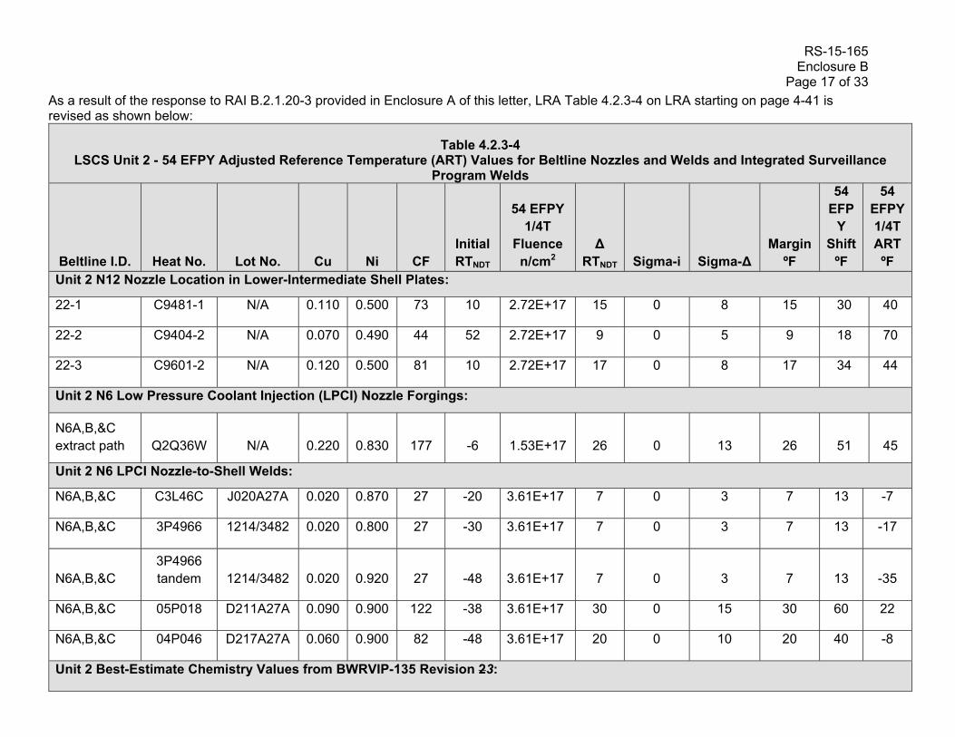
RS-15-165 Enclosure B Page 17 of 33
As a result of the response to RAI B.2.1.20-3 provided in Enclosure A of this letter, LRA Table 4.2.3-4 on LRA starting on page 4-41 is revised as shown below:
Table 4.2.3-4 LSCS Unit 2 - 54 EFPY Adjusted Reference Temperature (ART) Values for Beltline Nozzles and Welds and Integrated Surveillance
Program Welds
Beltline I.D. Heat No.
Lot No. Cu Ni CF Initial RTNDT
54 EFPY 1/4T
Fluence n/cm2
∆ RTNDT Sigma-i Sigma-∆
Margin ºF
54 EFP
Y Shift
ºF
54 EFPY 1/4T ART ºF
Unit 2 N12 Nozzle Location in Lower-Intermediate Shell Plates:
22-1 C9481-1 N/A 0.110 0.500 73 10 2.72E+17 15 0 8 15 30 40
22-2 C9404-2 N/A 0.070 0.490 44 52 2.72E+17 9 0 5 9 18 70
22-3 C9601-2 N/A 0.120 0.500 81 10 2.72E+17 17 0 8 17 34 44
Unit 2 N6 Low Pressure Coolant Injection (LPCI) Nozzle Forgings:
N6A,B,&C extract path Q2Q36W N/A 0.220 0.830 177 -6 1.53E+17 26 0 13 26 51 45
Unit 2 N6 LPCI Nozzle-to-Shell Welds:
N6A,B,&C C3L46C J020A27A 0.020 0.870 27 -20 3.61E+17 7 0 3 7 13 -7
N6A,B,&C 3P4966 1214/3482 0.020 0.800 27 -30 3.61E+17 7 0 3 7 13 -17
N6A,B,&C 3P4966 tandem 1214/3482 0.020 0.920 27 -48 3.61E+17 7 0 3 7 13 -35
N6A,B,&C 05P018 D211A27A 0.090 0.900 122 -38 3.61E+17 30 0 15 30 60 22
N6A,B,&C 04P046 D217A27A 0.060 0.900 82 -48 3.61E+17 20 0 10 20 40 -8
Unit 2 Best-Estimate Chemistry Values from BWRVIP-135 Revision 23:

RS-15-165 Enclosure B Page 18 of 33
Table 4.2.3-4 LSCS Unit 2 - 54 EFPY Adjusted Reference Temperature (ART) Values for Beltline Nozzles and Welds and Integrated Surveillance
Program Welds
Beltline I.D. Heat No.
Lot No. Cu Ni CF Initial RTNDT
54 EFPY 1/4T
Fluence n/cm2
∆ RTNDT Sigma-i Sigma-∆
Margin ºF
54 EFP
Y Shift
ºF
54 EFPY 1/4T ART ºF
Plate N/A N/A N/A N/A N/A N/A N/A N/A N/A N/A N/A N/A N/A
Weld: 3P4000 N/A 0.020 0.935 27 -50 6.50E+17 9 0 5 9 18 -32
Weld: 3P4966 N/A 0.025 0.913 34 -6 8.02E+17 13 1 6 13 25 19
Weld: 5P6771 N/A 0.034 0.934 46 -34 7.41E+17 17 2 8 17 33 -1
Unit 2 Integrated Surveillance Program Chemistry Values from BWRVIP-135 Revision 23:
Plate C3054-2 N/A 0.080 0.670 51 52 7.41E+17 18 0 9 18 37 89
Weld 402K9171 411L3071 0.020 0.950 27 -6 6.50E+17 9 0 5 9 18 12

RS-15-165 Enclosure B Page 19 of 33
As a result of the response to RAI B.2.1.20-3 provided in Enclosure A of this letter, Section 4.8, Docketed References, Reference 4.8.5, is revised from BWRVIP-135, Revision 2 to BWRVIP-135, Revision 3, December 2014, as shown below:
4.8 DOCKETED REFERENCES
4.8.1 USNRC Regulatory Guide 1.190, Calculational and Dosimetry Methods for Determining Pressure Vessel Neutron Fluence, March 2001
4.8.2 Letter from William H. Bateman, USNRC, to Bill Eaton, BWRVIP Chairman; Safety Evaluation of Proprietary EPRI Reports, BWRVIP RAMA Fluence Methodology Manual (BWRVIP-114), RAMA Fluence Methodology Benchmark Manual (BWRVIP-115), RAMA Fluence Methodology – Susquehanna Unit 2 Surveillance Capsule Fluence Evaluation for Cycles 1-5 (BWRVIP-117), RAMA Fluence Methodology Procedures Manual (BWRVIP-121), and Hope Creek Flux Wire Dosimeter Activation Evaluation for Cycle 1 (TWE-PSE-001-R-001)(TAC No. MB9765), dated May 13, 2005; pages 1 and 2 and Section 4.2, pages 9-10
4.8.3 BWRVIP-126, BWR Vessel and Internals Project, RAMA Fluence Methodology Software, Version 1.0, EPRI, Palo Alto, CA, 2003, 1007823
4.8.4 USNRC Regulatory Guide 1.99, Radiation Embrittlement of Reactor Vessel Materials, Revision 2, May 1988
4.8.5 BWRVIP-135, BWR Vessel and Internals Project, Integrated Surveillance Program (ISP) Data Source Book and Plant Evaluations, Revision 23, December 2014
4.8.6 Not Used
4.8.7 USNRC Generic Letter 98-05, Boiling Water Reactor Licensees Use of the BWRVIP-05 Report to Request Relief From Augmented Examination Requirements on Reactor Pressure Vessel Circumferential Shell Welds, November 10, 1998
4.8.8 BWRVIP-05, BWR Vessel and Internals Project, BWR Reactor Pressure Vessel Shell Weld Inspection Recommendations (BWRVIP-05), September 1995
4.8.9 BWRVIP-05 SER (Final), USNRC letter from Gus C. Lainas to Carl Terry, Niagara Mohawk Power Company, BWRVIP Chairman, Final Safety Evaluation of the BWR Vessel and Internals Project BWRVIP-05 Report, (TAC No. M93925), July 28, 1998
4.8.10 NEDO-10029, An Analytical Study on Brittle Fracture of GE-BWR Vessel Subject to the Design Basis Accident, 1969
4.8.11 Ranganath, S., "Fracture Mechanics Evaluation of a Boiling Water Reactor Vessel Following a Postulated Loss of Coolant Accident", Fifth International Conference on Structural Mechanics in Reactor Technology, Berlin, Germany, August 1979, Paper Gi/5

RS-15-165 Enclosure B Page 20 of 33 4.8.12 American Society of Mechanical Engineers (ASME) Boiler and Pressure Vessel
Code, Section XI, Rules for In-Service Inspection of Nuclear Power Plant Components, Appendix G, Fracture Toughness Criteria for Protection Against Failure, 1998 Edition including 2000 Addenda

RS-15-165 Enclosure B Page 21 of 33 As a result of the response to RAI 3.3.2.1.11-1 provided in Enclosure A of this letter, LRA Section 3.2.2.1.3 on page 3.2-4 of the LRA is revised as follows: 3.2.2.1.3 Reactor Core Isolation Cooling System
Materials
The materials of construction for the Reactor Core Isolation Cooling System components are: Carbon Steel
Carbon Steel (with internal coating)
Carbon and Low Alloy Steel Bolting
Carbon or Low Alloy Steel with Stainless Steel Cladding
Copper Alloy with 15% Zinc or More
Copper Alloy with less than 15% Zinc
Glass
Gray Cast Iron
Nickel Alloy
Stainless Steel
Stainless Steel Bolting
Zinc
Environments
The Reactor Core Isolation Cooling System components are exposed to the following environments: Air - Indoor Uncontrolled
Air – Outdoor
Concrete
Condensation
Lubricating Oil
Soil
Steam
Treated Water

RS-15-165 Enclosure B Page 22 of 33
As a result of the response to RAI 3.3.2.1.11-1 provided in Enclosure A of this letter, LRA Table 3.2.1 on page 3.2-27 of the LRA is revised as follows:
Table 3.2.1 Summary of Aging Management Evaluations for the Engineered Safety Features
Item Number
Component Aging Effect/Mechanism
Aging Management Programs
Further Evaluation Recommended
Discussion
3.2.1-53 Stainless steel, nickel alloy piping, piping components, and piping elements exposed to soil or concrete
Loss of material due to pitting and crevice corrosion
Chapter XI.M41, "Buried and Underground Piping and Tanks"
No Consistent with NUREG-1801. The Buried and Underground Piping (B.2.1.28) program will be used to manage loss of material of the stainless steel piping, piping components, and piping elements exposed to soil or concrete in the Reactor Core Isolation Cooling System.
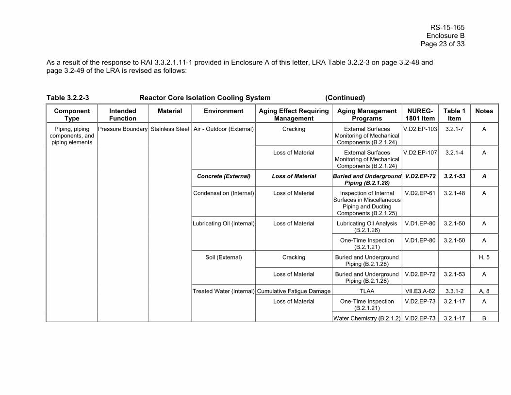
RS-15-165 Enclosure B Page 23 of 33
As a result of the response to RAI 3.3.2.1.11-1 provided in Enclosure A of this letter, LRA Table 3.2.2-3 on page 3.2-48 and page 3.2-49 of the LRA is revised as follows:
Table 3.2.2-3 Reactor Core Isolation Cooling System (Continued)
Component Type
Intended Function
Material Environment Aging Effect Requiring Management
Aging Management Programs
NUREG-1801 Item
Table 1 Item
Notes
Piping, piping components, and piping elements
Pressure Boundary
Stainless Steel
Air - Outdoor (External)
Cracking External Surfaces Monitoring of Mechanical Components (B.2.1.24)
V.D2.EP-103 3.2.1-7 A
Loss of Material External Surfaces Monitoring of Mechanical Components (B.2.1.24)
V.D2.EP-107 3.2.1-4 A
Concrete (External) Loss of Material Buried and Underground Piping (B.2.1.28)
V.D2.EP-72 3.2.1-53 A
Condensation (Internal) Loss of Material Inspection of Internal Surfaces in Miscellaneous
Piping and Ducting Components (B.2.1.25)
V.D2.EP-61 3.2.1-48 A
Lubricating Oil (Internal)
Loss of Material
Lubricating Oil Analysis (B.2.1.26)
V.D1.EP-80 3.2.1-50 A
One-Time Inspection (B.2.1.21)
V.D1.EP-80 3.2.1-50 A
Soil (External)
Cracking Buried and Underground Piping (B.2.1.28)
H, 5
Loss of Material Buried and Underground Piping (B.2.1.28)
V.D2.EP-72 3.2.1-53 A
Treated Water (Internal)
Cumulative Fatigue Damage TLAA VII.E3.A-62 3.3.1-2 A, 8
Loss of Material
One-Time Inspection (B.2.1.21)
V.D2.EP-73 3.2.1-17 A
Water Chemistry (B.2.1.2) V.D2.EP-73 3.2.1-17 B

RS-15-165 Enclosure B Page 24 of 33 As a result of the response to RAI 3.3.2.1.11-1 provided in Enclosure A of this letter, LRA Sections 3.3.2.1.8 on page 3.3-10 and page 3.3-11 of the LRA is revised as follows: 3.3.2.1.8 Diesel Generator and Auxiliaries System
Materials
The materials of construction for the Diesel Generator and Auxiliaries System components are: Aluminum Alloy
Carbon Steel
Carbon and Low Alloy Steel Bolting
Copper Alloy with 15% Zinc or More
Copper Alloy with less than 15% Zinc
Ductile Cast Iron
Elastomers
Glass
Gray Cast Iron
Stainless Steel
Stainless Steel Bolting
Environments
The Diesel Generator and Auxiliaries System components are exposed to the following environments: Air - Indoor Uncontrolled
Air - Outdoor
Closed Cycle Cooling Water
Concrete
Condensation
Diesel Exhaust
Fuel Oil
Lubricating Oil
Soil
Waste Water

RS-15-165 Enclosure B Page 25 of 33 As a result of the response to RAI 3.3.2.1.11-1 provided in Enclosure A of this letter, LRA Table 3.3.1 on page 3.3-79 of the LRA is revised as follows:
Table 3.3.1 Summary of Aging Management Evaluations for the Auxiliary Systems
Item Number
Component Aging Effect/ Mechanism
Aging Management Programs
Further Evaluation Recommended
Discussion
3.3.1-104 HDPE, Fiberglass Piping, piping components, and piping elements exposed to Soil or concrete
Cracking, blistering, change in color due to water absorption
Chapter XI.M41, "Buried and Underground Piping and Tanks"
No Not Applicable.
There are no HDPE, fiberglass piping, piping components, and piping elements exposed to soil or concrete in Auxiliary Systems.
3.3.1-105 Concrete cylinder piping, Asbestos cement pipe Piping, piping components, and piping elements exposed to Soil or concrete
Cracking, spalling, corrosion of rebar due to exposure of rebar
Chapter XI.M41, "Buried and Underground Piping and Tanks"
No Not Applicable.
There are no concrete cylinder piping, asbestos cement pipe piping, piping components, and piping elements exposed to soil or concrete in Auxiliary Systems.
3.3.1-106 Steel (with coating or wrapping) Piping, piping components, and piping elements exposed to Soil or concrete
Loss of material due to general, pitting, crevice, and microbiologically-influenced corrosion
Chapter XI.M41, "Buried and Underground Piping and Tanks"
No Consistent with NUREG-1801. The Buried and Underground Piping (B.2.1.28) program will be used to manage loss of material of carbon steel, ductile cast iron, and gray cast iron piping, piping components, and piping elements exposed to soil or concrete in the Diesel Generator and Auxiliaries System, Essential Cooling Water System, Fire Protection System, and Nonessential Cooling Water System.

RS-15-165 Enclosure B Page 26 of 33 As a result of the response to RAI 3.3.2.1.11-1 provided in Enclosure A of this letter, LRA Table 3.3.2-8 on page 3.3-133 and page 3.3-134 of the LRA is revised as follows:
Table 3.3.2-8 Diesel Generator and Auxiliaries System (Continued)
Component Type
Intended Function
Material Environment Aging Effect Requiring
Management
Aging Management Programs
NUREG-1801 Item
Table 1 Item
Notes
Piping, piping components, and piping elements
Pressure Boundary
Carbon Steel Closed Cycle Cooling Water (Internal)
Loss of Material Closed Treated Water Systems (B.2.1.13)
VII.C2.AP-202 3.3.1-45 A
Concrete (External) Loss of Material Buried and Underground Piping (B.2.1.28)
VII.H1.AP-198 3.3.1-106 A
Condensation (Internal) Loss of Material Inspection of Internal Surfaces in Miscellaneous
Piping and Ducting Components (B.2.1.25)
VII.H2.A-23 3.3.1-89 A
Diesel Exhaust (Internal)
Cumulative Fatigue Damage
TLAA H, 1
Diesel Exhaust (Internal) Loss of Material Inspection of Internal Surfaces in Miscellaneous
Piping and Ducting Components (B.2.1.25)
VII.H2.AP-104 3.3.1-88 A
Fuel Oil (Internal)
Loss of Material
Fuel Oil Chemistry (B.2.1.19)
VII.H1.AP-105 3.3.1-70 A
One-Time Inspection (B.2.1.21)
VII.H1.AP-105 3.3.1-70 A
Lubricating Oil (Internal)
Loss of Material
Lubricating Oil Analysis (B.2.1.26)
VII.H2.AP-127 3.3.1-97 A
One-Time Inspection (B.2.1.21)
VII.H2.AP-127 3.3.1-97 A
Soil (External) Loss of Material Buried and Underground Piping (B.2.1.28)
VII.H1.AP-198 3.3.1-106 A

RS-15-165 Enclosure B Page 27 of 33 As a result of the response to RAI 3.3.2.1.11-1 provided in Enclosure A of this letter, LRA Sections 3.3.2.1.12 on page 3.3-15 and page 3.3-16 of the LRA is revised as follows:
3.3.2.1.12 Fire Protection System
Materials
The materials of construction for the Fire Protection System components are: Aluminum Silicate
Calcium Silicate
Carbon Steel
Carbon and Low Alloy Steel Bolting
Ceramic Fiber
Concrete Block
Copper Alloy with less than 15% Zinc
Ductile Cast Iron
Elastomers
Galvanized Steel
Glass
Gray Cast Iron
Grout
Gypsum
Mineral Fiber
Pyrocrete
Reinforced Concrete
Stainless Steel
Stainless Steel Bolting
Environments
The Fire Protection System components are exposed to the following environments: Air - Indoor Uncontrolled
Air - Outdoor
Air/Gas – Dry
Concrete
Condensation

RS-15-165 Enclosure B Page 28 of 33
Diesel Exhaust
Raw Water
Soil

RS-15-165 Enclosure B Page 29 of 33
As a result of the response to RAI 3.3.2.1.11-1 provided in Enclosure A of this letter, LRA Table 3.3.2-12 on page 3.3-165 of the LRA is revised as follows:
Table 3.3.2-12 Fire Protection System (Continued)
Component Type
Intended Function
Material Environment Aging Effect Requiring
Management
Aging Management Programs
NUREG-1801 Item
Table 1 Item
Notes
Piping, piping components,
and piping elements
Pressure Boundary
Carbon Steel
Air - Indoor Uncontrolled (External)
Loss of Material
External Surfaces Monitoring of Mechanical Components (B.2.1.24)
VII.I.A-77 3.3.1-78 A
Fire Protection (B.2.1.16) VII.G.AP-150 3.3.1-58 A, 9
Air - Outdoor (External) Loss of Material External Surfaces Monitoring of Mechanical Components (B.2.1.24)
VII.I.A-78 3.3.1-78 A
Air/Gas - Dry (Internal) None None VII.J.AP-6 3.3.1-121 A
Condensation (Internal) Loss of Material Fire Water System (B.2.1.17)
VII.G.A-404 3.3.1-131 B
Concrete (External) Loss of Material Buried and UndergroundPiping (B.2.1.28)
VII.G.AP-198 3.3.1-106 A
Diesel Exhaust (Internal)
Cumulative Fatigue Damage
TLAA H, 6
Loss of Material Inspection of Internal Surfaces in Miscellaneous
Piping and Ducting Components (B.2.1.25)
VII.H2.AP-104 3.3.1-88 A
Raw Water (Internal)
Loss of Material
Fire Water System (B.2.1.17)
VII.G.A-33 3.3.1-64 B
VII.G.A-400 3.3.1-127 E, 8
Soil (External) Loss of Material Buried and Underground Piping (B.2.1.28)
VII.G.AP-198 3.3.1-106 A
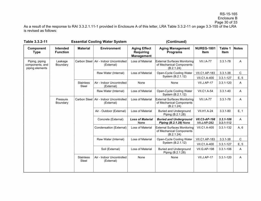
RS-15-165 Enclosure B Page 30 of 33 As a result of the response to RAI 3.3.2.1.11-1 provided in Enclosure A of this letter, LRA Table 3.3.2-11 on page 3.3-155 of the LRA is revised as follows:
Table 3.3.2-11 Essential Cooling Water System (Continued)
Component Type
Intended Function
Material Environment Aging Effect Requiring
Management
Aging Management Programs
NUREG-1801 Item
Table 1 Item
Notes
Piping, piping components, and piping elements
Leakage Boundary
Carbon Steel
Air - Indoor Uncontrolled (External)
Loss of Material External Surfaces Monitoring of Mechanical Components
(B.2.1.24)
VII.I.A-77 3.3.1-78 A
Raw Water (Internal)
Loss of Material
Open-Cycle Cooling Water System (B.2.1.12)
VII.C1.AP-183 3.3.1-38 C
VII.C1.A-400 3.3.1-127 E, 5
Stainless Steel
Air - Indoor Uncontrolled (External)
None None VII.J.AP-17 3.3.1-120 A
Raw Water (Internal) Loss of Material Open-Cycle Cooling Water System (B.2.1.12)
VII.C1.A-54 3.3.1-40 A
Pressure Boundary
Carbon Steel
Air - Indoor Uncontrolled (External)
Loss of Material External Surfaces Monitoring of Mechanical Components
(B.2.1.24)
VII.I.A-77 3.3.1-78 A
Air - Outdoor (External) Loss of Material Buried and Underground Piping (B.2.1.28)
VII.H1.A-24 3.3.1-80 E, 1
Concrete (External) Loss of Material None
Buried and Underground Piping (B.2.1.28) None
VII.C3-AP-198 VII.J.AP-282
3.3.1-106 3.3.1-112
A
Condensation (External) Loss of Material External Surfaces Monitoring of Mechanical Components
(B.2.1.24)
VII.C1.A-405 3.3.1-132 A, 6
Raw Water (Internal)
Loss of Material
Open-Cycle Cooling Water System (B.2.1.12)
VII.C1.AP-183 3.3.1-38 C
VII.C1.A-400 3.3.1-127 E, 5
Soil (External) Loss of Material Buried and Underground Piping (B.2.1.28)
VII.G.AP-198 3.3.1-106 A
Stainless Steel
Air - Indoor Uncontrolled (External)
None None VII.J.AP-17 3.3.1-120 A
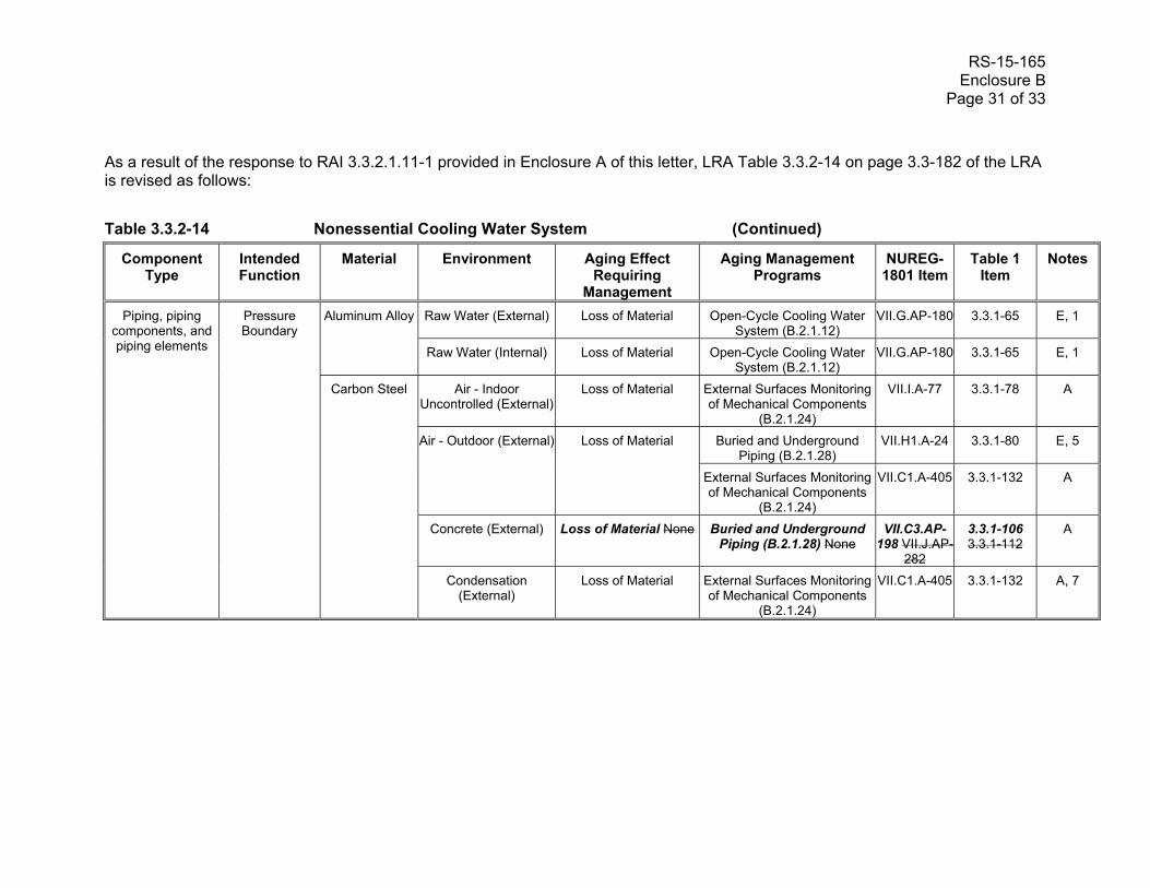
RS-15-165 Enclosure B Page 31 of 33
As a result of the response to RAI 3.3.2.1.11-1 provided in Enclosure A of this letter, LRA Table 3.3.2-14 on page 3.3-182 of the LRA is revised as follows:
Table 3.3.2-14 Nonessential Cooling Water System (Continued)
Component Type
Intended Function
Material Environment Aging Effect Requiring
Management
Aging Management Programs
NUREG-1801 Item
Table 1 Item
Notes
Piping, piping components, and piping elements
Pressure Boundary
Aluminum Alloy
Raw Water (External) Loss of Material Open-Cycle Cooling Water System (B.2.1.12)
VII.G.AP-180 3.3.1-65 E, 1
Raw Water (Internal) Loss of Material Open-Cycle Cooling Water System (B.2.1.12)
VII.G.AP-180 3.3.1-65 E, 1
Carbon Steel
Air - Indoor Uncontrolled (External)
Loss of Material External Surfaces Monitoring of Mechanical Components
(B.2.1.24)
VII.I.A-77 3.3.1-78 A
Air - Outdoor (External)
Loss of Material
Buried and Underground Piping (B.2.1.28)
VII.H1.A-24 3.3.1-80 E, 5
External Surfaces Monitoring of Mechanical Components
(B.2.1.24)
VII.C1.A-405 3.3.1-132 A
Concrete (External) Loss of Material None Buried and Underground Piping (B.2.1.28) None
VII.C3.AP-198 VII.J.AP-
282
3.3.1-106 3.3.1-112
A
Condensation (External)
Loss of Material External Surfaces Monitoring of Mechanical Components
(B.2.1.24)
VII.C1.A-405 3.3.1-132 A, 7
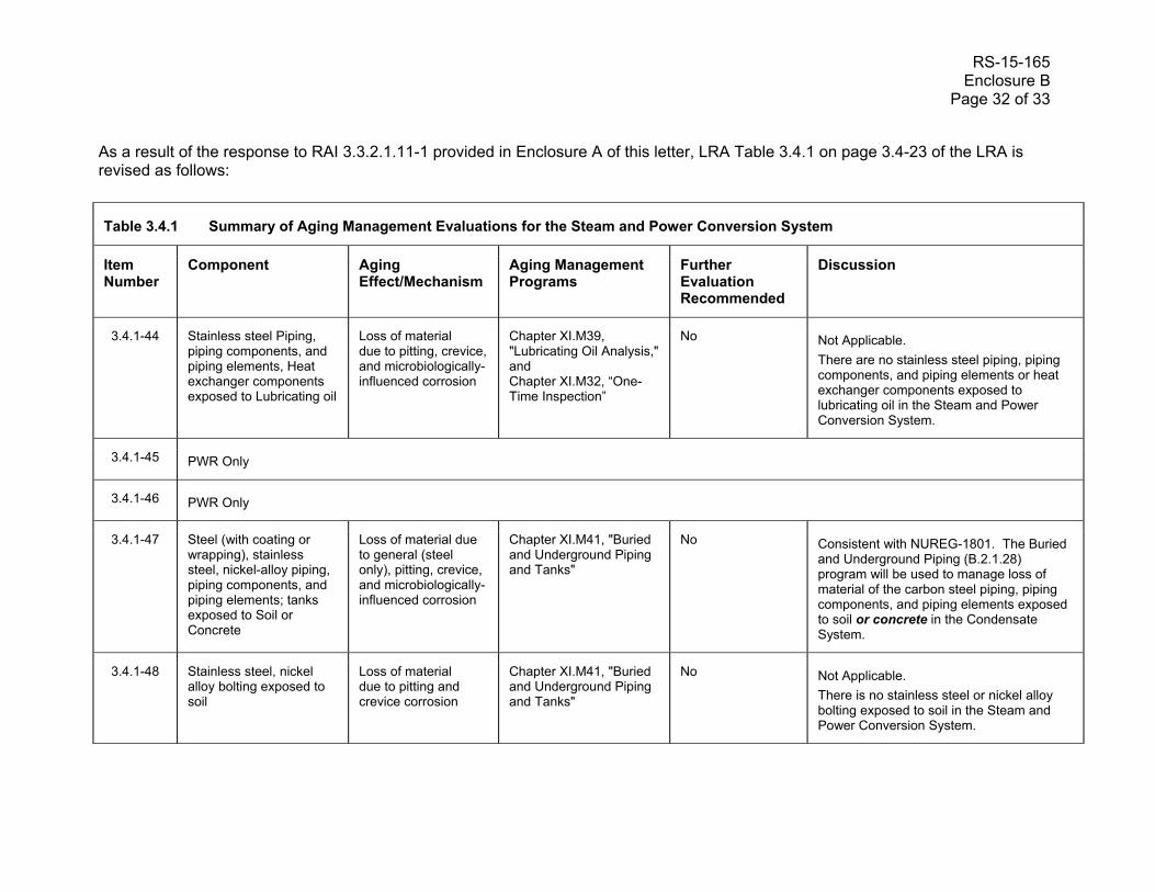
RS-15-165 Enclosure B Page 32 of 33
As a result of the response to RAI 3.3.2.1.11-1 provided in Enclosure A of this letter, LRA Table 3.4.1 on page 3.4-23 of the LRA is revised as follows:
Table 3.4.1 Summary of Aging Management Evaluations for the Steam and Power Conversion System
Item Number
Component Aging Effect/Mechanism
Aging Management Programs
Further Evaluation Recommended
Discussion
3.4.1-44 Stainless steel Piping, piping components, and piping elements, Heat exchanger components exposed to Lubricating oil
Loss of material due to pitting, crevice, and microbiologically-influenced corrosion
Chapter XI.M39, "Lubricating Oil Analysis," and Chapter XI.M32, “One-Time Inspection”
No Not Applicable.
There are no stainless steel piping, piping components, and piping elements or heat exchanger components exposed to lubricating oil in the Steam and Power Conversion System.
3.4.1-45 PWR Only
3.4.1-46 PWR Only
3.4.1-47 Steel (with coating or wrapping), stainless steel, nickel-alloy piping, piping components, and piping elements; tanks exposed to Soil or Concrete
Loss of material due to general (steel only), pitting, crevice, and microbiologically-influenced corrosion
Chapter XI.M41, "Buried and Underground Piping and Tanks"
No Consistent with NUREG-1801. The Buried and Underground Piping (B.2.1.28) program will be used to manage loss of material of the carbon steel piping, piping components, and piping elements exposed to soil or concrete in the Condensate System.
3.4.1-48 Stainless steel, nickel alloy bolting exposed to soil
Loss of material due to pitting and crevice corrosion
Chapter XI.M41, "Buried and Underground Piping and Tanks"
No Not Applicable.
There is no stainless steel or nickel alloy bolting exposed to soil in the Steam and Power Conversion System.
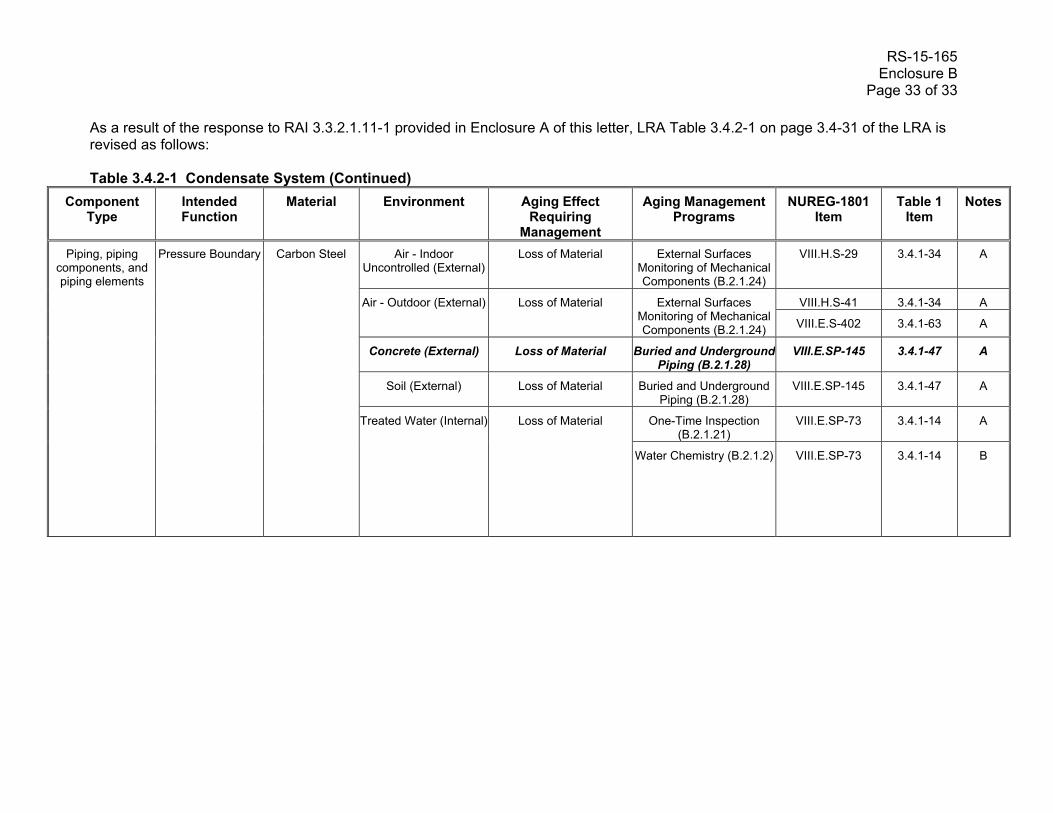
RS-15-165 Enclosure B Page 33 of 33 As a result of the response to RAI 3.3.2.1.11-1 provided in Enclosure A of this letter, LRA Table 3.4.2-1 on page 3.4-31 of the LRA is revised as follows: Table 3.4.2-1 Condensate System (Continued)
Component Type
Intended Function
Material Environment Aging Effect Requiring
Management
Aging Management Programs
NUREG-1801 Item
Table 1 Item
Notes
Piping, piping components, and piping elements
Pressure Boundary
Carbon Steel
Air - Indoor Uncontrolled (External)
Loss of Material External Surfaces Monitoring of Mechanical Components (B.2.1.24)
VIII.H.S-29 3.4.1-34 A
Air - Outdoor (External)
Loss of Material
External Surfaces Monitoring of Mechanical Components (B.2.1.24)
VIII.H.S-41 3.4.1-34 A
VIII.E.S-402 3.4.1-63 A
Concrete (External) Loss of Material Buried and Underground Piping (B.2.1.28)
VIII.E.SP-145 3.4.1-47 A
Soil (External) Loss of Material Buried and Underground Piping (B.2.1.28)
VIII.E.SP-145 3.4.1-47 A
Treated Water (Internal)
Loss of Material
One-Time Inspection (B.2.1.21)
VIII.E.SP-73 3.4.1-14 A
Water Chemistry (B.2.1.2) VIII.E.SP-73 3.4.1-14 B