Embed Size (px)
Citation preview
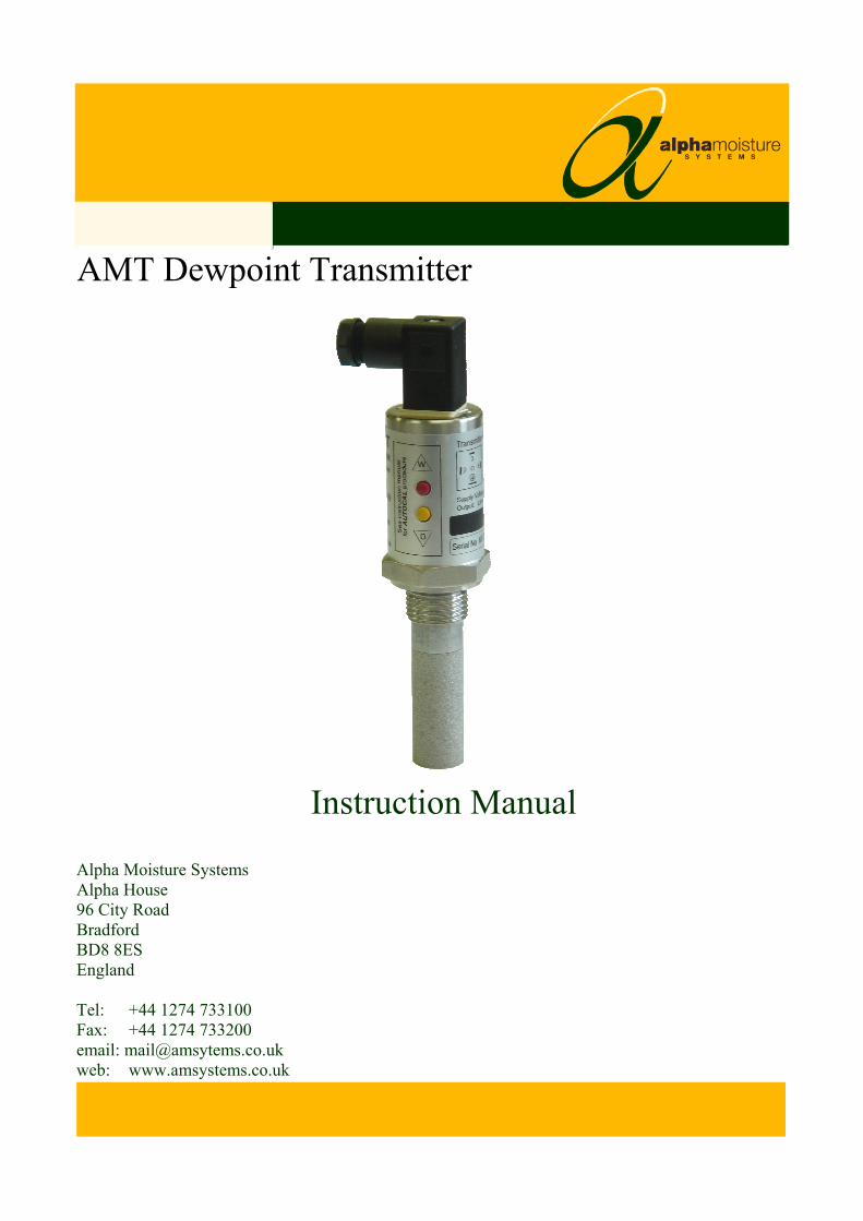
AMT Dewpoint Transmitter
Instruction Manual
Alpha Moisture Systems Alpha House 96 City Road Bradford BD8 8ES England Tel: +44 1274 733100 Fax: +44 1274 733200 email: [email protected] web: www.amsystems.co.uk
AMT Dewpoint Transmitter
Instruction Manual
Issue 4 07/03/2011 1527 AMT User Manual
Index
1 Overview........................................................................................................................... 1 1.1 Gas Compatibilities ...............................................................................................................................1
2 Installing the AMT in a Air/Gas Sampling System...................................................... 2 2.1 Piping installation ..................................................................................................................................2 2.2 Component Index ..................................................................................................................................3 2.3 Installing and Commissioning the Model AMT Transmitter.................................................................3 2.4 Wiring the AMT ....................................................................................................................................4 2.5 Connector Pins.......................................................................................................................................4
3 Normal Operation ........................................................................................................... 5 3.1 Analogue 4-20mA Mode (2-wire) .........................................................................................................5
4 Autocal.............................................................................................................................. 5 4.1 Pre-conditioning the transmitter ............................................................................................................5 4.1 Entering Autocal Mode .........................................................................................................................6 4.2 Adjust the autocal ..................................................................................................................................6 4.3 Completing the autocal ..........................................................................................................................6 4.4 AMT Range AutoCal Method Lookup Table........................................................................................6
5 Faults/Errors.................................................................................................................... 8
6 AMT Specification........................................................................................................... 8
7 Appendix A – AMT with Connector, General Arrangement...................................... 9
8 Appendix B – Transmitter Holder General Arrangement ........................................ 10
1 Overview The Model AMT Dewpoint Hygrometer is a 2 wire 4-20mA loop powered transmitter, used for continuous measurement of moisture in a process gas or compressed air. The Model AMT transmitter can be factory configured to output a 4-20mA linear signal for any of the following moisture units:- ºC or ºF dewpoint, ppm(v), ppb(v), g/m3, and lb/MMSCF. The ultra high capacitance sensing element is long lasting and offers excellent sensitivity, repeatability and response speed. Each unit is calibrated, traceable to International Humidity Standards, and is supplied with a Certificate of Calibration guaranteeing accuracy to ± 2ºC dew point. The transmitter also incorporates an Automatic Calibration (AUTOCAL) feature, which allows the user to carry out field calibration / span check. The AUTOCAL feature is operated by means of two small buttons built into the transmitter body. To avoid accidental corruption, the buttons are locked in normal operation and can only be activated by following a specific routine. The RISC microprocessor circuitry of the Model AMT transmitter allows high resolution with advanced self-diagnostics for fault conditions. It also enables periodic re-calibration of the moisture sensor, storing calibration data within the fully self-contained unit. Loop powered, by a 7v to 28v dc source. The Model AMT transmitter will provide the user with a linear 4-20mA signal over the chosen range. The mechanics of the Model AMT transmitter have been designed to cope with extreme environmental conditions. The rugged stainless steel construction offers protection to IP66 (NEMA4X), with the transmitter electrical connections made via secure industrial type connector (size C, DIN EN 175301). The AMT transmitter can withstand 35,000 kPa (350bar) maximum pressure and by employing low resistance cable, the transmitter can be located at significant distances, in excess of 1000 meters, from the data collection point. Designed with the operator in mind, for reliable and accurate measurements, the Model AMT is extremely easy to install and operate, requiring little or no maintenance.
1.1 Gas Compatibilities The Model AMT sensing elements are Al2O3 and therefore suitable for many different industrial and research applications. Most gases can be checked for their moisture content with no need for the calibration to be altered when changing between different gases, as the sensor operates only with reference to the water vapour content. However, some gases must be avoided, as they are not compatible with the material used in the construction of the sensor. Ammonia (NH3) and chlorine (Cl) must be avoided at all times, even in small quantities. Hydrogen chloride (HCl) also attacks the sensors very quickly. Some, less aggressive, acidic gases, such as sulphur dioxide (SO2), can be monitored, as long as the moisture content is low, generally less than 100ppm(v). If in doubt, please ask your supplier. Sulphur hexaflouride (SF6) has no effect on the sensor. If the gas has been exposed to arcing, however, it is possible that various acidic species will have been formed that will corrode the sensor. When testing SF6 that may have been arced, therefore, an acidity test should be carried out first; if the gas proves to be acidic then the moisture test should not be carried out.
It is strongly recommended that the sample should not contain particulate matter, oil or other heavy hydrocarbon condensate. If these components contaminate the sample system and/or the measuring sensor, the system response time will be lengthened, although the sensor calibration will not be effected.
Page 1
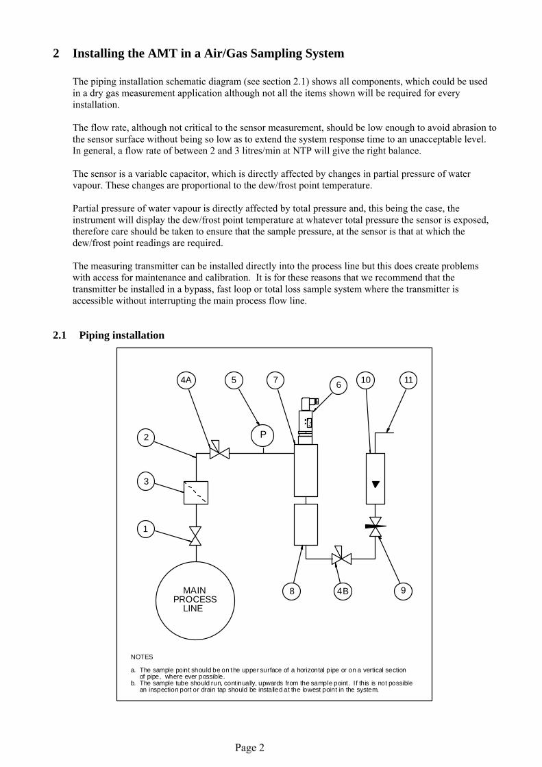
2 Installing the AMT in a Air/Gas Sampling System The piping installation schematic diagram (see section 2.1) shows all components, which could be used in a dry gas measurement application although not all the items shown will be required for every installation. The flow rate, although not critical to the sensor measurement, should be low enough to avoid abrasion to the sensor surface without being so low as to extend the system response time to an unacceptable level. In general, a flow rate of between 2 and 3 litres/min at NTP will give the right balance. The sensor is a variable capacitor, which is directly affected by changes in partial pressure of water vapour. These changes are proportional to the dew/frost point temperature. Partial pressure of water vapour is directly affected by total pressure and, this being the case, the instrument will display the dew/frost point temperature at whatever total pressure the sensor is exposed, therefore care should be taken to ensure that the sample pressure, at the sensor is that at which the dew/frost point readings are required. The measuring transmitter can be installed directly into the process line but this does create problems with access for maintenance and calibration. It is for these reasons that we recommend that the transmitter be installed in a bypass, fast loop or total loss sample system where the transmitter is accessible without interrupting the main process flow line.
2.1 Piping installation
P
1
3
2
4A 5 7 6 10 11
94B8 MAINPROCESS LINE
NOTES
a. The sample point should be on the upper surface of a horizontal pipe or on a vertical section of pipe, where ever possible.b. The sample tube should run, cont inually, upwards from the sample point . I f this is not possible an inspection port or drain tap should be installed at the lowest point in the system.
Page 2
2.2 Component Index 1) Sample Isolation Valve - This is a recommended item as it allows access to the sample system without
interrupting the main process line. 2) Sample Tube – This should be stainless steel for dry air or gas applications but copper or carbon steel can be
used where wetter gases are to be measured. If any section of the sample tube must be flexible then PTFE should be used. In most cases, 3mm OD (1/8”) is sufficient as it provides good system response time within minimum flow. 6mm OD (1/4”) tube can be used where pressure drops across the 3mm tube are too high
3) Filter Unit – A filter unit is recommended when the samples are likely to contain particulate matter. If the air/gas sample contains heavy hydrocarbon condensate, the filter must be of the coalescing type with a drain. The filter unit should be positioned as close to the sample point as practical.
4) Pressure Reduction Valve or Pressure Regulator – If the sample is to be measured at atmospheric pressure then the valve 4A should be fitted and 4B omitted from the system. If the sample is to be measured, at full line pressure and the exhaust vented to atmosphere, then valve 4B should be fitted and 4A omitted from the system. If measurements are to be taken at full line pressure and the sample is to be returned to a part of the main line or a vent, which is at a pressure higher than atmospheric, and the input to that line needs a controlled pressure then both 4A and 4B will be required.
5) Sample Pressure Gauge – This is not a critical part of the moisture measurement but may be required if Dew/Frost point measurements are to be made at higher than atmospheric pressure.
6) Measuring Transmitter, see “Appendix A – AMT with Connector, General Arrangement”. 7) Transmitter Holder, see “Appendix B – Transmitter Holder General Arrangement”. 8) Desiccant Chamber – This item is required when the sampling is to be intermittent. When installed it
prevents the ingress of wet air to the sample system, while the sample is not flowing, improving the response time.
9) Flow Control Valve – This can be a separate item or combined with the flow indicator. 10) Flow Indicator – The recommended sample flow is 2 to 3 SL/M. 11) Sample Exhaust – The exhaust can be vented to atmosphere or returned to the process line as discussed
above.
2.3 Installing and Commissioning the Model AMT Transmitter It is advisable to carry out an initial purge routine of the sample loop, before installing the transmitter, in order to remove the possibility of sensor damage on start-up. Refer to the sample system schematic in section 2.1. Open the inlet isolation valve slowly, until a small flow of air/gas at atmospheric pressure flows through the inlet pipe work to the transmitter holder and exhausts through the sensor entry port of the transmitter holder. Allow this purge to continue for about 15 to 20 minutes to remove any residual moisture from the sample pipe work and components. Close the inlet isolation valve and install the transmitter into the transmitter holder. Locate and secure the four-pin transmitter cable connector in positioned on the transmitter. Use the locking screw in order to affect a weatherproof seal. Open the inlet valve slowly, again and, by opening all valves after the transmitter holder, allow a low-pressure purge through the whole sample system. (Note. If a closed by-pass loop is installed, this section of the procedure is not possible). Set the required pressures and flows within the sample loop. This completes the installation and commissioning but, on initial start-up, it could take several hours for the system to reach equilibrium.
Page 3
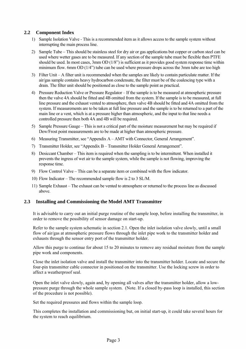
2.4 Wiring the AMT The AMT is a 2-Wire 4-20mA transmitter. Typical electrical connection to generate a voltage output is shown below:
POW E R S U P P L Y +1 2 V t o + 2 8 V
4 - 2 0mA Signal
+Vs
0V
P i n 1 Pin 2
SENSERESISTOR
A M T
Rs
Vout
V o u t m a x = R s x 2 0 x 1 0 - 3
Note, the maximum value for Rs in this circuit can be calculated by the formula: Rs max = [40 x (Vs – 7) ]Ω. If the wiring resistance is expected to be more than a few percent of the value of Rs, then this resistance must be taken away from the answer to get the maximum usable value of Rs.
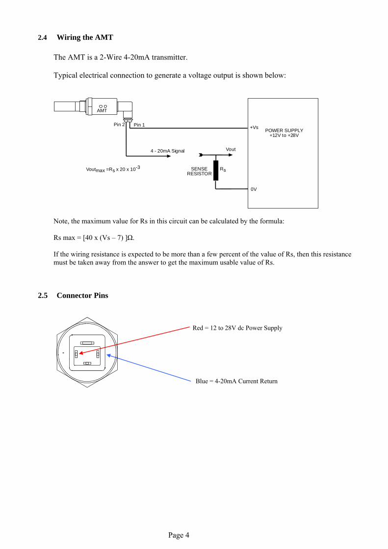
2.5 Connector Pins
Red = 12 to 28V dc Power Supply
Blue = 4-20mA Current Return
Page 4
3 Normal Operation
3.1 Analogue 4-20mA Mode (2-wire) In normal operation, the transmitter will produce a 4-20mA signal, which is proportional to the level of moisture in the gas being monitored. The moisture reading is sampled and up dated once per second. The AMT has 3020 distinct steps over the 4 to 20mA range corresponding to a resolution of 0.005mA.
4 Autocal
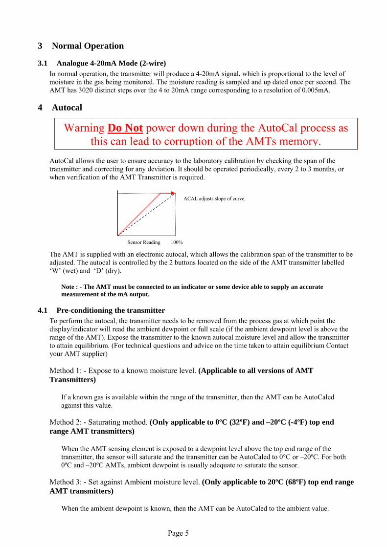
AutoCal allows the user to ensure accuracy to the laboratory calibration by checking the span of the transmitter and correcting for any deviation. It should be operated periodically, every 2 to 3 months, or when verification of the AMT Transmitter is required.
The AMT is supplied with an electronic autocal, which allows the calibration span of the transmitter to be adjusted. The autocal is controlled by the 2 buttons located on the side of the AMT transmitter labelled ‘W’ (wet) and ‘D’ (dry).
Note : - The AMT must be connected to an indicator or some device able to supply an accurate measurement of the mA output.
Warning Do Not power down during the AutoCal process as this can lead to corruption of the AMTs memory.
ACAL adjusts slope of curve.
Sensor Reading 100%
4.1 Pre-conditioning the transmitter To perform the autocal, the transmitter needs to be removed from the process gas at which point the display/indicator will read the ambient dewpoint or full scale (if the ambient dewpoint level is above the range of the AMT). Expose the transmitter to the known autocal moisture level and allow the transmitter to attain equilibrium. (For technical questions and advice on the time taken to attain equilibrium Contact your AMT supplier) Method 1: - Expose to a known moisture level. (Applicable to all versions of AMT Transmitters)
If a known gas is available within the range of the transmitter, then the AMT can be AutoCaled against this value.
Method 2: - Saturating method. (Only applicable to 0ºC (32ºF) and –20ºC (-4ºF) top end range AMT transmitters)
When the AMT sensing element is exposed to a dewpoint level above the top end range of the transmitter, the sensor will saturate and the transmitter can be AutoCaled to 0°C or –20ºC. For both 0ºC and –20ºC AMTs, ambient dewpoint is usually adequate to saturate the sensor.
Method 3: - Set against Ambient moisture level. (Only applicable to 20ºC (68ºF) top end range AMT transmitters)
When the ambient dewpoint is known, then the AMT can be AutoCaled to the ambient value.
Page 5
4.1 Entering Autocal Mode
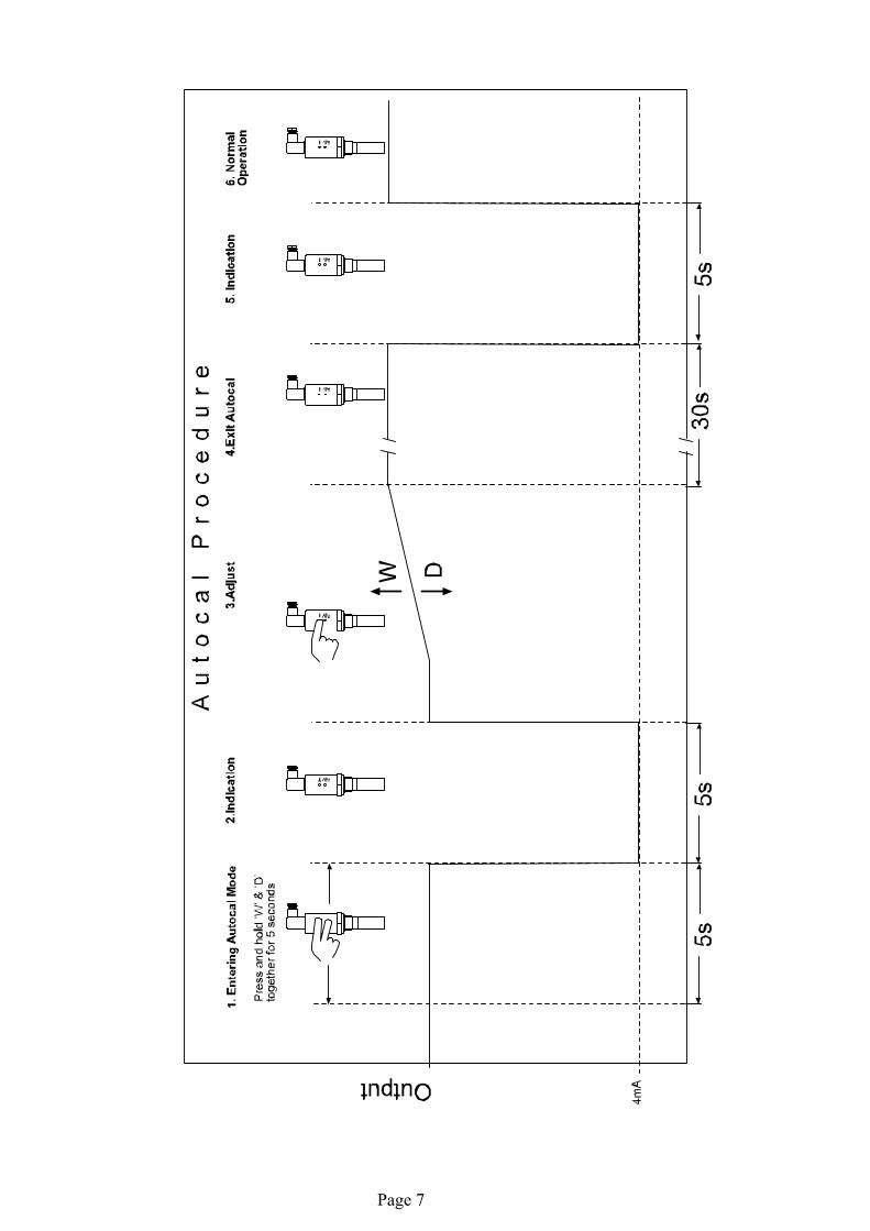
Once the transmitter has been pre-conditioned, the AutoCal Mode of the AMT can be activated. Press and hold the ‘W’ and ‘D’ buttons, simultaneously for 5 seconds. ONLY PRESS THE BUTTONS IF THE SENSOR IS PROPERLY PRE-CONDITIONED. FAILURE TO COMPLY WILL CORRUPT THE TRANSMITTERS CALIBRATION. The attached 4-20mA display will (after the 5 seconds) indicate the bottom range of the AMT (or 4mA if reading current) for 5 seconds, confirming that autocal mode has been entered. The buttons should be released once the display indicates the bottom range. After the 5 seconds delay the AMT will revert to the measured dewpoint and the buttons will be active.
4.2 Adjust the autocal
Use the ‘W’ and ‘D’ buttons to move the reading up or down so that the desired dewpoint is displayed.
Method 1: - Adjust the AMT reading until the indicator reads the known moisture level.
Method 2: - Adjust the AMT reading until the indicator reads 0°C or –20ºC whichever is applicable to the AMT being AutoCaled Method 3: - Adjust the AMT reading until the indicator reads the known ambient moisture reading.
4.3 Completing the autocal
Once the desired value is reached, the autocal process can be completed simply by leaving the buttons untouched for 30 seconds. After the 30 seconds, the display will indicate the bottom of the range for a period of 5 seconds and then the AMT will exit the autocal mode. The AMT will now output the corrected dewpoint and can be reinserted into the process. A graphical description of the autocal modes is given on the next page.
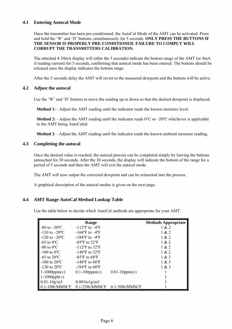
4.4 AMT Range AutoCal Method Lookup Table
Use the table below to decide which AutoCal methods are appropriate for your AMT.
Range Methods Appropriate -80 to –20ºC -112ºF to –4ºF 1 & 2 -110 to –20ºC -166ºF to –4ºF 1 & 2 -120 to –20ºC -184ºF to –4ºF 1 & 2 -65 to 0ºC -85ºF to 32ºF 1 & 2 -80 to 0ºC -112ºF to 32ºF 1 & 2 -100 to 0ºC -148ºF to 32ºF 1 & 2 -65 to 20ºC -85ºF to 68ºF 1 & 3 -100 to 20ºC -148ºF to 68ºF 1 & 3 -120 to 20ºC -184ºF to 68ºF 1 & 3 1-1000ppm(v) 0.1-100ppm(v) 0.01-10ppm(v) 1 1-1000ppb(v) 1 0.01-10g/m3 0.001to1g/m3 1 0.1-10lb/MMSCF 0.1-25lb/MMSCF 0.1-50lb/MMSCF 1
Page 6
Page 7
5 Faults/Errors
• If the sensor is short-circuited, the transmitter will produce a constant 20.75mA output. • If the sensor is open-circuited, the transmitter will produce a constant 20.50mA output. • If the hardware develops a fault, the transmitter will produce 21.0mA for 5 seconds after switch
on and then continue to give an output.
6 AMT Specification Display : Compatible with the 4-20mA DS1200 Dewpoint Meter. Output Signal : 4 to 20mA Linear Operating Voltage : 7V - 28V DC. Reverse polarity protected. Maximum Series Resistance: = 40 x (Supply Voltage – 7)Ω Sensing element : Ultra High Capacitance - Aluminium Oxide Type Autocal : Field calibration / Span check facility. Factory calibration : Supplied with Certificate of Calibration traceable to NPL / NIST Accuracy : ± 2°C dewpoint (NPL / NIST traceable for range -90°C to 20°C) Temperature compensation: Temperature compensated for operating range. Resolution : 5 µA Repeatability : Better than ±0.3ºC dewpoint Operating temperature : -20°C to +60°C Storage Temperature : -20°C to +70°C Operating Pressure : From 1kPa (0.01 barA) to Maximum 35,000kPa ( 350 barA) Operating Humidity (External): Maximum - 95% RH Non-condensing Sample Flow Rate : Independent but ideally 2 to 5 litres per minute. Max: 25 litres/min. Cable Terminations : IP66 (NEMA4X) rated, size C, DIN EN 175301 connector at the
transmitter and other end terminated with bootlace ferrules. Cable : Supplied with 2m standard cable. Nominal diameter 3.4mm, 92ohms/km. Electromagnetic Compatibility (EMC):
Immunity: Complies with EN 61000-6-1:2001 Emissions: Complies with EN 61000-6-3:2001 Warm Up Time : 10 seconds Fault Conditions : Sensor Open Circuit : Output drives to 20.50mA
Sensor Short Circuit : Output drives to 20.75mA Isolation : Sensing Element connected to the 4-20mA loop but isolated from body. Transmitter Enclosure : 316 Stainless steel body with size C, DIN EN 175301 connector. Sensor Protection : 316 Sintered stainless steel filter - 50 micron Probe Material (Wetted Parts): 316 Stainless Steel Weatherproof Classification: IP66 / NEMA4X when Connector mated to Transmitter. Mechnical Connection : 3/4” UNF (16tpi) with integral Viton “O” ring seal. Mechanical Warranty : 24 months in case of faulty workmanship and defective parts. Calibration Warranty : 12 months subject to usage. Weight : 175grams (includes connector)
Page 8
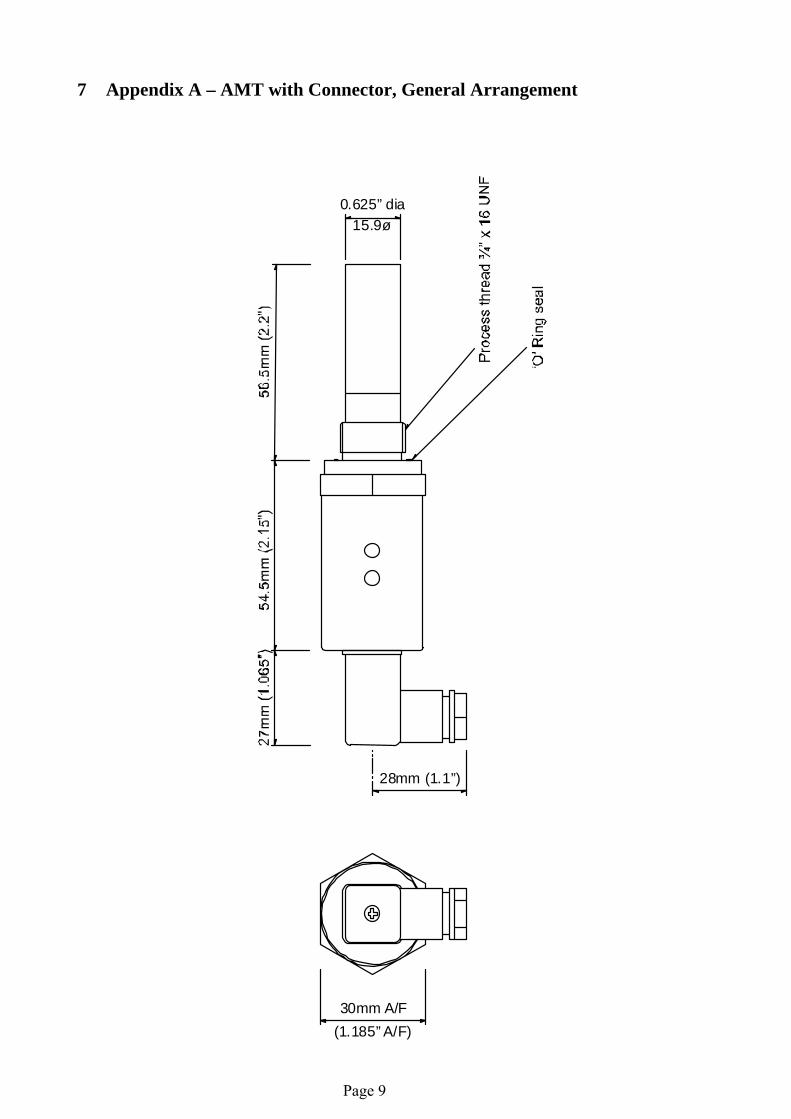
7 Appendix A – AMT with Connector, General Arrangement 30mm A/F
(1.185” A/F)
28mm (1.1”)
15.9ø0.625” dia
Page 9
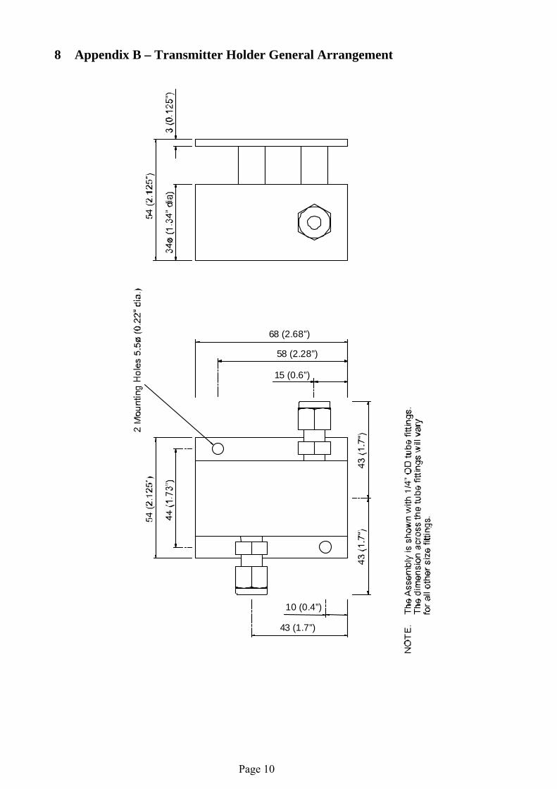
8 Appendix B – Transmitter Holder General Arrangement 15 (0.6”)
58 (2.28”)
68 (2.68”)
10 (0.4”)
43 (1.7”)
Page 10


![SHAW AUTOMATIC DEWPOINT METER MANUAL - … · SHAW AUTOMATIC DEWPOINT METER MANUAL ... drier than about -65 c. dewpoint). Then ... and slowly raise the head by hand]. 6](https://img.pdfslide.us/doc/110x75/5b4ff89e7f8b9a2a6e8d5734/shaw-automatic-dewpoint-meter-manual-shaw-automatic-dewpoint-meter-manual.jpg)