Embed Size (px)
Citation preview
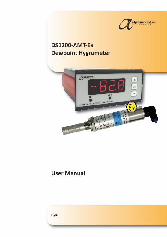
DS1200-AMT-Ex
Dewpoint Hygrometer
User Manual
English
Document Reference: 2148 - Issue 1 - 30th SEPTEMBER 2014
© Alpha Moisture Systems Ltd. 2014
This manual should be kept with the Model DS1200-AMT-Ex
Please read this manual carefully
from the beginning.
You must observe the safety information
on page 2 before installation.
Section1. Warnings and Safety Information
1.1 Definitions: 31.2 Receipt and Unpacking 31.3 Environment 31.4 Normal Operation 31.5 Cleaning 3
2. General Information 43. System Description 5
3.1 Model DS1200 53.2 Model DS1200-AMT-Ex System Application: 53.3 DS1200 Mounting: 53.4 Installing the Instrument into a Panel 5
4. Wiring 64.1 Model DS1200 Power Supply 64.2 AMT Sensor Cable 64.3 Alarm Cable 64.4 Analogue Output Cable 64.5 Rear Connections: 6Wiring continued. 74.6 For Wiring the PR5104BB2A/B Isolator to the Model AMT-Ex connection 74.7 Wiring the Model AMT-Ex to the Model DS1200 7
5. Gas Compatibilities 76. Installing the Model AMT-Ex in an air/gas sampling system 8
6.1 Piping installation Schematic 96.2 Piping schematic component index 9-10
7. Installing and Commissioning the Model AMT-Ex 10-117.1 Operation 117.2 Commissioning 127.3 Setting the Alarm Trip Points 127.3 Setting the Alarm Trip Points continued. 12-13
8. Normal Operation 148.1 Analogue 4-20mA Mode (3-wire) 148.2 Autocal 148.3 Pre-conditioning the transmitter 14-158.4 Entering Autocal Mode 158.5 Adjust the autocal 15-168.6 Completing the autocal 168.7 Model AMT-Ex Range AutoCal Method Lookup Table 168.8 Faults/Errors 17Graphical description of the autocal modes 18
9. Specifications 199.1 Model DS1200 Specifications: 199.2 Model AMT-Ex Specification 19-209.3 Single Isolator Specifications (1 and 2 Channels) 21
Mechanical specifications 21Approvals 21
9.4 Applicable Standards 219.5 Model AMT-Ex Transmitter Intrinsic Safety Certification Standards: 21
10 Appendix A – Model AMT-Ex / PR5104BB2A / Model DS1200 - Installation Schematics. 222 x Model AMT-Ex’s / PR5104BB2B / 2 x Model DS1200 ‘s 23
11 Appendix B – PR5104BB2A/B to Model AMT-Ex Connections 2412 Appendix C - Model AMT-Ex with Connector, General Arrangement 2513 Appendix D – Transmitter Holder General Arrangement 2614 Contact Information 27
Model DS1200-AMT-Ex
2148 - Iss 1 - 09/14 1
Contents
1. Warnings and Safety Information
Model 6020Model DS1200-AMT-Ex
2148 - Iss 1 - 09/142
Warning!
• The Model DS1200 is designed for connection to hazardous electric voltages.
Ignoring this warning can result in severe personal injury or mechanical damage.
To avoid the risk of electric shock and fire, the safety instructions of this manual
must be observed and the guidelines followed. The specifications must not be
exceeded, and the Model DS1200 must only be applied as described in the
following pages. Prior to commissioning of the DS1200-AMT-Ex, this manual
must be examined carefully. Only qualified personnel (technicians) should install
the Model DS1200-AMT-Ex.
• If the Model DS1200-AMT-Ex is used in a manor not specified by the manufacturer,
the protection provided by the equipment may be impaired.
Warning!
• Until the Model DS1200-AMT-Ex is installed, do not connect hazardous voltages to
the Model DS1200 display unit.
• Trouble shooting of the Model DS1200-AMT-Ex should only be carried out when
disconnected from the mains power supply and under ESD safe conditions.
• Repair of the Model DS1200-AMT-Ex must be done by Alpha Moisture Systems, or
authorised distributors, only.
Warnings!
The Model AMT-Ex is intrinsically safe and certified to ATEX and IECEx standards.
Therefore, it can be used in hazardous areas with an isolator installed in the safe area
with the Model DS1200. See pages 22 & 24 for wiring details.
It is the responsibility of the user to ascertain the suitability of the Model AMT-Ex for
use in hazardous areas. Risk assessments should be performed prior to use, taking into
account the Model AMT-Ex certifications, and the location and the gas being monitored etc.
Certification: ATEX Marking –
II 1G Ex ia IIC T4 Ex iaD IIC T4 20 T135°C ( -20°C ≤ Ta ≤ +60°C )
Certification: IECEx Marking –
IECEx BAS 07.0080 Ex ia IIC T4 Ex iaD IIC T4 20 T135°C ( -20°C ≤ Ta ≤ +60°C )
PLEASE NOTE: Throughout this manual -
“Model DS1200-AMT-Ex” is the “Dewpoint Hygrometer” (Without isolator)
“Model DS1200” is the “Display Unit”
“Model AMT-Ex” is the “Dewpoint Transmitter”
Model 6020Model DS1200-AMT-Ex
1.1 Definitions
• Hazardous voltages have been defined as the ranges: 75 to 1500 volt DC, and
50 to 1000v volt AC.
• Technicians are qualified persons educated or trained to mount, operate,
troubleshoot and technically correct in accordance with safety regulations.
• Operators are persons being familiar with the content of this manual, able to
adjust and operate the Model DS1200-AMT-Ex during normal operation.
1.2 Receipt and Unpacking
• Unpack the Model DS1200-AMT-Ex when it is ready to install and without damaging it.
Always follow the manual and ensure it is always accessible to the installer and
operator.
• Check at the receipt of the Model DS1200-AMT-Ex whether the type corresponds
to the one ordered.
1.3 Environment
• Avoid direct sunlight, dust, high temperatures, mechanical vibrations and shock,
as well as rain and heavy moisture. If avoidance of high moisture is not possible,
employ ventilation, rather than increased temperature to prevent condensation.
• The Model DS1200-AMT-Ex falls under the installation Category II, pollution
Degree 1, and Insulation Class II.
1.4 Normal Operation
• Operators are only allowed to adjust and operate the Model DS1200-AMT-Ex when
safely fixed to a panel, thus avoiding the danger of personnel injury and damage.
This means there is no electrical shock hazard, and the Model DS1200 front panel is
easily accessible.
1.5 Cleaning
• When disconnected, the Model DS1200 may be cleaned with a cloth moistened
with distilled water or ethyl alcohol.
2148 - Iss 1 - 09/14 3
Model 6020Model DS1200-AMT-Ex
2148 - Iss 1 - 09/144
2. General Information
The Model-AMT-Ex is a 3 wire 4-20mA transmitter, used for continuous measurement
of moisture in a process gas or compressed air and can be configured to output a linear
signal for any of the following moisture units:- °C or °F dewpoint, ppm(v), ppb(v), g/m3,
and lb/MMSCF.
The long lasting sensing element offers excellent sensitivity, repeatability and response
speed. Each unit is supplied with a Certificate of Calibration, traceable to International
Humidity Standards, validating accuracy to ± 2°C dew point.
Model AMT-Ex is an ATEX certified, intrinsically safe, dewpoint transmitter, for
hazardous areas when installed with the appropriate isolator such as a PR5104BB2A(&B)
in the safe area.
The transmitter also incorporates an Automatic Calibration (AUTOCAL) feature, which
allows the user to carry out field calibration / span check. The AUTOCAL feature is
operated by means of two small buttons built within the transmitter enclosure. To
avoid tamper, the buttons are locked in normal operation and can only be activated by
following a special routine described later in this manual.
The integral RISC microprocessor circuitry of the Model AMT-Ex allows high resolution
with advanced self-diagnostics for fault conditions. It also enables periodic re-calibration
of the moisture sensor, storing calibration data within the fully self-contained unit.
The mechanics of the Model AMT-Ex have been designed to cope with extreme
environmental conditions. The rugged stainless steel construction offers protection to
IP66 (NEMA4X), with the transmitter electrical connections made via secure industrial
type connector.
The Model AMT-Ex can withstand 35,000 kPa (350bar) maximum pressure and, by
employing low resistance cable, the transmitter can be located in excess of 1000 meters,
from the safe area location of the signal isolator.
Designed with the operator in mind, for reliable and accurate measurements, the
Model AMT-Ex is extremely easy to install and operate, requiring little or no maintenance.
The Model AMT-Ex is supplied with a Certificate of Calibration, an instruction
manual and 2m connection cable. Longer cables are available - See datasheet for details.
Model DS1200-AMT-Ex
2148 - Iss 1 - 09/14 5
3 System Description
3.1 Model DS1200• 4-digit 14 segment LED display• Loop powered Model AMT-Ex, Model DS1200• 2 Alarm Relays• mA Output and with a universal voltage supply
3.2 Model DS1200-AMT-Ex System Application• The Model DS1200 displays a digital readout of moisture content, derived from
the Model AMT-Ex and PR5104BB2A (or B) signal isolator.
3.3 DS1200 Mounting• Only technicians who are familiar with the technical terms, warnings, and
instructions in the manual and who are able to follow these should connect the instrument.
• Should there be any doubt as to the correct handling of the Model DS1200, please contact your local distributor.
• Mounting and connection of the Model DS1200 should comply with the national legislation for the mounting of electric materials, i.e. wire cross-section, protective fuse, and location. Descriptions of Input / Output and supply connections are shown in the block diagram on page 6 and the instrument top label.
• The maximum size of the protective fuse is 10A and, together with the power switch, it should be easily accessible and close to the Model DS1200. The powerswitch should be marked with a label indicating it will turn OFF the voltage to the Model DS1200.
• To be mounted in front panels. The included rubber packing must be mounted between the panel cutout and the display front to obtain IP65 (NEMA 4) ingress protection.
3.4 Installing the Instrument into a Panel• Make a cut-out in the donor panel 92.0/92.8 x 45.0/45.6mm (DIN 43700).• The maximum panel thickness is 10mm and, if an effective IP65 weatherproof
seal is required, the minimum recommended panel thickness is 1.6mm.• Pass the instrument cabinet through the cut-out in the donor panel and slide
the panel clamp over the instrument, from the back.• Turn the Red panel clamp screws until the instrument is clamped in position.
The screws must be tightened sufficiently to affect a seal between the front of the donor panel and the back of the instrument bezel, but never over tightened to the point of fracturing the panel clamp or instrument case.
NOTE: Wires are retained by screws. Ensure that the exposed section of the wire is fully inserted and that no loose strands are exposed.
4. Wiring
Model DS1200-AMT-Ex
2148 - Iss 1 - 09/146
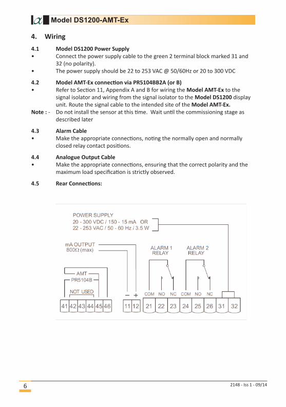
4.1 Model DS1200 Power Supply
• Connect the power supply cable to the green 2 terminal block marked 31 and
32 (no polarity).
• The power supply should be 22 to 253 VAC @ 50/60Hz or 20 to 300 VDC
4.2 Model AMT-Ex connection via PR5104BB2A (or B)
• Refer to Section 11, Appendix A and B for wiring the Model AMT-Ex to the
signal isolator and wiring from the signal isolator to the Model DS1200 display
unit. Route the signal cable to the intended site of the Model AMT-Ex.
Note : - Do not install the sensor at this time. Wait until the commissioning stage as
described later
4.3 Alarm Cable
• Make the appropriate connections, noting the normally open and normally
closed relay contact positions.
4.4 Analogue Output Cable
• Make the appropriate connections, ensuring that the correct polarity and the
maximum load specification is strictly observed.
4.5 Rear Connections:
Wiring continued.
Model DS1200-AMT-Ex
2148 - Iss 1 - 09/14 7
4.6 For wiring the PR5104BB2A/B Isolator to the Model AMT-Ex connection
See Appendix B on page 24.
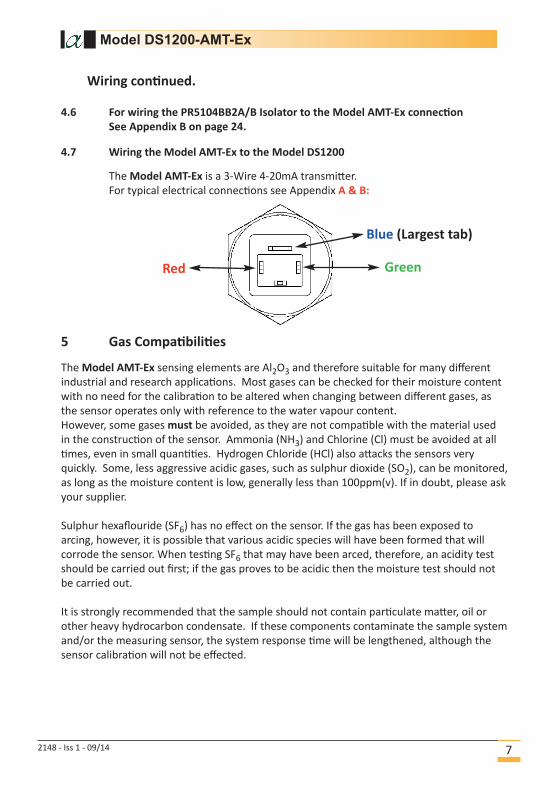
4.7 Wiring the Model AMT-Ex to the Model DS1200
The Model AMT-Ex is a 3-Wire 4-20mA transmitter.
For typical electrical connections see Appendix A & B:
5 Gas Compatibilities
The Model AMT-Ex sensing elements are Al2O3 and therefore suitable for many different
industrial and research applications. Most gases can be checked for their moisture content
with no need for the calibration to be altered when changing between different gases, as
the sensor operates only with reference to the water vapour content.
However, some gases must be avoided, as they are not compatible with the material used
in the construction of the sensor. Ammonia (NH3) and Chlorine (Cl) must be avoided at all
times, even in small quantities. Hydrogen Chloride (HCl) also attacks the sensors very
quickly. Some, less aggressive acidic gases, such as sulphur dioxide (SO2), can be monitored,
as long as the moisture content is low, generally less than 100ppm(v). If in doubt, please ask
your supplier.
Sulphur hexaflouride (SF6) has no effect on the sensor. If the gas has been exposed to
arcing, however, it is possible that various acidic species will have been formed that will
corrode the sensor. When testing SF6 that may have been arced, therefore, an acidity test
should be carried out first; if the gas proves to be acidic then the moisture test should not
be carried out.
It is strongly recommended that the sample should not contain particulate matter, oil or
other heavy hydrocarbon condensate. If these components contaminate the sample system
and/or the measuring sensor, the system response time will be lengthened, although the
sensor calibration will not be effected.
Blue (Largest tab)
Red Green
6 Installing the Model AMT-Ex in an air/gas sampling system
The piping installation schematic diagram (see page 9) shows all components that
could be used in a dry gas measurement application. Not all the items shown will be
required for every installation.
Care should be taken to ensure that the sample presented to the measuring sensor is
not contaminated with any component that will damage, contaminate or affect the
sensor in a way that will impair the system accuracy.
It is strongly recommended that the sample should not contain particulate matter, oil
or other heavy hydrocarbon condensate. If these components contaminate the sample
system and/or the measuring sensor, the system response time will be lengthened,
although the sensor calibration will not be effected.
The sample must not contain ammonia, chlorine, ozone or any wet acid vapours or
liquids as these will permanently damage the sensor and impair calibration accuracy.
The flow rate, although not critical to the sensor measurement, should be low enough
to avoid abrasion to the sensor surface without being so low as to extend the system
response time to an unacceptable level. In general, a flow rate of between 2 and 3
litres/min at NTP will give the right balance.
The sensor is a variable capacitor, which is directly affected by changes in partial
pressure of water vapour. These changes that are proportional to the dew/frost
point temperature are displayed on the instrument indicator.
The measuring sensor can be installed directly into the process line, but this does create
problems with access for maintenance and calibration. It is for these reasons that we
recommend that the sensor be installed in a bypass, fast loop or total loss sample system
where the sensor is accessible without interrupting the main process flow line.
Model DS1200-AMT-Ex
2148 - Iss 1 - 09/148
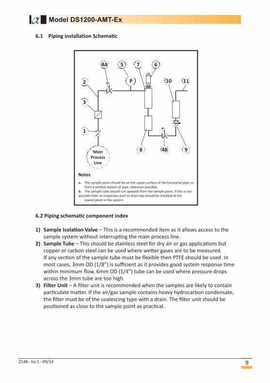
6.1 Piping installation Schematic
Model DS1200-AMT-Ex
6.2 Piping schematic component index
1) Sample Isolation Valve – This is a recommended item as it allows access to the
sample system without interrupting the main process line.
2) Sample Tube – This should be stainless steel for dry air or gas applications but
copper or carbon steel can be used where wetter gases are to be measured.
If any section of the sample tube must be flexible then PTFE should be used. In
most cases, 3mm OD (1/8”) is sufficient as it provides good system response time
within minimum flow. 6mm OD (1/4”) tube can be used where pressure drops
across the 3mm tube are too high.
3) Filter Unit – A filter unit is recommended when the samples are likely to contain
particulate matter. If the air/gas sample contains heavy hydrocarbon condensate,
the filter must be of the coalescing type with a drain. The filter unit should be
positioned as close to the sample point as practical.
Main
Process
Line
4B 9
11102
3
1
4A 5
P
7 6
8
a. The sample point should be on the upper surface of the horizontal pipe, or
from a vertical section of pipe, wherever possible.
b. The sample tube should run upwards from the sample point. If this is not
possible then an inspection port or drain tap should be installed at the
lowest point in the system.
Notes
2148 - Iss 1 - 09/14 9
Model DS1200-AMT-Ex
6.2 Piping schematic component index continued.
4) Pressure Reduction Valve or Pressure Regulator – If the sample is to be measured
at atmospheric pressure then the valve 4A should be fitted and 4B omitted from
the system. If the sample is to be measured at full line pressure and the exhaust
vented to atmosphere, then valve 4B should be fitted and 4A omitted from the
system.
If measurements are to be taken at full line pressure and the sample is to be
returned to a part of the main line or a vent, which is at a pressure higher than
atmospheric, and the input to that line needs a controlled pressure, then both 4A
and 4B will be required.
5) Sample Pressure Gauge – This is not a critical part of the moisture measurement
but may be required if Dew/Frost point measurements are to be made at higher
than atmospheric pressure.
6) Measuring Sensor.
7) Sensor Holder.
8) Desiccant Chamber – This item is required when the sampling is to be intermittent.
When installed, it prevents the ingress of wet air to the sample system while the
sample is not flowing, improving the response time.
9) Flow Control Valve – This can be a separate item or combined with the flow
indicator.
10)Flow Indicator – The recommended sample flow is 2 to 3 litres/min at NTP.
11)Sample Exhaust – The exhaust can be vented to atmosphere or returned to the
process line as discussed above.
7 Installing and Commissioning the Model AMT-Ex
It is advisable to carry out an initial purge routine of the sample loop, before installing
the transmitter, in order to remove the possibility of sensor damage on start-up.
Refer to the sample system schematic on page 9. Open the inlet isolation valve slowly,
until a small flow of air/gas at atmospheric pressure flows through the inlet pipe work
to the transmitter holder and exhausts through the sensor entry port of the transmit-
ter holder.
Allow this purge to continue for about 15 to 20 minutes to remove any residual mois-
ture from the sample pipe work and components.
Close the inlet isolation valve and install the transmitter into the transmitter holder.
Locate and secure the four-pin transmitter cable connector in positioned on the
transmitter. Use the locking screw in order to affect a weatherproof seal.
NOTE: - The Plug and socket will only locate in one position, as the GND (ground) pin
is different to the other three pins.
2148 - Iss 1 - 09/1410
Model DS1200-AMT-Ex
Open the inlet valve slowly, again and, by opening all valves after the transmitter holder,allow a low-pressure purge through the whole sample system. (Note. If a closed by-passloop is installed, this section of the procedure is not possible).
Set the required pressures and flows within the sample loop.
This completes the installation and commissioning but, on initial start-up, it could takeseveral hours for the system to reach equilibrium.
WARNING: Leaving the transmitter installed in plant that will be unused for long periods of time will inevitably cause damage to the sensing element, due to condensation or air-bound contamination, rendering it inaccurate or unusable. It is, therefore, critically important to note that, if procedure in section 6 is being carried out as part of initial tests and/or plant acceptance trials, prior to shipping and storage, the transmitter should be removed from the system, following completion of the tests/trials and stored in its original packaging, ensuring that the desiccant capsule is in place, up to the time of final plant commissioning.
It is further recommended that, if the transmitter is to be stored for periodof 12 months or more, a factory calibration verification be carried out, to ensure that any transit or storage damage that may have occurred, is identified and corrected, prior to final installation and commissioning.
7.1 Operation
• The system is designed to operate continuously, with a minimum amount of
operator input.
• It is, however, advisable to inspect the sample loop periodically to ensure
that the required pressures and flows are being maintained.
• The number and type of items employed in the sample loop will determine
what, if any, other routine checks should be made. If, for instance, a filter is
used, the filter element should be inspected periodically and changed when
necessary.
• The instrument should not require any routine maintenance but if any mal
function is suspected it is advisable to contact your local dealer.
• Should it be necessary, at any time or for whatever reason, to change either
the instrument or sensor, it should be noted that the components of the
Model DS1200-AMT-Ex system are fully and completely interchangeable provided
that the corresponding instrument/sensor range is requested. The only adjustment
necessary would be the alarm set points in the case of the instrument.
• While the sensor should give several years operation, it is advisable to confirm
the calibration, from time to time, to ensure accurate operation of the system.
2148 - Iss 1 - 09/14 11
7 Installing and Commissioning the Model AMT-Ex continued.
Model DS1200-AMT-Ex
7 Installing and Commissioning the Model AMT-Ex continued.
7.2 Commissioning
• Switch the instrument power ON. The display will read “SE.BR“. This is the 'Sensor
Wire Break' display condition.
7.3 Setting the Alarm Trip Points
• To activate the quick alarm settings screen press either the ”▲” or ”▼” buttons,
while the Model DS1200 is displaying the moisture level. The DS1200 will flash the
“F.SET” message followed by a selection menu for Alarm 1 or 2 relay. Scroll to the
required alarm and press the “OK” button. The DS1200 then displays the message
“SETP” momentarily before displaying the current set point in % of scale.
See next page for procedure:
2148 - Iss 1 - 09/1412
Select Alarm Channel
“REL 1”
“REL 2”
using ▲and ▼
Set Alarm
Activation Point
using ▲ and ▼as % of scale
Settings:
▲ Increase set point
▼ Decrease set point
OK Save & exit the menu
OK
Note: - that on some Models, the Hysteresis is also settable.
2148 - Iss 1 - 09/14 13
Model DS1200-AMT-Ex
7.3 Setting the Alarm Trip Points continued.
Model DS1200-AMT-Ex
8 Normal Operation
8.1 Analogue 4-20mA Mode (3-wire)
In normal operation, the transmitter will produce a 4-20mA signal, which is
proportional to the level of moisture in the gas being monitored. The moisture
reading is sampled and up dated once per second. The Model AMT-Ex has 3020
distinct steps over the 4 to 20mA range corresponding to a resolution of 0.005mA.
8.2 Autocal
Warning Do Not power down during the AutoCal process as this
can lead to corruption of the AMTs memory.
AutoCal allows the user to ensure accuracy to the laboratory calibration by checking
the span of the transmitter and correcting for any deviation. It should be operated
periodically, every 2 to 3 months or when verification of the Model AMT-Ex is
required.
The Model AMT-Ex is supplied with an electronic autocal, which allows the calibration
span of the transmitter to be adjusted. The autocal is controlled by the 2 buttons
located on the side of the Model AMT –Ex labelled ‘W’ (wet) and ‘D’ (dry).
Note : - The Model AMT-Ex must be connected to an indicator or some device able to
supply an accurate measurement of the mA output.
8.3 Pre-conditioning the transmitter
To perform the autocal, the transmitter needs to be removed from the process gas at
which point the display/indicator will read the ambient dewpoint or full scale (if the
ambient dewpoint level is above the range of the AMT-Ex). Expose the transmitter to
the known autocal moisture level and allow the transmitter to attain equilibrium. (For
technical questions and advice on the time taken to attain equilibrium Contact your
Model AMT-Ex supplier). See next steps on page 15.
Model DS1200-AMT-Ex
2148 - Iss 1 - 09/1414
Model DS1200-AMT-Ex
8.3 Pre-conditioning the transmitter continued.
Method 1: -
Expose to a known moisture level. (Applicable to all versions of Model AMT-Ex
Transmitters)
If a known gas is available within the range of the transmitter, then the Model AMT-Ex
can be AutoCaled against this value.
Method 2: -
Saturating method. (Only applicable to 0°C (32°F) and –20°C (-4°F) top end range
Model AMT-Ex transmitters)
When the Model AMT-Ex sensing element is exposed to a dewpoint level above the top
end range of the transmitter, the sensor will saturate and the transmitter can be Auto-
Caled to 0°C or –20°C. For both 0°C and –20°C Model AMT-Ex’s, ambient dewpoint is
usually adequate to saturate the sensor.
Method 3: -
Set against Ambient moisture level. (Only applicable to 20°C (68°F) top end range
Model AMT-Ex transmitters)
When the ambient dewpoint is known, then the Model AMT-Ex’s can be AutoCaled to
the ambient value.
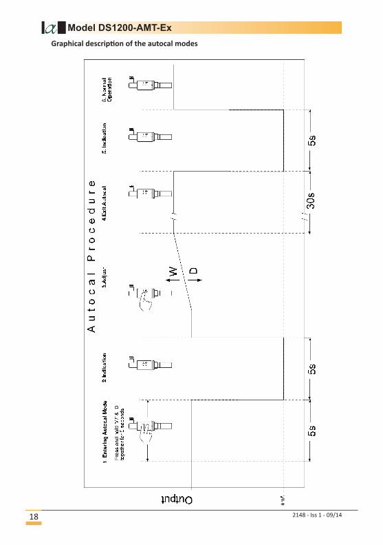
8.4 Entering Autocal Mode
Once the transmitter has been pre-conditioned, the AutoCal Mode of the Model AMT-
Ex can be activated. Press and hold the ‘W’ and ‘D’ buttons, simultaneously for 5 sec-
onds. ONLY PRESS THE BUTTONS IF THE SENSOR IS PROPERLY PRE-CONDITIONED.
FAILURE TO COMPLY WILL CORRUPT THE TRANSMITTERS CALIBRATION.
The attached 4-20mA display will (after the 5 seconds) indicate the bottom range of
the Model AMT-Ex (or 4mA if reading current) for 5 seconds, confirming that autocal
mode has been entered. The buttons should be released once the display indicates the
bottom range.
After the 5 seconds delay the Model AMT-Ex will revert to the measured dewpoint and
the buttons will be active.
8.5 Adjust the autocal
Use the ‘W’ and ‘D’ buttons to move the reading up or down so that the desired
dewpoint is displayed.
2148 - Iss 1 - 09/14 15
Model DS1200-AMT-Ex
8.5 Adjust the autocal continued.
Method 1: - Adjust the Model AMT-Ex reading until the indicator reads the known
moisture level.
Method 2: - Adjust the Model AMT-Ex reading until the indicator reads 0°C or
–20°C whichever is applicable to the Model AMT-Ex being AutoCaled
Method 3: - Adjust the Model AMT-Ex reading until the indicator reads the known
ambient moisture reading.
8.6 Completing the autocal
Once the desired value is reached, the autocal process can be completed simply by
leaving the buttons untouched for 30 seconds. After the 30 seconds, the display will
indicate the bottom of the range for a period of 5 seconds and then the Model AMT-Ex
will exit the autocal mode.
The Model AMT-Ex will now output the corrected dewpoint and can be reinserted into
the process.
A graphical description of the autocal modes is given on page 18.
8.7 Model AMT-Ex Range AutoCal Method Lookup Table
Use the table below to decide which AutoCal methods are appropriate for your
ModelAMT-Ex.
Range Methods Appropriate
-80 to –20°C -112°F to –4°F 1 & 2
-110 to –20°C -166°F to –4°F 1 & 2
-120 to –20°C -184°F to –4°F 1 & 2
-65 to 0°C -85°F to 32°F 1 & 2
-80 to 0°C -112°F to 32°F 1 & 2
-100 to 0°C -148°F to 32°F 1 & 2
-65 to 20°C -85°F to 68°F 1 & 3
-100 to 20°C -148°F to 68°F 1 & 3
-120 to 20°C -184°F to 68°F 1 & 3
1-1000ppm(v) 0.1-100ppm(v) 0.01-10ppm(v) 1
1-1000ppb(v) 1
0.01-10g/m3 0.001to1g/m3 1
0.1-10lb/MMSCF 0.1-25lb/MMSCF 0.1-50lb/MMSCF 1
2148 - Iss 1 - 09/1416
Model DS1200-AMT-Ex
8.8 Faults/Errors
If the sensor is short-circuited, the transmitter will produce a constant 20.75mA
output.
If the sensor is open-circuited, the transmitter will produce a constant 20.50mA
output.
If the hardware develops a fault, the transmitter will produce 21.0mA for 5 seconds
after switch on and then continue to give an output.
2148 - Iss 1 - 09/14 17
Model DS1200-AMT-Ex
2148 - Iss 1 - 09/1418
Graphical description of the autocal modes
Model DS1200-AMT-Ex
9 Specifications
9.1 Model DS1200 Specifications:
• Temperature operating range = -20°C to +60°C
• Power supply = 20 – 300 VDC, or 22 to 253 VAC 50 – 60 Hz
• 3.2W internal power consumption
• 3.5W maximum power consumption
• Isolation voltage test / operation = 2.3KVAC / 250 VAC
• Signal to noise ratio = Min 60dB (0-100kHz)
• Display Response time (0-90%, 100 to 10%) = 0.4s.
• Wire size, pin 45 & 46 (max) = 1 x 1.5mm2 stranded wire
• Wire size, others (max) = 1 x 2.5mm2 stranded wire
• Relative Humidity = < 95% RH
• Dimensions (HxWxD) = 48 x 96 x 120mm
• Cut out dimensions = 44.5 x 91.5mm
• Ingress Protection = (Front panel) IP65
• Weight = 230g
• Input
o From Model AMT-Ex
o Error detection = Cable loop break
• Display
o Display Readout = AMT range
o Scrolled error display
• Current Output
o Programmable signal ranges = 0…20 or 4…20mADC (Factory set)
o Load (max) 20mA / 800Ω / 16VDC
o Load stability ≤ 0.01 % of span / 100 Ω
• Relay
o Relay function = setpoint
o Hysterisis 1% of range
o Max voltage = 250 VRMS
o Max Current = 2A /AC
o Max AC power = 500VA
o Max current at 24 VDC = 1A
9.2 Model AMT-Ex Specification
Output Signal : 4 to 20mA Linear
Operating Voltage : 18V - 28V DC. Reverse polarity
protected.
Maximum Series Resistance : = {40 x (Supply Voltage – 7)}Ω
Sensing element : Ultra High Capacitance - Aluminium
Oxide Type
AutoCal : Field calibration / Span check facility.
Factory calibration : Supplied with Certificate of Calibration
traceable to NPL / NIST
Accuracy : ± 2°C dewpoint (NPL / NIST traceable
for range -90°C to 20°C)
2148 - Iss 1 - 09/14 19
Model DS1200-AMT-Ex
9.2 Model AMT-Ex Specification continued.
Temperature compensation : Temperature compensated for
operating range.
Resolution : 5 µA
Repeatability : Better than ±0.3°C dewpoint
Operating temperature : -20°C to +60°C
Storage Temperature : -20°C to +70°C
Operating Pressure : From 1kPa (0.01 barA) to Maximum
35,000kPa ( 350 barA)
Operating Humidity (External) : Maximum - 95% RH Non-condensing
Sample Flow Rate : Independent but ideally 2 to 5 litres per
minute. Max: 25 litres/min.
Cable Terminations : IP66 (NEMA4X) rated, size C, DIN EN
175301 connector at the transmitter
and other end terminated with
bootlace ferrules.
Cable : Supplied with 2m standard cable.
Nominal diameter 3.4mm, 92ohms/km.
Electromagnetic Compatibility (EMC): Immunity: Complies with EN 61000-6-
1:2001
Emissions : Complies with EN 61000-6-3:2000
Warm Up Time : 10 seconds
Fault Conditions Sensor Open Circuit : Output drives to 20.50mA
Sensor Short Circuit : Output drives to 20.75mA
System Error : Output drives to 21.00mA
Isolation : Sensing Element connected to the
4-20mA loop but isolated from body.
Transmitter Enclosure : 316 Stainless steel body with size C,
DIN EN 175301 connector.
Sensor Protection : 316 Sintered stainless steel filter -
50 micron
Probe Material (Wetted Parts) : 316 Stainless Steel
Weatherproof Classification : IP66 / NEMA4X when Connector mated
to Transmitter.
Mechanical Connection : 3/4” UNF (16tpi) with integral Viton
“O” ring seal.
Mechanical Warranty : 24 months in case of faulty workman
ship and defective parts.
Calibration Warranty : 12 months subject to usage.
Weight : 175grams (includes connector)
Protection : ATEX
2148 - Iss 1 - 09/1420
Model DS1200-AMT-Ex
9.3 Signal Isolator Specifications (1 and 2 Channels)
Part Number : PR5104BB2A/B
Supply voltage, universal : 21.6...253 VAC, 50...60 Hz or
19.2...300 VDC
Mechanical specifications
Dimensions (HxWxD) : 109 x 23.5 x 130 mm
DIN rail type : DIN 46277
Approvals
EMC : EN 61326-1
LVD : EN 61010-1
PELV/SELV : IEC 364-4-41 and EN 60742
ATEX : DEMKO 99ATEX126013
UL : UL 913, UL 508
GOST R : Yes
GOST Ex : Yes
DNV Marine : Stand. f. Certific. No. 2.4
9.4 Applicable Standards
• EMC 2004/108/EC
o Emissions and immunity = EN 61326
• LVD 73/23/EEC
o Low voltage = EN 61010-1
• UL
o Standard for Safety = UL 508
9.5 Model AMT-Ex Transmitter Intrinsic Safety Certification Standards:
EN 60079-0:2009 EN 60079-11:2012 EN 61241-11:2012
Ex II 1GD Ex ia IIC T4 Ex iaD 20 T1350C (-200C ≤ Ta ≤ +600C)
2148 - Iss 1 - 09/14 21
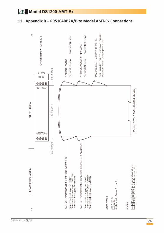
11 Appendix B – PR5104BB2A/B to Model AMT-Ex Connections
Model DS1200-AMT-Ex
2148 - Iss 1 - 09/14 24
Model DS1200-AMT-Ex
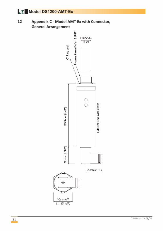
12 Appendix C - Model AMT-Ex with Connector,
General Arrangement
2148 - Iss 1 - 09/1425
Model DS1200-AMT-Ex
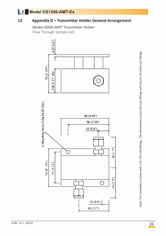
13 Appendix D – Transmitter Holder General Arrangement
2148 - Iss 1 - 09/14 26
Model ADSH-AMT Transmitter Holder
Flow Through Sample Cell
No
te:
Th
e A
sse
mb
ly is
sh
ow
n w
ith
1/4
”O
D t
ub
e fi
ttin
gs.
Th
e d
ime
nsi
on
s a
cro
ss t
he
tu
be
fitti
ng
s w
ill v
ary
fo
r a
ll o
the
r si
ze fi
ttin
gs.

14 Contact Information
Head Office:
Alpha Moisture Systems
96 City Road
Bradford
West Yorkshire
BD8 8ES
United Kingdom
Tel: +44 (0) 1274 733100
Fax: +44 (0) 1274 733200
Email: [email protected]
Web: www.dew-point.com
Office Opening Hours:
Monday - Thursday
8.30am - 5.30pm GMT
Friday
8.30am - 5.00pm GMT
Notes:
Model DS1200-AMT-Ex
Location
2148 - Iss 1 - 09/1427