Embed Size (px)
Citation preview

2ch
• LA-21004ch
• LA-4100 • LA-42005ch
• LA-51000
Amplifiers
PROTECTPOWERBASS
BOOST
HIGH LEVELINPUT
LINEOUTPUT
LINEINPUT
LOWPASS
HIGHPASS
X-OVER
HP LP
FULL
4V 0.2V 60Hz 1.2kHz 40Hz 150Hz 0dB 12dBR
R
L
L
LEVELINPUT
FUSE
GND REM +12V
POWER INPUT
L
SPEAKER OUTPUT
BRIDGED
R
HIGH LEVEL INPUT
CH3
CH3
CH4
CH4
CH2
CH2
CH1
4CH 2CH
CH1
LINEOUTPUT
X-OVER
X-OVER
INPUT MODELEVEL BASS BOOST HIGH PASS LOW PASS
CH
1/C
H2
CH
3/C
H4
LIN
E IN
PU
T
HPLPFULL
HPLPFULL
4V 0dB 12dB 60Hz 1.2kHz 30Hz 250Hz0.2V
4V 0dB 12dB 60Hz 1.2kHz 30Hz 250Hz0.2V
R
L
FUSE
GND REMPOWER
PROTECT
+12V
POWER INPUT
CH1
SPEAKER OUTPUTBRIDGED BRIDGED
CH2CH3CH4
CH2CH4
OFF ON
LP/BP FULL
BPF
BPF
HP
X-OVER INPUT MODE
TWIN SUB
LP/BP FULLHP
X-OVERBASS REMOTE
LOWPASS
HIGHPASS
BASSBOOST
CH
1/C
H2
CH
3/C
H4 CH3
CH4 CH2
CH1
LINE INPUTLINE OUTPUT
PROTECT POWER
0dB 12dB 10Hz 1.2kHz30Hz 150Hz
LEVEL
4V 0.2V
0dB 12dB 10Hz 1.2kHz30Hz 150Hz4V 0.2V
R
L
FUSE
GND REM +12V
POWER INPUT
CH1
SPEAKER OUTPUTBRIDGED BRIDGED
CH2 CH3 CH4
FULL HPF FULL HPF
CH1
CH2
CH 3/4 CH 1/2
CH3
CH4
CH4 CH5
CH5
CH5
LIN
E IN
PU
T
PROTECT
POWER
LEVEL
LEVEL
LEVEL
MODEX-OVERX-OVER
HPF
CH 5 CH 5
HPF
REMOTE
LPFBASS EQSUBSONIC0dB 12dB
10Hz
15Hz 55Hz 30Hz 150Hz
150Hz 10Hz 150Hz5V
5V
0.2V 5V 0.2V
0.2V
FUS
E
GNDREM+12V
POWER INPUT
CH1
SPEAKER OUTPUTBRIDGED BRIDGED
CH2 CH3 CH4 CH5
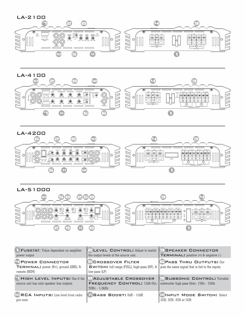
Fuse(s): Value dependant on amplifier
power output
Level Control: Adjust to match
the output levels of the source unit.
Speaker Connector Terminal: positive (+) & negative (-)
Power Connector Terminal: power (B+), ground (GND), &
remote (REM)
Crossover Filter Switch: full range (FULL), high-pass (HP), &
low-pass (LP)
Pass Thru Outputs: Out-
puts the same signal that is fed to the inputs.
High Level Inputs: Use if the
source unit has only speaker line outputs.
Adjustable Crossover Frequency Control: 12db/Oct;
30Hz - 1.2kHz
Subsonic Control: Variable
subwoofer high pass filter; 15Hz - 55Hz
RCA Inputs: Line level from radio
pre-outs.
Bass Boost: 0dB - 12dB Input Mode Switch: Select
2CH, 3CH, 4CH or 5CH
LA-2100
LA-4100
LA-4200
LA-51000
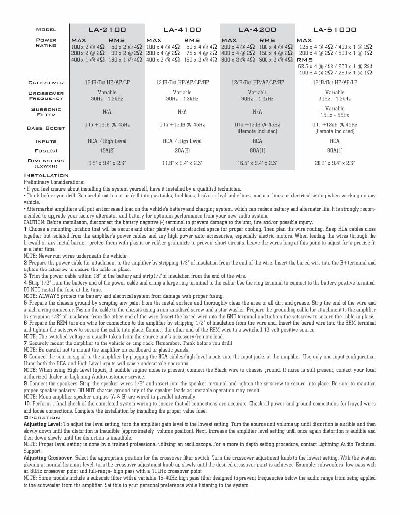
Model LA-2100 LA-4100 LA-4200 LA-51000Power Rating
MAX100 x 2 @ 4Ω200 x 2 @ 2Ω400 x 1 @ 4Ω
RMS50 x 2 @ 4Ω90 x 2 @ 2Ω
180 x 1 @ 4Ω
MAX100 x 4 @ 4Ω200 x 4 @ 2Ω400 x 2 @ 4Ω
RMS50 x 4 @ 4Ω75 x 4 @ 2Ω
150 x 2 @ 4Ω
MAX200 x 4 @ 4Ω400 x 4 @ 2Ω800 x 2 @ 4Ω
RMS100 x 4 @ 4Ω150 x 4 @ 2Ω300 x 2 @ 4Ω
MAX125 x 4 @ 4Ω / 400 x 1 @ 2Ω200 x 4 @ 2Ω / 500 x 1 @ 1Ω
RMS62.5 x 4 @ 4Ω / 200 x 1 @ 2Ω100 x 4 @ 2Ω / 250 x 1 @ 1Ω
Crossover 12dB/Oct HP/AP/LP 12dB/Oct HP/AP/LP/BP 12dB/Oct HP/AP/LP/BP 12dB/Oct HP/AP/LP
Crossover Frequency
Variable 30Hz - 1.2kHz
Variable 30Hz - 1.2kHz
Variable 30Hz - 1.2kHz
Variable 30Hz - 1.2kHz
Subsonic Filter N/A N/A N/A
Variable 15Hz - 55Hz
Bass Boost0 to +12dB @ 45Hz 0 to +12dB @ 45Hz 0 to +12dB @ 45Hz
(Remote Included)0 to +12dB @ 45Hz (Remote Included)
Inputs RCA / High Level RCA / High Level RCA RCA
Fuse(s) 15A(2) 20A(2) 80A(1) 80A(1)
Dimensions (LxWxH) 9.5” x 9.4” x 2.3” 11.8” x 9.4” x 2.3” 16.5” x 9.4” x 2.3” 20.3” x 9.4” x 2.3”
InstallationPreliminary Considerations: • If you feel unsure about installing this system yourself, have it installed by a qualified technician. • Think before you drill! Be careful not to cut or drill into gas tanks, fuel lines, brake or hydraulic lines, vacuum lines or electrical wiring when working on any vehicle. • Aftermarket amplifiers will put an increased load on the vehicle’s battery and charging system, which can reduce battery and alternator life. It is strongly recom-mended to upgrade your factory alternator and battery for optimum performance from your new audio system.CAUTION: Before installation, disconnect the battery negative (-) terminal to prevent damage to the unit, fire and/or possible injury.1. Choose a mounting location that will be secure and offer plenty of unobstructed space for proper cooling. Then plan the wire routing. Keep RCA cables close together but isolated from the amplifier’s power cables and any high power auto accessories, especially electric motors. When feeding the wires through the firewall or any metal barrier, protect them with plastic or rubber grommets to prevent short circuits. Leave the wires long at this point to adjust for a precise fit at a later time. NOTE: Never run wires underneath the vehicle.2. Prepare the power cable for attachment to the amplifier by stripping 1/2” of insulation from the end of the wire. Insert the bared wire into the B+ terminal and tighten the setscrew to secure the cable in place. 3. Trim the power cable within 18” of the battery and strip1/2”of insulation from the end of the wire. 4. Strip 1/2” from the battery end of the power cable and crimp a large ring terminal to the cable. Use the ring terminal to connect to the battery positive terminal. DO NOT install the fuse at this time. NOTE: ALWAYS protect the battery and electrical system from damage with proper fusing.5. Prepare the chassis ground by scraping any paint from the metal surface and thoroughly clean the area of all dirt and grease. Strip the end of the wire and attach a ring connector. Fasten the cable to the chassis using a non-anodized screw and a star washer. Prepare the grounding cable for attachment to the amplifier by stripping 1/2” of insulation from the other end of the wire. Insert the bared wire into the GND terminal and tighten the setscrew to secure the cable in place.6. Prepare the REM turn-on wire for connection to the amplifier by stripping 1/2” of insulation from the wire end. Insert the bared wire into the REM terminal and tighten the setscrew to secure the cable into place. Connect the other end of the REM wire to a switched 12-volt positive source. NOTE: The switched voltage is usually taken from the source unit’s accessory/remote lead.7. Securely mount the amplifier to the vehicle or amp rack. Remember: Think before you drill! NOTE: Be careful not to mount the amplifier on cardboard or plastic panels.8. Connect the source signal to the amplifier by plugging the RCA cables/high level inputs into the input jacks at the amplifier. Use only one input configuration. Using both the RCA and High Level inputs will cause undesirable operation.NOTE: When using High Level Inputs, if audible engine noise is present, connect the Black wire to chassis ground. If noise is still present, contact your local authorized dealer or Lightning Audio customer service.9. Connect the speakers. Strip the speaker wires 1/2” and insert into the speaker terminal and tighten the setscrew to secure into place. Be sure to maintain proper speaker polarity. DO NOT chassis ground any of the speaker leads as unstable operation may result. NOTE: Mono amplifier speaker outputs (A & B) are wired in parallel internally.10. Perform a final check of the completed system wiring to ensure that all connections are accurate. Check all power and ground connections for frayed wires and loose connections. Complete the installation by installing the proper value fuse.OperationAdjusting Level: To adjust the level setting, turn the amplifier gain level to the lowest setting. Turn the source unit volume up until distortion is audible and then slowly down until the distortion is inaudible (approximately ¾ volume position). Next, increase the amplifier level setting until once again distortion is audible and then down slowly until the distortion is inaudible. NOTE: Proper level setting is done by a trained professional utilizing an oscilloscope. For a more in depth setting procedure, contact Lightning Audio Technical Support.Adjusting Crossover: Select the appropriate position for the crossover filter switch. Turn the crossover adjustment knob to the lowest setting. With the system playing at normal listening level, turn the crossover adjustment knob up slowly until the desired crossover point is achieved. Example: subwoofers- low pass with an 80Hz crossover point and full-range- high pass with a 100Hz crossover pointNOTE: Some models include a subsonic filter with a variable 15-40Hz high pass filter designed to prevent frequencies below the audio range from being applied to the subwoofer from the amplifier. Set this to your personal preference while listening to the system.
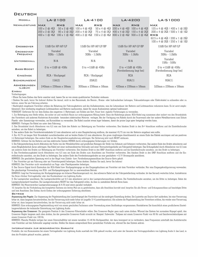
Modell LA-2100 LA-4100 LA-4200 LA-51000Nennleistung MAX
100 x 2 @ 4Ω200 x 2 @ 2Ω400 x 1 @ 4Ω
RMS50 x 2 @ 4Ω90 x 2 @ 2Ω
180 x 1 @ 4Ω
MAX100 x 4 @ 4Ω200 x 4 @ 2Ω400 x 2 @ 4Ω
RMS50 x 4 @ 4Ω75 x 4 @ 2Ω
150 x 2 @ 4Ω
MAX200 x 4 @ 4Ω400 x 4 @ 2Ω800 x 2 @ 4Ω
RMS100 x 4 @ 4Ω150 x 4 @ 2Ω300 x 2 @ 4Ω
MAX125 x 4 @ 4Ω / 400 x 1 @ 2Ω200 x 4 @ 2Ω / 500 x 1 @ 1Ω
RMS62.5 x 4 @ 4Ω / 200 x 1 @ 2Ω100 x 4 @ 2Ω / 250 x 1 @ 1Ω
Crossover 12dB/Oct HP/AP/LP 12dB/Oct HP/AP/LP/BP 12dB/Oct HP/AP/LP/BP 12dB/Oct HP/AP/LP
Crossover- Frequenz
Variabel 30Hz - 1.2kHz
Variabel 30Hz - 1.2kHz
Variabel 30Hz - 1.2kHz
Variabel 30Hz - 1.2kHz
Unterschall N/A N/A N/AVariabel
15Hz - 55Hz
Bass-Boost0 to +12dB @ 45Hz 0 to +12dB @ 45Hz 0 to +12dB @ 45Hz
(Fernbedienung liegt bei)0 to +12dB @ 45Hz
(Fernbedienung liegt bei)
Eingänge RCA / Hochpegel RCA / Hochpegel RCA RCA
Sicherung(en) 15A(2) 20A(2) 80A(1) 80A(1)
Abmessungen (LxBxH) 240mm x 238mm x 58mm 300mm x 238mm x 58mm 420mm x 238mm x 58mm 520mm x 238mm x 58mm
Deutsch
EinbauVorüberlegungen: • Wenn Sie beim Einbau des Geräts unsicher sind, lassen Sie es von einem qualifizierten Techniker einbauen. • Denken Sie nach, bevor Sie bohren! Achten Sie darauf, nicht in den Benzintank, die Benzin-, Brems- oder hydraulischen Leitungen, Vakuumleitungen oder Elektrokabel zu schneiden oder zu bohren, wenn Sie am Fahrzeug arbeiten. • Nachträglich eingebaute Verstärker erhöhen die Belastung der Fahrzeugbatterie und des Aufladesystems, was die Lebensdauer der Batterie und Lichtmaschine reduzieren kann. Es ist äußerst empfe-hlenswert, Ihre werkseitig eingebaute Lichtmaschine und Batterie nachzurüsten, damit Ihr neues Audiosystem optimal funktioniert.VORSICHT: Entfernen Sie vor dem Einbau den negativen (-) Batteriepol, um Schäden am Gerät, Feuer bzw. mögliche Verletzungen zu vermeiden.1. Zur Befestigung eine Stelle wählen, die sicher ist und reichlich Raum zur ordnungsgemäßen Kühlung bietet. Dann die Kabelwege planen. RCA-Kabel eng zusammen aber isoliert von den Stromkabeln des Verstärkers und anderem Hochstrom-Autozubehör – besonders elektrischen Motoren – verlegen. Bei der Verlegung von Kabeln durch die Feuerwand oder über andere Metallbarrieren zum Schutz Plastik- oder Gummiringe verwenden, um Kurzschlüsse zu vermeiden. Die Kabel zunächst etwas länger belassen, damit die präzise Länge später festgelegt werden kann. HINWEIS: Verlegen Sie Kabel nie unter dem Fahrzeug.2. Das Stromkabel durch Abisolieren von 6,5 mm am Ende des Kabels zur Befestigung am Verstärker vorbereiten. Den blanken Draht in den „B+“-Anschluss einführen und die Einstellschraube anziehen, um das Kabel zu befestigen. 3. Das andere Ende des Verstärkerstromkabels 6,5 mm abisolieren und in eine Hauptsicherung einführen, die maximal 45,75 cm von der Batterie eingebaut sein sollte. 4. Ein 45,75 cm langes Stück Stromkabel zurechtschneiden und an beiden Enden 6,5 mm abisolieren. Ein großes ringförmiges Anschlussstück an einem Ende des Kabels ancrimpen und am positiven (+) Batteriepol befestigen. Das andere Ende an der Hauptsicherungshalterung anbringen. Die Sicherung jetzt noch NICHT einbauen. HINWEIS: Schützen Sie die Batterie und das elektrische System IMMER durch ordnungsgemäße Sicherungen vor Schäden.5. Die Fahrgestellerdung durch Abkratzen der Farbe von der Metalloberfläche und gründliches Reinigen der Stelle von Schmutz und Schmiere vorbereiten. Das andere Ende des Drahts abisolieren und einen Ringkabelschuh daran anbringen. Das Kabel mit einer nichtanodisierten Schraube und einer Sternunterlegscheibe am Fahrgestell befestigen. Das Erdungskabel durch Abisolieren von 6,5 mm am anderen Ende des Drahts zur Befestigung am Verstärker vorbereiten. Den blanken Draht in den „GND“-Anschluss einführen und die Einstellschraube anziehen, um den Draht zu befestigen.6. Das Fernbedienungskabel durch Abisolieren von 6,5 mm am Ende des Drahts zum Anschließen am Verstärker vorbereiten. Den blanken Draht in den „GND“-Anschluss einführen und die Ein-stellschraube anziehen, um den Draht zu befestigen. Das andere Ende des Fernbedienungsdrahts an eine geschaltete +12 V-Stromquelle anschließen. HINWEIS: Die geschaltete Spannung wird in der Regel vom Zubehör- bzw. Fernbedienungsanschluss des Source-Geräts geholt.7. Den Verstärker gut am Fahrzeug oder am Verstärkergestell befestigen. Daran denken: Denken Sie nach, bevor Sie bohren! HINWEIS: Den Verstärker nicht versehentlich an Papp- oder Plastikpaneelen befestigen.8. Das Source-Signal durch Einstecken der RCA-Kabel bzw. Hochpegeleingänge an den Eingangsbuchsen am Verstärker mit dem Verstärker verbinden. Nur eine Eingangskonfigurierung verwenden. Die gleichzeitige Verwendung von RCA- und Hochpegeleingängen führt zu unerwünschtem Betrieb. HINWEIS: Liegt bei Verwendung der Hochpegeleingänge ein hörbares Maschinengeräusch vor, das schwarze Kabel mit der Fahrgestellerdung verbinden. Ist das Geräusch weiterhin hörbar, kontaktieren Sie Ihren örtlichen Vertragshändler oder den Kundendienst von Lightning Audio. 9. Die Lautsprecher anschließen. Die Lautsprecherdrähte auf 6,5 mm abisolieren und in den Lautsprecheranschluss einführen. Die Feststellschraube anziehen, um die Drähte zu befestigen. Dabei die Lautsprecherpolarität beachten. Die Lautsprecheradern NICHT über das Fahrgestell erden, da dies zu unstabilem Betrieb führen kann. HINWEIS: Die Monoverstärker-Lautsprecherausgänge (A & B) sind intern parallel verkabelt.10. Überprüfen Sie die Verkabelung des kompletten Systems ein letztes Mal um zu gewährleisten, dass alle Anschlüsse korrekt sind. Überprüfen Sie alle Strom- und Erdungsanschlüsse auf beschädigte Drähte und lose Anschlüsse. Den Einbau durch Einbau der ordnungsgemäßen Sicherung abschließen.
BetriebAnpassung des Pegels: Zur Anpassung der Pegeleinstellung den Lautstärkepegel des Verstärkers auf die niedrigste Einstellung drehen. Die Lautstärke am Source-Gerät aufdrehen, bis eine Verzerrung hörbar ist, dann langsam herunterdrehen, bis die Verzerrung nicht mehr hörbar ist (ungefähr 3/4 Lautstärkeposition). Als nächstes die Pegeleinstellung des Verstärkers erhöhen, bis wieder eine Verzerrung hörbar ist, dann langsam herunterdrehen, bis die Verzerrung nicht mehr hörbar ist. HINWEIS: Eine ordnungsgemäße Pegeleinstellung wird von einem geschulten Fachmann unter Verwendung eines Oszilloskops vorgenommen. Kontaktieren Sie hinsichtlich eines gründlicheren Einstel-lungsverfahrens die technische Unterstützung von Lightning Audio. Anpassung des Crossover: Die geeignete Position für den Crossover-Filterschalter wählen. Den Crossover-Regler ganz nach unten drehen. Während das System bei normalem Hörpegel spielt, den Crossover-Regler langsam nach oben drehen, bis der gewünschte Crossover-Punkt erreicht ist. Beispiel: Subwoofer – Tiefpass mit einem Crossover-Punkt von 80 Hz und Ganzbereichshochpass mit einem Crossover-Punkt von 100 HzHINWEIS: Manche Modelle verfügen über einen Unterschallfilter mit einem variablen 15-40 Hz Hochpassfilter, der dazu konzipiert ist zu verhindern, dass Frequenzen unterhalb des Audiobereichs vom Verstärker auf den Subwoofer angelegt werden. Stellen Sie diesen entsprechend Ihrer persönlichen Vorliebe ein, während Sie das System anhören.
Informationen zur beschränkten Garantie Produkte, die von Konsumenten bei einem Vertragshändler von Lightning Audio außerhalb der USA gekauft wurden, sind unter der Garantie des Vertragsgroßhändlers von Lightning Audio für das Land, in
dem die Produkte gekauft wurden, gedeckt.
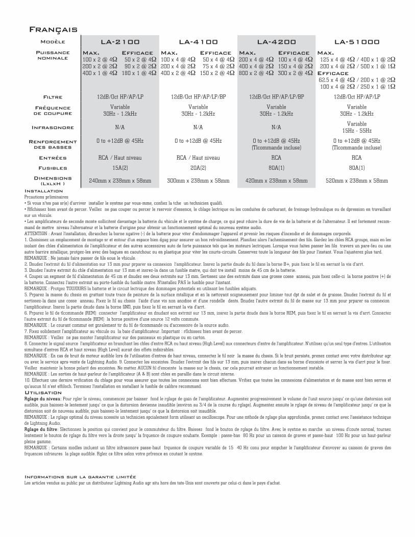
Modèle LA-2100 LA-4100 LA-4200 LA-51000Puissance nominale
Max.100 x 2 @ 4Ω200 x 2 @ 2Ω400 x 1 @ 4Ω
Efficace50 x 2 @ 4Ω90 x 2 @ 2Ω
180 x 1 @ 4Ω
Max.100 x 4 @ 4Ω200 x 4 @ 2Ω400 x 2 @ 4Ω
Efficace50 x 4 @ 4Ω75 x 4 @ 2Ω
150 x 2 @ 4Ω
Max.200 x 4 @ 4Ω400 x 4 @ 2Ω800 x 2 @ 4Ω
Efficace100 x 4 @ 4Ω150 x 4 @ 2Ω300 x 2 @ 4Ω
Max.125 x 4 @ 4Ω / 400 x 1 @ 2Ω200 x 4 @ 2Ω / 500 x 1 @ 1Ω
Efficace62.5 x 4 @ 4Ω / 200 x 1 @ 2Ω100 x 4 @ 2Ω / 250 x 1 @ 1Ω
Filtre 12dB/Oct HP/AP/LP 12dB/Oct HP/AP/LP/BP 12dB/Oct HP/AP/LP/BP 12dB/Oct HP/AP/LP
Fréquence de coupure
Variable 30Hz - 1.2kHz
Variable 30Hz - 1.2kHz
Variable 30Hz - 1.2kHz
Variable 30Hz - 1.2kHz
Infrasonore N/A N/A N/AVariable
15Hz - 55Hz
Renforcement des basses
0 to +12dB @ 45Hz 0 to +12dB @ 45Hz 0 to +12dB @ 45Hz(Télécommande incluse)
0 to +12dB @ 45Hz (Télécommande incluse)
Entrées RCA / Haut niveau RCA / Haut niveau RCA RCA
Fusibles 15A(2) 20A(2) 80A(1) 80A(1)
Dimensions (LxlxH ) 240mm x 238mm x 58mm 300mm x 238mm x 58mm 420mm x 238mm x 58mm 520mm x 238mm x 58mm
Français
InstallationPrécautions préliminaires • Si vous n’êtes pas sûr(e) d’arriver à installer le système par vous-même, confiez la tâche à un technicien qualifié. • Réfléchissez bien avant de percer. Veillez à ne pas couper ou percer le réservoir d’essence, le câblage électrique ou les conduites de carburant, de freinage hydraulique ou de dépression en travaillant sur un véhicule. • Les amplificateurs de seconde monte sollicitent davantage la batterie du véhicule et le système de charge, ce qui peut réduire la durée de vie de la batterie et de l’alternateur. Il est fortement recom-mandé de mettre à niveau l’alternateur et la batterie d’origine pour obtenir un fonctionnement optimal du nouveau système audio.ATTENTION : Avant l’installation, débranchez la borne négative (-) de la batterie pour éviter d’endommager l’appareil et prévenir les risques d’incendie et de dommages corporels.1. Choisissez un emplacement de montage sûr et entouré d’un espace bien dégagé pour assurer un bon refroidissement. Planifiez alors l’acheminement des fils. Gardez les câbles RCA groupés, mais en les isolant des câbles d’alimentation de l’amplificateur et des autres accessoires auto de forte puissance tels que les moteurs électriques. Lorsque vous faites passer les fils à travers un pare-feu ou une autre barrière métallique, protégez-les avec des bagues en caoutchouc ou en plastique pour éviter les courts-circuits. Conservez toute la longueur des fils pour l’instant. Vous l’ajusterez plus tard. REMARQUE : Ne jamais faire passer de fils sous le véhicule.2. Dénudez l’extrémité du fil d’alimentation sur 13 mm pour préparer sa connexion à l’amplificateur. Insérez la partie dénudée du fil dans la borne B+, puis fixez le fil en serrant la vis d’arrêt. 3. Dénudez l’autre extrémité du câble d’alimentation sur 13 mm et insérez-la dans un fusible maître, qui doit être installé à moins de 45 cm de la batterie.4. Coupez un segment de fil d’alimentation de 45 cm et dénudez ses deux extrémités sur 13 mm. Sertissez une des extrémités dans une grosse cosse à anneau, puis fixez celle-ci à la borne positive (+) de la batterie. Connectez l’autre extrémité au porte-fusible du fusible maître. N’installez PAS le fusible pour l’instant.REMARQUE : Protégez TOUJOURS la batterie et le circuit électrique des dommages potentiels en utilisant les fusibles adéquats.5. Préparez la masse du châssis en grattant toute trace de peinture de la surface métallique et en la nettoyant soigneusement pour éliminer tout dépôt de saleté et de graisse. Dénudez l’extrémité du fil et sertissez-la dans une cosse à anneau. Fixez le fil au châssis à l’aide d’une vis non anodisée et d’une rondelle à dents. Dénudez l’autre extrémité du fil de masse sur 13 mm pour préparer sa connexion à l’amplificateur. Insérez la partie dénudée dans la borne GND, puis fixez le fil en serrant la vis d’arrêt.6. Préparez le fil de télécommande (REM) à connecter à l’amplificateur en dénudant son extrémité sur 13 mm, insérez la partie dénudée dans la borne REM, puis fixez le fil en serrant la vis d’arrêt. Connectez l’autre extrémité du fil de télécommande (REM) à la borne positive d’une source 12 volts commutée. REMARQUE : Le courant commuté est généralement tiré du fil de télécommande ou d’accessoire de la source audio.7. Fixez solidement l’amplificateur au véhicule ou à la baie d’amplificateur. Important : réfléchissez bien avant de percer. REMARQUE : Veillez à ne pas monter l’amplificateur sur des panneaux en plastique ou en carton.8. Connectez le signal source à l’amplificateur en branchant les câbles d’entrée RCA ou haut niveau (High Level) aux connecteurs d’entrée de l’amplificateur. N’utilisez qu’un seul type d’entrées. L’utilisation simultanée d’entrées RCA et haut niveau (High Level) aurait des effets indésirables. REMARQUE : En cas de bruit de moteur audible lors de l’utilisation d’entrées de haut niveau, connectez le fil noir à la masse du châssis. Si le bruit persiste, prenez contact avec votre distributeur agréé ou avec le service après-vente de Lightning Audio. 9. Connectez les enceintes. Dénudez l’extrémité des fils sur 13 mm, puis insérez chacun dans sa borne d’enceinte et serrez la vis d’arrêt pour le fixer. Veillez à maintenir la bonne polarité des enceintes. Ne mettez AUCUN fil d’enceinte à la masse sur le châssis, car cela pourrait entraîner un fonctionnement instable. REMARQUE : Les sorties de haut-parleur de l’amplificateur (A & B) sont câblées en parallèle dans le circuit interne.10. Effectuez une dernière vérification du câblage pour vous assurer que toutes les connexions sont bien effectuées. Vérifiez que toutes les connexions d’alimentation et de masse sont bien serrées et qu’aucun fil n’est effiloché. Terminez l’installation en installant le fusible de calibre recommandé.
UtilisationRglage du niveau:– Pour régler le niveau, commencez par baisser à fond le réglage de gain de l’amplificateur. Augmentez progressivement le volume de l’unité source jusqu’à ce qu’une distorsion soit audible, puis baissez-le lentement jusqu’à ce que la distorsion devienne inaudible (environ au 3/4 de la course du réglage). Augmentez ensuite le réglage de niveau de l’amplificateur jusqu’à ce que la distorsion soit de nouveau audible, puis baissez-le lentement jusqu’à ce que la distorsion soit inaudible. REMARQUE : Le réglage optimal du niveau nécessite un technicien spécialement formé utilisant un oscilloscope. Pour une méthode de réglage plus approfondie, prenez contact avec l’assistance technique de Lightning Audio. Rglage du filtre:– Sélectionnez la position qui convient pour le commutateur du filtre. Baissez à fond le bouton de réglage du filtre. Avec le système en marche à un niveau d’écoute normal, tournez lentement le bouton de réglage du filtre vers la droite jusqu’à la fréquence de coupure souhaitée. Exemple : passe-bas à 80 Hz pour un caisson de graves et passe-haut à 100 Hz pour un haut-parleur pleine gamme.REMARQUE : Certains modèles incluent un filtre infrasonore passe-haut à fréquence de coupure variable de 15 à 40 Hz conçu pour empêcher le l’amplificateur d’envoyer au caisson de graves des fréquences inférieures à la plage audible. Réglez ce filtre selon votre préférence en écoutant le système.
Informations sur la garantie limitée Les articles vendus au public par un distributeur Lightning Audio agréé situé hors des États-Unis sont couverts par celui-ci dans le pays d’achat.
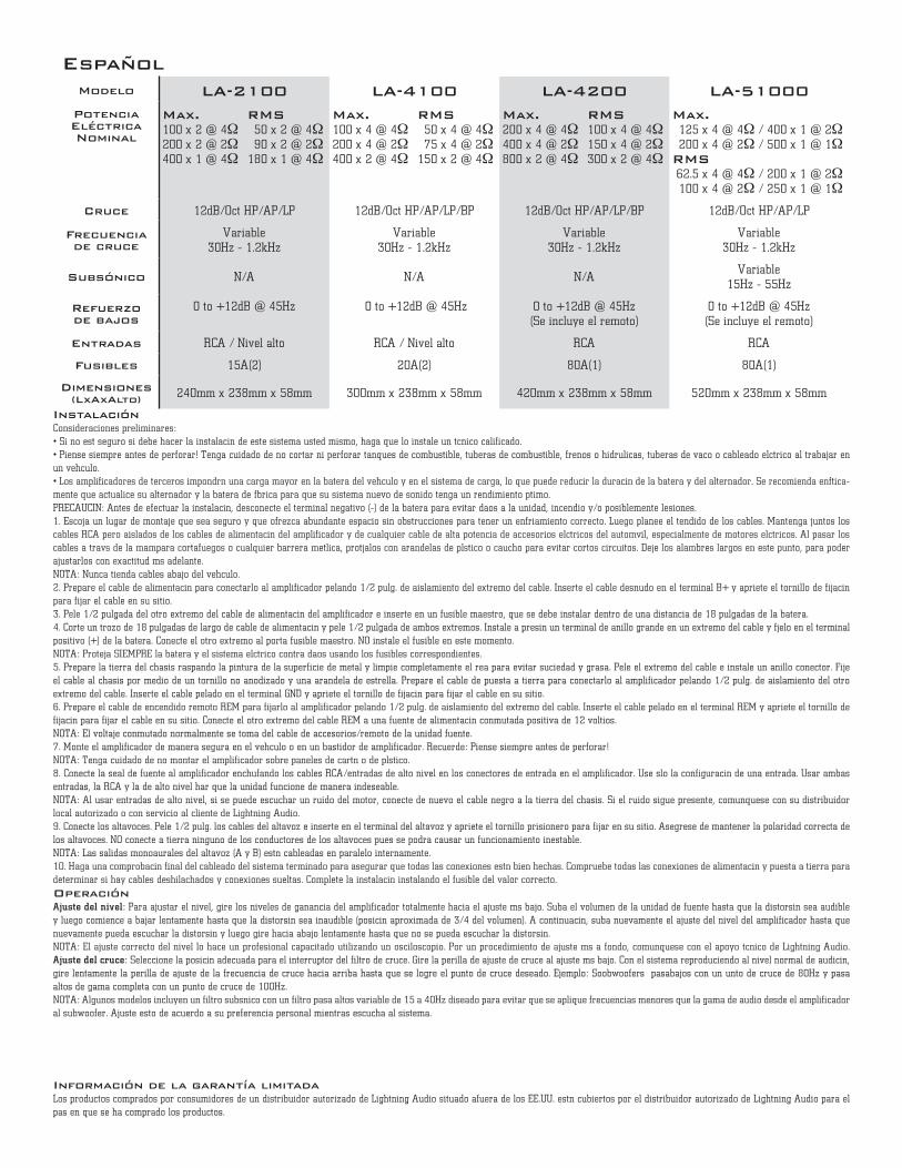
Modelo LA-2100 LA-4100 LA-4200 LA-51000Potencia Eléctrica Nominal
Max.100 x 2 @ 4Ω200 x 2 @ 2Ω400 x 1 @ 4Ω
RMS50 x 2 @ 4Ω90 x 2 @ 2Ω
180 x 1 @ 4Ω
Max.100 x 4 @ 4Ω200 x 4 @ 2Ω400 x 2 @ 4Ω
RMS50 x 4 @ 4Ω75 x 4 @ 2Ω
150 x 2 @ 4Ω
Max.200 x 4 @ 4Ω400 x 4 @ 2Ω800 x 2 @ 4Ω
RMS100 x 4 @ 4Ω150 x 4 @ 2Ω300 x 2 @ 4Ω
Max.125 x 4 @ 4Ω / 400 x 1 @ 2Ω200 x 4 @ 2Ω / 500 x 1 @ 1Ω
RMS62.5 x 4 @ 4Ω / 200 x 1 @ 2Ω100 x 4 @ 2Ω / 250 x 1 @ 1Ω
Cruce 12dB/Oct HP/AP/LP 12dB/Oct HP/AP/LP/BP 12dB/Oct HP/AP/LP/BP 12dB/Oct HP/AP/LP
Frecuencia de cruce
Variable 30Hz - 1.2kHz
Variable 30Hz - 1.2kHz
Variable 30Hz - 1.2kHz
Variable 30Hz - 1.2kHz
Subsónico N/A N/A N/AVariable
15Hz - 55Hz
Refuerzo de bajos
0 to +12dB @ 45Hz 0 to +12dB @ 45Hz 0 to +12dB @ 45Hz(Se incluye el remoto)
0 to +12dB @ 45Hz (Se incluye el remoto)
Entradas RCA / Nivel alto RCA / Nivel alto RCA RCA
Fusibles 15A(2) 20A(2) 80A(1) 80A(1)
Dimensiones (LxAxAlto) 240mm x 238mm x 58mm 300mm x 238mm x 58mm 420mm x 238mm x 58mm 520mm x 238mm x 58mm
Español
InstalaciónConsideraciones preliminares: • Si no está seguro si debe hacer la instalación de este sistema usted mismo, haga que lo instale un técnico calificado. • ¡Piense siempre antes de perforar! Tenga cuidado de no cortar ni perforar tanques de combustible, tuberías de combustible, frenos o hidráulicas, tuberías de vacío o cableado eléctrico al trabajar en un vehículo. • Los amplificadores de terceros impondrán una carga mayor en la batería del vehículo y en el sistema de carga, lo que puede reducir la duración de la batería y del alternador. Se recomienda enfática-mente que actualice su alternador y la batería de fábrica para que su sistema nuevo de sonido tenga un rendimiento óptimo.PRECAUCIÓN: Antes de efectuar la instalación, desconecte el terminal negativo (-) de la batería para evitar daños a la unidad, incendio y/o posiblemente lesiones.1. Escoja un lugar de montaje que sea seguro y que ofrezca abundante espacio sin obstrucciones para tener un enfriamiento correcto. Luego planee el tendido de los cables. Mantenga juntos los cables RCA pero aislados de los cables de alimentación del amplificador y de cualquier cable de alta potencia de accesorios eléctricos del automóvil, especialmente de motores eléctricos. Al pasar los cables a través de la mampara cortafuegos o cualquier barrera metálica, protéjalos con arandelas de plástico o caucho para evitar cortos circuitos. Deje los alambres largos en este punto, para poder ajustarlos con exactitud más adelante. NOTA: Nunca tienda cables abajo del vehículo.2. Prepare el cable de alimentación para conectarlo al amplificador pelando 1/2 pulg. de aislamiento del extremo del cable. Inserte el cable desnudo en el terminal B+ y apriete el tornillo de fijación para fijar el cable en su sitio. 3. Pele 1/2 pulgada del otro extremo del cable de alimentación del amplificador e inserte en un fusible maestro, que se debe instalar dentro de una distancia de 18 pulgadas de la batería. 4. Corte un trozo de 18 pulgadas de largo de cable de alimentación y pele 1/2 pulgada de ambos extremos. Instale a presión un terminal de anillo grande en un extremo del cable y fíjelo en el terminal positivo (+) de la batería. Conecte el otro extremo al porta fusible maestro. NO instale el fusible en este momento. NOTA: Proteja SIEMPRE la batería y el sistema eléctrico contra daños usando los fusibles correspondientes.5. Prepare la tierra del chasis raspando la pintura de la superficie de metal y limpie completamente el área para evitar suciedad y grasa. Pele el extremo del cable e instale un anillo conector. Fije el cable al chasis por medio de un tornillo no anodizado y una arandela de estrella. Prepare el cable de puesta a tierra para conectarlo al amplificador pelando 1/2 pulg. de aislamiento del otro extremo del cable. Inserte el cable pelado en el terminal GND y apriete el tornillo de fijación para fijar el cable en su sitio.6. Prepare el cable de encendido remoto REM para fijarlo al amplificador pelando 1/2 pulg. de aislamiento del extremo del cable. Inserte el cable pelado en el terminal REM y apriete el tornillo de fijación para fijar el cable en su sitio. Conecte el otro extremo del cable REM a una fuente de alimentación conmutada positiva de 12 voltios. NOTA: El voltaje conmutado normalmente se toma del cable de accesorios/remoto de la unidad fuente.7. Monte el amplificador de manera segura en el vehículo o en un bastidor de amplificador. Recuerde: ¡Piense siempre antes de perforar! NOTA: Tenga cuidado de no montar el amplificador sobre paneles de cartón o de plástico.8. Conecte la señal de fuente al amplificador enchufando los cables RCA/entradas de alto nivel en los conectores de entrada en el amplificador. Use sólo la configuración de una entrada. Usar ambas entradas, la RCA y la de alto nivel hará que la unidad funcione de manera indeseable. NOTA: Al usar entradas de alto nivel, si se puede escuchar un ruido del motor, conecte de nuevo el cable negro a la tierra del chasis. Si el ruido sigue presente, comuníquese con su distribuidor local autorizado o con servicio al cliente de Lightning Audio. 9. Conecte los altavoces. Pele 1/2 pulg. los cables del altavoz e inserte en el terminal del altavoz y apriete el tornillo prisionero para fijar en su sitio. Asegúrese de mantener la polaridad correcta de los altavoces. NO conecte a tierra ninguno de los conductores de los altavoces pues se podría causar un funcionamiento inestable. NOTA: Las salidas monoaurales del altavoz (A y B) están cableadas en paralelo internamente.10. Haga una comprobación final del cableado del sistema terminado para asegurar que todas las conexiones estén bien hechas. Compruebe todas las conexiones de alimentación y puesta a tierra para determinar si hay cables deshilachados y conexiones sueltas. Complete la instalación instalando el fusible del valor correcto.
OperaciónAjuste del nivel: Para ajustar el nivel, gire los niveles de ganancia del amplificador totalmente hacia el ajuste más bajo. Suba el volumen de la unidad de fuente hasta que la distorsión sea audible y luego comience a bajar lentamente hasta que la distorsión sea inaudible (posición aproximada de 3/4 del volumen). A continuación, suba nuevamente el ajuste del nivel del amplificador hasta que nuevamente pueda escuchar la distorsión y luego gire hacia abajo lentamente hasta que no se pueda escuchar la distorsión. NOTA: El ajuste correcto del nivel lo hace un profesional capacitado utilizando un osciloscopio. Por un procedimiento de ajuste más a fondo, comuníquese con el apoyo técnico de Lightning Audio. Ajuste del cruce: Seleccione la posición adecuada para el interruptor del filtro de cruce. Gire la perilla de ajuste de cruce al ajuste más bajo. Con el sistema reproduciendo al nivel normal de audición, gire lentamente la perilla de ajuste de la frecuencia de cruce hacia arriba hasta que se logre el punto de cruce deseado. Ejemplo: Soobwoofers – pasabajos con un unto de cruce de 80Hz y pasa altos de gama completa con un punto de cruce de 100Hz.NOTA: Algunos modelos incluyen un filtro subsónico con un filtro pasa altos variable de 15 a 40Hz diseñado para evitar que se aplique frecuencias menores que la gama de audio desde el amplificador al subwoofer. Ajuste esto de acuerdo a su preferencia personal mientras escucha al sistema.
Información de la garantía limitada Los productos comprados por consumidores de un distribuidor autorizado de Lightning Audio situado afuera de los EE.UU. están cubiertos por el distribuidor autorizado de Lightning Audio para el país en que se ha comprado los productos.
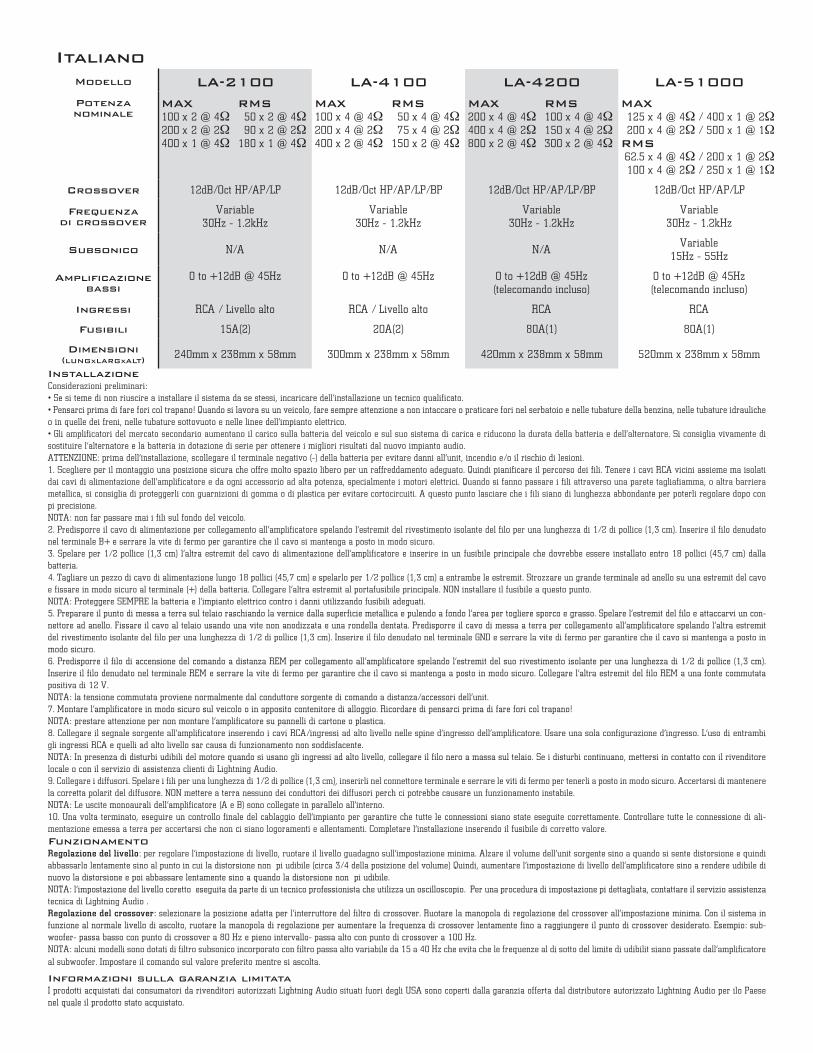
Modello LA-2100 LA-4100 LA-4200 LA-51000Potenza nominale
MAX100 x 2 @ 4Ω200 x 2 @ 2Ω400 x 1 @ 4Ω
RMS50 x 2 @ 4Ω90 x 2 @ 2Ω
180 x 1 @ 4Ω
MAX100 x 4 @ 4Ω200 x 4 @ 2Ω400 x 2 @ 4Ω
RMS50 x 4 @ 4Ω75 x 4 @ 2Ω
150 x 2 @ 4Ω
MAX200 x 4 @ 4Ω400 x 4 @ 2Ω800 x 2 @ 4Ω
RMS100 x 4 @ 4Ω150 x 4 @ 2Ω300 x 2 @ 4Ω
MAX125 x 4 @ 4Ω / 400 x 1 @ 2Ω200 x 4 @ 2Ω / 500 x 1 @ 1Ω
RMS62.5 x 4 @ 4Ω / 200 x 1 @ 2Ω100 x 4 @ 2Ω / 250 x 1 @ 1Ω
Crossover 12dB/Oct HP/AP/LP 12dB/Oct HP/AP/LP/BP 12dB/Oct HP/AP/LP/BP 12dB/Oct HP/AP/LP
Frequenza di crossover
Variable 30Hz - 1.2kHz
Variable 30Hz - 1.2kHz
Variable 30Hz - 1.2kHz
Variable 30Hz - 1.2kHz
Subsonico N/A N/A N/AVariable
15Hz - 55Hz
Amplificazione bassi
0 to +12dB @ 45Hz 0 to +12dB @ 45Hz 0 to +12dB @ 45Hz(telecomando incluso)
0 to +12dB @ 45Hz (telecomando incluso)
Ingressi RCA / Livello alto RCA / Livello alto RCA RCA
Fusibili 15A(2) 20A(2) 80A(1) 80A(1)
Dimensioni (LUNGxLARGxALT) 240mm x 238mm x 58mm 300mm x 238mm x 58mm 420mm x 238mm x 58mm 520mm x 238mm x 58mm
Italiano
InstallazioneConsiderazioni preliminari: • Se si teme di non riuscire a installare il sistema da se stessi, incaricare dell’installazione un tecnico qualificato. • Pensarci prima di fare fori col trapano! Quando si lavora su un veicolo, fare sempre attenzione a non intaccare o praticare fori nel serbatoio e nelle tubature della benzina, nelle tubature idrauliche o in quelle dei freni, nelle tubature sottovuoto e nelle linee dell’impianto elettrico. • Gli amplificatori del mercato secondario aumentano il carico sulla batteria del veicolo e sul suo sistema di carica e riducono la durata della batteria e dell’alternatore. Si consiglia vivamente di sostituire l’alternatore e la batteria in dotazione di serie per ottenere i migliori risultati dal nuovo impianto audio.ATTENZIONE: prima dell’installazione, scollegare il terminale negativo (-) della batteria per evitare danni all’unità, incendio e/o il rischio di lesioni.1. Scegliere per il montaggio una posizione sicura che offre molto spazio libero per un raffreddamento adeguato. Quindi pianificare il percorso dei fili. Tenere i cavi RCA vicini assieme ma isolati dai cavi di alimentazione dell’amplificatore e da ogni accessorio ad alta potenza, specialmente i motori elettrici. Quando si fanno passare i fili attraverso una parete tagliafiamma, o altra barriera metallica, si consiglia di proteggerli con guarnizioni di gomma o di plastica per evitare cortocircuiti. A questo punto lasciare che i fili siano di lunghezza abbondante per poterli regolare dopo con più precisione. NOTA: non far passare mai i fili sul fondo del veicolo.2. Predisporre il cavo di alimentazione per collegamento all’amplificatore spelando l’estremità del rivestimento isolante del filo per una lunghezza di 1/2 di pollice (1,3 cm). Inserire il filo denudato nel terminale B+ e serrare la vite di fermo per garantire che il cavo si mantenga a posto in modo sicuro. 3. Spelare per 1/2 pollice (1,3 cm) l’altra estremità del cavo di alimentazione dell’amplificatore e inserire in un fusibile principale che dovrebbe essere installato entro 18 pollici (45,7 cm) dalla batteria.4. Tagliare un pezzo di cavo di alimentazione lungo 18 pollici (45,7 cm) e spelarlo per 1/2 pollice (1,3 cm) a entrambe le estremità. Strozzare un grande terminale ad anello su una estremità del cavo e fissare in modo sicuro al terminale (+) della batteria. Collegare l’altra estremità al portafusibile principale. NON installare il fusibile a questo punto.NOTA: Proteggere SEMPRE la batteria e l’impianto elettrico contro i danni utilizzando fusibili adeguati.5. Preparare il punto di messa a terra sul telaio raschiando la vernice dalla superficie metallica e pulendo a fondo l’area per togliere sporco e grasso. Spelare l’estremità del filo e attaccarvi un con-nettore ad anello. Fissare il cavo al telaio usando una vite non anodizzata e una rondella dentata. Predisporre il cavo di messa a terra per collegamento all’amplificatore spelando l’altra estremità del rivestimento isolante del filo per una lunghezza di 1/2 di pollice (1,3 cm). Inserire il filo denudato nel terminale GND e serrare la vite di fermo per garantire che il cavo si mantenga a posto in modo sicuro.6. Predisporre il filo di accensione del comando a distanza REM per collegamento all’amplificatore spelando l’estremità del suo rivestimento isolante per una lunghezza di 1/2 di pollice (1,3 cm). Inserire il filo denudato nel terminale REM e serrare la vite di fermo per garantire che il cavo si mantenga a posto in modo sicuro. Collegare l’altra estremità del filo REM a una fonte commutata positiva di 12 V. NOTA: la tensione commutata proviene normalmente dal conduttore sorgente di comando a distanza/accessori dell’unità.7. Montare l’amplificatore in modo sicuro sul veicolo o in apposito contenitore di alloggio. Ricordare di pensarci prima di fare fori col trapano! NOTA: prestare attenzione per non montare l’amplificatore su pannelli di cartone o plastica.8. Collegare il segnale sorgente all’amplificatore inserendo i cavi RCA/ingressi ad alto livello nelle spine d’ingresso dell’amplificatore. Usare una sola configurazione d’ingresso. L’uso di entrambi gli ingressi RCA e quelli ad alto livello sarà causa di funzionamento non soddisfacente.NOTA: In presenza di disturbi udibili del motore quando si usano gli ingressi ad alto livello, collegare il filo nero a massa sul telaio. Se i disturbi continuano, mettersi in contatto con il rivenditore locale o con il servizio di assistenza clienti di Lightning Audio.9. Collegare i diffusori. Spelare i fili per una lunghezza di 1/2 di pollice (1,3 cm), inserirli nel connettore terminale e serrare le viti di fermo per tenerli a posto in modo sicuro. Accertarsi di mantenere la corretta polarità del diffusore. NON mettere a terra nessuno dei conduttori dei diffusori perché ciò potrebbe causare un funzionamento instabile. NOTA: Le uscite monoaurali dell’amplificatore (A e B) sono collegate in parallelo all’interno. 10. Una volta terminato, eseguire un controllo finale del cablaggio dell’impianto per garantire che tutte le connessioni siano state eseguite correttamente. Controllare tutte le connessione di ali-mentazione emessa a terra per accertarsi che non ci siano logoramenti e allentamenti. Completare l’installazione inserendo il fusibile di corretto valore.
FunzionamentoRegolazione del livello: per regolare l’impostazione di livello, ruotare il livello guadagno sull’impostazione minima. Alzare il volume dell’unità sorgente sino a quando si sente distorsione e quindi abbassarlo lentamente sino al punto in cui la distorsione non è più udibile (circa 3/4 della posizione del volume) Quindi, aumentare l’impostazione di livello dell’amplificatore sino a rendere udibile di nuovo la distorsione e poi abbassare lentamente sino a quando la distorsione non è più udibile. NOTA: l’impostazione del livello coretto è eseguita da parte di un tecnico professionista che utilizza un oscilloscopio. Per una procedura di impostazione più dettagliata, contattare il servizio assistenza tecnica di Lightning Audio .Regolazione del crossover: selezionare la posizione adatta per l’interruttore del filtro di crossover. Ruotare la manopola di regolazione del crossover all’impostazione minima. Con il sistema in funzione al normale livello di ascolto, ruotare la manopola di regolazione per aumentare la frequenza di crossover lentamente fino a raggiungere il punto di crossover desiderato. Esempio: sub-woofer- passa basso con punto di crossover a 80 Hz e pieno intervallo- passa alto con punto di crossover a 100 Hz.NOTA: alcuni modelli sono dotati di filtro subsonico incorporato con filtro passa alto variabile da 15 a 40 Hz che evita che le frequenze al di sotto del limite di udibilità siano passate dall’amplificatore
al subwoofer. Impostare il comando sul valore preferito mentre si ascolta.
Informazioni sulla garanzia limitata I prodotti acquistati dai consumatori da rivenditori autorizzati Lightning Audio situati fuori degli USA sono coperti dalla garanzia offerta dal distributore autorizzato Lightning Audio per ilo Paese nel quale il prodotto stato acquistato.
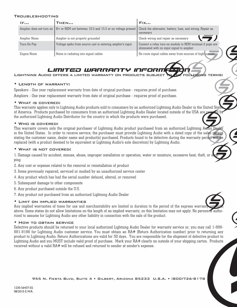
Limited Warranty Information Lightning Audio offers a limited warranty on products subject to the following terms:
• Length of warranty:Speakers - One year replacement warranty from date of original purchase - requires proof of purchase.
Amplifiers - One year replacement warranty from date of original purchase - requires proof of purchase.
• What is covered:This warranty applies only to Lightning Audio products sold to consumers by an authorized Lightning Audio Dealer in the United States of America. Products purchased by consumers from an authorized Lightning Audio Dealer located outside of the USA are covered by the authorized Lightning Audio Distributor for the country in which the products were purchased.
• Who is covered: This warranty covers only the original purchaser of Lightning Audio product purchased from an authorized Lightning Audio Dealer in the United States. In order to receive service, the purchaser must provide Lightning Audio with a dated copy of the sales receipt stating the customer name, dealer name and product(s) purchased. Products found to be defective during the warranty period will be replaced (with a product deemed to be equivalent at Lightning Audio’s sole discretion) by Lightning Audio.
• What is not covered: 1. Damage caused by accident, misuse, abuse, improper installation or operation, water or moisture, excessive heat, theft, or ship-ping
2. Any cost or expense related to the removal or reinstallation of product
3. Items previously repaired, serviced or modified by an unauthorized service center
4. Any product which has had the serial number defaced, altered, or removed
5. Subsequent damage to other components
6. Any product purchased outside the U.S.
7. Any product not purchased from an authorized Lightning Audio Dealer • Limit on implied warranties Any implied warranties of fitness for use and merchantability are limited in duration to the period of the express warranty set forth above. Some states do not allow limitations on the length of an implied warranty, so this limitation may not apply. No person is autho-rized to assume for Lightning Audio any other liability in connection with the sale of the product.
• How to obtain service Defective products should be returned to your local authorized Lightning Audio Dealer for warranty service or, you may call 1-888-881-8186 for Lightning Audio customer service. You must obtain an RA# (Return Authorization number) prior to returning any product to Lightning Audio. Return Authorizations are valid for 30 days. You are responsible for the shipment of defective product to Lightning Audio and you MUST include valid proof of purchase. Mark your RA# clearly on outside of your shipping carton. Products received without a valid RA# will be refused and returned to sender at sender’s expense.
955 N. Fiesta Blvd, Suite 4 • Gilbert, Arizona 85233 U.S.A. • (800)726-8178
If... Then... Fix...Amplifier does not turn on B+ or REM not between 10.5 and 15.5 or no voltage present Check the alternator, battery, fuse, and wiring. Repair as
necessary
Amplifier Noise Amplifier is not properly grounded Check wiring and repair as necessary
Turn-On Pop Voltage spike from source unit is entering amplifier’s input Connect a relay turn-on module to REM terminal if pops are eliminated with no input signal to amplifier
Engine Noise Noise is radiating into signal cables Re-route signal cables away from sources of high current
Troubleshooting
1230-56437-0208/2010 E.W.R.