Embed Size (px)
Citation preview

6
Amphibious NDT Robots
Tariq P. Sattar, Hernando E. Leon-Rodriguez and Jianzhong Shang London South Bank University
United Kingdom
1. Introduction
Oil, petrochemical, and food processing industries worldwide store their raw materials and product in tens of thousands of storage tanks. The tanks are mostly constructed using welded steel plates and therefore subject to corrosion and weld cracking. Testing the structural integrity of these storage tanks with non-destructive testing (NDT) techniques is an expensive and time consuming activity. The walls of a large tank can usually be tested manually (for corrosion thinning and weld defects using ultrasonic techniques) from outside the tank. Access to most areas of a wall is obtained by constructing scaffolding or abseiling down from the top. However, erecting scaffolding is expensive and the inspection is tedious and slow. These costs can be reduced and the inspection speeded up by using climbing robots that deploy ultrasonic probes with scanning arms. However, there are some areas of the wall that cannot be accessed from the outside, for example at the base where the walls are protected by striker plates to run off rain water, or behind wind girders around the tank that are used to strengthen the tank, or obviously in tanks that are partially or fully buried in the ground. Similarly, storage tanks on ships cannot be inspected from the outside because they are surrounded by ballast tanks. To inspect the walls in these cases, the inspection has to be performed from inside the tank. Additionally, a primary source of trouble in tanks is the floor which can corrode quickly in localised areas due to ground chemistry and suffer damage to welds through soil movement. The floors can be inspected reliably only by entering the tank. Entry into tanks can be performed only when the tank has been emptied and thoroughly cleaned when it contains hazardous materials. The operation is hugely expensive requiring transportation of product to other tanks or locations, outages that last many months with subsequent loss of revenue, and cleaning costs incurred by repeated cleaning of the tank till all product is removed. Very large cost savings can be made by performing internal and in-service inspection of the walls and floors of storage tanks by using robots that can be inserted into a tank through manholes. The robots will have to operate in the product contained in the tank (e.g. crude oil, refined petroleum products, chemicals, liquors, etc.) and the robot should be capable of gaining access to target areas that are to be inspected (tank wall areas, floor areas, and welds on the walls or floor). O
pen
Acc
ess
Dat
abas
ew
ww
.i-te
chon
line.
com
Source: Climbing & Walking Robots, Towards New Applications, Book edited by Houxiang Zhang,ISBN 978-3-902613-16-5, pp.546, October 2007, Itech Education and Publishing, Vienna, Austria

Climbing & Walking Robots, Towards New Applications 128
To further reduce the cost of inspection, the robots should be versatile so that the same robot can perform many types of inspection once inserted into a tank. Also, the robots should be able to work in different types and sizes of tank. A versatile robot will be required to be compact so that it can be inserted through the smallest manhole and operate in small spaces. It should be able to swim through the product to provide access to a given inspection target, climb on the walls of the tank when these are to be inspected, and it should be able to descend onto the floor and move around on it with controlled motion trajectories. It should be able to operate in air on the floor when a tank is emptied of most of its product leaving only an inch or two of product on the floor. This latter scenario is useful because a tank product can be drawn off relatively easily but cleaning the tank till all product is removed is extremely difficult. Therefore the ability to operate on the floor of a tank with a few inches of liquid submerging the NDT sensors and acting as a couplant between the UT probe and the floor plates will still save the costs of cleaning and obviate the need for supplying a couplant. Finally, the robot should be intrinsically safe when operating in flammable and explosive environments. This chapter describes some robot designs that aim to accomplish these requirements. Two wall-climbing, floor moving and swimming robots are described that operate while submerged in liquids stored in oil and petrochemical storage tanks. It outlines, in section 2, the industrial requirements for deploying a range of non-destructive testing (NDT) probes and techniques on the floors and walls of storage tanks while operating in liquids or in air, in explosive environments, and in cluttered and constrained spaces. The design of two robots that have been developed to satisfy these requirements is explained in detail in sections 2.4 and 3. NDT results obtained with the robotic systems are presented.Some other robots that have been developed to inspect tank floors are “Maverick” produced by Solex Robotics in USA, “Tank Ray” produced by Raytheon in the USA and “OTIS” produced by In Tank Services, (Berger et al 1990; Schempf 1994; King et al 1992; Solex Robotics).
2. Design of Floor and Wall Climbing Robot, RobTank, to Inspect the Internal Walls and Floors of Oil and Petrochemical Storage Tanks
This section describes a robot that is designed to enter a wide variety of storage tanks when in service and inspect the floor and internal walls of the tank while submerged in the product liquid.
2.1 Robotic NDT in Oil and Petrochemical Storage Tanks
Leakages from the floor of oil and chemical storage tanks lead to pollution and soil contamination. It is therefore essential to periodically inspect the floor to decide when to take a tank out of operation and repair it. Current inspection practices require tanks to be emptied and cleaned before an inspection can commence (Rusing 1994; Raad 1994). The total time to empty, clean and inspect a storage tank can be between 1 to 9 months on the larger crude oil tanks. Despite safety procedures, the cleaning operators are exposed to hazardous chemicals and other hazardous conditions for long periods of time. Tanks can remain out of service for quite long periods with direct economic and operational implications. Huge savings in cost and inspection times could be obtained by performing in-service inspection
Amphibious NDT Robots 129
of tank floors and walls with robotic devices. Given the large variety and types of storage tanks, to achieve this inspection it is necessary to develop mobile robots capable of: - Entering tanks through manhole openings that can be as small as 300 mm diameter. - Traveling on uneven tank surfaces and through sediment layers on the floor. - Deploying a payload of Non Destructive Testing (NDT) sensors for the inspection of top and bottom corrosion on the tank floor. - Changing surfaces from the floor to the wall to inspect lower parts of the tank that may be inaccessible from outside. - Operating in explosive and hazardous liquids such as crude oil, petroleum products, ammonia, etc. - Navigating in the tank to locate the position of defects and avoiding obstacles. The design of robotics to perform inspection of storage tanks depends on whether the products in a tank are clean or dirty: (a) Clean storage tanks containing blended oil products or chemicals. The size of this type of tank varies from about 2 to 20 meters in diameter and usually has a fixed roof. Spot readings are taken on the floor, patch and annular plates in a ‘domino’ pattern with ultrasonic thickness measurements (USTM). Any suspect areas and other critical items such as drain sumps are then scanned manually. The inspection authority or utility operator can vary the amount of NDT carried out based on the initial results. This method does have the drawback that isolated areas of under floor corrosion could remain undetected. On the larger diameter tanks, magnetic flux leakage (MFL) is used for the initial inspection. A portable trolley with an array of sensors is pushed manually over the floor to detect 40% thickness loss. Detected plate thinning is marked with paint by an operator for further evaluation. Floor plate closer than 75 mm to the tank wall is inspected with a hand held unit. Suspect areas are further examined using either vacuum box or magnetic particle inspection methods. (b) Crude and fuel oil storage tanks Crude oil tanks that have not been opened for cleaning for five or more years usually have large deposits of sludge (wax and sand) that can be up to 5 meters deep. These tanks have floating roofs, either double skin or pontoon type, with many manhole openings (for agitator entry). The diameter of these tanks is between 20 and 100 meters and construction material is carbon steel. They have annular floor plates with a minimum thickness of 12.5mm. Central floor plate thickness may vary between 6 to 12mm. The preparation periods for entry and internal inspection are lengthy with 6-9 months required for removal of the oil, gas, and sludge banks. Another 3-6 months are required for the process of washing the tank clean of all oil and venting it before men can enter the tank. The cleaned tank is inspected visually, then with Magnetic Flux Leakage (MFL) or Low Frequency Eddy-Current techniques to find problem areas, and finally UT is used to validate the findings. Dependent on technique, annular floor plate thickness up to 35mm can be achieved with discrimination between topside and under floor corrosion. Examination of floor plate welds is a time consuming and difficult task due to residue of product and poor lighting condition. Fuel oil storage tanks may be fitted with heating coils (usually 50mm diameter steam pipes), which hamper floor inspection. Many of these large diameter tanks have steel girders welded around the tank perimeter between half and two-thirds its height to strengthen the

Climbing & Walking Robots, Towards New Applications 130
tank. Unless adequate drainage is provided, they become water traps and subsequent corrosion sites.
2.2 Intrinsic Safety of a Robot in Explosive Environments
For a robot to operate safely in a flammable and explosive environment, its design is constrained by the overriding need to make it intrinsically safe. To meet BASEEFA requirements for Certification of the robot as intrinsically safe, all electronics, drive motors, and shaft encoders on board the robot must be housed in a single enclosure that is sealed and purged with inert gases so that oxygen is removed from the enclosure. A system to sense the pressure in the enclosure and cut-off power supply to the robot at the operator’s end, when pressure falls below a threshold value, must be incorporated. There is an explosion risk in the “Vapor” zone when inserting a robot into a tank. One solution is to use a purged funnel through which the robot is passed into the liquid. The robot must be constructed with materials that prevent build up of electrical static and should avoid sharp corners where a discharge could occur.
2.3 Buoyancy in Water and in Crude Oil
The buoyancy of swimming and wall-climbing robots operating in liquids depends on the density of a particular liquid. A versatile robot that can operate in many liquids ranging from water to crude oil therefore needs to actively control its buoyancy. The oil industry uses API gravity as a measure of crude density. This is an inverse measure, the higher the API number, the lower the density. The API gravity is given by equation 1:
131.5F60atgravityspecific
141.5gravityAPI −= (1)
Where, specific gravity is the ratio of density of oil to density of water. Light crude oil has a API gravity of more than 40. At API = 40, density of water is 998 kg m-3, the density of light crude is 823.42 kg m-3. Heavy crude oil, typically API gravity of 20 or less, has a density of 932.13 kg m-3 (For comparison, the density of olive oil is 920 kg m-3).A robot designed to be neutrally buoyant in water (with either mass or volume control), will experience a negative buoyancy force in oil. For example, if the robot weight in air is 998 kg and its volume is 1 m3, it will be neutrally buoyant in water but will experience a negative force of 66 kg in heavy crude with API gravity of 20. The same robot in light crude API gravity of 40, will experience a negative buoyancy force of 175 kg. It is helpful to make a wall-climbing robot neutrally buoyant so that gravity forces are unimportant. When swimming, the robot buoyancy can be altered around its neutral buoyancy to ascend and descend the robot or varied rapidly to regulate its depth at a given set-point. It needs to be negatively buoyant when inspecting the floor so that it can apply sufficient pressure for good traction and contact of ultrasonic NDT sensors in the form of wheel probes. In conclusion, sufficient range of mass or volume change should be designed into the buoyancy tanks to enable the same robot to operate in all types of liquid with neutral buoyancy when climbing walls and with negative buoyancy when on the floor.

Amphibious NDT Robots 131
2.4 Tank Floor and Wall Inspection with Entry into the Tank by RobTank
“Rob Tank Inspec” is a European project that has developed a robot called RobTank for in-service inspection of storage tanks filled with hazardous liquids. The robotic system is intended for largely clean tanks with a sediment layer on the floor that is not more than 50 mm thick. The applied inspection methods allow the evaluation of tank floor and wall condition in order to prevent leakage situations or prioritize maintenance works. The mobile robot and its payload of NDT sensors and instrumentation are designed to test the following target areas: - Under base corrosion: The fitting of shielding plates (to run off rain water) prevents access from the outside to under-wall corrosion areas. Current practice is to fit shielding plates to all tanks that are refurbished. The inspection robot deployed internally can provide access to this area of the annular plate. - Sump drains: Another area of corrosion. The area requires scan inspection rather than spot inspection. - Wind girders: Another area of corrosion. Can be inspected manually from the inside on floating roofs when roof falls below girder level. However, fixed roof tanks require inspection by a robot that may be operates both in liquid as well as air depending on whether the inspection is being performed in-service or on a tank that has been emptied for cleaning. - Under heavier deposits of sludge: Experience has shown that likely areas of corrosion in crude oil tanks are to be found in areas where there is a heavy deposit of sludge. - Under heating coils (steam coils): The area under heating coils in crude oil tanks is a particular area of corrosion. Two wall-climbing and floor moving RobTank prototypes were constructed with the following three modules.
2.4.1 Module 1: Surface Changing Mobile Robot
The first version of the RobTank mobile robot (figures 1 and 2) can enter oil and chemical storage tanks through minimum 300 mm diameter manhole openings in the roof. The dimensions of the mobile robot are 200x200x500 mm. The robot is expected to operate in a pH range that is towards the alkaline side 5 to 12, in liquid temperatures from 0 to 70ºC and pressure up to 3 bar. Its weight is about 20 kg with NDT sensors and it is designed to operate on rough floor surfaces through sludge deposits up to 50 mm deep and on tank walls. The maximum travel speed is up to 150 mm/sec. The flaw detector is able to measure internal and external corrosion with a thickness resolution of 1 mm on plate thickness ranges from 6 to 25 mm. The problem was to design a small vehicle that meets the constraint that it should be able to enter a tank through manhole openings of minimum 300 mm diameter while being able to deliver the required NDT payload, transfer between floor and tank walls and climb on a tank wall. The vehicle design incorporates a sealed, purged and pressurized central box which houses the servo motors, controller cards, NDT instrumentation (24 channel TD Scan Flaw Detector) and navigation sensors. Two independently controlled servomotors provide the drive for the wheels of the vehicle. The motors are housed in the sealed and purged central box with motor shafts emerging from the box. These shafts are sealed with nitrile pressure seals rated to IP69. A single

Climbing & Walking Robots, Towards New Applications 132
propeller mounted on top of the vehicle provides the thrust force for adhesion to the wall. The thrust force is also useful when scanning with NDT sensors on the tank floor to get sufficient wheel traction and contact force. The on-board servo systems are programmed from outside the tank via a serial communications link. Trajectory control of the vehicle is by teleoperation via a Windows based software interface. To obtain a very compact and lightweight design, special DC motors and ClickServo motor control boards are daisy chained to provide multi-axis control which reduces the umbilical size to two twisted pairs for serial full duplex communications to a remote station at a distance of 100 meters. Two shaft encoders on the vehicle’s drive motors provide feedback for control of the motors. The decoder counters can be interrogated via an RS 485 serial communications cable on the Operator’s PC. Software running here can compute the speed and the position of the vehicle relative to a starting position and output it to any other module when required.
Fig. 1. Left: Robtank immersed in a water tank while inspecting the tank floor; Right: Robot climbing on a glass wall after transition from floor to wall
Fig. 2. Left: Solid drawing of RobTank; Right: Vehicle climbing on curved wall (3 metre diameter)
Test trials of the first vehicle and specifications of the NDT flaw detector, navigation and UT sensor circuits, motors to rotate bulk wave probes, and an infra red vision system indicated
Amphibious NDT Robots 133
that it would be necessary to redesign the first prototype so that these components could fit inside the sealed and purged enclosure on the vehicle. Development of Vehicle Prototype 2
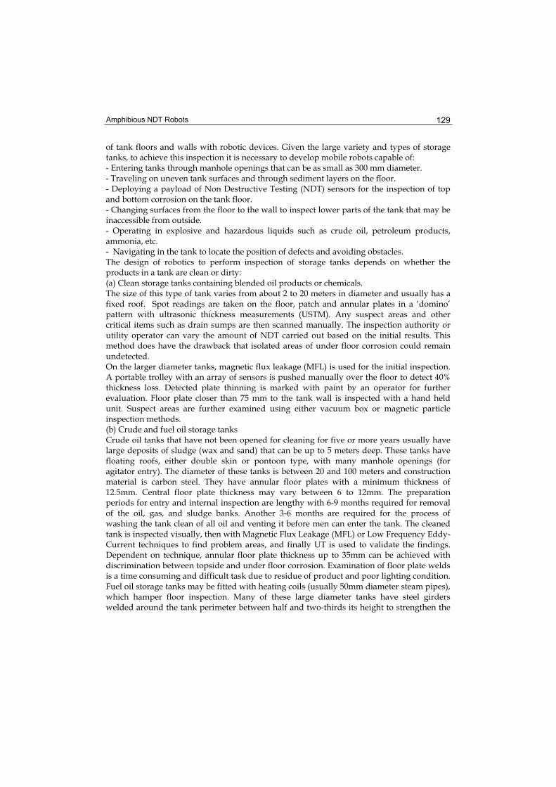
A second prototype vehicle has been developed (figures 3 - 6) that now has an additional mechanism. This comprises of an extendible arm and set of wheels to enable easier and more reliable surface changing capability. Two vehicle propellers provide sufficient thrust forces for adhesion to a wall with the shape of each propeller and associated flow duct engineered to increase the thrust. An array of ultrasonic wheel probes and two bulk-wave ROBULK probes look for corrosion thinning on the floor and walls up to half a meter ahead and under inaccessible floor areas. Sensor probes (4 immersion probes, 4 wheel probes and two rotating probes) are mounted on the vehicle chassis (see figures 4-5). The signal cables from these probes enter a water tight and pressurized chamber on the vehicle. Routing of these cables in a densely packed chamber is a problem. The rotating probe position is measured and controlled with shaft encoder feedback. Encoder signals are brought into the central chamber servo drive signals taken out to the two ROBULK probe motors.
Fig. 3. RobTank: Prototype 2 vehicle with a surface changing mechanism and two thrusters. The Central chamber houses all motors, encoders, servo drives and NDT instrumentation

Climbing & Walking Robots, Towards New Applications 134
Fig. 4. Underside mounting position for the array of ultrasonic (UT) probes
Fig. 5. Left: RobTank with full payload of 4 ultrasonic wheel probes, 4 compression probes and 2 rotating probes; Right: RobTank on the floor of a water storage tank, Sines oil refinery
Fig. 6. Left: RobTank before entry through manhole in the roof of a ATG storage tank, Sines oil refinery, Portugal; Right: Ultrasonic NDT tests in oil sludge

Amphibious NDT Robots 135
2.4.2 Module 2: NDT Probes and Instrumentation
The NDT sensor payload suitable for measuring internal and external corrosion with a thickness resolution of 1mm comprises of two probe arrays, each 30cm long with 15 to 20mm pitch, mounted to the front and rear of the inspection robot. The minimum detectable area is a 6mm diameter flat-bottomed hole at a range of 3 mm. A surface coverage of 3m2 per minute and surface speed of 10 m per minute is realizable with this arrangement. The inspection system is able to measure plate thickness between 6-25mm with minimum thickness of 3mm. One set of 0º (in the front of the vehicle, top of picture in figure 5) high efficiency twin wheel probes have been developed to cope with large crude oil tank inspection difficulties and environment conditions (penetration of debris and sludge on the tank floor). They are designed to European Standard EN10160 (July 1999) for the UT examination of steel planar plates. Tests on single and twin crystal probes scanning the surfaces of crude oil tank environments simulated in a laboratory showed a good ability to a cope with a range of conditions. This resulted in the development of a wheel probe system consisting of a high efficiency ultrasonic inspection twin wheel probe that obtains good data with a fluid gap or direct contact, ability to monitor wall thickness despite changes in probe orientation, size of probe, frequency of element and coverage, and the influence of sludge, sand and other tank constituents.
Fig. 7. Linear B Scan transformed to a Rotary B Scan to clarify tank features
Two long range ultrasonic probes that can look ahead through the floor are mounted on the sides of the inspection robot to detect hidden corrosion in areas that can only be reached with angled probes and not with 0º probes. These probes were developed after research

Climbing & Walking Robots, Towards New Applications 136
established that they will provide 100% coverage of large plate areas to give identification of potentially corroded areas in the plate with a look forward distance of 50 cm. Tests show that the range of the ROBULK ultrasonic probe is approximately 1m in water, proper calibration is essential, the probe is tolerant of small coupling gaps and will work through thin sand layers albeit with reduced range. The probe can be motorized and encoded to produce a radar type B scan plot to detect the edges of tanks, welds, etc and can therefore be used for navigation. The sound wave dives under unattached obstacles and can therefore inspect under striker plates. Figure 7 shows the wealth of information that can be obtained with a rotating bulk wave probe operated in a small water tank fitted with a drain outlet, welded stud and a weld in the floor. All these features are visible in figure 7 as is the weld between the tank floor and two walls with the corner visible. The waves travel up the walls of the tank and the top of the walls is also visible in the figure. A commercially available TD-Scan 24 channel flaw detector with dimensions of 170x60x104 mm is contained in the purged box on-board the robot. The TD-Scan instrument integrates a pulser/receiver, A/D converter, encoder inputs (the requirement is for one bi-directional input to describe forward/backward travel), and 2 unidirectional encoders to control the ROBULK probes). Software for data acquisition, display and analysis in all standard NDT formats is provided. The TD Pocket uses TTL signals from one of the robots incremental encoders to position stamp the NDT data.
2.4.3 Module 3: Navigation Sensors and Electronic Circuits
An Ultrasonic emitter Tower was mounted on top of the vehicle to simultaneously emit four ultra-sound signals to receivers mounted on the external wall of a tank. Each emitter is the hexamite “HE123 Underwater Ultrasonic Sensor”. A stack of three small electronics cards (overall dimensions of 100x100x60 mm) fire the ultrasonic emitters and process signals from the receivers. Four receivers on each face of the robot look out for reflections from obstacles in the tank. The system was unable to locate the robot in a large tank due to signals from reverberations of the walls caused by winds swamping the reflected ultrasonic signals and was eventually abandoned. An on-board Infrared camera and associated electronics is fixed to the front of the vehicle (overall size is 70x70x185 mm) with a coaxial cable relaying images to an external monitor. The final product will aim to meet all safety regulations for working in explosive atmospheres specified in API 653, API 575, Directive 94/9/EC (regulations CEN EN 1127-1:1997, CEN EN 50014:1997 and CENELEC EN 50284:1999) and Directive 1999/92/EC.
2.4.4 Laboratory and Field Trials
The fully assembled RobTank system was tested initially in laboratory water tanks and in two firefighting water tanks in a Petrogal refinery in Portugal. The fire fighting training tanks were used to assess the ability of the robot system to work on aged tank surfaces quite similar to the oil storage tanks in the refinery. The tanks were emptied, cleaned and a complete assessment and comparison of different inspection techniques carried out. The performance of the Rob Tank robot was compared with these results. Two major difficulties occurred at the laboratory trials stage, the solution of which resulted in significant delays to execution of the project plan. One difficulty related to the surface

Amphibious NDT Robots 137
changing ability of the vehicle. The addition of the NDT sensor payload changed the balance of the vehicle in addition to increasing its mass. The transition of the vehicle from the floor to a wall became erratic. As a result, a new mechanism was added to the front of the vehicle that comprised of a controlled buoyancy module (shown in figure 5 on top of the vehicle). This is activated before climbing a wall, thereby reducing the turning torques required to change surfaces. The second, more serious, difficulty was due to EMC problems caused by the PWM servo amplifiers used to control the propellers and wheel drive motors. The close proximity of parallel runs of NDT signal cables, PWM amplifiers and shaft encoder signals resulted in the swamping of low amplitude signals from the NDT sensors. A great deal of time was spent isolating the problems with redesign of probe cables, probe holders, screening, separation of flaw detector and amplifier grounds, and return of ground paths back from the vehicle through its umbilical to a ground on the operators end of things. Finally, RobTank was field tested in the Sines Oil refinery in Portugal. The vehicle performed as required in a badly corroded and buckled storage tank used for training in fire fighting. It was able to move reliably on the floor of the tank with a “light touch” with the two propellers turned off, and with more traction with the propellers rotating at full speed. Transfer from the floor onto very distorted tank walls was accomplished every time and the vehicle could easily climb to the level of liquid in the tank. Entry through a manhole on the roof of an AGT tank was easily performed by one operator without using any lifting equipment. The vehicle inspected the floor and walls of this tank without any major problems. The robot, at this stage in its development, has not sought certification for operation in explosive environments. Therefore it has not been tested in oil. However, the vehicle has been operated in a shallow bath filled with oil to test the NDT probes. These have given data comparable to the laboratory tests.
3. Design of Amphibious Swimming and Floor Moving Robot to Inspect Welds and Corrosion in FPSO Tanks
The RobTank design objectives have been extended further by developing an amphibious and mobile robotic inspection system to test welds located inside a floating production storage offloading tank (FPSO tank). FPSO tanks [Shimamura 2002] are storage tanks on ships that store oil off-loaded from off-shore platforms. Currently these welds are inspected manually by first emptying and cleaning the tank. This is a time consuming and expensive operation that requires operators to enter a hazardous environment.Significant cost reductions can be made if the inspection is performed with a robot that enters the tank when it is either nearly empty with two or three centimetres of oil remaining on the tank floor or preferably when it is of full of oil. In the first case the robot would operate in air and an explosive environment but would eliminate the need to swim the robot through a very complicated maze of partitioning walls and rows of strengthening plates that occur every 700-900 mm. In the second case the robot would swim to a strengthening plate and operate under oil thereby eliminating the need to empty the tank. The FPSO inspection task and suitable Non-destructive Testing methods are reported in (Sattar et al 2005; Sattar et al 2002). Figure 8 shows two FPSO tanks (lighter or yellow area)

Climbing & Walking Robots, Towards New Applications 138
in the cross-section of a ship hull. The strengthening plates are visible on the floor of each tank.
Fig. 8. Cross-section of the hull of a ship with two FPSO tanks, showing rows of strengthening plates welded between the floor and side walls
For structural safety the welds are tested regularly. The main inspection task is to test the welds on plates used to strengthen the walls and floor of the tank. Currently the welds are inspected manually after emptying the tank of product and thoroughly cleaning it. There is a large cost associated with the cleaning and inspection tasks. A pair of tanks are emptied, cleaned and inspected in 3-4 weeks with costs between £25-30K. A pair of FPSO tanks and ballast tanks inspected in the first five years costs £60-70k. This cost rises to £150-200k to inspect 3 pairs of cargo tanks and 3-4 pairs of ballast tanks after ten years. These costs can be reduced substantially by sending a robot into the tank without first emptying it thereby saving the cost of cleaning and emptying. Weld cracks are caused by fatigue and are of two types. Low-Cycle fatigue is driven by panel deflection when filling and emptying tanks causes cracks at the toe of a bracket, generally in the secondary material. High-Cycle fatigue is driven by wave pressure on the side and bottom shell of the tanks. It causes cracks at cut-outs where shell longitudinal strengthening plates connect to cut outs in the frames. The floor plate of the tank, usually 18-25mm thick, is tested for corrosion caused by coating breakdown. Pits can develop at the rate of 2-3 mm/year and even faster at the rate of 5mm/year if more corrosive crude is present.
3.1. The Inspection Environment
Obtaining access to welds on strengthening plates on the walls and the floors of the tank is not easy. The environment is cluttered with rows of strengthening plates that are 600-900 mm apart. The robot has to operate between two adjacent longitudinal strengthening plates separated by a distance of 600-900 mm with the transverse frames separated by a distance of 4.5m.The robot therefore has to be quite small, mass approximately 20kg, so that it can be inserted easily by one or at most two operators through a manhole of minimum diameter 600mm.Access to welds can be obtained by swimming over the plates from one section of the tank to another and then landing on a wall or floor between the plates.

Amphibious NDT Robots 139
3.2 Access to Floor Welds with a Swimming and Floor Moving Robot
FPSO Tanks in the North Sea are cleaned first with pressurized crude oil to agitate wax and sludge, and then cleaned with hot sea water. The water is removed prior to inspection by human operators, normally only a few centimeters are left on the bottom. The water in the tank tends to be fairly clean, though when disturbed can mix with the oil residues. Therefore, the inspection could be done by leaving the tank full of water and then gaining access to welds by swimming to a test site. Brazilian off-shore FPSO’s are not cleaned with hot water because they are operated in higher temperatures. Therefore, they are cleaned with pressurized oil only thus eliminating the cost of establishing a process that cleans the water before returning it to the sea. Here, a swimming robot would have to operate in crude oil and would therefore have to meet intrinsic safety requirements for operation in explosive environments. With zero visibility in crude oil, the problems of getting around the tank by swimming are considered to be insurmountable. However, emptying and cleaning the tank to the last few inches of oil on the floor and inspecting the welds with a robot still gives savings in costs and prevents human operators having to perform the NDT manually. Provided the cleaning systems are working, there is very little residue on the floor, though there is always a waxy film. In places there will be a 2-3mm of wax, like shoe polish on the bottom of the tank but not on the side walls.
3.3 NDT Techniques for FPSO Inspection
Work in tanks is always potentially hazardous and thus a system which can minimize the need for personnel entry is obviously beneficial. The development of a remote tool will only improve structural integrity, and thus potentially reduce leakage, if it can deliver a higher level of inspection than is currently achieved. The deck and bottom plating is normally 20-25mm thick. Bottom stiffeners are typically T-shaped with the web 650 x15mm, and the flange 250x25mm. Side shell stiffeners are generally bulb bars, 200-400wide and 12-15mm thick. Apart from butt joints joining plates together, all connections are fillet weld 6-10mm throat thickness depending on the section. Welding size is variable and depends on the design. Coating is provided by a paint layer 300-500 microns thick. The NDT is required to identify through thickness cracks that are 5-10mm long (these are currently generally found by visual inspection). If smaller cracks can be detected that would be bonus. It is also important to identify coating defects or pitting on the bottom plates. The project has developed an NDT Sensor Payload that is suitable for robotic deployment and that obtains better NDT data in a hazardous environment than possible with manual inspection. Towards this end, array probes have been developed to use the following NDT techniques: Eddy current technique, ultrasonic creep waves, and the ACFM (Alternating Current Field Measurement) technique. The Eddy Current Array technique is used to inspect the tank floor for corrosion pitting in the presence of sludge and wax. The robot carries a set of array probes and its motion results in a surface scan. A feasibility study with a conventional eddy current system shows that the conventional eddy current may work to pick up corrosion type of defect, if all the parameters are optimized. Therefore a system has been developed that consists of a conventional eddy current probe array.

Climbing & Walking Robots, Towards New Applications 140
ACFM (Alternating Current Field Measurement) techniques: ACFM is an electromagnetic inspection technique that provides one pass inspection. It has a high tolerance to lift off and requires no electrical contact so that it can be used to detect through coatings. It provides crack detection and sizing and is suitable for weld inspection. To cover the weld cap, toes and HAZ of a welded joint, it is necessary to either use a simple single sensor probe and scan several times or use a multisensor array probe and cover the required area in a single pass. An underwater ACFM array probe has been developed that can be deployed on the robotic vehicle. The probe detects and sizes surface breaking cracks at or in close proximity to the welds to be inspected. The probe design weighs approximately 1.2kg in air. The maximum dimensions are 87mm wide x 117mm long x 117mm high. The materials have been chosen to be mainly stainless steel for structural parts and PEEK for parts that will not be subject to great loads. Modifications still need to be made to make existing instrumentation intrinsically safe.
3.4 Design of Amphibious Mobile Robot
The design of the robot is shown in figures 9 and 10. This design is a further development of RobTank that has been developed for in-service inspection of oil and chemical storage tanks. Further development of this design has added a variable buoyancy tank that can quickly and accurately control buoyancy around the neutral buoyancy of the robot.
Fig. 9. Amphibious mobile robot showing the variable buoyancy tank on top of the sealed chamber housing the servo drive systems
The robot is designed to operate in air as well as submerged in water (at this stage) though eventually it will be made intrinsically safe to operate in crude oil (API 20 to 40). It consists of a buoyancy tank on top that adjusts its buoyancy around neutral by controlling its mass. A depth sensor provides the feedback to regulate the depth at which the robot is required to maintain its position (Shang et al 2006). All control systems are embedded on-board the robot in a gas pressurized central chamber sealed to prevent the ingress of water through any leaks at the rotating shafts emerging from the central chamber and through NDT sensor probe cables. The reason for placing most

Amphibious NDT Robots 141
hardware systems onboard the robot is to reduce the size of the umbilical cord so that cable management becomes easier.
Fig.10. Left: Swimming trials in 7meter deep tank; Right: Plan view of the robot showing location of ultrasonic range sensors and the six drive motors and two thruster motors
The outer dimensions of the robot are (mm): 410L x 300W x 300H. Its mass in air is 12 kg and it can carry a payload of 8kg. On-board embedded servo controllers with encoder feedback control the speed and position of the robot. High level control is from an operators console via RS 485 twin pair communications with on-board controllers. Both depth and horizontal motion is controlled simultaneously to swim the robot to a test site on a wall or above a floor area that is to be tested. After insertion of the robot through a manhole in the top deck, positive or negative buoyancy control is used to swim the robot vertically to a specified depth and to maintain that depth with neutral buoyancy. Two independent, speed controlled thrusters move the robot in a horizontal plane in the forward and reverse direction or rotate it to face in any direction. A system of four ultrasonic sensors operating at 10 KHz and a rotating ultrasonic sensor at 5 MHz profile the surrounding strengthening plates and tank walls. These sensors are used to align the robot and to guide it autonomously along welds between the floor and strengthening plates and the toe ends of the plates. The Cartesian scanner shown in figure 11 carrying an ACFM probe scans the welds after the robot has been positioned correctly. Robot trajectory in a constrained space for precise weld following around plates and side walls requires motion that is straight-line along welds, 90º rotation to present the scanner arm correctly when going from a plate to a side-wall and back onto the next plate. Special mechanisms have been designed to rotate all four wheels through turning angles between ± 180º and to independently control the speeds of all four wheels.

Climbing & Walking Robots, Towards New Applications 142
3.5 Scanning Arm
The robot is required to follow weld lines, stopping to deploy NDT probes with a scanning arm.
Fig. 11. Mechanical Scanner Design
Fig. 12. Scanner mounted on front face of robot, shown deploying an ACFM NDT probe while located between two stiffener plates in a FPSO tank
Figure 12 shows the robot with a scanning arm fitted to one of the faces. The robot is shown between two strengthening plates (stiffeners) and the side wall of a tank. The NDT sensor shown is an ACFM probe. The arm consists of two sets of 12mm diameter threaded shaft mechanisms, paired with guide shafts and their respective motor modules.

Amphibious NDT Robots 143
A horizontal threaded shaft and its dedicated motor module are mounted onto a back plate, which connects the scanner to the robotic platform. By setting the motor accordingly, the threaded shaft mechanism is able to provide the carriages with linear actuation along the X axis.The mechanical scanning arm designed to be used for carrying and deploying each NDT sensor at the desired location, is depicted in figure 11. The carriage itself comprises of a vertical shaft and a linear guide shaft jointed with articulated links to a linear guide actuator, which in turn is connected to the sensor holder that carries the sensor of each respective NDT method. The actuation provided by the motor module which is mounted onto the back plate, allows the carriage to move the threaded shaft and the guide shaft mechanism in opposite directions, thus moving inwards or outwards allowing actuation for the NDT sensor holder along the Z axis. Motion along the Y Axis is achieved by the actuation of the vertical threaded shaft. Finally, the linear actuator which is placed between the articulated links and the sensor holder drives the sensors along the X axis. The scanning arm’s modular configuration allows the sensor holder and thus the sensors to move along three degrees of freedom, so they can be placed safely and accurately into position in order to carry out the inspection of the welding. The retractable feature of the scanner arm contributes to the compact build of the overall system so it can be inserted easily into the inspection area and maintains its manoeuvrability by keeping the centre of mass close to the robot. When expanded, the sensor’s tip can reach up to 350mm in front of the robotic platform and with a linear guide actuator of 400mm in operational length, the sensor can inspect hardly accessible corners of the tank’s structure. The bearing load that the arm can hold may reach up to 4Kg , depending on the NDT method used at that time, which at this expanded position, will result to a required torque of 8Nm that the 24VDC motors are able to safely sustain. The linear displacement of each module is measured by the encoders which are embedded into the 24V DC motor arrangements. Due to the harsh environment under which the system is subjected to operate, delicate in construction components like the motor controller, motor drives and various custom electronics are shielded in to an IP69 enclosure inside the robotic platform’s casing. The linear guide actuator is composed of a one-piece outer rail surrounding an inner block, a ball screw drive through the block’s centre, and two linear motion guide raceways per each side of the block, that overall provide for a rigid actuator function and positional accuracy in the order of tenths of a millimetre. In order to avoid potential undesired contact with an object, the robot’s scanner must be able to map the space axially in front and on the side of the scanner. For the completion of this objective, 4 distance-measuring sensors are to be integrated on the sensor holder. The readings from these sensors as the scanner holder extends and retracts, will assist the robot’s overall behaviour while inspecting.
3.6 Following Motion Trajectories
The robot is required to follow strengthening plate welds by keeping the scanning arm parallel to a plate and rotating itself through ninety degrees after it has reached the tank wall. The space between two strengthening plate is very constrained so that large turning circles are not possible. The required trajectory is shown in figure 13.

Climbing & Walking Robots, Towards New Applications 144
Fig. 13. Robot trajectory between two adjacent strengthening plates
This trajectory is possible provided the four wheels can be turned through any angle between zero and ninety. A special mechanism actuated by two motors has been developed to permit this turning. Four mechanisms are required, one for each wheel. Two ultrasonic range finders are mounted on the front face of the robot. The scanning arm is mounted on this face.
Fig. 14. Sensor guided straight-line and rotational motion of robot to follow back-wall and plate welds
The trajectory that shows the principle of operation in figure 14 starts in position A. The robot can be rotated at the same position coordinates by turning all wheels to be at a pre-computed angle. The distance measured by each sensor is equalized by rotating anti/clockwise. The wheels are turned to face the wall as in position B and the robot moved towards the tank wall till it is at a required distance. The robot then moves along the wall towards the strengthening (stiffener) plate, maintaining the required distance, position C.

Amphibious NDT Robots 145
When the side range sensor detects the strengthening plate, the robot is rotated to face the plate, as shown in position D. The robot then aligns itself to be parallel and at a desired distance from the plate. The wheels are turned as in position E and the robot moves along the plate, inspecting the weld with the scanning arm.
3.7 Tests of Robot Motion when Operating in Air
The vehicle platform shown in figure 15 has been developed to test the motion of the robot when following a trajectory along stiffener welds.
Fig. 15. Left: Platform to test robot motion and trajectory following capability. Right: Fully assembled robot performing NDT on a mock-up with Creep waves
The mechanisms to rotate the robot at the same spot to find a stiffener or wall and then adjust the robot position to be normal to the wall have worked as expected. A limitation is the range of the ultrasonic sensors which work reliably up to 1.5 metres when the orientation angle of the robot is less than fifteen degrees. The robot is able to autonomously follow the weld along the stiffener plates and the side walls of the FPSO tank while maintaining the correct distance from the wall and stiffener plates.
3.8 Profiling Surrounding Plates with a Ultrasonic Radar
Experiments have been conducted to develop ultrasonic pulse echo radar that will enable the robot to detect the presence and distance of stiffener plates in a dark medium such as crude oil. This radar will be in addition to the four ultrasonic range finders mounted on the front and sides of the robot. The ultrasonic probe/mirror arrangement shown in figure 16 was rotated by ± 60º starting from the corner of two plates at right angles to each other. A C-scan image displays the detected plates and the corner where the two plates join. A grid of points was created where the probe was positioned.

Climbing & Walking Robots, Towards New Applications 146
Fig. 16. Ultrasonic radar probe setup to detect plates
An algorithm has been developed to compute plate distances from c-scan data. The distance of each plate from the 0,0 co-ordinate was x = 127.28 mm and y = 127.28 mm. Measurements were made by first looking at the corner and then rotating the table by ± 60º to measure the wall distances. The measured values for co-ordinate position 0,0 were x = 126.25 and y = 130.46, giving measurement errors of 1.03 and -2.18 mm respectively. Measurements were repeated with the probe at other grid points. The measurement errors were within ±4 mm, giving sufficient resolution to enable accurate profiling of the surrounding plates and other objects. Further work is being done to select a suitable probe frequency to give optimum results in oil and to develop the real-time computational algorithm to profile the objects and plates surrounding the robot
3.9 Results and Discussion
Figure 17 shows the A-scan results from the ultrasonic creep probe measurements with the defects at the beginning and end of the weld. In this experiment, an ultrasonic creep wave probe has been used to measure weld on a stiffener plate. The experimental setup is shown in figure 18. The creep wave probe consisting of dual crystal with an angle 24° at 4MHz was used. The choice of the frequency is related to the range of the inspection. Creep waves appear when the longitudinal wave is propagating at an angle greater than 75° but less than 90°. The optimum angle for a strong creep wave signal had to be determined within this range. In this application, the optimum value was found at a refracted angle of 80°. It has enough cover range to make it possible to inspect both fillet welds in the stiffener plate to the T-joint from the other side. Figure 17 also shows that the background noise is relatively high compared to the received signal.

Amphibious NDT Robots 147
Fig. 17. A-scan results from ultrasonic creep. (Position1) defect at the beginning of the weld and (Position 2) defect at the end of the weld
Fig. 18. Experimental setup for data collection using ACFM and ultrasonic creep wave probes
Due to this reason, determination of the defect size is difficult. The scan was then repeated using the ACFM probe. In the case of the ACFM sensor, a 50 kHz corrosion probe was used. The coils used to generate Eddy-current field in the test surface are placed either side of the test area. Their position will determine the direction of current flow, which must be across the cracks if the perturbations in the field are to be at a maximum. Sensor coils used in conventional eddy-current testing can be absolute (a simple single coil) or differential (a coil split into oppositely wound halves). In this experiment, the probe has a diameter of 50mm and provides Bx and Bz responses from defect depth. Bx and Bz corresponds to the field in the horizontal and vertical directions (Note: Bx is perpendicular to the current and parallel to the surface of the test sample, and the Bz is perpendicular to the surface of the test sample. For deployment on fatigue cracked weld toes for example where a crack is parallel to the weld, the x-direction will be parallel to the crack edge) Finally, since the sensitivity of the technique is also dependent on the area sensed by the coil, the smaller the area, the higher the sensitivity, the pairs of coils were arranged in arrays, that gave coverage of the whole weld surface.

Climbing & Walking Robots, Towards New Applications 148
Fig. 19. ACFM results: Scanning arm moves the probe – robot is parked
Fig. 20. ACFM results: Robot moves along the weld– arm is parked
Examples of the ACFM waveforms are shown in figures 19 and 20. These figures illustrate the Bx and Bz data of defects at the beginning and end of weld. Both ACFM and ultrasonic data are well correlated, indicating the position of the defects. Figure 19 shows results obtained by testing the weld with the robot parked and the scanning arm moving the ACFM probe along the weld. Figure 20 shows the test performed by keeping the arm stationary while moving the robot along the weld.Both methods were able to detect the defect indicating that provided the robot is able to keep a constant distance from the stiffener plates it may be enough to drag the probe over the weld.
Amphibious NDT Robots 149
4. Conclusion
Three prototype robots have been developed to gain entry into a large range of oil, petrochemical and process storage tanks. The robots are lightweight and compact so that they can be transported by one or two operators and easily inserted through the smallest manholes. The robots are amphibious, being able to operate in air and while submerged in liquids. They have been tested in water but the design incorporates the features to enable rapid progression to operation in oil and other flammable and explosive liquids. Between them, the robots can inspect: (a) The walls of storage tanks that may not be accessible from the outside due to rain plates and in partially or fully buried tanks. Wall inspection can be performed only when the tank is full of product. (b) The floors of storage tanks for corrosion and pitting by scanning the floor plates with ultrasonic compression probes, creep waves, and long range ultrasonic mapping of the floor area. This inspection can be performed in air or while submerged in liquids. (c) Welds by automatically following the weld seams along stiffener plates and wall plates while testing the weld using ACFM techniques with a scanning motion being performed by an arm. Raster motion trajectories can be easily achieved. This inspection can be performed in air or in liquids. (d) Tanks with constrained spaces and cluttered environments by swimming over obstacles to reach inspection target areas. The robots are prototypes that have demonstrated the feasibility of climbing, swimming and working on the floors of storage tanks in air and in water while performing NDT with a number of techniques. The designs have addressed the requirements for performing NDT in explosive environments but still have some way to go before they can be certified for operation in these tanks. Future work will aim to develop fully integrated systems that include the drive systems for the scanning arm in the sealed central chamber of the FPSO robot so that the intrinsic safety requirement of a single purged enclosure is achieved. The problem of a navigation system able to give sufficient information about the whereabouts of the robot in an opaque medium and closed steel tank is still not fully solved though local detection of the immediate surroundings and odometers give some knowledge. Never-the-less the robots can be operated in clean liquids where vision systems and operator line of sight is sufficient for teleoperation of the robots to a target area where the on-board sensors can take over and guide the robot through a pre-planned trajectory and inspection sequence.
5. Acknowledgements
This work was funded by the European Community through the CRAFT project FPSO INSPECT (COOP-2004-508599) [1] with the following partnership: NDT Consultant (UK), TSC Inspection Systems (UK), Isotest Engineering (Italy), Tecnitest Ingenieros (Spain), Spree Engineering Ltd (UK), Miltech Hellas S.A. (Greece), ZENON (Greece), Kingston Computer Consultancy (UK), BP (UK), Petrobras (Brazil) and London South Bank University (UK). The Project is coordinated and managed by TWI (UK). The Nueva Granada Military University of Colombia, sponsors the Ph.D studies of H.E. Leon Rodriguez.

Climbing & Walking Robots, Towards New Applications 150
The ACFM NDT results are the work of TWI Ltd, Cambridge (UK) and the results from experiments on ultrasonic radar are the work of Isotest Engineering, Italy. The work on RobTank Inspec was funded by the European Community through the FP6 programme (Competitive and sustainable growth). Project coordinator was ISQ Ltd (Portugal). Partners: Tecnatom (Spain), Phoenix Inspection Systems (UK), OIS (UK), London South Bank University (UK), Petrogal (Portugal).
6. References
Berger A., Knape B., Thompson B. (1990) Development of a Remote Tank Inspection (RTI) Robotic System, Proceedings of 1990 American Nuclear Society Winter Meeting,Washington D.C., November 1990
European CRAFT project FPSO-INSPECT, Non-Intrusive In-Service Inspection Robot for Condition Monitoring of Welds Inside Floating Production Storage and Off-loading (FPSO) Vessels, EU 6th Framework Programme, Co-operative Research Project, COOP-CT-2004-508599, December 2004.
King R.D., Raebiger, R.F., Friess R.A. (1992) Consolidated-Edison-Company-Of-New-York, Inc - Petroleum Fuel-Oil Tank Inspection Program, Proceedings of the American Power Conference, Chicago, Illinois, Vol 54, Pt 1 and 2 Moving Ahead While Protecting the Environment, pg. 983-988
Raad J.A. (1994) Techniques for Storage Tank Inspection, Materials Evaluation, July 1994, pg 806-7
Rusing, J.E. (1994) The NDT Perspective on Above Ground Storage Tanks, Materials Evaluation, July 1994, pg 801-804
(a) Sattar T.P., Leon-Rodriguez H., Shang J., (2005) Automated NDT Of Floating Production Storage Oil Tanks With A Swimming And Climbing Robot, in Proceedings of the 8th International Conference on Climbing and Walking Robots and the Support Technologies for Mobile Machines (CLAWAR 2005), Editors Tokhi, Virk and Hossain, ISBN-10 3-540-26413-2, Springer, ISBN-13 978-3-540-26413-2, pp. 935-942
(b) Sattar T.P., Zhao Z., Feng J., Bridge B., Mondal S., Chen S., (2002) Internal In-service Inspection of the floor and walls of Oil, Petroleum and Chemical Storage Tanks with a Mobile Robot, Proceedings Of 5th International Conference on Climbing and Walking Robots and the Support Technologies for Mobile Machines, Edited by Philipe Bidaud and Faiz Ben Amar, ISBN 1 86058 380 6, 2002, pp 947-954, Professional Engineering Publishing Ltd. UK
Schempf H. (1994). Neptune-Above-Ground Storage Inspection Robot System, Proceeding of IEEE International Conference on Robotics and Automation, San Diego, Vols 1-4, Part 2. pg. 1403-1408
Shang, J., Sattar, T.P., Leon Rodriguez , H.E, (2006) PDA Depth Control of a FPSO Swimming Robot, Proceedings of the 9th International Conference on Climbing and Walking Robots and the Support Technologies for Mobile Machines (CLAWAR 2006)
Shimamura Y. (2002) FPSO/FSO: State of the art, J. Mat. Sci. Technol. 2002, pp 60-70.

Climbing and Walking Robots: towards New ApplicationsEdited by Houxiang Zhang
ISBN 978-3-902613-16-5Hard cover, 546 pagesPublisher I-Tech Education and PublishingPublished online 01, October, 2007Published in print edition October, 2007
InTech EuropeUniversity Campus STeP Ri Slavka Krautzeka 83/A 51000 Rijeka, Croatia Phone: +385 (51) 770 447 Fax: +385 (51) 686 166www.intechopen.com
InTech ChinaUnit 405, Office Block, Hotel Equatorial Shanghai No.65, Yan An Road (West), Shanghai, 200040, China
Phone: +86-21-62489820 Fax: +86-21-62489821
With the advancement of technology, new exciting approaches enable us to render mobile robotic systemsmore versatile, robust and cost-efficient. Some researchers combine climbing and walking techniques with amodular approach, a reconfigurable approach, or a swarm approach to realize novel prototypes as flexiblemobile robotic platforms featuring all necessary locomotion capabilities. The purpose of this book is to providean overview of the latest wide-range achievements in climbing and walking robotic technology to researchers,scientists, and engineers throughout the world. Different aspects including control simulation, locomotionrealization, methodology, and system integration are presented from the scientific and from the technical pointof view. This book consists of two main parts, one dealing with walking robots, the second with climbing robots.The content is also grouped by theoretical research and applicative realization. Every chapter offers aconsiderable amount of interesting and useful information.
How to referenceIn order to correctly reference this scholarly work, feel free to copy and paste the following:
Tariq P. Sattar, Hernando E. Leon-Rodriguez and Jianzhong Shang (2007). Amphibious NDT Robots,Climbing and Walking Robots: towards New Applications, Houxiang Zhang (Ed.), ISBN: 978-3-902613-16-5,InTech, Available from:http://www.intechopen.com/books/climbing_and_walking_robots_towards_new_applications/amphibious_ndt_robots
![[PPT]Amphibious Warfare Training - United States · Web viewAgenda Amphibious Doctrine Organization of the Amphibious Task Force (Navy) Amphibious Ships Organization of the Landing](https://img.pdfslide.us/doc/110x75/5aa21ccb7f8b9ac67a8caf70/pptamphibious-warfare-training-united-states-viewagenda-amphibious-doctrine.jpg)