Embed Size (px)
Citation preview
821189: AMP1-16-M User Guide
© 2014 Wohler Technologies, Inc. Al l r ights reserved. i
AMP1-16-M
1RU, 16-Channel, 3G/HD/SD-SDI Audio Monitor
User Guide(Software Release: 4.0x)
Part Number 821189, Revision L
USO
RES
TRIT
O
821189: AMP1-16-M User Guide
© 2014 Wohler Technologies, Inc. Al l r ights reserved.ii
© 2014 Wohler Technologies, Inc. All rights reserved.
This publication is protected by federal copyright law. No part of this publication may be copied or distributed, stored in a retrieval system, or translated into any human or computer language in any form or by any means electronic, mechanical, manual, magnetic, or otherwise, or disclosed to third parties without the express written permission of Wohler Technologies.
Reproduction
Licensed users and authorized distributors of Wohler Technologies, Inc. products may copy this document for use with Wohler Technologies., Inc. products provided that the copyright notice above is included in all reproductions.
Customer Support
Wohler Technologies, Inc.31055 Huntwood AvenueHayward, CA 94544www.wohler.com
Phone: 510-870-0810FAX: 510-870-0811US Toll Free: 1-888-596-4537(1-888-5-WOHLER)Web: www.wohler.comSales: [email protected]: [email protected]
Disclaimers
Even though Wohler Technologies, Inc. has tested its equipment and software, and reviewed the documentation, Wohler Technologies, Inc. makes no warranty or representation, either express or implied, with respect to software, documentation, their quality, performance, merchantability, or fitness for a particular purpose.
In no event will Wohler Technologies, Inc. be liable for direct, indirect, special, incidental, or consequential damages resulting from any defect in the hardware, software, or its documentation, even if advised of the possibility of such damages.
Some states do not allow the exclusion or limitation for incidental or consequential damages, so the above exclusion or limitation may not apply to you.
Printing
This document is intended to be printed on a duplex printer, such that the copy appears on both sides of each page. This ensures that all new chapters start on a right-facing page.
This document looks best when printed on a color printer since some images may be indistinct when printed on a black and white printer.
All text strings appearing in this shade of blue are hyperlinks.
Other Technologies and Products
Microsoft Windows, and Internet Explorer are registered trademarks of Microsoft Corporation.
Last Update
April 9, 2014
USO
RES
TRIT
O
821189: AMP1-16-M User Guide
© 2014 Wohler Technologies, Inc. Al l r ights reserved. iii
Table of ContentsChapter 1. Quick Start. . . . . . . . . . . . . . . . . . . . . . . . . . . . .1
Introduction ...................................................................1
Overview..................................................................1
Topics ......................................................................1
Safety ...........................................................................2
Instructions ..............................................................2
Safety Symbols ........................................................3
Mounting..................................................................3
Heat Dissipation ........................................................3
Sympathetic Vibration ................................................3
Mechanical Bracing ....................................................4
Electrical Interference ................................................4
Power ......................................................................4
Compliance ....................................................................4
FCC .........................................................................4
IC-ECES-003 ............................................................5
Front Panel.....................................................................5
Rear Panel......................................................................7
Chapter 2. Operation. . . . . . . . . . . . . . . . . . . . . . . . . . . . . .9
Introduction ...................................................................9
Overview..................................................................9
Topics ......................................................................9
Main Screen .................................................................10
Trim Screen..................................................................12
USB Port Functionality ...................................................14
Copying a Configuration From the AMP1-16-M .............15
Copying a Configuration File from the AMP1-16-M........15
Update Menu ..........................................................16
USO
RES
TRIT
O
821189: AMP1-16-M User Guide
© 2014 Wohler Technologies, Inc. Al l r ights reserved.iv
Chapter 3. AMP1-16-M Graphical User Interface (GUI)
Manager . . . . . . . . . . . . . . . . . . . . . . . . . . . . . 17
Introduction..................................................................17
Overview................................................................17
Topics ....................................................................17
Running the AMP1-16-M Manager ....................................18
The SDI Setup Tabs .......................................................18
The Options Tab ............................................................19
The Ethernet Tab ...........................................................22
The USB Tab .................................................................24
Chapter 4. Internal Menu System. . . . . . . . . . . . . . . . . . . 27
Introduction..................................................................27
Overview................................................................27
Topics ....................................................................27
Menu Navigation Overview..............................................28
Audio Menu ..................................................................29
Trim Menu ....................................................................30
Channel Assignment Menu..............................................31
Options Menu................................................................32
Meter Type and Reference Menu ......................................34
Meter Segment Menu .....................................................37
Version and Ethernet Menu .............................................38
Chapter 5. Features and Specifications . . . . . . . . . . . . . . 41
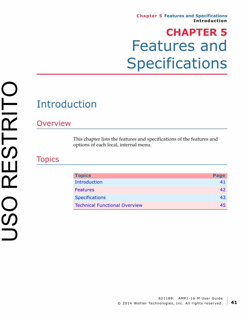
Introduction..................................................................41
Overview................................................................41
Topics ....................................................................41
Features.......................................................................42
Compliance...................................................................43
Specifications................................................................43
Audio Formats...............................................................44
USO
RES
TRIT
O
821189: AMP1-16-M User Guide
© 2014 Wohler Technologies, Inc. Al l r ights reserved. v
Technical Functional Overview.........................................45
Appendix A. Connecting the
AMP1-16-M to a LAN. . . . . . . . . . . . . . . . . . . .47
Introduction .................................................................47
Overview................................................................47
Topics ....................................................................47
Requirements ...............................................................48
Downloading the File .....................................................48
Installing the AMP1-16-M Manager .................................49
Launching the AMP1-16-M Manager .................................50
Adding Your AMP1-16-M to Your Network .........................51
Appendix B. Using a Direct Connection. . . . . . . . . . . . . . .55
Introduction .................................................................55
Overview................................................................55
Topic......................................................................55
Using a Direct Connection...............................................56
Appendix C. Upgrading the AMP1-16M using Ethernet . . .59
Introduction .................................................................59
Overview................................................................59
Topics ....................................................................59
Checking for Updates.....................................................60
Upgrading the AMP1-16-M..............................................62
Appendix D. Upgrading the AMP1-16-M Using a USB Flash
Drive . . . . . . . . . . . . . . . . . . . . . . . . . . . . . . . .63
Introduction .................................................................63
Overview................................................................63
Topic......................................................................63
Upgrading the Software Using a USB Flash Drive ...............64
USO
RES
TRIT
O

821189: AMP1-16-M User Guide
© 2014 Wohler Technologies, Inc. Al l r ights reserved.vi
U
SO R
ESTR
ITO
821189: AMP1-16-M User Guide
© 2014 Wohler Technologies, Inc. Al l r ights reserved 1
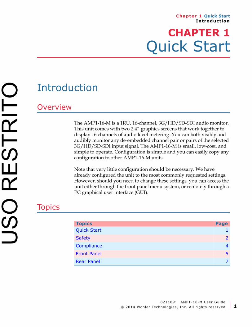
Chapter 1 Quick StartIntroduction
CHAPTER 1
Quick Start
Introduction
Overview
The AMP1-16-M is a 1RU, 16-channel, 3G/HD/SD-SDI audio monitor. This unit comes with two 2.4” graphics screens that work together to display 16 channels of audio level metering. You can both visibly and audibly monitor any de-embedded channel pair or pairs of the selected 3G/HD/SD-SDI input signal. The AMP1-16-M is small, low-cost, and simple to operate. Configuration is simple and you can easily copy any configuration to other AMP1-16-M units.
Note that very little configuration should be necessary. We have already configured the unit to the most commonly requested settings. However, should you need to change these settings, you can access the unit either through the front panel menu system, or remotely through a PC graphical user interface (GUI).
Topics
Topics Page
Quick Start 1
Safety 2
Compliance 4
Front Panel 5
Rear Panel 7
USO
RES
TRIT
O

821189: AMP1-16-M User Guide
© 2014 Wohler Technologies, Inc. Al l r ights reserved.2
Chapter 1 Quick StartSafety
Safety
Instructions
1. Read, keep, and follow all of these instructions; heed all warnings.
2. Do not use this equipment near water.
3. Use only a dry cloth to clean the equipment.
4. Do not block any ventilation openings.
5. Do not install near any heat source such as a radiator, heat register, amplifier, or stove.
6. Do not attempt to plug the unit into a two-blade outlet (with only two prongs of equal width).
7. Protect the power cord from being walked on or pinched, particularly at plug’s source on the equipment and at the socket.
8. Use only the attachments/accessories specified by the manufacturer.
9. Unplug the equipment during lightning storms or when unused for long periods of time.
10. Refer all servicing to qualified service personnel. Servicing will be required under all of the following conditions:
• The equipment has been damaged in any way, such as when the power-supply cord or plug is damaged.
• Liquid had been spilled or objects have fallen onto the equipment.
• The equipment has been exposed to rain or moisture.
• The equipment does not operate normally.
• The equipment has been dropped.
IMPORTANT: By design, this monitor will only plug into a three-prong outlet for your safety. If the plug does not fit into your outlet, contact an electrician to replace the obsolete outlet.
USO
RES
TRIT
O
821189: AMP1-16-M User Guide
© 2014 Wohler Technologies, Inc. Al l r ights reserved 3
Chapter 1 Quick StartSafety
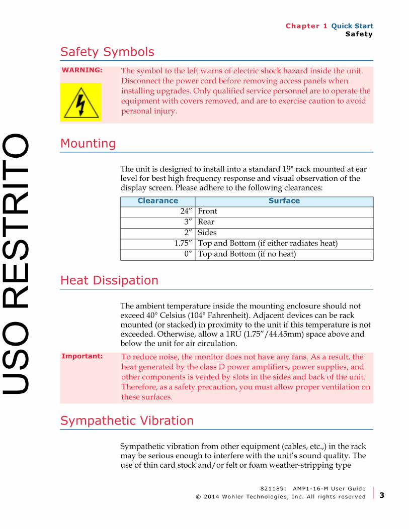
Safety Symbols
Mounting
The unit is designed to install into a standard 19" rack mounted at ear level for best high frequency response and visual observation of the display screen. Please adhere to the following clearances:
Heat Dissipation
The ambient temperature inside the mounting enclosure should not exceed 40° Celsius (104° Fahrenheit). Adjacent devices can be rack mounted (or stacked) in proximity to the unit if this temperature is not exceeded. Otherwise, allow a 1RU (1.75”/44.45mm) space above and below the unit for air circulation.
Sympathetic Vibration
Sympathetic vibration from other equipment (cables, etc.,) in the rack may be serious enough to interfere with the unit’s sound quality. The use of thin card stock and/or felt or foam weather-stripping type
WARNING: The symbol to the left warns of electric shock hazard inside the unit. Disconnect the power cord before removing access panels when installing upgrades. Only qualified service personnel are to operate the equipment with covers removed, and are to exercise caution to avoid personal injury.
Clearance Surface
24” Front
3” Rear
2” Sides
1.75” Top and Bottom (if either radiates heat)
0” Top and Bottom (if no heat)
Important: To reduce noise, the monitor does not have any fans. As a result, the heat generated by the class D power amplifiers, power supplies, and other components is vented by slots in the sides and back of the unit. Therefore, as a safety precaution, you must allow proper ventilation on these surfaces.U
SO R
ESTR
ITO
821189: AMP1-16-M User Guide
© 2014 Wohler Technologies, Inc. Al l r ights reserved.4
Chapter 1 Quick StartCompliance
materials between adjacent vibrating surfaces, or tying up loose cables, etc., may be required to stop vibrations external to the unit.
Mechanical Bracing
The 1RU chassis is securely attached to the front panel. In addition, the chassis has mounting tabs through which you attach it to the rack rail. This feature will reduce or eliminate rear bracing requirements in many mobile/portable applications. The weight of internal components is distributed fairly evenly around the unit.
Electrical Interference
Be careful to avoid mismatched cable types and other similar causes of undesired reflections in digital signal systems. If severe enough, such reflections can result in corruption of the digital data stream. As with any audio equipment, maximum immunity from electrical interference requires the use of shielded cable; however, satisfactory results can sometimes be obtained without it. The internal circuitry ground is connected to the chassis.
Power
The unit comes with a standard internal power supply and connects an A/C mains power source (60W, 100 to 240 VAC, ±10%, 50/60Hz) through the IEC connector provided on the rear panel of the unit.
When the mains plug or appliance coupler is used as the disconnect device, the disconnect device should remain operable.
Compliance
FCC
This equipment has been tested and found to comply with the limits for a Class A digital device, pursuant to part 15 of the FCC Rules. These limits are designed to provide reasonable protection against harmful interference when the equipment is operated in a commercial environment. This equipment generates, uses, and can radiate radio
USO
RES
TRIT
O
821189: AMP1-16-M User Guide
© 2014 Wohler Technologies, Inc. Al l r ights reserved 5
Chapter 1 Quick StartFront Panel
frequency energy and, if not installed and used in accordance with the instruction manual, may cause harmful interference to radio communications. Operation of this equipment in a residential area is likely to cause harmful interference in which case the user will be required to correct the interference at his own expense.
IC-ECES-003
This Class A digital apparatus complies with Canadian ICES-003.
Cet appareil numérique de la classe A est conforme à la norme NMB-003 du Canada.
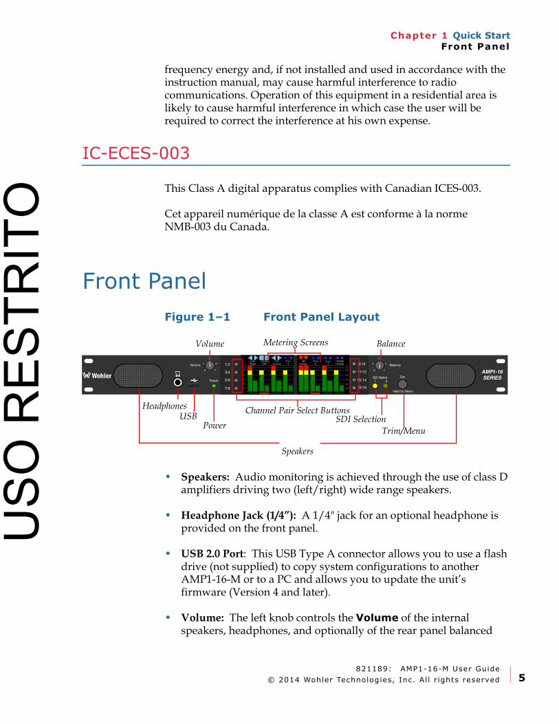
Front Panel
Figure 1–1 Front Panel Layout
• Speakers: Audio monitoring is achieved through the use of class D amplifiers driving two (left/right) wide range speakers.
• Headphone Jack (1/4”): A 1/4" jack for an optional headphone is provided on the front panel.
• USB 2.0 Port: This USB Type A connector allows you to use a flash drive (not supplied) to copy system configurations to another AMP1-16-M or to a PC and allows you to update the unit’s firmware (Version 4 and later).
• Volume: The left knob controls the Volume of the internal speakers, headphones, and optionally of the rear panel balanced
AMP1-16
SERIESWohler
15/16
1/2
3/4
5/6
7/8
9/10
11/12
13/14SDI Select1 2Power
BalanceVolume
Trim
0
-60
-50
-40
-30
-10-20
0
-60
-10-20
-30
-40
-50
Left /
Right
Center
LFE
L/R
S urrnd
B it
S tream
P air
4
P air
6P air
7
123456
123456
3 421 65 87 1211 1413 1615109
Hold for Menu
Speakers
Headphones
Volume Balance
Power
Channel Pair Select Buttons
Metering Screens
SDI SelectionUSB
Trim/Menu
USO
RES
TRIT
O
821189: AMP1-16-M User Guide
© 2014 Wohler Technologies, Inc. Al l r ights reserved.6
Chapter 1 Quick StartFront Panel
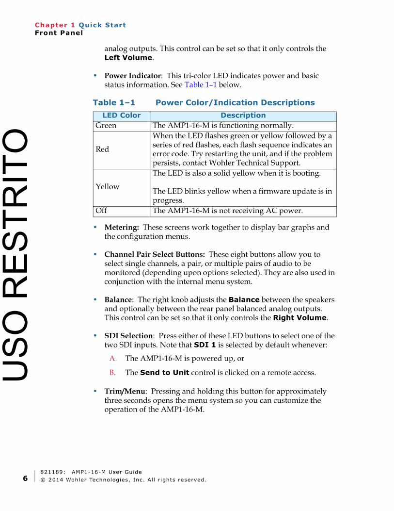
analog outputs. This control can be set so that it only controls the Left Volume.
• Power Indicator: This tri-color LED indicates power and basic status information. See Table 1–1 below.
• Metering: These screens work together to display bar graphs and the configuration menus.
• Channel Pair Select Buttons: These eight buttons allow you to select single channels, a pair, or multiple pairs of audio to be monitored (depending upon options selected). They are also used in conjunction with the internal menu system.
• Balance: The right knob adjusts the Balance between the speakers and optionally between the rear panel balanced analog outputs. This control can be set so that it only controls the Right Volume.
• SDI Selection: Press either of these LED buttons to select one of the two SDI inputs. Note that SDI 1 is selected by default whenever:
A. The AMP1-16-M is powered up, or
B. The Send to Unit control is clicked on a remote access.
• Trim/Menu: Pressing and holding this button for approximately three seconds opens the menu system so you can customize the operation of the AMP1-16-M.
Table 1–1 Power Color/Indication Descriptions
LED Color Description
Green The AMP1-16-M is functioning normally.
Red
When the LED flashes green or yellow followed by a series of red flashes, each flash sequence indicates an error code. Try restarting the unit, and if the problem persists, contact Wohler Technical Support.
Yellow
The LED is also a solid yellow when it is booting.
The LED blinks yellow when a firmware update is in progress.
Off The AMP1-16-M is not receiving AC power.
USO
RES
TRIT
O
821189: AMP1-16-M User Guide
© 2014 Wohler Technologies, Inc. Al l r ights reserved 7
Chapter 1 Quick StartRear Panel
Rear Panel
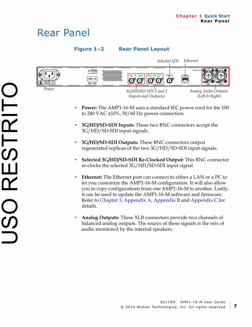
Figure 1–2 Rear Panel Layout
• Power: The AMP1-16-M uses a standard IEC power cord for the 100 to 240 VAC ±10%, 50/60 Hz power connection.
• 3G/HD/SD-SDI Inputs: These two BNC connectors accept the 3G/HD/SD-SDI input signals.
• 3G/HD/SD-SDI Outputs: These BNC connectors output regenerated replicas of the two 3G/HD/SD-SDI input signals.
• Selected 3G/HD/SD-SDI Re-Clocked Output: This BNC connector re-clocks the selected 3G/HD/SD-SDI input signal.
• Ethernet: The Ethernet port can connect to either a LAN or a PC to let you customize the AMP1-16-M configuration. It will also allow you to copy configurations from one AMP1-16-M to another. Lastly, it can be used to update the AMP1-16-M software and firmware. Refer to Chapter 3, Appendix A, Appendix B and Appendix C for details.
• Analog Outputs: These XLR connectors provide two channels of balanced analog outputs. The source of these signals is the mix of audio monitored by the internal speakers.
Power
Ethernet
3G/HD/SD-SDI 1 and 2 (Inputs and Outputs)
Analog Audio Outputs (Left & Right)
Selected SDI
USO
RES
TRIT
O

821189: AMP1-16-M User Guide
© 2014 Wohler Technologies, Inc. Al l r ights reserved.8
Chapter 1 Quick StartRear Panel
USO
RES
TRIT
O
821189: AMP1-16-M User Guide
© 2014 Wohler Technologies, Inc. Al l r ights reserved. 9
Chapter 2 OperationIntroduction
CHAPTER 2
Operation
Introduction
Overview
This chapter describes how to operate the AMP1-16-M.
Topics
Topics Page
Main Screen 10
Trim Screen 12
USB Port Functionality 14
USO
RES
TRIT
O
821189: AMP1-16-M User Guide
© 2014 Wohler Technologies, Inc. Al l r ights reserved.10
Chapter 2 OperationMain Screen
Main Screen
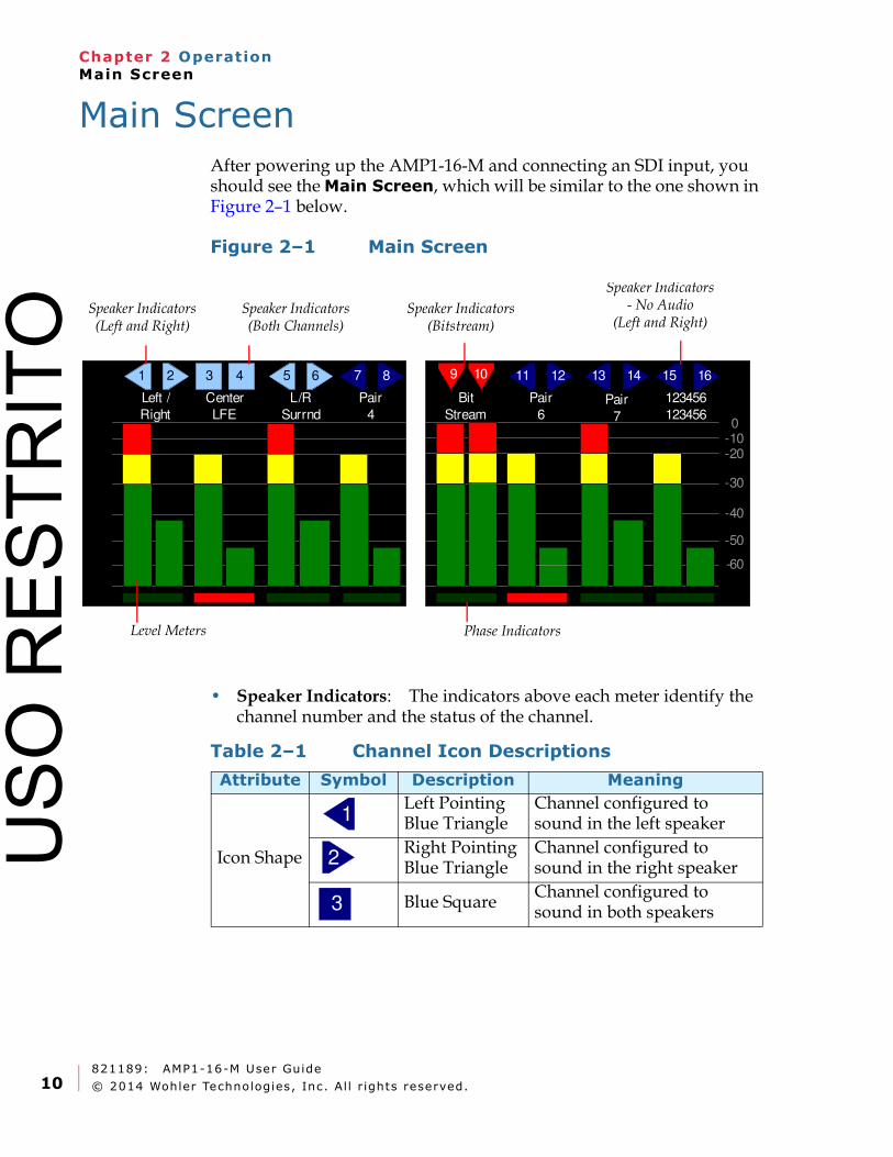
After powering up the AMP1-16-M and connecting an SDI input, you should see the Main Screen, which will be similar to the one shown in Figure 2–1 below.
Figure 2–1 Main Screen
• Speaker Indicators: The indicators above each meter identify the channel number and the status of the channel.
0
-60
-10-20
-30
-40
-50
Left /
Right
Center
LFE
L/R
Surrnd
Bit
Stream
Pair
4
Pair
6Pair
7
123456
123456
3 421 65 87 1211 1413 1615109
Speaker Indicators (Both Channels)
Speaker Indicators (Left and Right)
Speaker Indicators (Bitstream)
Speaker Indicators - No Audio
(Left and Right)
Phase IndicatorsLevel Meters
Table 2–1 Channel Icon Descriptions
Attribute Symbol Description Meaning
Icon Shape
Left Pointing Blue Triangle
Channel configured to sound in the left speaker
Right Pointing Blue Triangle
Channel configured to sound in the right speaker
Blue SquareChannel configured to sound in both speakers
1
2
3
USO
RES
TRIT
O
821189: AMP1-16-M User Guide
© 2014 Wohler Technologies, Inc. Al l r ights reserved. 11
Chapter 2 OperationMain Screen
• Level Meters: All of the channels are metered.
• Channel Selection: There are many ways to select channels for listening. There are two options located in the Meter Type and Reference Menu, which give four possible methods of selection. Regardless of the option settings, the icons in the main screen turn light blue to indicate the audio channel(s) selected will be summed to the speakers.
• Mono Channel Select - When set to Disable, both channels of a pair are quickly selected and deselected by repeated presses of a Channel Pair Select button. When set to Enable, multiple presses of a Channel Pair Select button will select or deselect one or both channels of the pair, allowing you to select individual channels. For example, using Pair Select 3/4:
o First press selects both channels for listening.
o Second press leaves only channel 3 selected.
o Third press leaves only channel 4 selected.
o Fourth press leaves both channels 3 and 4 deselected.
• Audio Pair Select – When set to Single, only one pair may be selected at any given time. Selecting any given pair will first deselect any other pairs. When set to Multiple, any number of pairs may be selected at one time for listening.
• Adjust the Volume and Balance controls as necessary.
The channel pairs can be given unique names. To do this, simply connect a PC to the Ethernet port and run the AMP1-16-M GUI setup program. Refer to Appendix A on page 47.
Icon Color
Light Blue Triangle or Square
Channel is selected by the Channel Pair Select buttons and can be heard
Dark Blue Triangle or Square
Channel is not selected by the Channel Pair Select buttons and cannot be heard
Downward Pointing Red Triangle
Channel contains a bitstream instead of audio and cannot be heard
Table 2–1 Channel Icon Descriptions (Continued)
Attribute Symbol Description Meaning
1
7
9
USO
RES
TRIT
O
821189: AMP1-16-M User Guide
© 2014 Wohler Technologies, Inc. Al l r ights reserved.12
Chapter 2 OperationTrim Screen
To select the channels that go to each speaker, either connect a PC to the Ethernet port or open the self-contained menu system. To enter or exit the menu system, hold the Trim button for three seconds or more. In the menus, whether internal or in the AMP1-16-M PC setup program, you can set many other operating characteristics of the AMP1-16-M to your exact needs. Refer to Chapter 3 on page 17.
• Phase Indicators: When any of these indicators are red, they indicate that the odd/even pair is out of phase. Green indicates in phase. Refer to Options Menu on page 32 for more information.
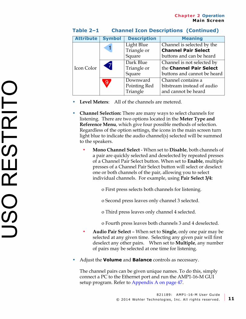
Trim Screen
Press the Trim control to switch between the Main Screen and the Trim Screen. The Trim Screen lets you to individually adjust the gain of each channel to monitor the audio either through the internal speakers or through the analog outputs. The Trim Screen is shown in Figure 2–2 below.
Figure 2–2 Trim Screen
The meters are labeled as they are in the Main Screen. At the bottom of each meter, a number indicates the amount of gain or loss being applied to each channel. If a gain is being applied, the number is indicated in a pink square. If a loss is being applied, the number is indicated in a green square. If no gain or loss is being applied, a zero is indicated in a white square. Adjacent to each meter, a small graphical indication appears, showing the gain or loss from +12 dB to -40 dB.
Left /
Right
Center
LFE
L/R
Surrnd
Bit
Stream
Pair
4
Pair
6Pair
7
123456
123456
3 4 65 87 1211 1413 1615
0 -10 -5 +12 +6 -10 -10 -5 +5-10 +5 -5 -50
21 109
M MUSO
RES
TRIT
O

821189: AMP1-16-M User Guide
© 2014 Wohler Technologies, Inc. Al l r ights reserved. 13
Chapter 2 OperationTrim Screen
You can adjust a channel pair by pressing one of the eight Channel Select buttons to highlight the icons at the top of the meters and then turning the Trim knob to increase or decrease the gain. If the gain is decreased below -40 dB, the channel is muted and an M is shown in a red square.
Multiple channel pairs can be adjusted simultaneously by first selecting each one and then turning the Trim knob to adjust. However, if Single channel pair selection is optioned as discussed in the previous section, then only one pair can be adjusted at a time.
You can adjust an individual channel by repeatedly pressing the Channel Select button until only the channel you want to adjust is highlighted. Then turn the Trim knob to adjust it.
The settings in the Audio Menu and Trim Menu determine the trimmed adjustments that affect the internal monitor speakers, the analog outputs, both, or neither. You can also disable access to the Trim Screen if necessary in the Trim Menu. Refer to the Audio Menu on page 29 and the Trim Menu on page 30.
When the levels of any channels have been trimmed, this flagged in the Main Screen to let you know that this has taken place. A red T in a white diamond shape is shown in the upper left of the screen. Refer to Figure 2–3.
Figure 2–3 Main Screen (Trim Adjusted)
0
-60
-10-20
-30
-40
-50
Left /
Right
Center
LFE
L/R
Surrnd
Bit
Stream
Pair
4
Pair
6Pair
7
123456
123456
3 421 65 87 1211 1413 1615109
USO
RES
TRIT
O
821189: AMP1-16-M User Guide
© 2014 Wohler Technologies, Inc. Al l r ights reserved.14
Chapter 2 OperationUSB Port Functionality
USB Port Functionality
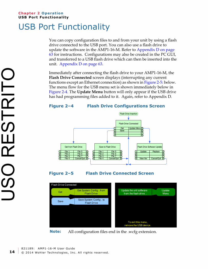
You can copy configuration files to and from your unit by using a flash drive connected to the USB port. You can also use a flash drive to update the software in the AMP1-16-M. Refer to Appendix D on page 63 for instructions. Configurations may also be created in the PC GUI, and transferred to a USB flash drive which can then be inserted into the unit. Appendix D on page 63.
Immediately after connecting the flash drive to your AMP1-16-M, the Flash Drive Connected screen displays (interrupting any current functions except an Ethernet connection) as shown in Figure 2-5: below. The menu flow for the USB menu set is shown immediately below in Figure 2-4. The Update Menu button will only appear if the USB drive has had programming files added to it. Again, refer to Appendix D.
Figure 2–4 Flash Drive Configurations Screen
Figure 2–5 Flash Drive Connected Screen
Flash Drive Connected
Get1Save2
34
56
Update Menu
78
Flash Drive Insertion
Save to Flash Drive
File 11File 22File 33File 44
File 7
5File 6 6File 5
7Cancel/Quit 8
Get from Flash Drive
File 11File 22File 33File 44
File 7
5File 6 6File 5
7Cancel/Quit 8
Flash Drive Software Update
Update123
View Ver4
56
Replace
7Cancel/Quit 8
Flash Drive Connected
Get System Config . from
Flash Drive
Save System Config . to
Flash Drive
To exit this menu ,
remove the USB device
Get
Save
Update the unit software
from the flash drive .
Update
Menu
Note: All configuration files end in the .wcfg extension.
USO
RES
TRIT
O
821189: AMP1-16-M User Guide
© 2014 Wohler Technologies, Inc. Al l r ights reserved. 15
Chapter 2 OperationUSB Port Functionality
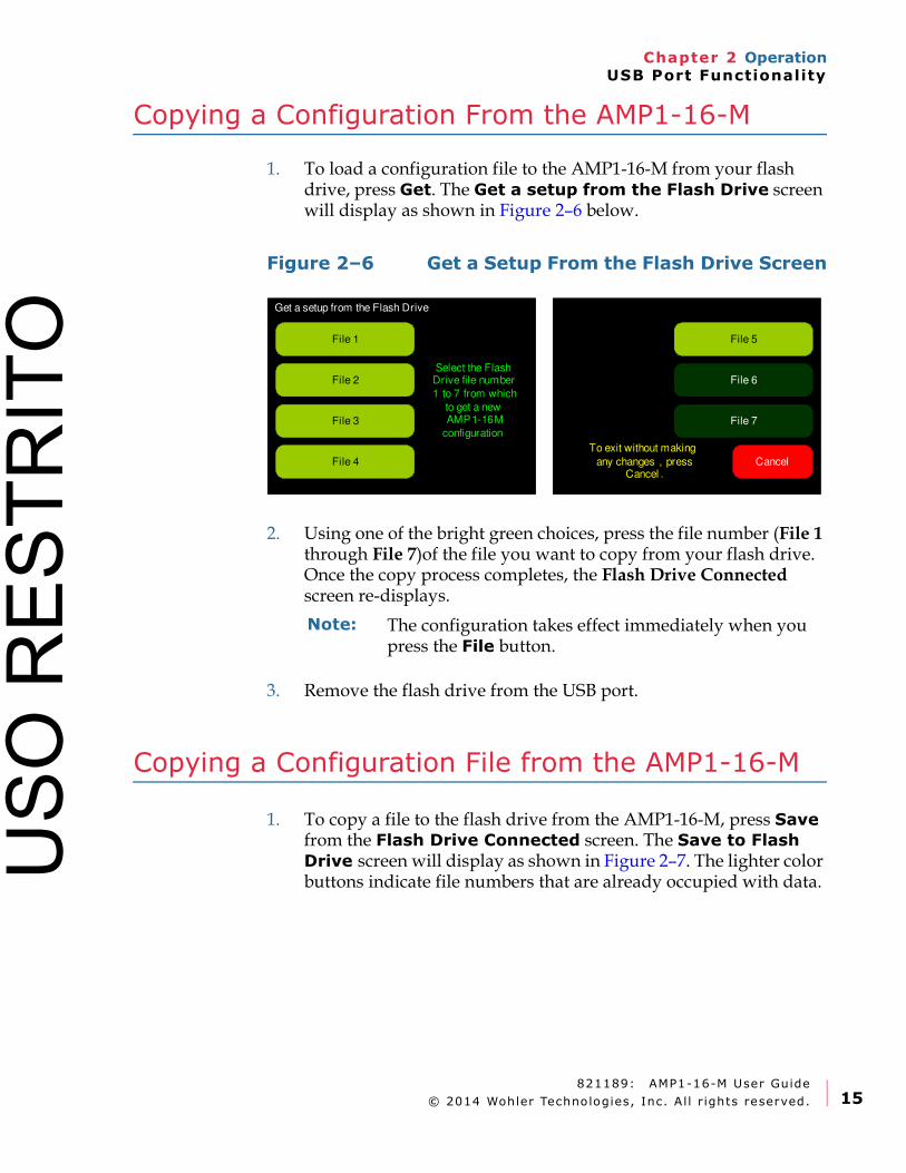
Copying a Configuration From the AMP1-16-M
1. To load a configuration file to the AMP1-16-M from your flash drive, press Get. The Get a setup from the Flash Drive screen will display as shown in Figure 2–6 below.
Figure 2–6 Get a Setup From the Flash Drive Screen
2. Using one of the bright green choices, press the file number (File 1 through File 7)of the file you want to copy from your flash drive. Once the copy process completes, the Flash Drive Connected screen re-displays.
3. Remove the flash drive from the USB port.
Copying a Configuration File from the AMP1-16-M
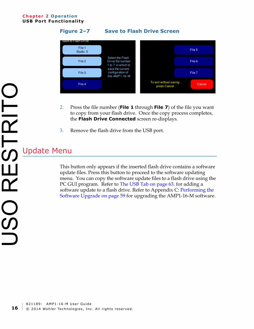
1. To copy a file to the flash drive from the AMP1-16-M, press Save from the Flash Drive Connected screen. The Save to Flash Drive screen will display as shown in Figure 2–7. The lighter color buttons indicate file numbers that are already occupied with data.
Get a setup from the Flash Drive
File 5
File 6
File 7
File 1
File 2
CancelFile 4
File 3
Select the Flash Drive file number
1 to 7 from which
to get a new AMP1-16M
configuration
To exit without making
any changes , press Cancel .
Note: The configuration takes effect immediately when you press the File button.
USO
RES
TRIT
O
821189: AMP1-16-M User Guide
© 2014 Wohler Technologies, Inc. Al l r ights reserved.16
Chapter 2 OperationUSB Port Functionality
Figure 2–7 Save to Flash Drive Screen
2. Press the file number (File 1 through File 7) of the file you want to copy from your flash drive. Once the copy process completes, the Flash Drive Connected screen re-displays.
3. Remove the flash drive from the USB port.
Update Menu
This button only appears if the inserted flash drive contains a software update files. Press this button to proceed to the software updating menu. You can copy the software update files to a flash drive using the PC GUI program. Refer to The USB Tab on page 63. for adding a software update to a flash drive. Refer to Appendix C: Performing the Software Upgrade on page 59 for upgrading the AMP1-16-M software.
Save to Flash Drive
File 5
File 6
File 7
File 1
Studio 5
File 2
CancelFile 4
File 3
Select the Flash Drive file number
1 to 7 in which to
save the current configuration of
this AMP1-16-M
To exit without saving ,
press Cancel .
USO
RES
TRIT
O

821189: AMP1-16-M User Guide
© 2014 Wohler Technologies, Inc. Al l r ights reserved. 17
Chapter 3 AMP1-16-M Graphical User Interface (GUI) ManagerIntroduction
CHAPTER 3
AMP1-16-M GraphicalUser Interface (GUI)
Manager
Introduction
Overview
This chapter describes how to use the AMP1-16-M Manager to the configure the AMP1-16-M.
Topics
Important: If you have not yet installed the AMP1-16-M Manager setup software into your PC and connected it to the AMP1-16-M, you must complete all the steps in Appendix A on page 47 before continuing.
Topics Page
Running the AMP1-16-M Manager 18
The SDI Setup Tabs 18
The Options Tab 19
The Ethernet Tab 22
The USB Tab 24
USO
RES
TRIT
O
821189: AMP1-16-M User Guide
© 2014 Wohler Technologies, Inc. Al l r ights reserved.18
Chapter 3 AMP1-16-M Graphical User Interface (GUI) ManagerRunning the AMP1-16-M Manager
Running the AMP1-16-M Manager
The AMP1-16-M Manager allows you to customize the monitor’s configuration to perfectly suit your needs.
The SDI Setup Tabs
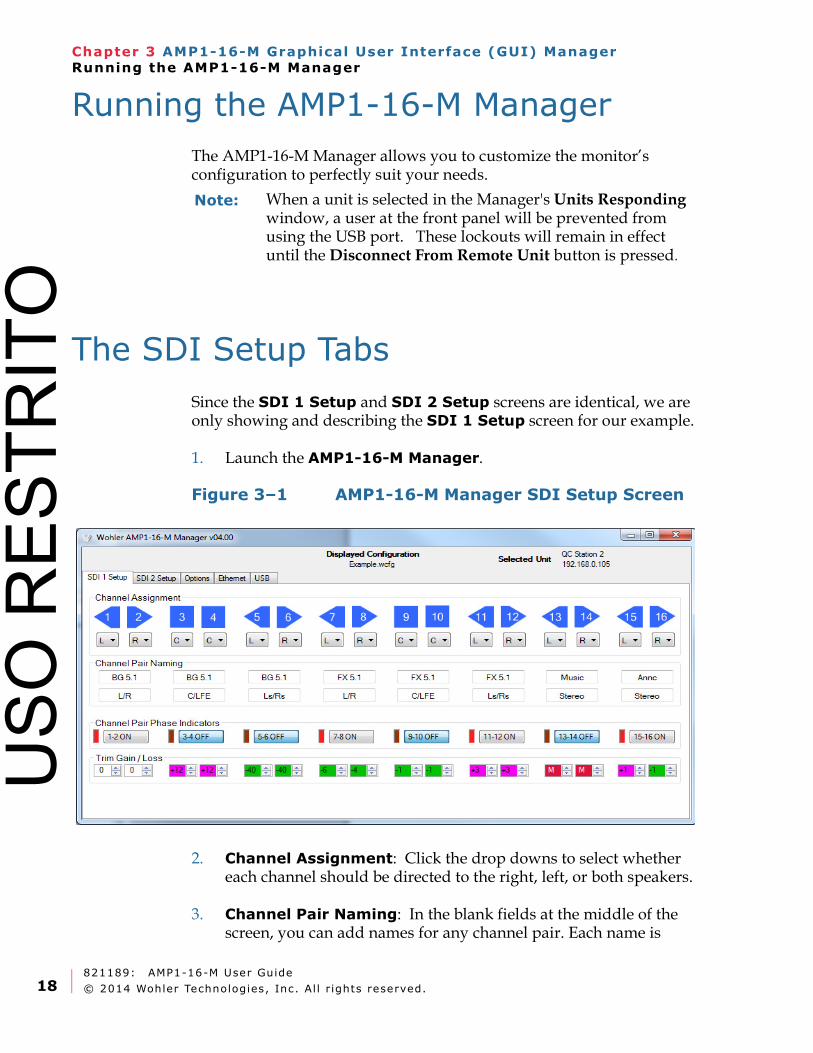
Since the SDI 1 Setup and SDI 2 Setup screens are identical, we are only showing and describing the SDI 1 Setup screen for our example.
1. Launch the AMP1-16-M Manager.
Figure 3–1 AMP1-16-M Manager SDI Setup Screen
2. Channel Assignment: Click the drop downs to select whether each channel should be directed to the right, left, or both speakers.
3. Channel Pair Naming: In the blank fields at the middle of the screen, you can add names for any channel pair. Each name is
Note: When a unit is selected in the Manager's Units Responding window, a user at the front panel will be prevented from using the USB port. These lockouts will remain in effect until the Disconnect From Remote Unit button is pressed.
USO
RES
TRIT
O
821189: AMP1-16-M User Guide
© 2014 Wohler Technologies, Inc. Al l r ights reserved. 19
Chapter 3 AMP1-16-M Graphical User Interface (GUI) ManagerThe Options Tab
comprised of the top and bottom field, and each field allows up to seven characters.
4. Channel Pair Phase Indicators: For each channel pair, click the button to toggle the phase indication on or off.
5. Trim Gain/Loss: Click the up or down arrows beside each Trim/Gain Loss value to either increase or decrease the gain or loss.
6. When you’re done with this screen, click the SDI 2 Setup screen and repeat Steps 2 through 5 above for the second SDI input.
The Options Tab
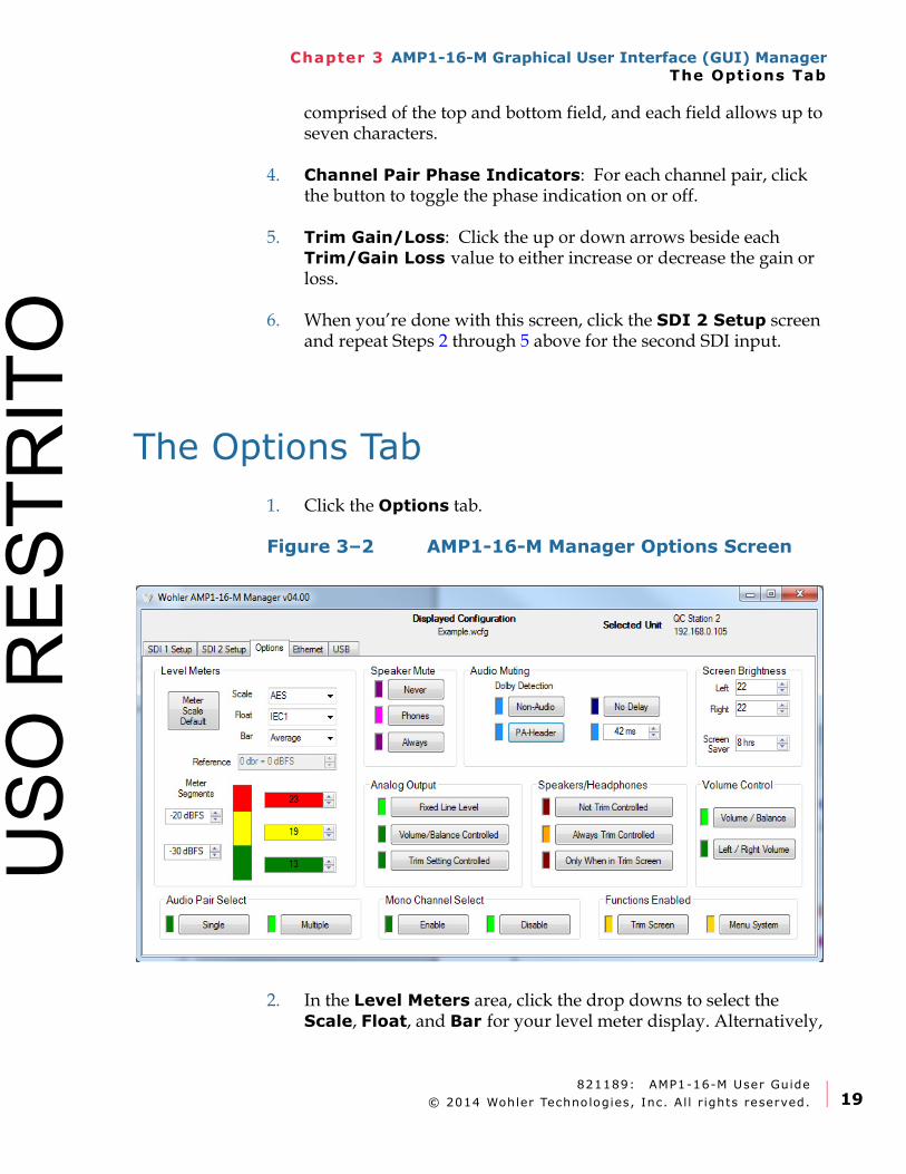
1. Click the Options tab.
Figure 3–2 AMP1-16-M Manager Options Screen
2. In the Level Meters area, click the drop downs to select the Scale, Float, and Bar for your level meter display. Alternatively,
USO
RES
TRIT
O
821189: AMP1-16-M User Guide
© 2014 Wohler Technologies, Inc. Al l r ights reserved.20
Chapter 3 AMP1-16-M Graphical User Interface (GUI) ManagerThe Options Tab
you can click the Meter Scale Default button to return to the default for that scale. The scale itself won't change.
3. Also in the Level Meters area, click the up or down arrows to select the levels at which the colors between the top and middle segments and the middle and lower segments.
4. Click the up or down arrows to select the colors for each of the level meter segments.
5. In the Speaker Mute area, click to select one of three speaker configurations:
A. Never: Never mute the speakers even when headphones are connected.
B. Phones: Only mute the speakers when the headphones are connected.
C. Always: Always keep the speakers muted. This option may be useful if you only want to monitor audio externally, through the XLR audio outputs on the rear panel.
6. In the Analog Output area, click to select one of three output volume options. Fixed Line Level is exclusive of the other two:
A. Fixed Line Level: The volume of the output is fixed to the volume of the corresponding inputs.
B. Volume/Balanced Controlled: The volume of the outputs is controlled by the Volume and Balance knobs on the front panel.
C. Trim Controlled: The analog outputs are controlled by the Trim settings.
7. In the Audio Muting and Delay area select any combination of Non-Audio or PA Header.
Note: Note, if the Analog Output is set to controlled and the Speaker Mute is set to Always, then plugging in the headphones will cause the analog outputs to mute.
Note: The AMP1-16-M detects PA headers that represent encoded data streams.
USO
RES
TRIT
O
821189: AMP1-16-M User Guide
© 2014 Wohler Technologies, Inc. Al l r ights reserved. 21
Chapter 3 AMP1-16-M Graphical User Interface (GUI) ManagerThe Options Tab
8. For the Delay, click either No Delay, or click the up or down arrows to either increase or decrease the amount of audio delay time.
9. In the Speakers/Headphones area, click either Not Trim Controlled to eliminate trim control altogether, Always Trim Controlled to enable trim control in both the Trim Screen and the Monitoring Screen, or Only When in Trim Screen to enable trim control only in the Trim Screen.
10. In the Volume Control area, select the way the Volume and Balance knobs should operate:
A. Volume/Balance: This setting selects normal Volume and Balance control operation as labeled on the front panel. This is the default.
B. Left/Right Volume: This setting reconfigures the Volume control to work as a left volume control and the Balance control to work as a right volume control.
11. In the Screen Brightness area, the select the screen brightness for each screen and the duration for the screen saver.
A. Left/Right: Either click the down arrow to increase or decrease the screen brightness value, or click the field and type in a value.
B. Screen Saver: Enter the amount of time you want the monitor to wait until it invokes the screen saver. Allowable values range in 1 minute increments from 5 minutes to 119 minutes, and in 1 hour increments from 2 hours to 24 hours. The default setting is 8 hours. If the AMP1-16-M is in operation for the screen saver time-out period and no front panel controls have been turned or pressed, the screens will dim by a certain amount. If double the screen saver time-out period elapses without any front panel control activity, the screens will dim further. Operating any button or control will instantly brighten the screens.
12. In the Functions Enabled area, click Trim Screen to enable the Trim Screen and/or the Menu System to enable the menu system.
USO
RES
TRIT
O
821189: AMP1-16-M User Guide
© 2014 Wohler Technologies, Inc. Al l r ights reserved.22
Chapter 3 AMP1-16-M Graphical User Interface (GUI) ManagerThe Ethernet Tab
13. Audio Pair Select and Mono Channel Select: These two options control the method of channel selection on the main screen of the unit.
• Mono Channel Select – When set to Disable, both channels of a pair are quickly selected and deselected by repeated presses of a Channel Pair Select button. When set to Enable, multiple presses of a Channel Pair Select button will select or deselect one or both channels of the pair, allowing you to select individual channels. For example, using Pair Select 3/4:
o First press selects both channels for listening.
o Second press leaves only channel 3 selected.
o Third press leaves only channel 4 selected.
o Fourth press leaves both channels 3 and 4 deselected.
• Audio Pair Select – When set to Single, only one pair may be selected at any given time. Selecting any given pair will first deselect any other pairs. When set to Multiple, any number of pairs may be selected at one time for listening.
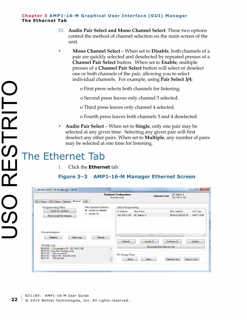
The Ethernet Tab1. Click the Ethernet tab.
Figure 3–3 AMP1-16-M Manager Ethernet Screen
USO
RES
TRIT
O
821189: AMP1-16-M User Guide
© 2014 Wohler Technologies, Inc. Al l r ights reserved. 23
Chapter 3 AMP1-16-M Graphical User Interface (GUI) ManagerThe Ethernet Tab
The Ethernet tab allows you to transmit configurations and perform a variety of other tasks over a network.
• Programming Files—Check for Updates: Clicking this button checks the Wohler FTP site for updated software. Note: If Update All is checked, all the files on the local computer will be updated, regardless of whether or not they are current.
• Programming Files—Show Local File Versions: Clicking this button displays the current versions of all the software components stored on the host computer; and, if a unit is selected in the Units Responding window, the versions of software stored in the unit itself.
• File Update Options: Before beginning any update procedure, click either Update as Needed or Update All. Update as Needed should be used for most updates. Update All should only be used at the direction of a tech support representative.
• Documentation—Readme: Clicking this button displays the readme.txt file for the downloaded software updates, which includes a list of feature changes and fixes for each version released to-date.
• Documentation—Open Log: Clicking this button opens the contents of the Activity Log in Notepad of Wordpad so that you may save the log to a desired location. Log files are automatically saved in the C:/Wohler/AMP1-16-M/User folder.
• Documentation—Manual: Clicking this button allows you to read this document in .pdf format.
• Activity Log: The Activity Log area displays system response data to the various functions on this menu.
Note: For a complete description of the functions in the Units Responding area refer to Appendix A on page 47.
For a complete description of the functions in the Programming Files area (used to attach AMP1-16-Ms to a network) refer to Appendix C on page 59
Note: This controls both the unit update function and the Check for Updates function. If you wish to perform a software update now, proceed to Appendix A on page 47.
USO
RES
TRIT
O
821189: AMP1-16-M User Guide
© 2014 Wohler Technologies, Inc. Al l r ights reserved.24
Chapter 3 AMP1-16-M Graphical User Interface (GUI) ManagerThe USB Tab
To perform any of the following functions, you must have an AMP1-16-M selected in the Units Responding box.
• Get from Unit: Clicking the Get from Unit button transmits the configuration file from the AMP1-16-M that you selected on the Units Responding box to the PC.
• Save: Clicking the Save button allows you save an AMP1-16-M configuration file to the PC.
• Open: Clicking the Open button allows you to select an AMP1-16-M configuration from those saved on your PC.
• Send to Unit: Clicking the Send to Unit button allows you to transfer an AMP1-16-M configuration file from your PC to the AMP1-16-M that is selected in the Units Responding box.
• Disconnect from Remote Unit: Click this button to disconnect from the remote unit. The front-panel USB functions and menu system will be unlocked.
The USB Tab
You can copy up to seven configuration files to or from a USB flash drive connected to your computer. You can then use this USB flash drive to copy those settings into an AMP1-16-M using the front-panel USB connector.
When one or more flash drives are connected to the computer, they will be shown in the Drive list box, and any settings files found on the selected rive will be shown in the Flash Drive Files window.
Note: The button descriptions below are not listed in the order that they appear on the Ethernet tab. Instead, they are listed in the most likely order that you would use them.
Note: To use the USB port from the AMP1-16-M menu system, refer to USB Port Functionality on page 14.U
SO R
ESTR
ITO
821189: AMP1-16-M User Guide
© 2014 Wohler Technologies, Inc. Al l r ights reserved. 25
Chapter 3 AMP1-16-M Graphical User Interface (GUI) ManagerThe USB Tab
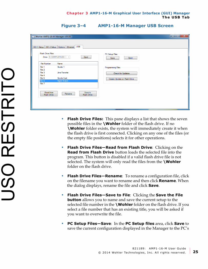
Figure 3–4 AMP1-16-M Manager USB Screen
• Flash Drive Files: This pane displays a list that shows the seven possible files in the \Wohler folder of the flash drive. If no \Wohler folder exists, the system will immediately create it when the flash drive is first connected. Clicking on any one of the files (or the empty file positions) selects it for other operations.
• Flash Drive Files—Read from Flash Drive: Clicking on the Read from Flash Drive button loads the selected file into the program. This button is disabled if a valid flash drive file is not selected. The system will only read the files from the \Wohler folder on the flash drive.
• Flash Drive Files—Rename: To rename a configuration file, click on the filename you want to rename and then click Rename. When the dialog displays, rename the file and click Save.
• Flash Drive Files—Save to File: Clicking the Save the File button allows you to name and save the current setup to the selected file number in the \Wohler folder on the flash drive. If you select a file number that has an existing title, you will be asked if you want to overwrite the file.
• PC Setup Files—Save: In the PC Setup files area, click Save to save the current configuration displayed in the Manager to the PC’s
USO
RES
TRIT
O
821189: AMP1-16-M User Guide
© 2014 Wohler Technologies, Inc. Al l r ights reserved.26
Chapter 3 AMP1-16-M Graphical User Interface (GUI) ManagerThe USB Tab
hard drive. When the Save As dialog appears, browse to the folder where you wish to save the file, and then click Save.
• PC Setup Files—Open: In the FPC Setup Files area, click Open to open a file from the PC’s hard drive. The Open dialog will appear where you can browse to the desired configuration file. When you press Open, this will become the current configuration displayed in the Manager.
Programming Files—This pane relates to preparing a flash drive to be used to update the software in AMP1-16-M units.
• Check for Updates: Clicking on this button checks the Wohler website for updated software, and if it exists, it downloads it.
• Create Update on Flash Drive: Whether a new update was available on the Wohler website or not, this button can be used to create a software update on the attached USB flash drive. After this operation is performed, AMP1-16-M units will recognize that an update is available on the flash drive and will offer to update themselves from it.
• Note: Units with versions prior to 4.00 will not perform a software update from a USB stick. This must be done using the Ethernet port.
Note: This button has the exact same functionality as the Save button on the Ethernet tab. It is repeated here for your convenience.
Note: This button has the exact same functionality as the Open button on the Ethernet tab. It is repeated here for your convenience.
USO
RES
TRIT
O
821189: AMP1-16-M User Guide
© 2014 Wohler Technologies, Inc. Al l r ights reserved. 27
Chapter 4 Internal Menu SystemIntroduction
CHAPTER 4
Internal Menu System
Introduction
Overview
This chapter provides an in-depth description of all the features, specifications, and menus and all their respective options and functions. Note that the menus are listed alphabetically for easy reference.
Topics
Important: The AMP1-16-M local menus cannot be used at the same time that the PC setup software is connected. If this happens, the PC Setup Software will take precedence and display a yellow diamond notifying you about the PC connection. When the PC access is finished, the yellow diamond will disappear, once again enabling local menu access.
Topics Page
Menu Navigation Overview 28
Audio Menu 29
Trim Menu 30
Channel Assignment Menu 31
Options Menu 32
Meter Type and Reference Menu 34
Meter Segment Menu 37
Version and Ethernet Menu 38
USO
RES
TRIT
O
821189: AMP1-16-M User Guide
© 2014 Wohler Technologies, Inc. Al l r ights reserved.28
Chapter 4 Internal Menu SystemMenu Navigation Overview
Menu Navigation Overview
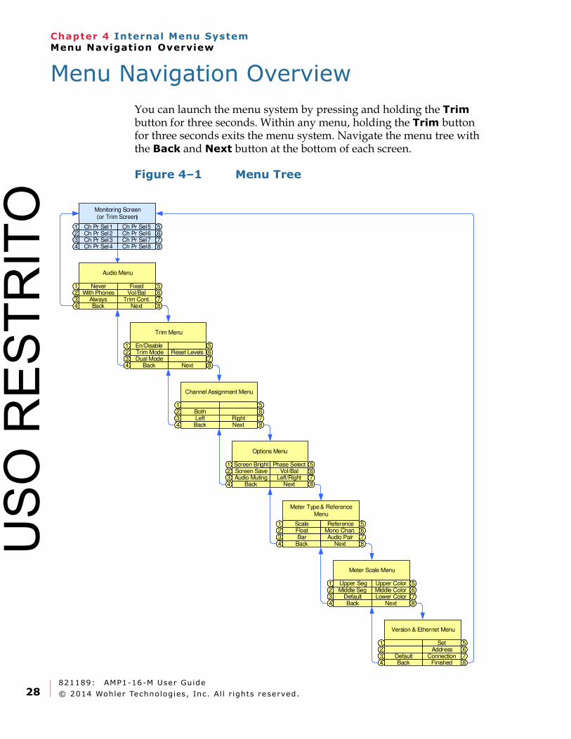
You can launch the menu system by pressing and holding the Trim button for three seconds. Within any menu, holding the Trim button for three seconds exits the menu system. Navigate the menu tree with the Back and Next button at the bottom of each screen.
Figure 4–1 Menu Tree
Monitoring Screen (or Trim Screen)
Ch Pr Sel 11Ch Pr Sel 22Ch Pr Sel 33Ch Pr Sel 44
Ch Pr Sel 5 5Ch Pr Sel 6 6Ch Pr Sel 7 7Ch Pr Sel 8 8
Audio Menu
Never1With Phones2
Always3Back4
Vol/Bal5
Trim Cont.6
Fixed
7Next 8
Trim Menu
En/Disable1Trim Mode2Dual Mode3
Back4
Reset Levels567
Next 8
Version & Ethernet Menu
12
Default3Back4
Set 5Address 6
Connection 7Finished 8
Meter Scale Menu
Upper Seg1Middle Seg2
Default34
Upper Color 5Middle Color 6Lower Color 7
Next 8Back
Meter Type & Reference Menu
Scale1Float2Bar3
Back4
Reference 5Mono Chan. 6Audio Pair 7
Next 8
Channel Assignment Menu
1Both2Left3Back4
56
Right 7Next 8
Options Menu
Screen Save1 Screen Bright2
Audio Muting3Back4
Phase Select 5Vol/Bal 6
Left/Right 7Next 8
USO
RES
TRIT
O
821189: AMP1-16-M User Guide
© 2014 Wohler Technologies, Inc. Al l r ights reserved. 29
Chapter 4 Internal Menu SystemAudio Menu
• Back: Pressing this button closes this menu and opens the previous menu, one step up the menu tree.
• Next: Pressing this button closes this menu and opens the next menu, one step down the menu tree.
Audio Menu
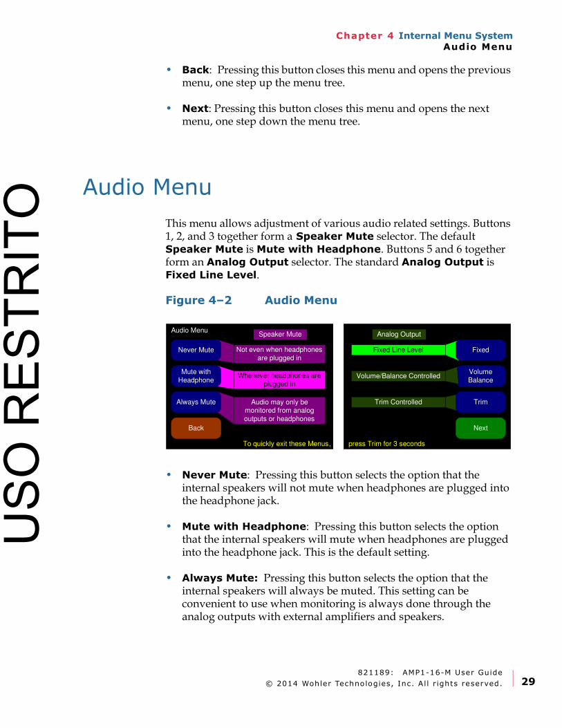
This menu allows adjustment of various audio related settings. Buttons 1, 2, and 3 together form a Speaker Mute selector. The default Speaker Mute is Mute with Headphone. Buttons 5 and 6 together form an Analog Output selector. The standard Analog Output is Fixed Line Level.
Figure 4–2 Audio Menu
• Never Mute: Pressing this button selects the option that the internal speakers will not mute when headphones are plugged into the headphone jack.
• Mute with Headphone: Pressing this button selects the option that the internal speakers will mute when headphones are plugged into the headphone jack. This is the default setting.
• Always Mute: Pressing this button selects the option that the internal speakers will always be muted. This setting can be convenient to use when monitoring is always done through the analog outputs with external amplifiers and speakers.
Audio MenuAnalog Output
Volume/Balance ControlledVolume
Balance
Trim
Not even when headphones
are plugged in
Whenever headphones are
plugged in
Never Mute
Mute with
Headphone
NextBack
Fixed Line Level
Speaker Mute
Audio may only be monitored from analog
outputs or headphones
Always Mute
To quickly exit these Menus, press Trim for 3 seconds
Fixed
Trim Controlled
USO
RES
TRIT
O
821189: AMP1-16-M User Guide
© 2014 Wohler Technologies, Inc. Al l r ights reserved.30
Chapter 4 Internal Menu SystemTrim Menu
• Fixed: Pressing this button fixes the line level of the analog outputs as they are in the SDI signal, where -20 dBFS = +4 dBu (± 1 dB). This is the default setting.
• Volume/Balance: Pressing this button enables the Volume and Balance controls to affect the analog outputs. This setting can be convenient to use when monitoring is always done through the analog outputs with external amplifiers and speakers.
• Trim: Pressing this button enables the Trim controls to affect the analog outputs.
Trim Menu
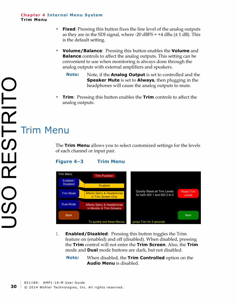
The Trim Menu allows you to select customized settings for the levels of each channel or input pair.
Figure 4–3 Trim Menu
1. Enabled/Disabled: Pressing this button toggles the Trim feature on (enabled) and off (disabled). When disabled, pressing the Trim control will not enter the Trim Screen. Also, the Trim mode and Dual mode buttons are dark, but not disabled.
Note: Note, if the Analog Output is set to controlled and the Speaker Mute is set to Always, then plugging in the headphones will cause the analog outputs to mute.
Trim Menu
Enabled
Enabled / Disabled
Dual Mode
NextBack
Trim Function
Trim Mode
To quickly exit these Menus, press Trim for 3 seconds
Affects Spkrs & Headphones
in Monitor & Trim Screens
Affects Spkrs & Headphones
in Trim Screen Only
Reset Trim
Levels
Quickly Reset all Trim Levels
for both SDI 1 and SDI 2 to 0
Note: When disabled, the Trim Controlled option on the Audio Menu is disabled.
USO
RES
TRIT
O
821189: AMP1-16-M User Guide
© 2014 Wohler Technologies, Inc. Al l r ights reserved. 31
Chapter 4 Internal Menu SystemChannel Assignment Menu
2. Trim Mode: Pressing this button puts the product in Trim mode and automatically selects Enabled for the Enabled/Disabled button. The Trim Screen can be accessed when the Trim control is pressed but any Trim adjustments only affect the speaker and headphone volume when the Trim Screen is showing.
3. Dual Mode: Pressing this button puts the product in Dual mode and automatically selects Enabled for the Enabled/Disabled button. The Trim Screen can be accessed when the Trim control is pressed and any Trim adjustments always affect the speaker and headphone volume, whether the Trim Screen or the Main Screen are showing.
4. Reset Trim Levels: Pressing this button opens the following warning screen in place of the right-hand display: “Reset all trim gains or losses for both SDI inputs to zero. Press again to confirm.” Pressing this button again resets all of the Trim gains to zero for both SDI inputs.
Channel Assignment Menu
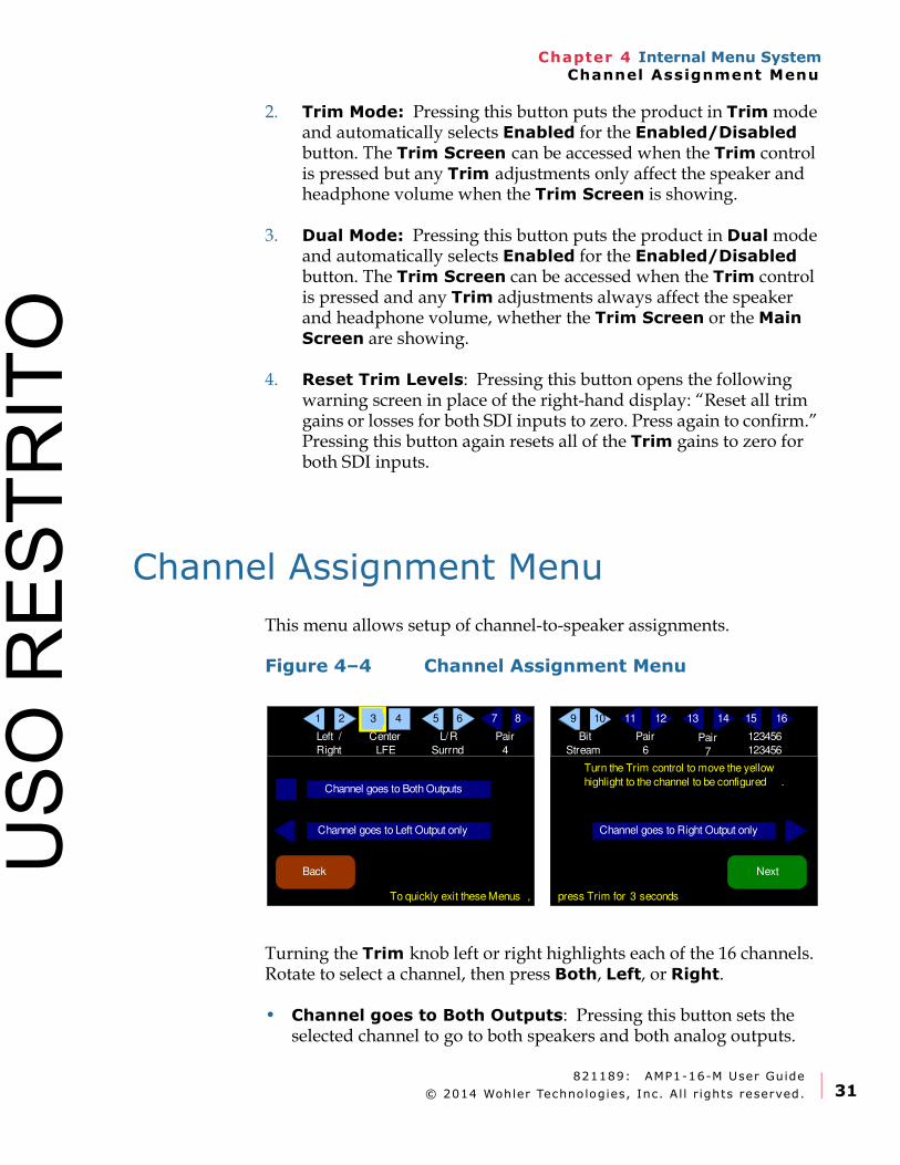
This menu allows setup of channel-to-speaker assignments.
Figure 4–4 Channel Assignment Menu
Turning the Trim knob left or right highlights each of the 16 channels. Rotate to select a channel, then press Both, Left, or Right.
• Channel goes to Both Outputs: Pressing this button sets the selected channel to go to both speakers and both analog outputs.
Channel goes to Left Output only Channel goes to Right Output only
Channel goes to Both Outputs
Turn the Trim control to move the yellow
highlight to the channel to be configured .
NextBack
Left /
Right
Center
LFE
L/R
Surrnd
Bit
Stream
Pair
4
Pair
6Pair
7
123456
123456
421 65 87 1211 1413 1615
To quickly exit these Menus , press Trim for 3 seconds
3 109
USO
RES
TRIT
O
821189: AMP1-16-M User Guide
© 2014 Wohler Technologies, Inc. Al l r ights reserved.32
Chapter 4 Internal Menu SystemOptions Menu
• Channel goes to Left Output only: Pressing this button sets the selected channel to go to the left speaker and to the left analog output.
• Channel goes to Right Output only: Pressing this button sets the selected channel to go to the right speaker and to the right analog output.
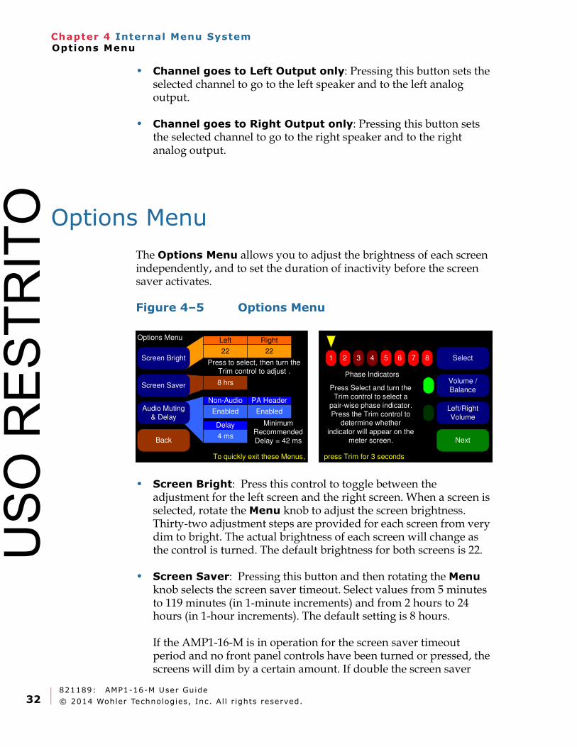
Options Menu
The Options Menu allows you to adjust the brightness of each screen independently, and to set the duration of inactivity before the screen saver activates.
Figure 4–5 Options Menu
• Screen Bright: Press this control to toggle between the adjustment for the left screen and the right screen. When a screen is selected, rotate the Menu knob to adjust the screen brightness. Thirty-two adjustment steps are provided for each screen from very dim to bright. The actual brightness of each screen will change as the control is turned. The default brightness for both screens is 22.
• Screen Saver: Pressing this button and then rotating the Menu knob selects the screen saver timeout. Select values from 5 minutes to 119 minutes (in 1-minute increments) and from 2 hours to 24 hours (in 1-hour increments). The default setting is 8 hours.
If the AMP1-16-M is in operation for the screen saver timeout period and no front panel controls have been turned or pressed, the screens will dim by a certain amount. If double the screen saver
Options Menu
Screen Bright
Back
22 22
Left Right
8 hrsScreen Saver
EnabledAudio Muting
& Delay
Press to select, then turn the Trim control to adjust .
PA HeaderNon-Audio
Enabled
Delay
4 ms
To quickly exit these Menus,
Minimum Recommended
Delay = 42 ms
Select
Volume /
Balance
Left/Right
Volume
Next
2 3 4 5 6 7 8
Press Select and turn the Trim control to select a
pair-wise phase indicator. Press the Trim control to
determine whether
indicator will appear on the meter screen.
Phase Indicators
1
press Trim for 3 seconds
USO
RES
TRIT
O
821189: AMP1-16-M User Guide
© 2014 Wohler Technologies, Inc. Al l r ights reserved. 33
Chapter 4 Internal Menu SystemOptions Menu
timeout period elapses without any front panel control activity, the screens will dim further. Operating any button or control will instantly brighten the screens.
• Audio Muting & Delay: Pressing this button selects the Non-Audio, PA Header, and Delay adjustment. Rotating the Trim knob changes the selected adjustment within its range. The Non-Audio and PA Header detection can be either enabled or disabled. These controls determine if and how much to mute non-audio signals, such as Dolby bitstreams. The Delay can be either Off or 4 to 160 ms. The default settings are:
• Non-Audio: Enabled
• PA Header: Disabled
• Delay: 4 ms
The AMP1-16-M can detect whether a digital audio stream contains PCM encoding, or some other compressed data format such as Dolby Digital™ , in two different ways.
The bitstream contains a non-audio bit. When set, this indicates that the bitstream is not PCM encoded, and therefore, should be muted. This bit occurs once every 4 ms in a 48 kHz audio stream. Unfortunately, some equipment does not set this bit even when a bitstream is not PCM encoded, or will erroneously set this bit when a bitstream is PCM encoded. Thus, there is also a second method of detection.
This unit can look for special words within the data stream known as PA Headers. These headers occur once every video frame. Assuming the slowest frame rate of 24 FPS, these occur every 42 ms. Thus, the delay should be set to a minimum of 42 ms for this detection method alone. The inherent problem with this detection method is that if the bitstream is altered in any way (gain change, equalization, or other forms of processing) these words will also be scrambled and not detected. However, if the non-audio bit is set correctly, it will survive these processes.
You may choose to employ neither, either, or both detection methods. If the amount of delay entered is too short, there may be a small burst of noise when an incoming audio stream switches from PCM encoding to a compressed format.
• Select: Pressing this button and then rotating the Trim knob selects the phase indicator to be adjusted. Press the Select button to
USO
RES
TRIT
O
821189: AMP1-16-M User Guide
© 2014 Wohler Technologies, Inc. Al l r ights reserved.34
Chapter 4 Internal Menu SystemMeter Type and Reference Menu
turn the selected phase indicator On or Off. When set to On, an out of phase condition for the associated pair will be displayed on the Main Screen and when set to Off, out of phase conditions for the associated pair will not be displayed on the Main Screen. By default all phase indicators are enabled.
• Volume/Balance: Pressing this button causes the front panel knobs to function as Volume and Balance controls. This is the default setting.
• Left/Right Volume: Pressing this button causes the front panel knobs to function as Left Volume and Right Volume controls.
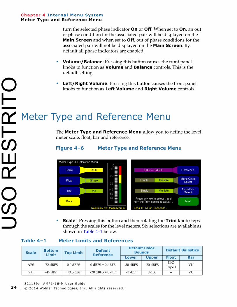
Meter Type and Reference Menu
The Meter Type and Reference Menu allow you to define the level meter scale, float, bar and reference.
Figure 4–6 Meter Type and Reference Menu
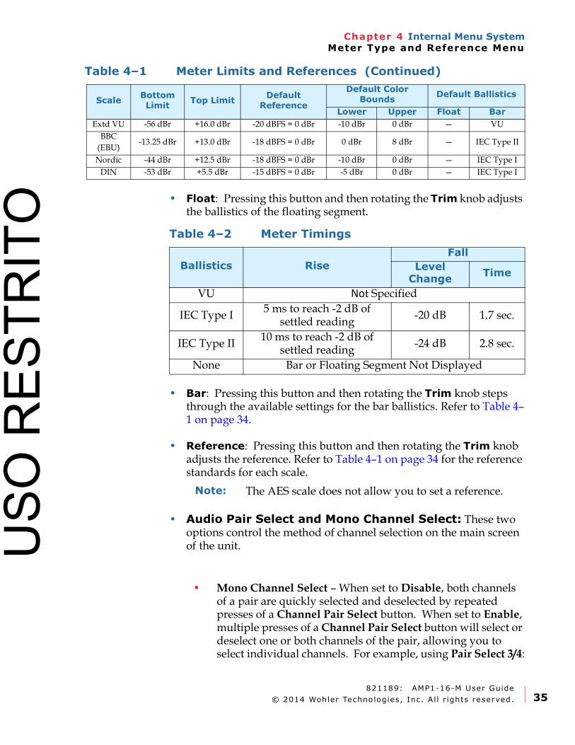
• Scale: Pressing this button and then rotating the Trim knob steps through the scales for the level meters. Six selections are available as shown in Table 4–1 below.
Meter Type & Reference Menu
Back Next
AES
Single
Scale
Float
0
-60
-50
-40
-30
-10
-20
VUBar
Mono Chan . Select
MultipleAudio Pair
Select
0 dBr = 0 dBFS Reference
To quickly exit these Menus Press TRIM for 3 seconds .
Press any key to select , and turn the Trim control to adjust .
Single
DisableEnable
Table 4–1 Meter Limits and References
ScaleBottom
LimitTop Limit
Default
Reference
Default Color Bounds
Default Ballistics
Lower Upper Float Bar
AES -72 dBFS 0.0 dBFS 0 dBFS = 0 dBFS -30 dBFS -20 dBFSIEC
Type IVU
VU -45 dBr +3.5 dBr -20 dBFS = 0 dBr -3 dBr 0 dBr — VU
USO
RES
TRIT
O
821189: AMP1-16-M User Guide
© 2014 Wohler Technologies, Inc. Al l r ights reserved. 35
Chapter 4 Internal Menu SystemMeter Type and Reference Menu
• Float: Pressing this button and then rotating the Trim knob adjusts the ballistics of the floating segment.
• Bar: Pressing this button and then rotating the Trim knob steps through the available settings for the bar ballistics. Refer to Table 4–1 on page 34.
• Reference: Pressing this button and then rotating the Trim knob adjusts the reference. Refer to Table 4–1 on page 34 for the reference standards for each scale.
• Audio Pair Select and Mono Channel Select: These two options control the method of channel selection on the main screen of the unit.
• Mono Channel Select – When set to Disable, both channels of a pair are quickly selected and deselected by repeated presses of a Channel Pair Select button. When set to Enable, multiple presses of a Channel Pair Select button will select or deselect one or both channels of the pair, allowing you to select individual channels. For example, using Pair Select 3/4:
Extd VU -56 dBr +16.0 dBr -20 dBFS = 0 dBr -10 dBr 0 dBr — VU
BBC
(EBU)-13.25 dBr +13.0 dBr -18 dBFS = 0 dBr 0 dBr 8 dBr — IEC Type II
Nordic -44 dBr +12.5 dBr -18 dBFS = 0 dBr -10 dBr 0 dBr — IEC Type I
DIN -53 dBr +5.5 dBr -15 dBFS = 0 dBr -5 dBr 0 dBr — IEC Type I
Table 4–1 Meter Limits and References (Continued)
ScaleBottom Limit
Top LimitDefault Reference
Default Color Bounds
Default Ballistics
Lower Upper Float Bar
Table 4–2 Meter Timings
Ballistics Rise
Fall
Level Change
Time
VU Not Specified
IEC Type I5 ms to reach -2 dB of settled reading
-20 dB 1.7 sec.
IEC Type II10 ms to reach -2 dB of
settled reading-24 dB 2.8 sec.
None Bar or Floating Segment Not Displayed
Note: The AES scale does not allow you to set a reference.
USO
RES
TRIT
O

821189: AMP1-16-M User Guide
© 2014 Wohler Technologies, Inc. Al l r ights reserved.36
Chapter 4 Internal Menu SystemMeter Type and Reference Menu
o First press selects both channels for listening.
o Second press leaves only channel 3 selected.
o Third press leaves only channel 4 selected.
o Fourth press leaves both channels 3 and 4 deselected.
• Audio Pair Select – When set to Single, only one pair may be selected at any given time. Selecting any given pair will first deselect any other pairs. When set to Multiple, any number of pairs may be selected at one time for listening.
USO
RES
TRIT
O
821189: AMP1-16-M User Guide
© 2014 Wohler Technologies, Inc. Al l r ights reserved. 37
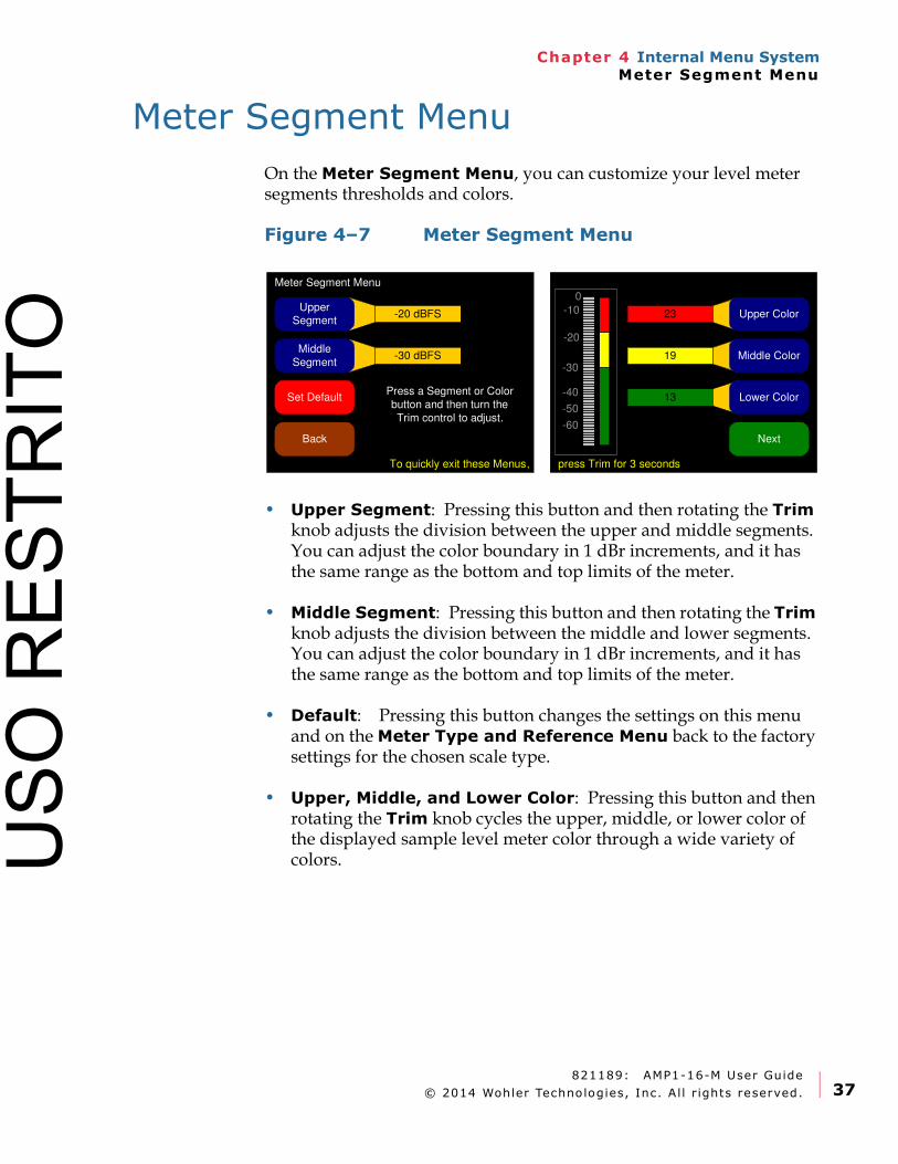
Chapter 4 Internal Menu SystemMeter Segment Menu
Meter Segment Menu
On the Meter Segment Menu, you can customize your level meter segments thresholds and colors.
Figure 4–7 Meter Segment Menu
• Upper Segment: Pressing this button and then rotating the Trim knob adjusts the division between the upper and middle segments. You can adjust the color boundary in 1 dBr increments, and it has the same range as the bottom and top limits of the meter.
• Middle Segment: Pressing this button and then rotating the Trim knob adjusts the division between the middle and lower segments. You can adjust the color boundary in 1 dBr increments, and it has the same range as the bottom and top limits of the meter.
• Default: Pressing this button changes the settings on this menu and on the Meter Type and Reference Menu back to the factory settings for the chosen scale type.
• Upper, Middle, and Lower Color: Pressing this button and then rotating the Trim knob cycles the upper, middle, or lower color of the displayed sample level meter color through a wide variety of colors.
Meter Segment Menu
Set Default
23
19
13
Upper Color
Middle Color
Lower Color
0
-60
-50
-40
-30
-10
-20
-20 dBFS
-30 dBFS
Upper Segment
Middle
Segment
NextBack
Press a Segment or Color
button and then turn the
Trim control to adjust.
To quickly exit these Menus, press Trim for 3 seconds
USO
RES
TRIT
O
821189: AMP1-16-M User Guide
© 2014 Wohler Technologies, Inc. Al l r ights reserved.38
Chapter 4 Internal Menu SystemVersion and Ethernet Menu
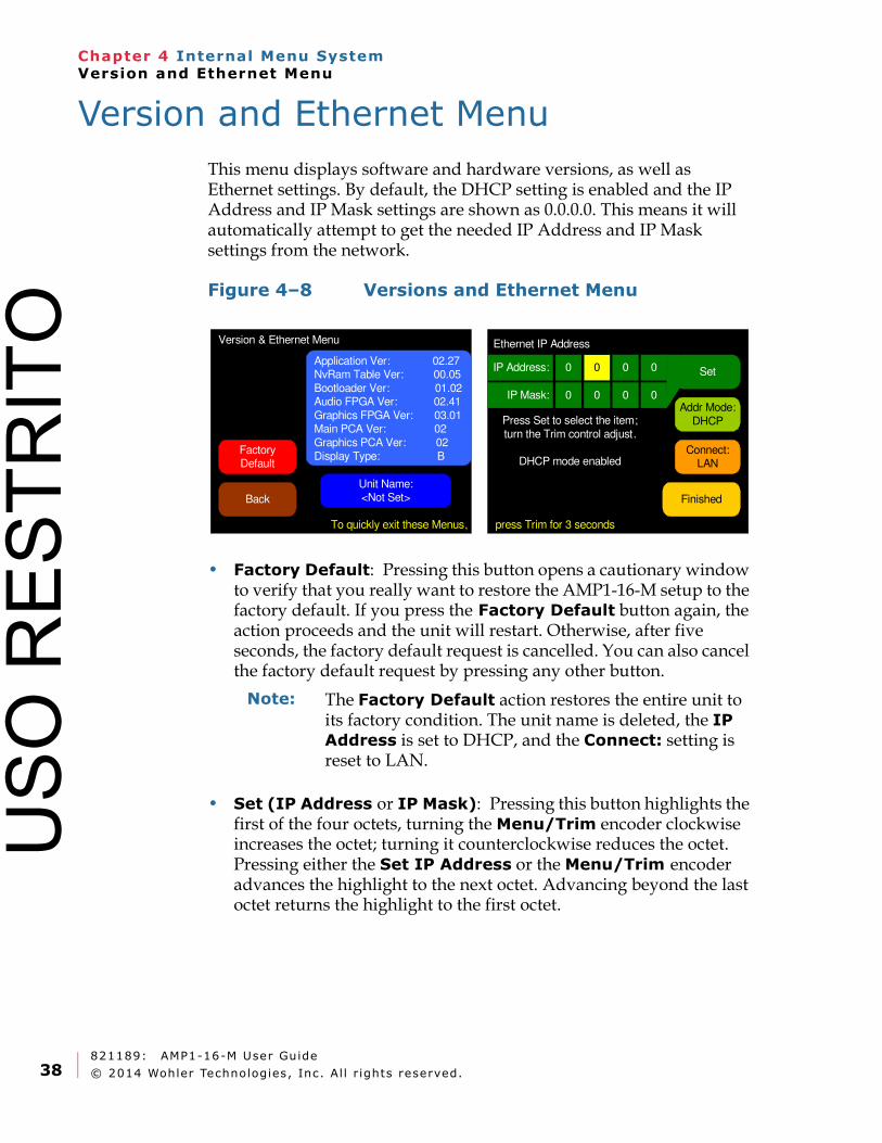
Version and Ethernet Menu
This menu displays software and hardware versions, as well as Ethernet settings. By default, the DHCP setting is enabled and the IP Address and IP Mask settings are shown as 0.0.0.0. This means it will automatically attempt to get the needed IP Address and IP Mask settings from the network.
Figure 4–8 Versions and Ethernet Menu
• Factory Default: Pressing this button opens a cautionary window to verify that you really want to restore the AMP1-16-M setup to the factory default. If you press the Factory Default button again, the action proceeds and the unit will restart. Otherwise, after five seconds, the factory default request is cancelled. You can also cancel the factory default request by pressing any other button.
• Set (IP Address or IP Mask): Pressing this button highlights the first of the four octets, turning the Menu/Trim encoder clockwise increases the octet; turning it counterclockwise reduces the octet. Pressing either the Set IP Address or the Menu/Trim encoder advances the highlight to the next octet. Advancing beyond the last octet returns the highlight to the first octet.
Version & Ethernet Menu
Back
Factory Default
To quickly exit these Menus,
Unit Name:<Not Set>
Application Ver: 02.27NvRam Table Ver: 00.05
Bootloader Ver: 01.02Audio FPGA Ver: 02.41
Graphics FPGA Ver: 03.01Main PCA Ver: 02
Graphics PCA Ver: 02
Display Type: B
Finished
Ethernet IP Address
IP Address: 0
IP Mask: 0
0
0
0
0
0
0
Press Set to select the item;
turn the Trim control adjust.
DHCP mode enabled
press Trim for 3 seconds
Set
Addr Mode:
DHCP
Connect:LAN
Note: The Factory Default action restores the entire unit to its factory condition. The unit name is deleted, the IP Address is set to DHCP, and the Connect: setting is reset to LAN.
USO
RES
TRIT
O
821189: AMP1-16-M User Guide
© 2014 Wohler Technologies, Inc. Al l r ights reserved. 39
Chapter 4 Internal Menu SystemVersion and Ethernet Menu
• Addr Mode: Pressing this button selects between DHCP and Static address modes. Note: Switching to a static IP will automatically cancel the direct connection selection.
• Connect: Pressing this button selects between a LAN connection and a Direct connection. Note: Choosing the direct connection will automatically put the unit into DHCP mode.
• Finished: Pressing this button closes this menu and returns to the Monitoring Screen.
Important: If the IP information has been changed, the unit will have to restart. A warning diamond will display, and you will need to confirm or cancel before proceeding.
If the information in the IP fields is not correct, the changes made in the IP fields will be ignored. The IP address is valid if the screen reads “DHCP Mode Enabled” or “Static IP Mode Enabled.”
Important: This enables a single-address DHCP server. Thus, when a computer is connected directly, both the unit and the host computer will be assigned a DHCP address, and they will be able to communicate. However, this setting will cause problems with some LANs. If this unit will be connected to a LAN, leave this setting in the Connect: LAN setting which disables the internal DHCP server.
USO
RES
TRIT
O

821189: AMP1-16-M User Guide
© 2014 Wohler Technologies, Inc. Al l r ights reserved.40
Chapter 4 Internal Menu SystemVersion and Ethernet Menu
USO
RES
TRIT
O
821189: AMP1-16-M User Guide
© 2014 Wohler Technologies, Inc. Al l r ights reserved. 41
Chapter 5 Features and SpecificationsIntroduction
CHAPTER 5
Features andSpecifications
Introduction
Overview
This chapter lists the features and specifications of the features and options of each local, internal menu.
Topics
Topics Page
Introduction 41
Features 42
Specifications 43
Technical Functional Overview 45
USO
RES
TRIT
O
821189: AMP1-16-M User Guide
© 2014 Wohler Technologies, Inc. Al l r ights reserved.42
Chapter 5 Features and SpecificationsFeatures
Features
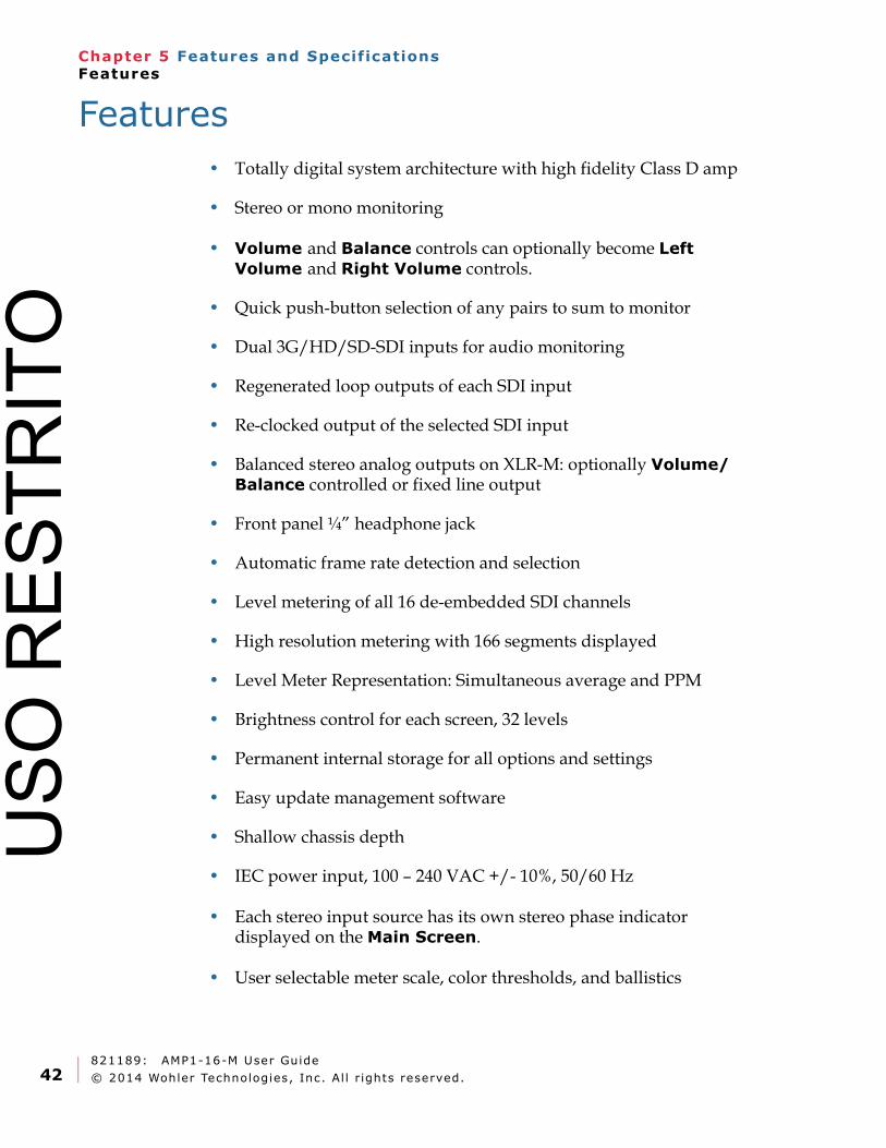
• Totally digital system architecture with high fidelity Class D amp
• Stereo or mono monitoring
• Volume and Balance controls can optionally become Left Volume and Right Volume controls.
• Quick push-button selection of any pairs to sum to monitor
• Dual 3G/HD/SD-SDI inputs for audio monitoring
• Regenerated loop outputs of each SDI input
• Re-clocked output of the selected SDI input
• Balanced stereo analog outputs on XLR-M: optionally Volume/Balance controlled or fixed line output
• Front panel ¼” headphone jack
• Automatic frame rate detection and selection
• Level metering of all 16 de-embedded SDI channels
• High resolution metering with 166 segments displayed
• Level Meter Representation: Simultaneous average and PPM
• Brightness control for each screen, 32 levels
• Permanent internal storage for all options and settings
• Easy update management software
• Shallow chassis depth
• IEC power input, 100 – 240 VAC +/- 10%, 50/60 Hz
• Each stereo input source has its own stereo phase indicator displayed on the Main Screen.
• User selectable meter scale, color thresholds, and ballistics
USO
RES
TRIT
O
821189: AMP1-16-M User Guide
© 2014 Wohler Technologies, Inc. Al l r ights reserved. 43
Chapter 5 Features and SpecificationsCompliance
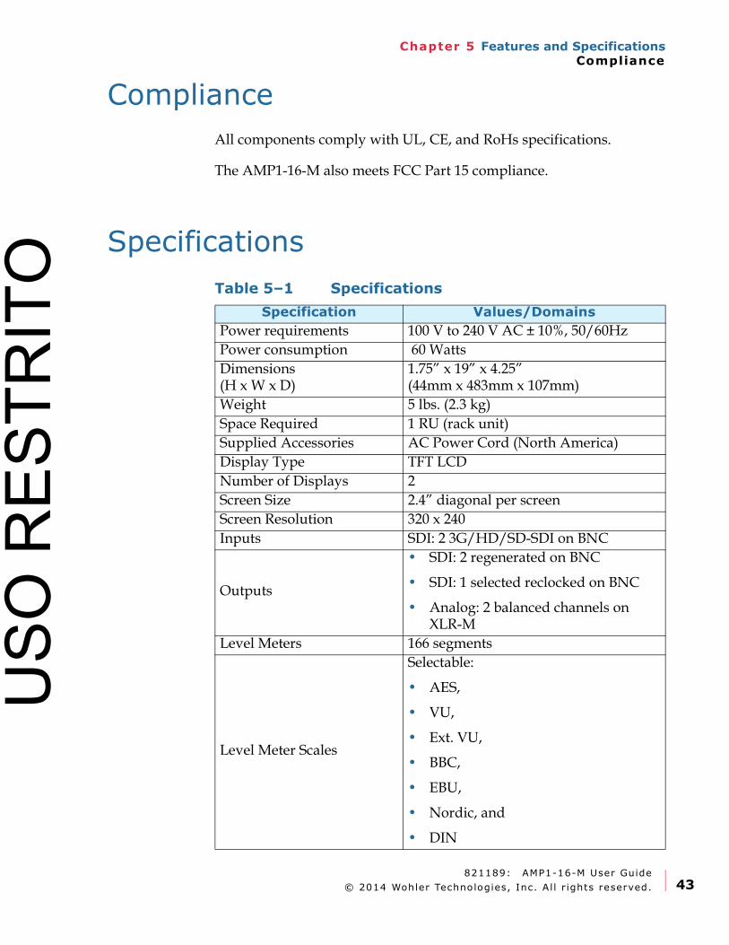
Compliance
All components comply with UL, CE, and RoHs specifications.
The AMP1-16-M also meets FCC Part 15 compliance.
Specifications
Table 5–1 Specifications
Specification Values/Domains
Power requirements 100 V to 240 V AC ± 10%, 50/60Hz
Power consumption 60 Watts
Dimensions(H x W x D)
1.75” x 19” x 4.25”(44mm x 483mm x 107mm)
Weight 5 lbs. (2.3 kg)
Space Required 1 RU (rack unit)
Supplied Accessories AC Power Cord (North America)
Display Type TFT LCD
Number of Displays 2
Screen Size 2.4” diagonal per screen
Screen Resolution 320 x 240
Inputs SDI: 2 3G/HD/SD-SDI on BNC
Outputs
• SDI: 2 regenerated on BNC
• SDI: 1 selected reclocked on BNC
• Analog: 2 balanced channels on XLR-M
Level Meters 166 segments
Level Meter Scales
Selectable:
• AES,
• VU,
• Ext. VU,
• BBC,
• EBU,
• Nordic, and
• DIN
USO
RES
TRIT
O
821189: AMP1-16-M User Guide
© 2014 Wohler Technologies, Inc. Al l r ights reserved.44
Chapter 5 Features and SpecificationsAudio Formats
Audio Formats
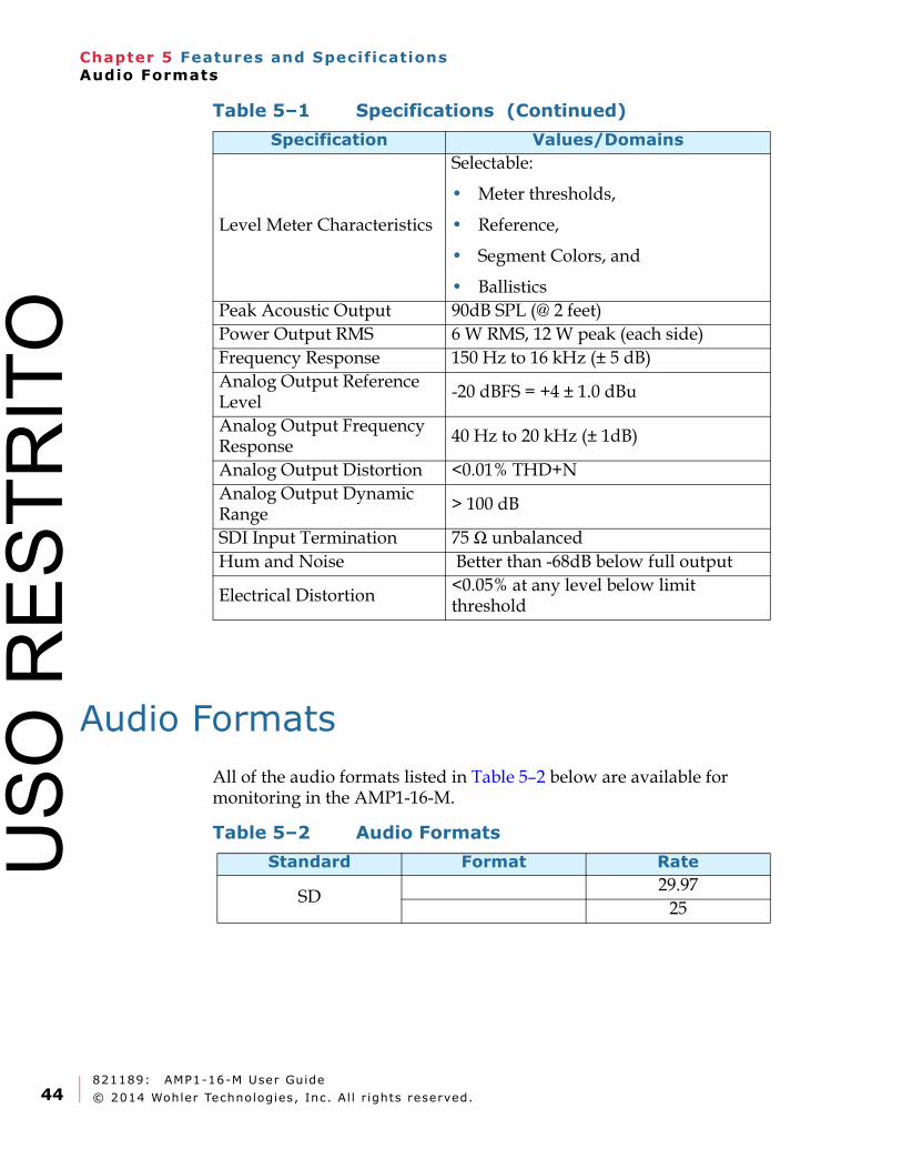
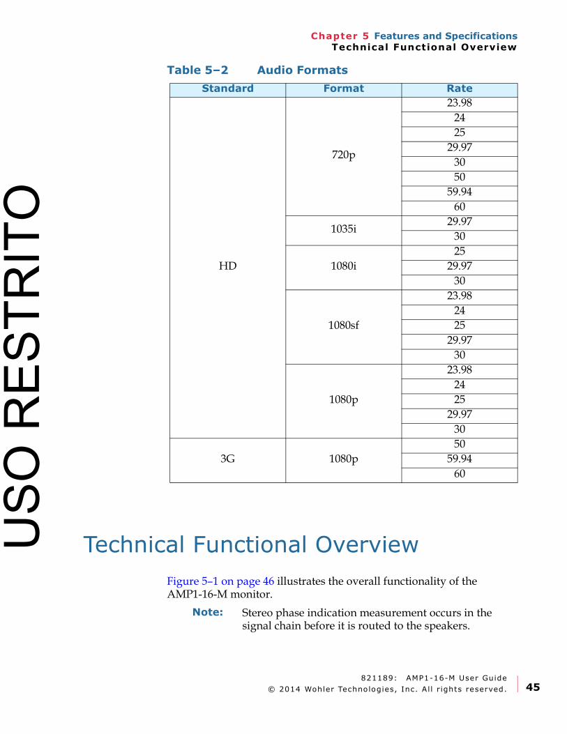
All of the audio formats listed in Table 5–2 below are available for monitoring in the AMP1-16-M.
Level Meter Characteristics
Selectable:
• Meter thresholds,
• Reference,
• Segment Colors, and
• Ballistics
Peak Acoustic Output 90dB SPL (@ 2 feet)
Power Output RMS 6 W RMS, 12 W peak (each side)
Frequency Response 150 Hz to 16 kHz (± 5 dB)
Analog Output Reference Level
-20 dBFS = +4 ± 1.0 dBu
Analog Output Frequency Response
40 Hz to 20 kHz (± 1dB)
Analog Output Distortion <0.01% THD+N
Analog Output Dynamic Range
> 100 dB
SDI Input Termination 75 Ω unbalanced
Hum and Noise Better than -68dB below full output
Electrical Distortion<0.05% at any level below limit threshold
Table 5–1 Specifications (Continued)
Specification Values/Domains
Table 5–2 Audio Formats
Standard Format Rate
SD29.97
25
USO
RES
TRIT
O
821189: AMP1-16-M User Guide
© 2014 Wohler Technologies, Inc. Al l r ights reserved. 45
Chapter 5 Features and SpecificationsTechnical Functional Overview
Technical Functional Overview
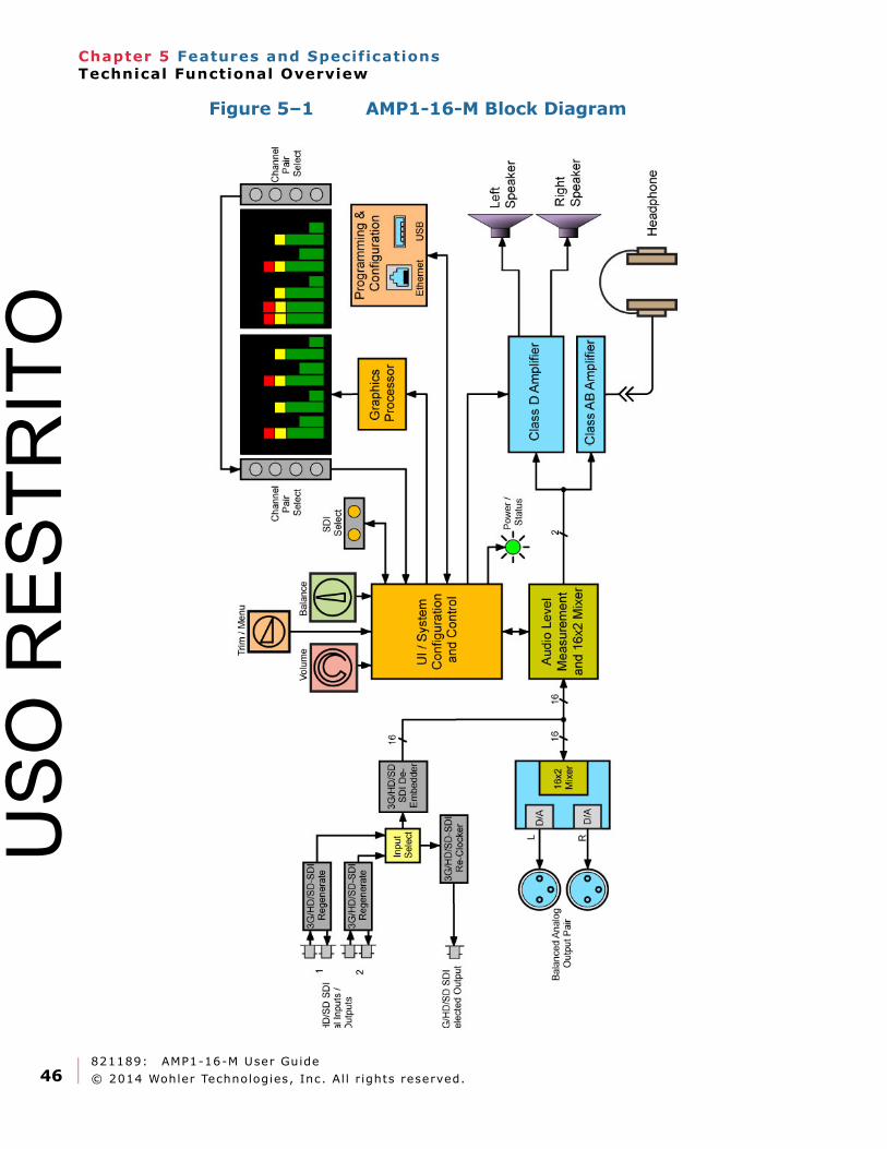
Figure 5–1 on page 46 illustrates the overall functionality of the AMP1-16-M monitor.
HD
720p
23.98
24
25
29.97
30
50
59.94
60
1035i29.97
30
1080i
25
29.97
30
1080sf
23.98
24
25
29.97
30
1080p
23.98
24
25
29.97
30
3G 1080p
50
59.94
60
Table 5–2 Audio Formats
Standard Format Rate
Note: Stereo phase indication measurement occurs in the signal chain before it is routed to the speakers.
USO
RES
TRIT
O
821189: AMP1-16-M User Guide
© 2014 Wohler Technologies, Inc. Al l r ights reserved.46
Chapter 5 Features and SpecificationsTechnical Functional Overview
Figure 5–1 AMP1-16-M Block Diagram
USO
RES
TRIT
O
821189: AMP1-16-M User Guide
© 2014 Wohler Technologies, Inc. Al l r ights reserved. 47
Appendix A Connecting the AMP1-16-M to a LANIntroduction
APPENDIX A
Connecting theAMP1-16-M to a LAN
Introduction
Overview
This chapter describes how to connect your PC to your AMP1-16-M through a local area network (LAN) and to configure the monitor using the graphical user interface (GUI) on a PC.
Alternatively, you may connect your unit to your computer directly with a single Ethernet cable. See Appendix B for instructions regarding this method.
If you have not already installed the AMP1-16-M Manager software on your PC, Please continue with these instructions until the manager has been installed.
Topics
Topics Page
Introduction 47
Requirements 48
Downloading the File 48
Installing the AMP1-16-M Manager 49
Launching the AMP1-16-M Manager 50
Adding Your AMP1-16-M to Your Network 51
USO
RES
TRIT
O
821189: AMP1-16-M User Guide
© 2014 Wohler Technologies, Inc. Al l r ights reserved.48
Appendix A Connecting the AMP1-16-M to a LANRequirements
Requirements
• You must have a PC or laptop that:
• Is running Windows XP, Vista, or Windows 7,
• Is connected to a LAN, and
• Has access to the Internet.
• An IP address from your network administrator (not required if your network uses DHCP)
• An IP mask from your network administrator (not required if your network uses DHCP)
• A standard Ethernet cable to connect the AMP1-16-M to your LAN
• Your product’s serial number (if you have not already created a user ID and password for the Wohler web site)
Downloading the File
You will need to download the AMP1-16-M Manager from the Wohler web site.
1. Power up your PC and create a folder on your desktop called AMP1-16-M.
2. Launch the web browser and navigate to the Wohler web site: www.wohler.com.
Decision Point:
If you already have a member user ID and password for the Wohler web site, then log in by clicking on the Member Sign In link at the top right hand corner of the home page and sign in.
Otherwise, if you do not already have a member user ID and password then you must click Register as New User at the top right hand corner of the home page, and enter the requested data. Remember to log in after you have created your account.
USO
RES
TRIT
O
821189: AMP1-16-M User Guide
© 2014 Wohler Technologies, Inc. Al l r ights reserved. 49
Appendix A Connecting the AMP1-16-M to a LANInstalling the AMP1-16-M Manager
3. Once you have successfully logged into the Wohler web site, click Products from the home page menu bar and go through the sub-menus to locate AMP1-16-M.
A. Click on AMP1-16-M.
B. When the AMP1-16-M web page displays, click on the Downloads tab in the middle of the page.
4. Download the AMP1-16-M configuration Manager.
A. Click on the AMP1-16-M Update Package folder to begin the download.
B. When the File Download dialog appears, click Save.
C. When the Save As dialog appears, navigate to the folder you created in Step 1 on page 48 and click Save.
5. Double-click the ZIP package on the desktop to display the contents.
6. Extract the file(s) to the folder you created in Step 1 on your desktop.
Installing the AMP1-16-M Manager
Right-click on the AMP1-16-M Manager.exe file and choose Run as Administrator. Follow the on-screen instructions to complete the installation.
Important: You must use an extracted setup file. Running the installer from within the .zip file does not work.
USO
RES
TRIT
O
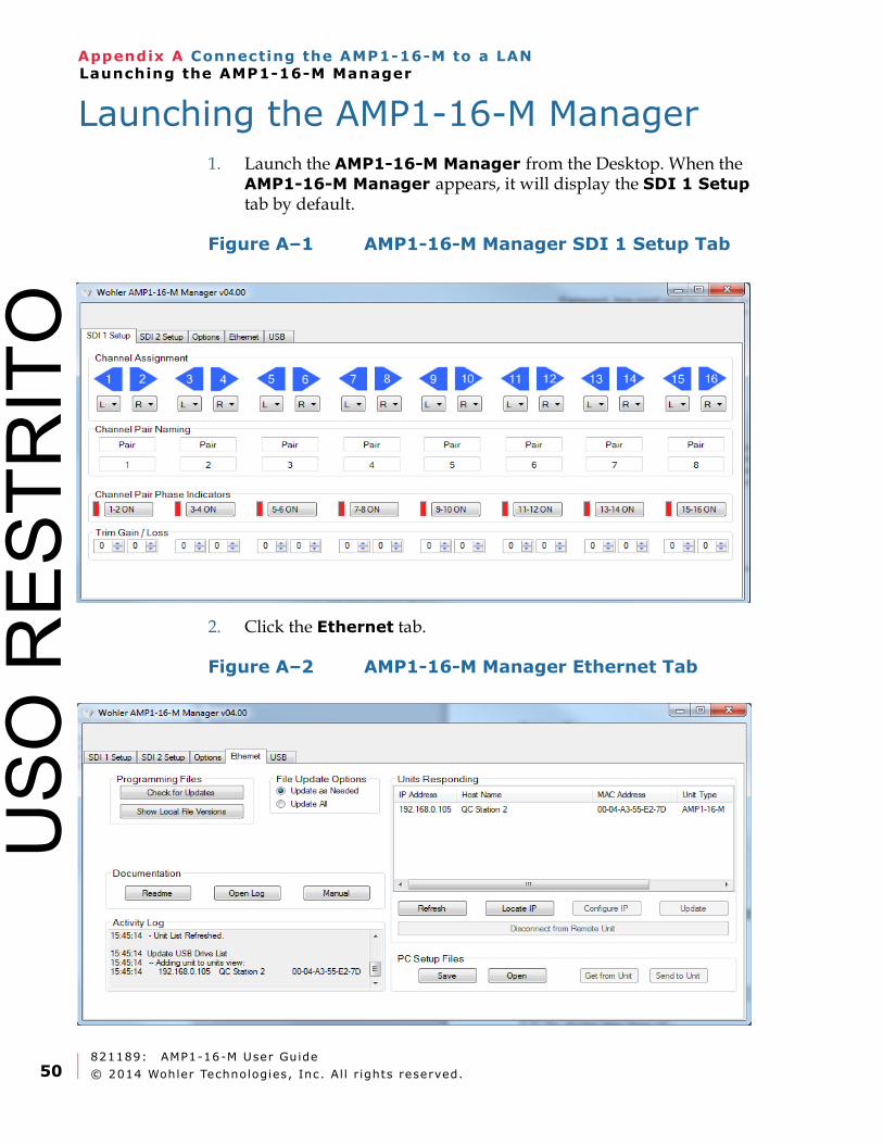
821189: AMP1-16-M User Guide
© 2014 Wohler Technologies, Inc. Al l r ights reserved.50
Appendix A Connecting the AMP1-16-M to a LANLaunching the AMP1-16-M Manager
Launching the AMP1-16-M Manager
1. Launch the AMP1-16-M Manager from the Desktop. When the AMP1-16-M Manager appears, it will display the SDI 1 Setup tab by default.
Figure A–1 AMP1-16-M Manager SDI 1 Setup Tab
2. Click the Ethernet tab.
Figure A–2 AMP1-16-M Manager Ethernet Tab
USO
RES
TRIT
O
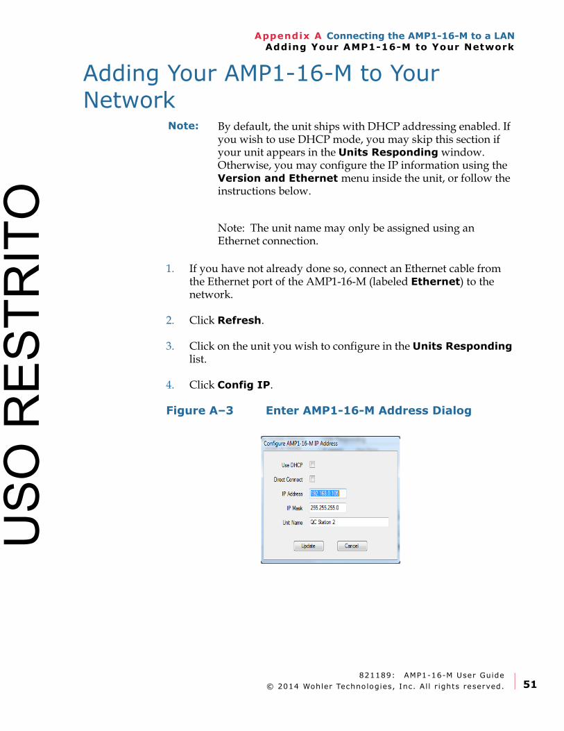
821189: AMP1-16-M User Guide
© 2014 Wohler Technologies, Inc. Al l r ights reserved. 51
Appendix A Connecting the AMP1-16-M to a LANAdding Your AMP1-16-M to Your Network
Adding Your AMP1-16-M to Your Network
1. If you have not already done so, connect an Ethernet cable from the Ethernet port of the AMP1-16-M (labeled Ethernet) to the network.
2. Click Refresh.
3. Click on the unit you wish to configure in the Units Responding list.
4. Click Config IP.
Figure A–3 Enter AMP1-16-M Address Dialog
Note: By default, the unit ships with DHCP addressing enabled. If you wish to use DHCP mode, you may skip this section if your unit appears in the Units Responding window. Otherwise, you may configure the IP information using the Version and Ethernet menu inside the unit, or follow the instructions below.
Note: The unit name may only be assigned using an Ethernet connection.
USO
RES
TRIT
O
821189: AMP1-16-M User Guide
© 2014 Wohler Technologies, Inc. Al l r ights reserved.52
Appendix A Connecting the AMP1-16-M to a LANAdding Your AMP1-16-M to Your Network
5. When the Enter AMP1-16-M IP Address dialog displays, do the following:
A. Click the Use DHCP check box (if needed) to select DHCP
B. Do NOT check Direct Connect if connecting to the unit through a LAN. If you wish to connect to the unit directly, see Appendix B on page 55.
C. Enter the Unit IP address.
D. Enter the Unit IP Mask
E. (Optional) Enter a Unit Name of up to 15 characters. The name you select for this AMP1-16-M should denote its position or function within your facility so that it can be easily recognized later.
F. Click Update to close the dialog. Click Cancel to ignore any changes and return to the previous window. Note: A grayed Update button means the IP information is not correct.
To change the IP settings, the unit must restart. The Windows application will automatically restart the unit, and display the unit with its new address after it has rebooted. This takes approximately 10 seconds.
6. Click Refresh. After the system polls the network, all the AMP1-16-Ms on the network will display in the Units Responding box.
7. If the unit is located on a different subnet than the host computer, the Windows Manager may not be able to automatically locate it. In this case, use the Locate IP button.
Important: If your network uses DHCP, then skip Steps C and D and continue on to Step E below.
USO
RES
TRIT
O
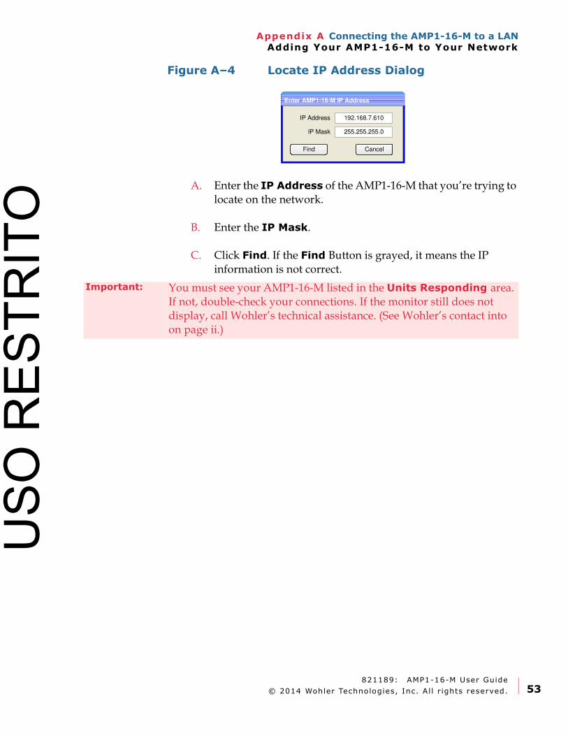
821189: AMP1-16-M User Guide
© 2014 Wohler Technologies, Inc. Al l r ights reserved. 53
Appendix A Connecting the AMP1-16-M to a LANAdding Your AMP1-16-M to Your Network
Figure A–4 Locate IP Address Dialog
A. Enter the IP Address of the AMP1-16-M that you’re trying to locate on the network.
B. Enter the IP Mask.
C. Click Find. If the Find Button is grayed, it means the IP information is not correct.
Enter AMP1-16-M IP Address
IP Address
IP Mask
192.168.7.610
Find Cancel
255.255.255.0
Important: You must see your AMP1-16-M listed in the Units Responding area. If not, double-check your connections. If the monitor still does not display, call Wohler’s technical assistance. (See Wohler’s contact into on page ii.)
USO
RES
TRIT
O

821189: AMP1-16-M User Guide
© 2014 Wohler Technologies, Inc. Al l r ights reserved.54
Appendix A Connecting the AMP1-16-M to a LANAdding Your AMP1-16-M to Your Network
USO
RES
TRIT
O
821189: AMP1-16-M User Guide
© 2013 Wohler Technologies, Inc. Al l r ights reserved. 55
Appendix B Using a Direct ConnectionIntroduction
APPENDIX B
Using a Direct Connection
Introduction
Overview
A direct connection should only be used when a LAN (local area network) is not available. A direct connection to any unit can be difficult if you're not familiar with setting static IP addresses. Fortunately, this unit has a DHCP server embedded in it, which will make a direct connection much easier. All of these instructions may not be needed in your particular situation, but following them ensures success.
Topic
Important: If you have not yet installed the AMP1-16-M Manager setup software into your PC you must do that first. Please see the download and installation instructions in Appendix A before continuing.
Topic Page
Using a Direct Connection 56
USO
RES
TRIT
O
821189: AMP1-16-M User Guide
© 2013 Wohler Technologies, Inc. Al l r ights reserved.56
Appendix B Using a Direct ConnectionUsing a Direct Connection
Using a Direct Connection
1. Disconnect the Computer from any LAN.
2. Disconnect the UNIT from any LAN.
3. Connect the unit to the host computer through either a standard network "patch" cable or "crossover" cable. The unit will recognize which is being used automatically.
4. Turn the unit on, and set the unit for direct mode and DHCP. This can be done in the Version and Ethernet Menu, Connect: Direct. For more information, see the Version and Ethernet Menu description on Page 35.
5. On your host computer, close any running applications, especially those using the internet or maintaining a VPN (virtual private networking) connection.
6. If your host computer has multiple network interfaces (such as wireless and wired Ethernet), disable the ports you will not be using (especially wireless port(s)).
7. Restart your computer.
8. Start the AMP1-16-M Manager.
9. Your unit should eventually appear in the Units Responding window of the Manager GUI. Depending upon your computer, it may take a few minutes for the DHCP negotiations to take place. You may press the Refresh button in the Manager GUI as often as you like until the unit appears. See Figure B-1 below.
Note: If there are static values already entered for the IP Address and IP Mask, you may want to write them down so you can restore those settings later
USO
RES
TRIT
O
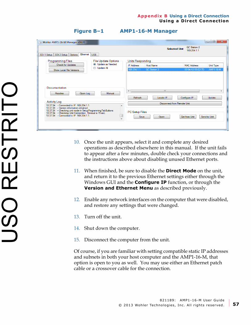
821189: AMP1-16-M User Guide
© 2013 Wohler Technologies, Inc. Al l r ights reserved. 57
Appendix B Using a Direct ConnectionUsing a Direct Connection
Figure B–1 AMP1-16-M Manager
10. Once the unit appears, select it and complete any desired operations as described elsewhere in this manual. If the unit fails to appear after a few minutes, double check your connections and the instructions above about disabling unused Ethernet ports.
11. When finished, be sure to disable the Direct Mode on the unit, and return it to the previous Ethernet settings either through the Windows GUI and the Configure IP function, or through the Version and Ethernet Menu as described previously.
12. Enable any network interfaces on the computer that were disabled, and restore any settings that were changed.
13. Turn off the unit.
14. Shut down the computer.
15. Disconnect the computer from the unit.
Of course, if you are familiar with setting compatible static IP addresses and subnets in both your host computer and the AMP1-16-M, that option is open to you as well. You may use either an Ethernet patch cable or a crossover cable for the connection.
USO
RES
TRIT
O

821189: AMP1-16-M User Guide
© 2013 Wohler Technologies, Inc. Al l r ights reserved.58
Appendix B Using a Direct ConnectionUsing a Direct Connection
USO
RES
TRIT
O
821189: AMP1-16-M User Guide
© 2014 Wohler Technologies, Inc. Al l r ights reserved. 59
Appendix C Upgrading the AMP1-16M using EthernetIntroduction
APPENDIX C
Upgrading the AMP1-16Musing Ethernet
Introduction
Overview
This chapter describes how to download software upgrades to your PC and then transfer and install them to your AMP1-16-M.
There are two methods to update the software in the AMP1-16-M.
1. Use a USB flash drive.
2. Use the AMP1-16-M Manager to update the unit over Ethernet.
NOTE: Option 1 is only available for units with software Version 4.00 or later installed.
Topics
Important: If you have not yet installed the AMP1-16-M Manager setup software into your PC you must do that first. Please see the download and installation instructions in Appendix A before continuing.
Topics Page
Checking for Updates 60
Upgrading the Software Using a USB Flash Drive 62
USO
RES
TRIT
O
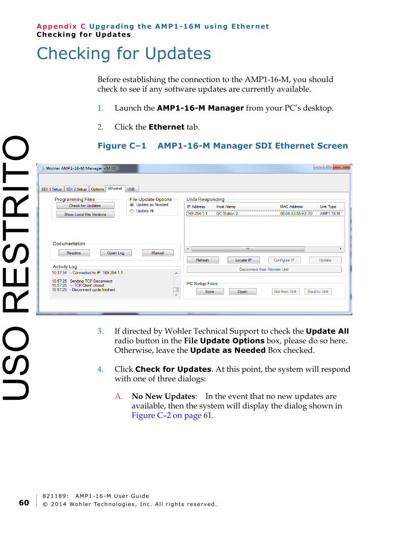
821189: AMP1-16-M User Guide
© 2014 Wohler Technologies, Inc. Al l r ights reserved.60
Appendix C Upgrading the AMP1-16M using EthernetChecking for Updates
Checking for Updates
Before establishing the connection to the AMP1-16-M, you should check to see if any software updates are currently available.
1. Launch the AMP1-16-M Manager from your PC’s desktop.
2. Click the Ethernet tab.
Figure C–1 AMP1-16-M Manager SDI Ethernet Screen
3. If directed by Wohler Technical Support to check the Update All radio button in the File Update Options box, please do so here. Otherwise, leave the Update as Needed Box checked.
4. Click Check for Updates. At this point, the system will respond with one of three dialogs:
A. No New Updates: In the event that no new updates are available, then the system will display the dialog shown in Figure C–2 on page 61.
USO
RES
TRIT
O
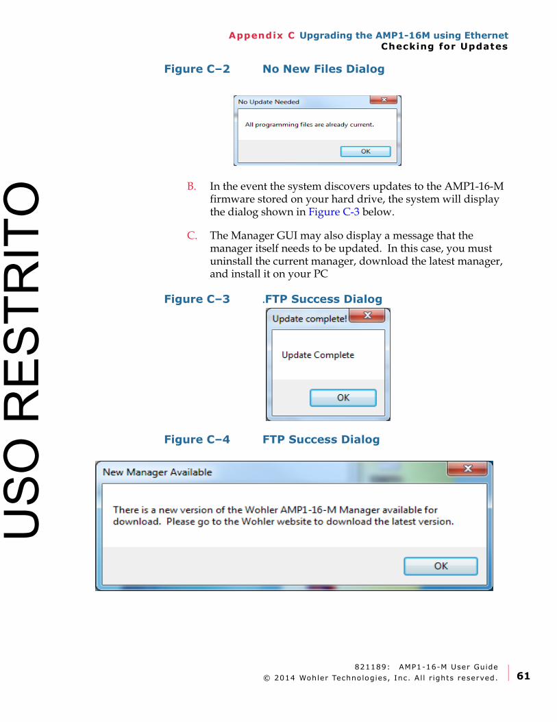
821189: AMP1-16-M User Guide
© 2014 Wohler Technologies, Inc. Al l r ights reserved. 61
Appendix C Upgrading the AMP1-16M using EthernetChecking for Updates
Figure C–2 No New Files Dialog
B. In the event the system discovers updates to the AMP1-16-M firmware stored on your hard drive, the system will display the dialog shown in Figure C-3 below.
C. The Manager GUI may also display a message that the manager itself needs to be updated. In this case, you must uninstall the current manager, download the latest manager, and install it on your PC
Figure C–3 .FTP Success Dialog
Figure C–4 FTP Success Dialog
USO
RES
TRIT
O
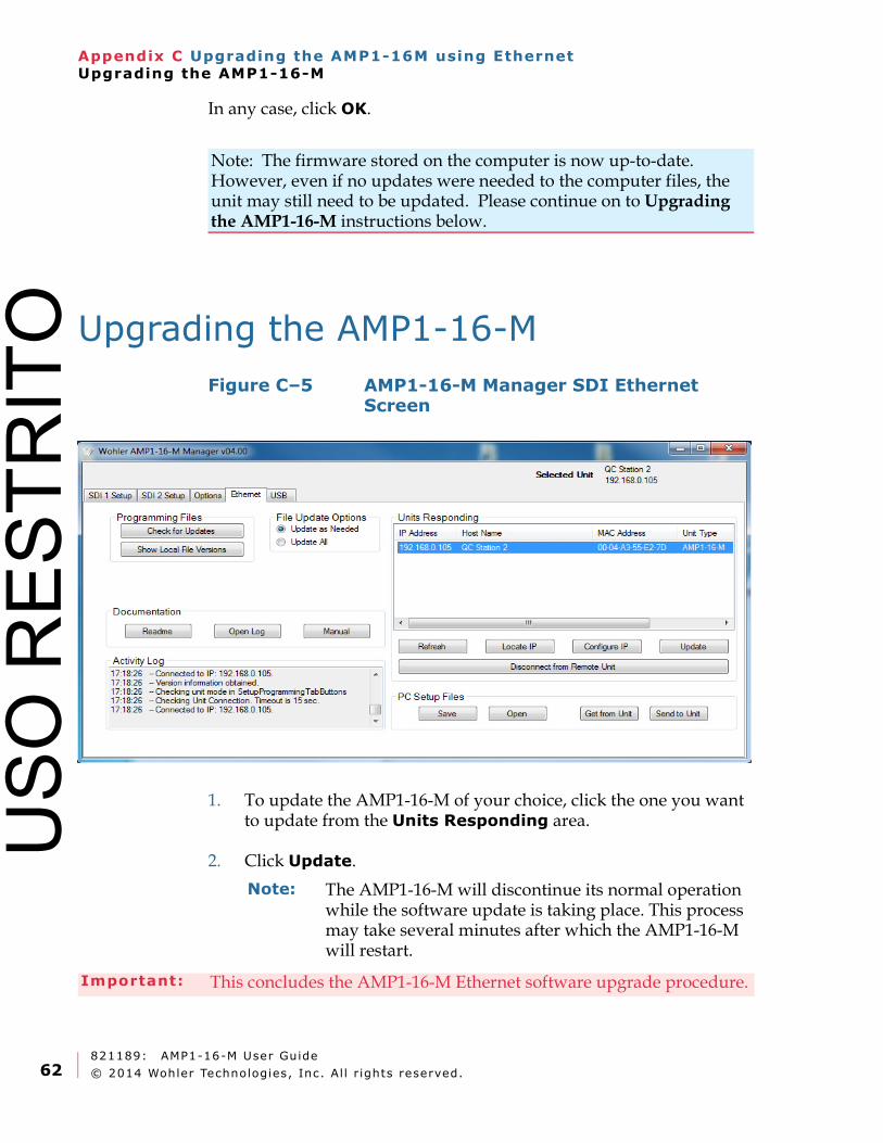
821189: AMP1-16-M User Guide
© 2014 Wohler Technologies, Inc. Al l r ights reserved.62
Appendix C Upgrading the AMP1-16M using EthernetUpgrading the AMP1-16-M
In any case, click OK.
Upgrading the AMP1-16-M
Figure C–5 AMP1-16-M Manager SDI Ethernet Screen
1. To update the AMP1-16-M of your choice, click the one you want to update from the Units Responding area.
2. Click Update.
Note: The firmware stored on the computer is now up-to-date. However, even if no updates were needed to the computer files, the unit may still need to be updated. Please continue on to Upgrading the AMP1-16-M instructions below.
Note: The AMP1-16-M will discontinue its normal operation while the software update is taking place. This process may take several minutes after which the AMP1-16-M will restart.
Important: This concludes the AMP1-16-M Ethernet software upgrade procedure.
USO
RES
TRIT
O

821189: AMP1-16-M User Guide
© 2014 Wohler Technologies, Inc. Al l r ights reserved. 63
Appendix D Upgrading the AMP1-16-M Using a USB Flash DriveIntroduction
APPENDIX D
Upgrading the AMP1-16-MUsing a USB Flash Drive
Introduction
Overview
This chapter describes how to download software upgrades to your PC using a USB Flash Drive.
Topic
Important: If you have not already done so, place a software update onto the flash drive using the instructions in Programming Files on page 26. USB software updates can be only performed if the unit has firmware version 4.00 or later. Units with earlier software versions must be update using the Ethernet port.
Topic Page
Upgrading the Software Using a USB Flash Drive 64USO
RES
TRIT
O

821189: AMP1-16-M User Guide
© 2014 Wohler Technologies, Inc. Al l r ights reserved.64
Appendix D Upgrading the AMP1-16-M Using a USB Flash DriveUpgrading the Software Using a USB Flash Drive
Upgrading the Software Using a USB Flash Drive
1. 1. Insert the USB flash drive into the unit.
2. 2. If the USB flash drive has firmware files on it, the green Update Menu button will appear on the right screen. If the firmware files are missing, this button will not appear. See Figure D-1 below.
Figure D–1 Flash Drive Connected Screen
3. Press Update Menu.
4. All the firmware files on the USB drive will be read and validated. This will take a few minutes, and progress screens are presented. Once the validation is finished the following menu appears:
Figure D–2 Flash Drive Software Update Screen
Flash Drive Connected
Get System Config . from
Flash Drive
Save System Config . to
Flash Drive
To exit this menu ,
remove the USB device
Get
Save
Update the unit software
from the flash drive .
Update
Menu
Flash Drive Software Update
Update Software
as Needed
Cancel /Quit
To exit without installing
software, press Cancel /Quit
View Versions
Update only the outdated
parts of the software .(Recommended )
Replace Software
Unconditionally
Update the software
regardless of version .(Use cautiously )
The installed software needs an update.
USO
RES
TRIT
O
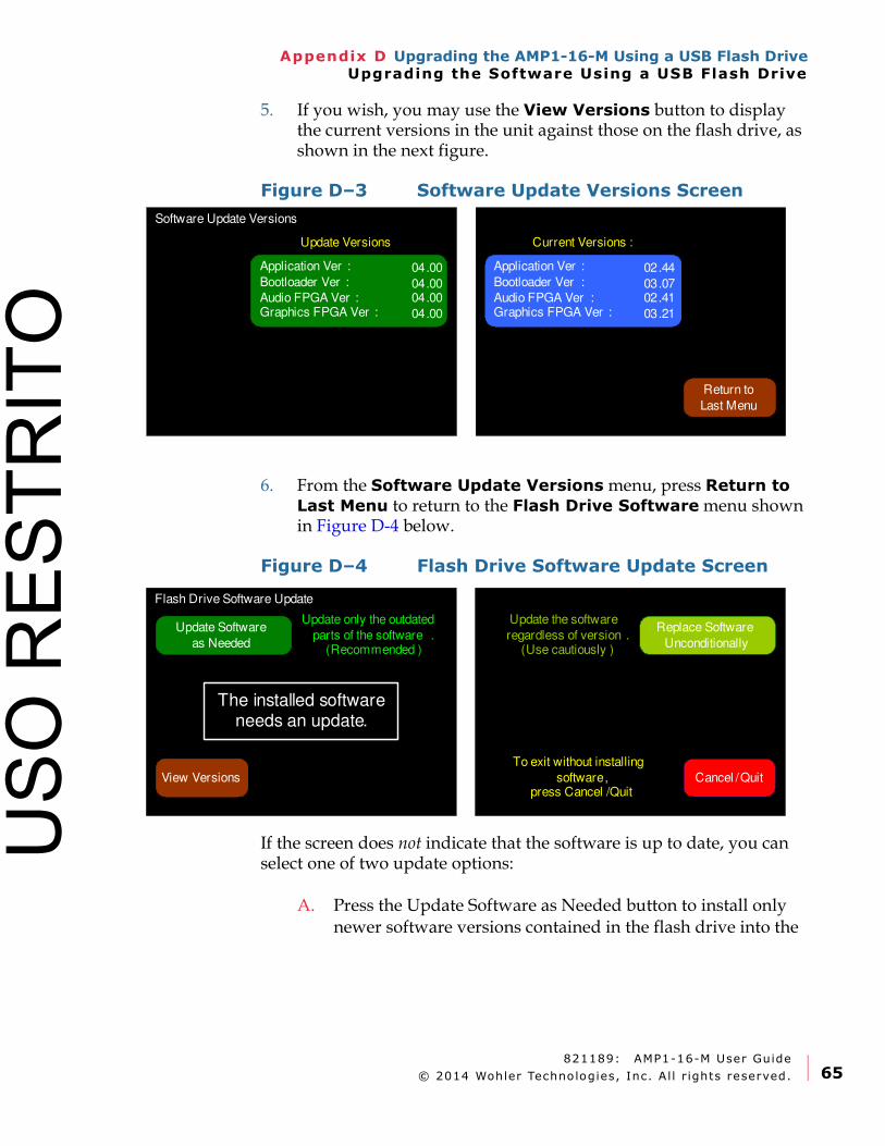
821189: AMP1-16-M User Guide
© 2014 Wohler Technologies, Inc. Al l r ights reserved. 65
Appendix D Upgrading the AMP1-16-M Using a USB Flash DriveUpgrading the Software Using a USB Flash Drive
5. If you wish, you may use the View Versions button to display the current versions in the unit against those on the flash drive, as shown in the next figure.
Figure D–3 Software Update Versions Screen
6. From the Software Update Versions menu, press Return to Last Menu to return to the Flash Drive Software menu shown in Figure D-4 below.
Figure D–4 Flash Drive Software Update Screen
If the screen does not indicate that the software is up to date, you can select one of two update options:
A. Press the Update Software as Needed button to install only newer software versions contained in the flash drive into the
Software Update Versions
Return to
Last Menu
Application Ver :
Bootloader Ver :
Audio FPGA Ver : Graphics FPGA Ver :
Current Versions :Update Versions
Application Ver :
Bootloader Ver :
Audio FPGA Ver :Graphics FPGA Ver :
02.44
03.0702.41
03.21
04.00
04.0004.00
04.00
Flash Drive Software Update
Update Software
as Needed
Cancel /Quit
To exit without installing
software, press Cancel /Quit
View Versions
Update only the outdated
parts of the software .(Recommended )
Replace Software
Unconditionally
Update the software
regardless of version .(Use cautiously )
The installed software needs an update.
USO
RES
TRIT
O
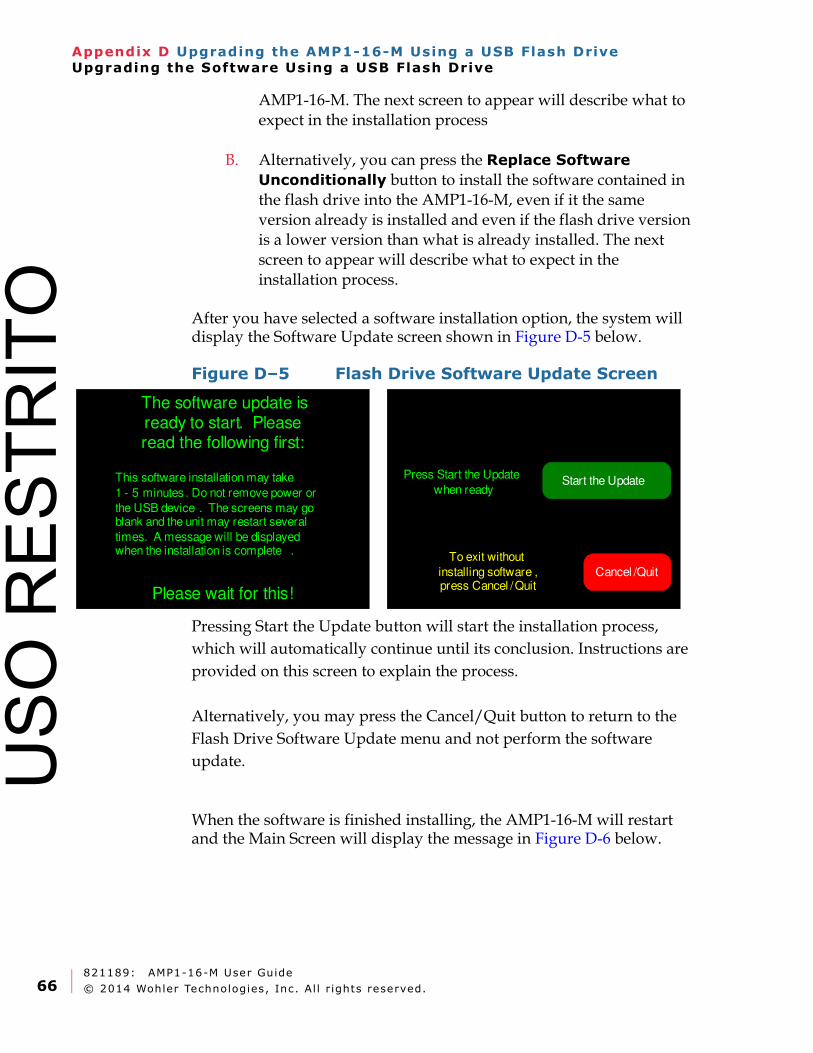
821189: AMP1-16-M User Guide
© 2014 Wohler Technologies, Inc. Al l r ights reserved.66
Appendix D Upgrading the AMP1-16-M Using a USB Flash DriveUpgrading the Software Using a USB Flash Drive
AMP1-16-M. The next screen to appear will describe what to expect in the installation process
B. Alternatively, you can press the Replace Software Unconditionally button to install the software contained in the flash drive into the AMP1-16-M, even if it the same version already is installed and even if the flash drive version is a lower version than what is already installed. The next screen to appear will describe what to expect in the installation process.
After you have selected a software installation option, the system will display the Software Update screen shown in Figure D-5 below.
Figure D–5 Flash Drive Software Update Screen
Pressing Start the Update button will start the installation process,
which will automatically continue until its conclusion. Instructions are
provided on this screen to explain the process.
Alternatively, you may press the Cancel/Quit button to return to the
Flash Drive Software Update menu and not perform the software
update.
When the software is finished installing, the AMP1-16-M will restart and the Main Screen will display the message in Figure D-6 below.
Cancel /Quit
The software update is ready to start. Please read the following first:
Please wait for this!
To exit without
installing software , press Cancel /Quit
Start the UpdatePress Start the Update
when readyThis software installation may take
1 - 5 minutes . Do not remove power or
the USB device . The screens may go blank and the unit may restart several
times. A message will be displayed when the installation is complete .
USO
RES
TRIT
O
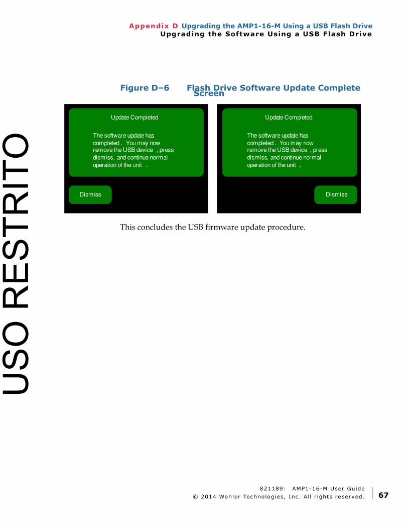
821189: AMP1-16-M User Guide
© 2014 Wohler Technologies, Inc. Al l r ights reserved. 67
Appendix D Upgrading the AMP1-16-M Using a USB Flash DriveUpgrading the Software Using a USB Flash Drive
Figure D–6 Flash Drive Software Update Complete Screen
This concludes the USB firmware update procedure.
Dismiss
Update Completed
The software update has
completed . You may now remove the USB device , press
dismiss, and continue normal
operation of the unit .
Update Completed
The software update has
completed . You may now remove the USB device , press
dismiss, and continue normal
operation of the unit .
Dismiss
USO
RES
TRIT
O

821189: AMP1-16-M User Guide
© 2014 Wohler Technologies, Inc. Al l r ights reserved.68
Appendix D Upgrading the AMP1-16-M Using a USB Flash DriveUpgrading the Software Using a USB Flash Drive
USO
RES
TRIT
O