Embed Size (px)
Citation preview
AMMONIA RECEIVER DESIGN FOR DISH CONCENTRATORS
Rebecca I. Dunn, Keith Lovegrove and Greg Burgess
Solar Thermal Group, Australian National University (ANU)
Department of Engineering, Building 32 North Rd, ACT 0200, Australia. Ph+61 2 6125 4046
Abstract
This paper describes a general method for evaluating receiver designs for ammonia-based energy storage with dish concentrators. The method involves ray-tracing to determine the concentrated solar flux profile on the reactor surface, followed by a simulation which calculates reaction extents and heat losses. In this paper, five receiver designs were investigated with varying cone angles and placements of tubes within the receiver. The receiver designs with highest conversion efficiency were found to be a frustum arrangement of reactor tubes with an angle of 7.5 degrees, and a cylindrical arrangement of reactor tubes with a radius of 77mm. These designs produced receiver efficiencies of 54.9% and 55.3% respectively. This computational receiver design evaluation continues.
Following further experiments with the masked 20m2 dish concentrator, this design process will be able to be applied to the new SG4 Big Dish.
Keywords: energy storage, receiver design, thermochemical storage, dish concentrator.
1. Introduction
Fig. 1. Energy storage using dissociated ammonia as the storage medium at ambient temperature.
Figure 1 illustrates a solar thermochemical energy storage system based on the reversible dissociation of ammonia, first proposed by Carden in 1974 [1]. In this storage system, a fixed inventory of ammonia passes alternately between energy-storing (dissociation) and energy-releasing (synthesis) reactors. The solar-driven dissociation is endothermic, and proceeds from left to right, according to the equation in Figure 1. The energy-releasing synthesis reaction proceeds from right to left, and coupled with a power cycle (Rankine or Brayton), can be used to produce dispatchable power. At 20MPa and 20oC, the enthalpy of reaction is 66.8kJ/mol.
The ANU Solar Thermal Group currently has a prototype ammonia receiver which operates with a 20m2 paraboloidal dish concentrator, shown in Figure 2. In addition, a project to construct a new generation “SG4” Big Dish concentrator on the ANU campus is nearing completion (see Figure 11). This dish will be similar to the existing 400m2 “SG3” generation Big Dish prototype, also shown in Figure 2, but with a 500m2 aperture
NH3 + ΔH ⇌ 2
1 N2 + 2
3 H2
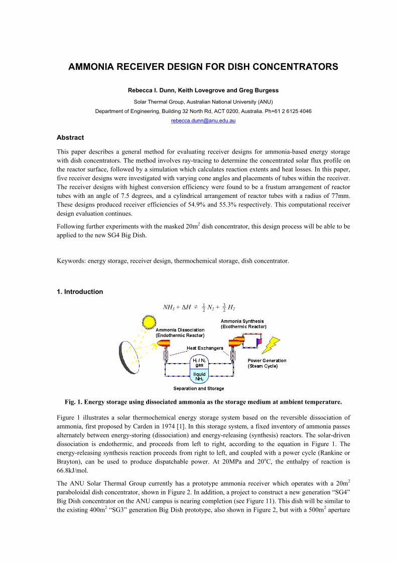
and a modified support structure. This paper presents the latest experimental and modeling results aimed at developing a receiver design for the SG4 Big Dish.
Fig. 2. From left: 20m2 dish; prototype ammonia receiver (insulation removed); 400m2 SG3 Big Dish prototype.
2. Prototype receiver
The prototype ammonia receiver, shown in Figure 2, consists of 20 packed bed catalytic reactor tubes arranged in a frustum inside the insulated cavity receiver. Ammonia dissociation experiments have been successfully performed with this prototype receiver [2], with recent experimental results shown in Figure 3. In addition, a computational model – newre7.for – developed by Lovegrove [3], and more recently revised by Paitoonsurikarn [4], has been used to simulate the reaction in the reactor tubes. This computational model employs the Tymken Pyzhev rate law and finite difference method to determine reaction extents when the incident radiant flux on the tube surface is specified. The model allows for free convection, conduction and radiation losses, and has been calibrated using data from dissociation experiments with the 20m2 dish.
Simulation results with parameters corresponding to the recent dissociation experiments with the 20m2 dish are also shown in Figure 3. The solar-to-chemical efficiency represents the ratio of the energy stored in the bonds of the nitrogen and hydrogen product gases – as per the synthesis reaction in Figure 1 – to the total radiation incident on the dish surface. The receiver efficiency represents the ratio of stored energy to the radiation that enters the receiver aperture – that is, as if there were no reflection or tracking losses. In the experiment shown in Figure 3, the dissociation efficiencies obtained were up to 6% lower than those predicted by the model. However, with the collection of more experimental data points, closer agreement is expected. The disagreement in Figure 3 is in part due to deteriorated insulation on the receiver shield and the absence of forced convection losses in the current computational model.
Fig. 3. Dissociation efficiencies for experiments performed on 15-16th January 2009 with a solar altitude of 75o, insolation of 1010W/m2, system pressure of 10MPa, and average wind speed of 2.8m/s.
3. Receiver design for the SG4 Big Dish
Aside from scaling issues, there is a marked difference in rim angles between the 20m2 dish concentrator and the SG4 Big Dish concentrator – being 70o and 50o respectively. An experiment is thus underway to perform ammonia dissociation with the 20m2 dish in which the outer rim of the dish is masked with opaque film to mimic a 50o rim angle, as shown in Figure 4. The aim of this experiment is to determine which receiver designs yield the highest solar-to-chemical conversion efficiencies. To date, this has involved:
• Characterizing the masked 20m2 dish with a flux map.
• Modeling five different receiver geometries in OptiCAD 10.0.
• Determining the concentrated solar flux profiles on the reactor tubes by ray-tracing with OptiCAD.
• Simulating the chemical reaction in each of the five receivers using the ray-trace flux profiles.
3.1 Determining the flux profiles
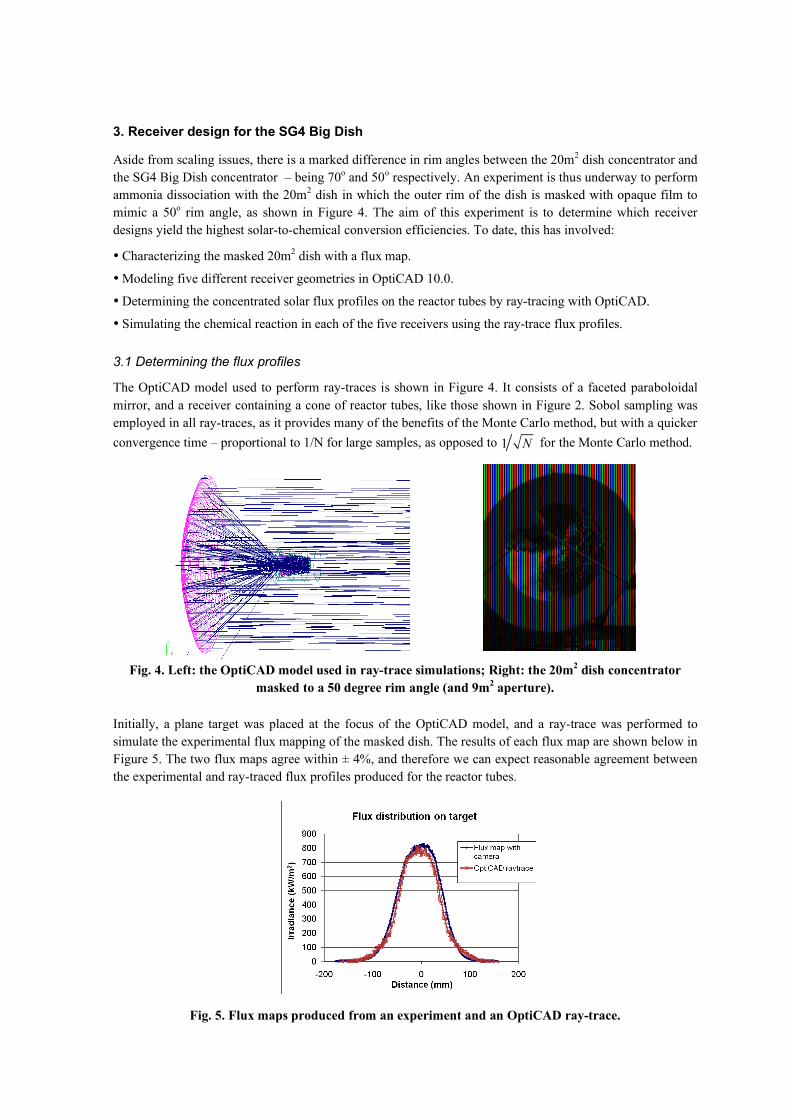
The OptiCAD model used to perform ray-traces is shown in Figure 4. It consists of a faceted paraboloidal mirror, and a receiver containing a cone of reactor tubes, like those shown in Figure 2. Sobol sampling was employed in all ray-traces, as it provides many of the benefits of the Monte Carlo method, but with a quicker convergence time – proportional to 1/N for large samples, as opposed to 1 N for the Monte Carlo method.
Fig. 4. Left: the OptiCAD model used in ray-trace simulations; Right: the 20m2 dish concentrator
masked to a 50 degree rim angle (and 9m2 aperture).
Initially, a plane target was placed at the focus of the OptiCAD model, and a ray-trace was performed to simulate the experimental flux mapping of the masked dish. The results of each flux map are shown below in Figure 5. The two flux maps agree within ± 4%, and therefore we can expect reasonable agreement between the experimental and ray-traced flux profiles produced for the reactor tubes.
Fig. 5. Flux maps produced from an experiment and an OptiCAD ray-trace.
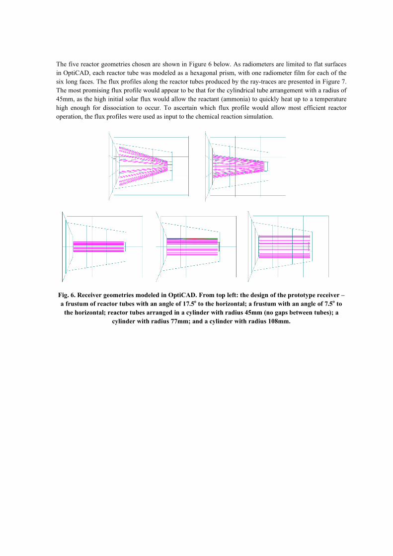
The five reactor geometries chosen are shown in Figure 6 below. As radiometers are limited to flat surfaces in OptiCAD, each reactor tube was modeled as a hexagonal prism, with one radiometer film for each of the six long faces. The flux profiles along the reactor tubes produced by the ray-traces are presented in Figure 7. The most promising flux profile would appear to be that for the cylindrical tube arrangement with a radius of 45mm, as the high initial solar flux would allow the reactant (ammonia) to quickly heat up to a temperature high enough for dissociation to occur. To ascertain which flux profile would allow most efficient reactor operation, the flux profiles were used as input to the chemical reaction simulation.
Fig. 6. Receiver geometries modeled in OptiCAD. From top left: the design of the prototype receiver – a frustum of reactor tubes with an angle of 17.5o to the horizontal; a frustum with an angle of 7.5o to
the horizontal; reactor tubes arranged in a cylinder with radius 45mm (no gaps between tubes); a cylinder with radius 77mm; and a cylinder with radius 108mm.
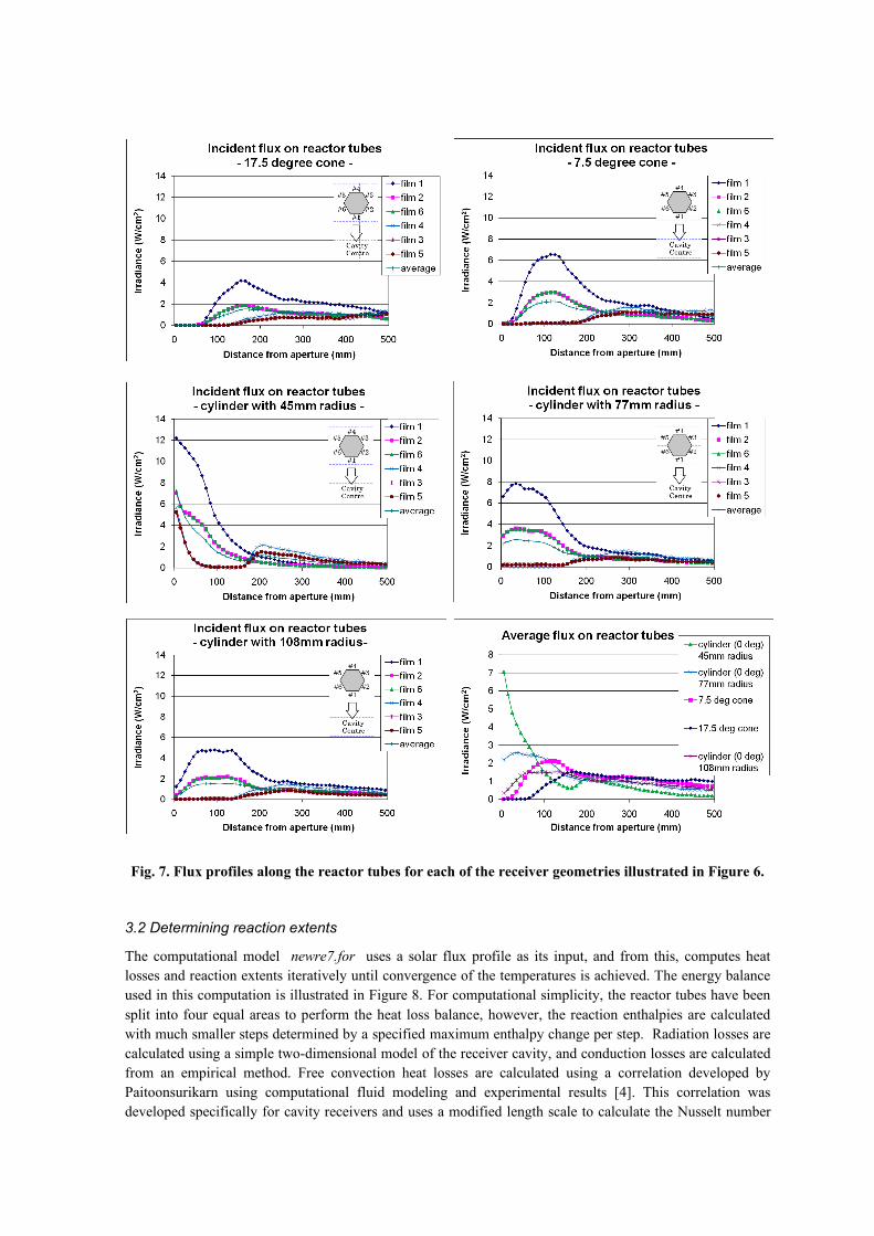
Fig. 7. Flux profiles along the reactor tubes for each of the receiver geometries illustrated in Figure 6.
3.2 Determining reaction extents
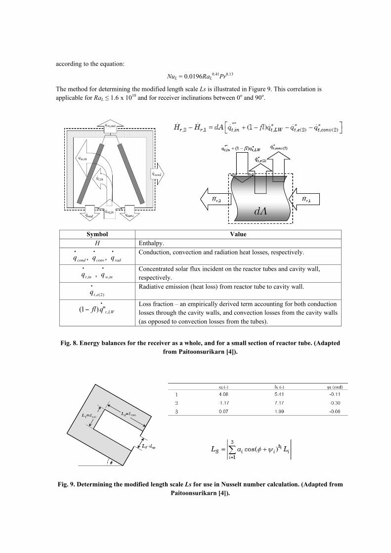
The computational model newre7.for uses a solar flux profile as its input, and from this, computes heat losses and reaction extents iteratively until convergence of the temperatures is achieved. The energy balance used in this computation is illustrated in Figure 8. For computational simplicity, the reactor tubes have been split into four equal areas to perform the heat loss balance, however, the reaction enthalpies are calculated with much smaller steps determined by a specified maximum enthalpy change per step. Radiation losses are calculated using a simple two-dimensional model of the receiver cavity, and conduction losses are calculated from an empirical method. Free convection heat losses are calculated using a correlation developed by Paitoonsurikarn using computational fluid modeling and experimental results [4]. This correlation was developed specifically for cavity receivers and uses a modified length scale to calculate the Nusselt number
according to the equation:
NuL = 0.0196RaL0.41Pr0.13
The method for determining the modified length scale Ls is illustrated in Figure 9. This correlation is applicable for RaL ≤ 1.6 x 10¹⁰ and for receiver inclinations between 0o and 90o.
Symbol Value H Enthalpy.
, , cond conv radq q q• • •
Conduction, convection and radiation heat losses, respectively.
, , ,
t in w inq q• •
Concentrated solar flux incident on the reactor tubes and cavity wall, respectively.
, (2)t eq•
Radiative emission (heat loss) from reactor tube to cavity wall.
,(1 ) "t LWfl q•
! Loss fraction – an empirically derived term accounting for both conduction losses through the cavity walls, and convection losses from the cavity walls (as opposed to convection losses from the tubes).
Fig. 8. Energy balances for the receiver as a whole, and for a small section of reactor tube. (Adapted from Paitoonsurikarn [4]).
Fig. 9. Determining the modified length scale Ls for use in Nusselt number calculation. (Adapted from Paitoonsurikarn [4]).
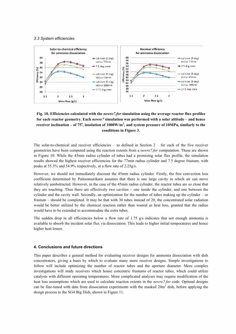
3.3 System efficiencies
Fig. 10. Efficiencies calculated with the newre7.for simulation using the average reactor flux profiles for each reactor geometry. Each newre7 simulation was performed with a solar altitude – and hence receiver inclination – of 75o, insolation of 1000W/m2, and system pressure of 10MPa, similarly to the
conditions in Figure 3.
The solar-to-chemical and receiver efficiencies – as defined in Section 2 – for each of the five receiver geometries have been computed using the reaction extents from a newre7.for computation. These are shown in Figure 10. While the 45mm radius cylinder of tubes had a promising solar flux profile, the simulation results showed the highest receiver efficiencies for the 77mm radius cylinder and 7.5 degree frustum, with peaks at 55.3% and 54.9% respectively, at a flow rate of 2.25g/s.
However, we should not immediately discount the 45mm radius cylinder. Firstly, the free convection loss coefficient determined by Paitoonsurikarn assumes that there is one large cavity in which air can move relatively unobstructed. However, in the case of the 45mm radius cylinder, the reactor tubes are so close that they are touching. Thus there are effectively two cavities – one inside the cylinder, and one between the cylinder and the cavity wall. Secondly, an optimization for the number of tubes making up the cylinder – or frustum – should be completed. It may be that with 30 tubes instead of 20, the concentrated solar radiation would be better utilized by the chemical reaction rather than wasted as heat loss, granted that the radius would have to be extended to accommodate the extra tubes.
The sudden drop in all efficiencies below a flow rate of 1.75 g/s indicates that not enough ammonia is available to absorb the incident solar flux via dissociation. This leads to higher initial temperatures and hence higher heat losses.
4. Conclusions and future directions
This paper describes a general method for evaluating receiver designs for ammonia dissociation with dish concentrators, giving a basis by which to evaluate many more receiver designs. Simple investigations to follow will include optimizing the number of reactor tubes and the aperture diameter. More complex investigations will study receivers which house concentric frustums of reactor tubes, which could utilize catalysts with different operating temperatures. More complicated analyses may require modification of the heat loss assumptions which are used to calculate reaction extents in the newre7.for code. Optimal designs can be fine-tuned with data from dissociation experiments with the masked 20m2 dish, before applying the design process to the SG4 Big Dish, shown in Figure 11.
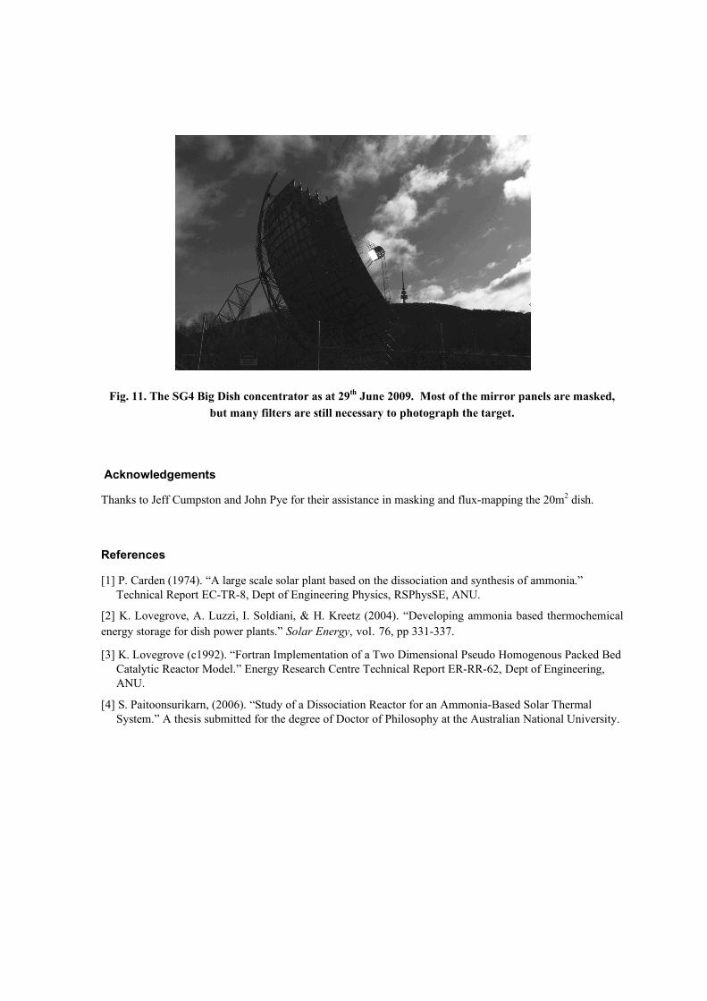
Fig. 11. The SG4 Big Dish concentrator as at 29th June 2009. Most of the mirror panels are masked, but many filters are still necessary to photograph the target.
Acknowledgements
Thanks to Jeff Cumpston and John Pye for their assistance in masking and flux-mapping the 20m2 dish.
References
[1] P. Carden (1974). “A large scale solar plant based on the dissociation and synthesis of ammonia.” Technical Report EC-TR-8, Dept of Engineering Physics, RSPhysSE, ANU.
[2] K. Lovegrove, A. Luzzi, I. Soldiani, & H. Kreetz (2004). “Developing ammonia based thermochemical energy storage for dish power plants.” Solar Energy, vol. 76, pp 331-337.
[3] K. Lovegrove (c1992). “Fortran Implementation of a Two Dimensional Pseudo Homogenous Packed Bed Catalytic Reactor Model.” Energy Research Centre Technical Report ER-RR-62, Dept of Engineering, ANU.
[4] S. Paitoonsurikarn, (2006). “Study of a Dissociation Reactor for an Ammonia-Based Solar Thermal System.” A thesis submitted for the degree of Doctor of Philosophy at the Australian National University.


![TEMPLATE Roads and Streets SCOPE Map extents …...TEMPLATE FOR LOCAL AUTHORITY STREET GUIDANCE Roads and Streets Design Guidance for [ .] SCOPE Map extents and main places within](https://img.pdfslide.us/doc/110x75/5e8989e46dc14c2eb605b611/template-roads-and-streets-scope-map-extents-template-for-local-authority-street.jpg)