Embed Size (px)
Citation preview

i AMDOC-000203 Rev 05 ANCA Motion
AMI5000 Series Touchpad User Manual
AMDOC-000203 Rev 05

AMI5000 Series Touchpad User Manual
ii AMDOC-000203 Rev 05 ANCA Motion
AMI5000 Series Touchpad User Manual
Some Important Links
Related Manuals and Brochures: AMI5000 Touchpad Related Documentation
Related Manuals and Brochures: AMI5000 Remote Pendant Related Documentation
Sales and Support Contact Information
For the latest copy of the manual visit us online Manuals
Some Important References
PMK Manual: Please refer to the latest PMK User Manual (version 9.01 or later)
Document Reference: AMDOC-000203 Rev 05
Effective: 25-10-2017
© ANCA Motion Pty. Ltd.

iii AMDOC-000203 Rev 05 ANCA Motion
Table of Contents
Safety ................................................................................................................................................................. 6 1
General Safety ........................................................................................................................................ 6 1.1
Introduction....................................................................................................................................................... 7 2
Purpose ................................................................................................................................................... 7 2.1
About the AMI5000 Touchpad ................................................................................................................. 7 2.2
Touchpad variant Applicability ................................................................................................................. 8 2.3
PMK Version Applicability ....................................................................................................................... 8 2.4
Terms and Abbreviations ........................................................................................................................ 8 2.5
Product Overview ............................................................................................................................................. 9 3
Introduction ............................................................................................................................................. 9 3.1
Features .................................................................................................................................................. 9 3.2
AMI5000 Touchpad Product Label .......................................................................................................... 9 3.3
Touchpad Overview: Variants ............................................................................................................... 10 3.4
Mechanical Installation .................................................................................................................................. 11 4
Introduction ........................................................................................................................................... 11 4.1
Pre Installation Checks.......................................................................................................................... 11 4.2
Requirements ........................................................................................................................................ 11 4.3
Installation Site ........................................................................................................................ 11 4.3.1
Mounting .................................................................................................................................. 11 4.3.2
Accessory Box ......................................................................................................................... 12 4.3.3
External Interface Cable Assemblies .................................................................................................... 14 4.4
Pivot Variant ............................................................................................................................ 14 4.4.1
Mounting Arm Variant .............................................................................................................. 16 4.4.2
Installation ............................................................................................................................................. 19 4.5
Mounting the Touchpad: Pivot Variant ..................................................................................... 19 4.5.1
Mounting the Touchpad: Mounting Arm Variant ...................................................................... 25 4.5.2
Electrical Installation ...................................................................................................................................... 35 5
Introduction ........................................................................................................................................... 35 5.1
Interface Overview ................................................................................................................................ 36 5.2
AMI5000 Touchpad Board ....................................................................................................... 36 5.2.1
E-Stop and Key Switch Interface Connector ........................................................................... 38 5.2.2
Digital Video Interface Connector ............................................................................................ 41 5.2.3
Customer Machine Chassis Earth Connection ........................................................................ 42 5.2.4
Wiring Diagram ..................................................................................................................................... 43 5.3
Touchpad Wiring: Patch Board Interface ................................................................................. 43 5.3.1
Touchpad Wiring: Customer Machine Chassis Earth: Chassis................................................ 44 5.3.2
Touchpad Wiring: Digital Video Interface ................................................................................ 44 5.3.3
Touchpad Wiring: USB Interface ............................................................................................. 44 5.3.4

Safety
ANCA Motion AMDOC-000203 Rev 05 4
1
Touchpad Wiring: Power Supply ............................................................................................. 44 5.3.5
Touchpad Wiring: Switch Interface .......................................................................................... 45 5.3.6
Touchpad Wiring: E-Stop and Key Switch Interface ................................................................ 45 5.3.7
Touchpad Wiring: Customer Machine Chassis Earth: Rear Panel .......................................... 45 5.3.8
Unit Removal from Customer Machine ......................................................................................................... 46 6
Introduction ........................................................................................................................................... 46 6.1
Site Requirements ................................................................................................................................. 46 6.2
Removal Procedure: Pivot Variant ........................................................................................................ 46 6.3
Removal Procedure: Mounting Arm Variant .......................................................................................... 51 6.4
E-Stop and Key Switch .................................................................................................................................. 58 7
Connection of the E-Stop and Key Switch............................................................................................. 58 7.1
E-Stop Switch Configuration ................................................................................................................. 58 7.2
Key Switch Configuration ...................................................................................................................... 59 7.3
Installation Checklist for the Touchpad ....................................................................................................... 60 8
Introduction ........................................................................................................................................... 60 8.1
Installation Checklist ............................................................................................................................. 60 8.2
Commissioning and Testing.......................................................................................................................... 61 9
Testing/Power-on Checks ..................................................................................................................... 61 9.1
Commissioning Checks ......................................................................................................................... 61 9.2
Operation ........................................................................................................................................................ 63 10
Display Interface ................................................................................................................................... 63 10.1
External USB Interface .......................................................................................................................... 63 10.2
Audio Interface ...................................................................................................................................... 63 10.3
Switch Interface ..................................................................................................................................... 63 10.4
E-Stop and Key Switch Interface ........................................................................................................... 65 10.5
E-Stop ................................................................................................................................. 65 10.5.1
Key Switch .......................................................................................................................... 65 10.5.2
Touchpad Fault Diagnostics.......................................................................................................................... 66 11
Introduction ........................................................................................................................................... 66 11.1
Touchpad Board LED Indicator States .................................................................................................. 66 11.2
Power Supply Indicator ....................................................................................................... 67 11.2.1
USB Port Indicators ............................................................................................................. 67 11.2.2
Audio LED Indicators .......................................................................................................... 68 11.2.3
Touchpad Display ................................................................................................................................. 69 11.3
Display ................................................................................................................................ 69 11.3.1
Multi-point Touchpad Interface ............................................................................................ 69 11.3.2
Multi-point Touchpad Interface: Calibration Procedure ....................................................... 69 11.3.3
Standards Conformity .................................................................................................................................... 70 12
CE Compliance ..................................................................................................................................... 70 12.1
FCC Marking ......................................................................................................................................... 71 12.2

Safety
ANCA Motion AMDOC-000203 Rev 05 5
1
Specifications ................................................................................................................................................. 72 13
Electrical ................................................................................................................................................ 72 13.1
Power Supply ...................................................................................................................... 72 13.1.1
Switch Interface ................................................................................................................... 72 13.1.2
E-Stop and Key Switch Interface ......................................................................................... 73 13.1.3
Audio Interface .................................................................................................................... 73 13.1.4
Video Interface .................................................................................................................... 73 13.1.5
Touch Interface ................................................................................................................... 74 13.1.6
USB Interface ...................................................................................................................... 74 13.1.7
Mechanical ............................................................................................................................................ 74 13.2
Physical ............................................................................................................................... 74 13.2.1
Environmental ..................................................................................................................... 75 13.2.2
AMI5000 Touchpad Overall Dimensions ............................................................................................... 75 13.3
Fitment Dimensions for Typical Machine: Pivot Variant ........................................................................ 76 13.4
Upper Pivot Bracket Dimensions: Pivot Variant .................................................................................... 77 13.5
Lower Pivot Mounting Details: Pivot Variant .......................................................................................... 77 13.6
Rolec Mounting Arm Specifications: Mounting Arm Variant .................................................................. 78 13.7
Accessories .................................................................................................................................................... 79 14
Introduction ........................................................................................................................................... 79 14.1
Recommended Power Interface Connector .......................................................................................... 79 14.2
Recommended Switch Interface Connector .......................................................................................... 79 14.3
Recommended E-Stop and Key Switch Interface Connectors .............................................................. 79 14.4
Recommended Connector Crimps ........................................................................................................ 80 14.5
Cable Assemblies ................................................................................................................................. 80 14.6
Adaptor Cable Assemblies .................................................................................................................... 80 14.7
Demonstration Wiring Loom .................................................................................................................. 80 14.8
Mounting Arm Variant Accessories ....................................................................................................... 81 14.9
Additional Information ................................................................................................................................... 82 15
Display Cleaning ................................................................................................................................... 82 15.1
Maintenance and Repairs ..................................................................................................................... 82 15.2
Product, Sales and Service Enquiries ................................................................................................... 82 15.3
Feedback .............................................................................................................................................. 83 15.4

Safety
ANCA Motion AMDOC-000203 Rev 05 6
1
Safety 1
General Safety 1.1
Warning: To prevent possible accidents or injury, ensure you read and understand this manual before
commencing installation or commissioning work on the AMI5000 Touchpad.
This manual and the warnings attached to the Touchpad only highlight hazards that can be predicted by ANCA Motion. Be aware they do not cover all possible hazards.
ANCA Motion shall not be responsible for any accidents caused by the misuse or abuse of the device by the operator.
Safe operation of these devices is your own responsibility. By taking note of the safety precautions, tips and warnings in this manual you can help to ensure your own safety and the safety of those around you.
The following points must be understood and adhered to at all times:
Equipment operators must read the user manual carefully and make sure of the correct procedure before operating the Touchpad.
If two or more persons are working together, establish signals so that they can communicate to confirm safety before proceeding to another step.
Always make sure there are no obstacles or people near the devices during installation and or operation. Be aware of your environment and what is around you.
Take precautions to ensure that your clothing, hair or personal effects (such as jewellery) cannot become entangled in the equipment.
Do not remove the rear cover to access the inside of the Touchpad unless authorized
Do not turn on any of the equipment without all safety features in place and known to be functioning correctly.
Never touch any exposed wiring, connections or fittings while the equipment is in operation.
Do not apply any excessive mechanical force to the Touchpad, which may cause malfunction or failure.
Keep the vicinity of the Touchpad clean and tidy.
Never attempt cleaning or inspection during machine operation.
ESD Safe Installation procedures should be followed.
Only suitably qualified personnel should install, operate, repair and/or replace this equipment.
Be aware of the closest First Aid station.
Ensure all external wiring is clearly labelled. This will assist you and your colleagues in identifying possible electrical safety hazards.
Clean or inspect the equipment only after isolating all power sources.
Install cables according to local legislation and regulations as applicable.

Introduction
ANCA Motion AMDOC-000203 Rev 05 7
2
Introduction 2
Purpose 2.1
This manual provides the required information for installing, commissioning and operating the AMI5000 Touchpad. It has been written specifically to meet the needs of qualified engineers, tradespersons, technicians and operators.
Every effort has been made to simplify the procedures applicable to the Touchpad in this manual. However, given the sometimes complex nature of the information, some prior knowledge of associated units, their configuration and or programming is assumed.
About the AMI5000 Touchpad 2.2
The AMI5000 Touchpad is used as a Human Machine Interface (HMI), which interfaces directly with the ANCA Motion Control System Software to support fast and flexible access for real-time control, in conjunction with the Handheld Remote Pendant. The Touchpad is designed to mount directly onto the Customer Machine and to connect directly to the (internal) Customer Machine CNC. The Touchpad is available in two mounting variants to support a Pivot or Mounting Arm format.
Please refer to 3.2 Features for more details of the available features.
Figure 2-1 Touchpad: Front View - Pivot
Figure 2-2 Touchpad: Front View – Mounting Arm
Introduction
ANCA Motion AMDOC-000203 Rev 05 8
2
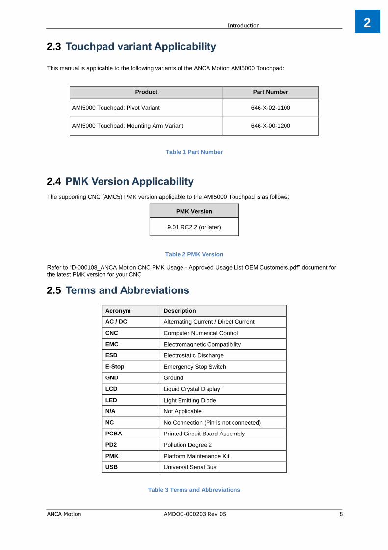
Touchpad variant Applicability 2.3
This manual is applicable to the following variants of the ANCA Motion AMI5000 Touchpad:
Product Part Number
AMI5000 Touchpad: Pivot Variant 646-X-02-1100
AMI5000 Touchpad: Mounting Arm Variant 646-X-00-1200
Table 1 Part Number
PMK Version Applicability 2.4
The supporting CNC (AMC5) PMK version applicable to the AMI5000 Touchpad is as follows:
PMK Version
9.01 RC2.2 (or later)
Table 2 PMK Version
Refer to “D-000108_ANCA Motion CNC PMK Usage - Approved Usage List OEM Customers.pdf” document for the latest PMK version for your CNC
Terms and Abbreviations 2.5
Acronym Description
AC / DC Alternating Current / Direct Current
CNC Computer Numerical Control
EMC Electromagnetic Compatibility
ESD Electrostatic Discharge
E-Stop Emergency Stop Switch
GND Ground
LCD Liquid Crystal Display
LED Light Emitting Diode
N/A Not Applicable
NC No Connection (Pin is not connected)
PCBA Printed Circuit Board Assembly
PD2 Pollution Degree 2
PMK Platform Maintenance Kit
USB Universal Serial Bus
Table 3 Terms and Abbreviations

Product Overview
ANCA Motion AMDOC-000203 Rev 05 9
3
Product Overview 3
Introduction 3.1
This chapter introduces the reader to the Touchpad by providing the following information:
Features
Label configuration
Product overview
Features 3.2
The ANCA Motion AMI5000 Touchpad has the following features:
19 inch LCD Display with resolution of 1024 x 1280 (H x V) in Portrait Mode
Integrated Multipoint Touchpad Interface
Variants to suit a Pivot or Mounting Arm mechanical mounting to allow flexible positioning
Five dedicated Machine Operation Switches with LED Feedback
Emergency Stop Switch
Key Switch
Three external USB Type A Ports for User supplied equipment
Integrated audio system for User Feedback
IP53 Protection Rating
AMI5000 Touchpad Product Label 3.3
The Touchpad is marked with a Product Label; the label configuration is shown below:
Figure 3-1 Touchpad Label
For any warranty work to be undertaken this label must be readable and undamaged. Care should be taken to record these numbers in a separate register in the event of damage or loss. The label can be found on the bottom face of the product.
Note: Do not under any circumstances tamper with this label. Your warranty may be void if the label is damaged.

Product Overview
ANCA Motion AMDOC-000203 Rev 05 10
3
Touchpad Overview: Variants 3.4
Figure 3-2 Overview Image of Touchpad – Pivot
Figure 3-3 Overview Image of Touchpad – Mounting Arm
These images show the location of the different controls on the AMI5000 Touchpad (refer to 3.2 Features). The Touchpad interfaces with the CNC Control System through the Touchpad Interface Connectors which can be accessed by removing the Rear Cover of the Unit (see section 5 Electrical Installation for more information)
.
External USB Ports (x3)
Key Switch
Palm Support Rest
Tactile Switches (x5)
Touch Screen
Upper Pivot Bush
Lower Pivot Mechanism
E-Stop
Keyboard Tray
Remote Pendant, Bracket and Cradle
Mounting Arm (User supplied)
Mechanical Installation
ANCA Motion AMDOC-000203 Rev 05 11
4
Mechanical Installation 4
Introduction 4.1
This chapter describes mounting the Touchpad:
Pre installation checks
Installation site requirements
External Interface Cable Assemblies
Mounting procedure
Pre Installation Checks 4.2
Prior to installing the panel, please refer to section 3.3 AMI5000 Touchpad Product Label to ensure you have the correct variant for the application.
Check that the Touchpad was not damaged during transport. Please notify your dealer immediately of damage, prior to beginning installation procedures.
Requirements 4.3
Installation Site 4.3.1
The following is a set of requirements on the installation site. Failure to follow these instructions may result in failure or degraded operation:
The Touchpad must only be installed indoors.
Refer to section 4.3.2 Mounting for the correct installation process.
The safety precautions outlined in section 1 Safety must be understood and adhered to.
The operating environment must not contain corrosive substances, metal particles, dust,
condensation, flammable substances or gases.
The Touchpad must not be installed in an environment in which the pollution degree exceeds PD2.
ESD Safe Installation procedures should be followed.
Ensure that the Power Supply to the Machine is in an OFF condition.
Mounting 4.3.2
The Touchpad is designed to mount directly onto the Customer Machine.
The Pivot variant of the Touchpad rotates about a vertical axis with Upper and Lower Pivot components; the Touchpad can only be installed in a vertical orientation.
The Mounting Arm Variant of the Touchpad fits to a (user supplied) Mounting Arm via the Rear Panel.
The Touchpad is supplied with the Rear Cover partially attached to ease the delivery and installation process.
Ensure that the hardware is tightened to the correct torque settings as specified in the Mechanical Installation procedure.
Mechanical Installation
ANCA Motion AMDOC-000203 Rev 05 12
4
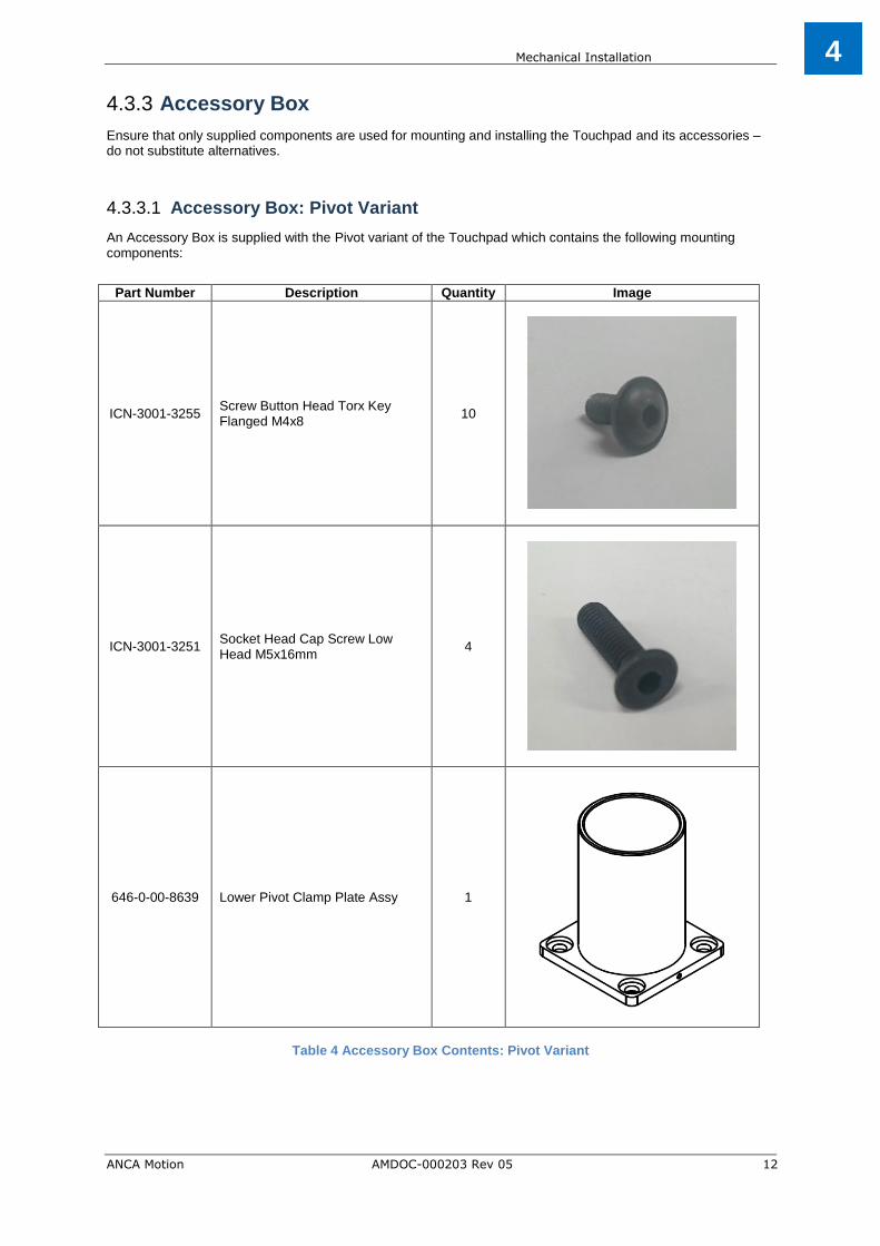
Accessory Box 4.3.3
Ensure that only supplied components are used for mounting and installing the Touchpad and its accessories – do not substitute alternatives.
Accessory Box: Pivot Variant 4.3.3.1
An Accessory Box is supplied with the Pivot variant of the Touchpad which contains the following mounting components:
Part Number Description Quantity Image
ICN-3001-3255 Screw Button Head Torx Key Flanged M4x8
10
ICN-3001-3251 Socket Head Cap Screw Low Head M5x16mm
4
646-0-00-8639 Lower Pivot Clamp Plate Assy 1
Table 4 Accessory Box Contents: Pivot Variant

Mechanical Installation
ANCA Motion AMDOC-000203 Rev 05 13
4
Accessory Bag: Mounting Arm Variant 4.3.3.2
An Accessory Bag is supplied with the Mounting Arm Variant of the Touchpad which contains the following mounting components:
Part Number Description Quantity Image
ICN-3001-3255 Screw Button Head Torx Key Flanged M4x8
10
ICN-3001-3289 SCREW BUTTON HEAD CAP M6x14mm
4
ICN-3004-0106 WASHER FLAT M6 O.D 12mm 4
ICN-3001-0361 COUNTERSUNK SOCKET SET SCREW M6x16mm
3
Table 5 Accessory Bag Contents: Mounting Arm Variant
Mechanical Installation
ANCA Motion AMDOC-000203 Rev 05 14
4
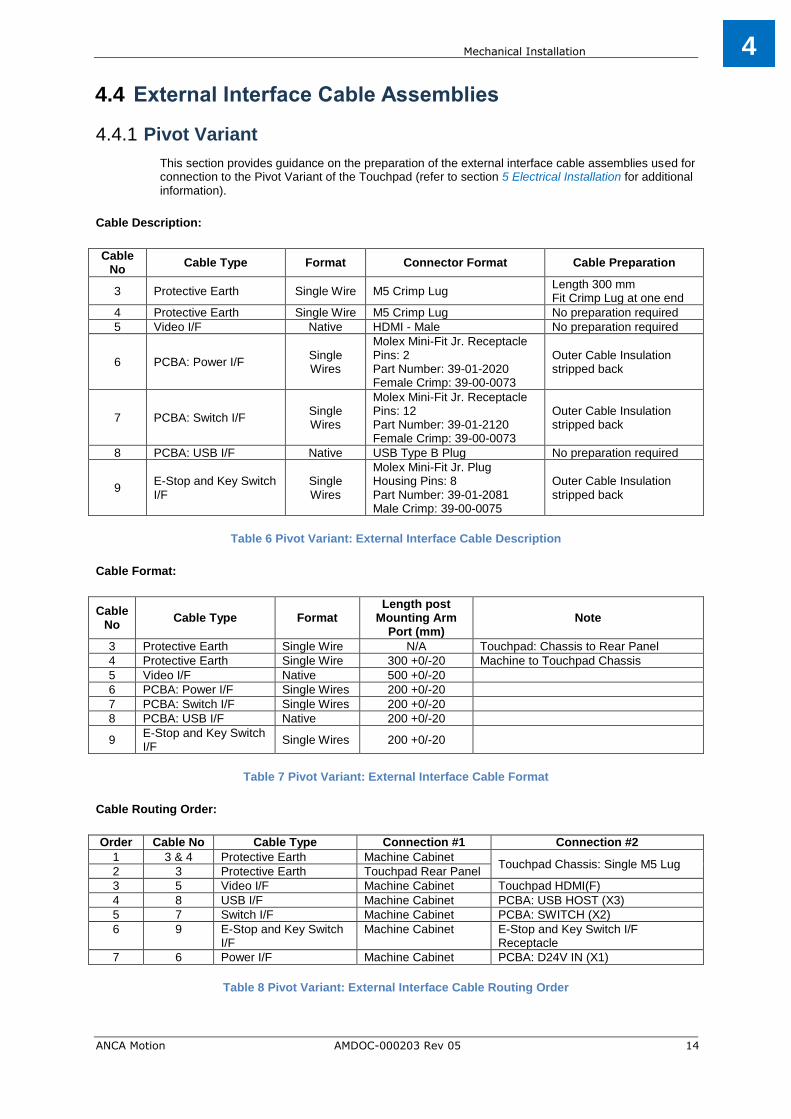
External Interface Cable Assemblies 4.4
Pivot Variant 4.4.1
This section provides guidance on the preparation of the external interface cable assemblies used for connection to the Pivot Variant of the Touchpad (refer to section 5 Electrical Installation for additional information).
Cable Description:
Cable No
Cable Type Format Connector Format Cable Preparation
3 Protective Earth Single Wire M5 Crimp Lug Length 300 mm Fit Crimp Lug at one end
4 Protective Earth Single Wire M5 Crimp Lug No preparation required
5 Video I/F Native HDMI - Male No preparation required
6 PCBA: Power I/F Single Wires
Molex Mini-Fit Jr. Receptacle Pins: 2 Part Number: 39-01-2020 Female Crimp: 39-00-0073
Outer Cable Insulation stripped back
7 PCBA: Switch I/F Single Wires
Molex Mini-Fit Jr. Receptacle Pins: 12 Part Number: 39-01-2120 Female Crimp: 39-00-0073
Outer Cable Insulation stripped back
8 PCBA: USB I/F Native USB Type B Plug No preparation required
9 E-Stop and Key Switch I/F
Single Wires
Molex Mini-Fit Jr. Plug Housing Pins: 8 Part Number: 39-01-2081 Male Crimp: 39-00-0075
Outer Cable Insulation stripped back
Table 6 Pivot Variant: External Interface Cable Description
Cable Format:
Cable No
Cable Type Format Length post
Mounting Arm Port (mm)
Note
3 Protective Earth Single Wire N/A Touchpad: Chassis to Rear Panel
4 Protective Earth Single Wire 300 +0/-20 Machine to Touchpad Chassis
5 Video I/F Native 500 +0/-20
6 PCBA: Power I/F Single Wires 200 +0/-20
7 PCBA: Switch I/F Single Wires 200 +0/-20
8 PCBA: USB I/F Native 200 +0/-20
9 E-Stop and Key Switch I/F
Single Wires 200 +0/-20
Table 7 Pivot Variant: External Interface Cable Format
Cable Routing Order:
Order Cable No Cable Type Connection #1 Connection #2
1 3 & 4 Protective Earth Machine Cabinet Touchpad Chassis: Single M5 Lug
2 3 Protective Earth Touchpad Rear Panel
3 5 Video I/F Machine Cabinet Touchpad HDMI(F)
4 8 USB I/F Machine Cabinet PCBA: USB HOST (X3)
5 7 Switch I/F Machine Cabinet PCBA: SWITCH (X2)
6 9 E-Stop and Key Switch I/F
Machine Cabinet E-Stop and Key Switch I/F Receptacle
7 6 Power I/F Machine Cabinet PCBA: D24V IN (X1)
Table 8 Pivot Variant: External Interface Cable Routing Order

Mechanical Installation
ANCA Motion AMDOC-000203 Rev 05 15
4
Ancillary Components:
Part Number Description Quantity Note
ICN-3083-0002 CABLE TIE 150 mm CT143 3 Cable Tie position A
Table 9 Pivot Variant: External Interface Cable Ancillary Components
Reference: Internal Touchpad Interface Connectors:
Figure 4-1 Pivot Variant: Internal Interface Connector Reference

Mechanical Installation
ANCA Motion AMDOC-000203 Rev 05 16
4
Mounting Arm Variant 4.4.2
This section provides guidance on the preparation of the external interface cable assemblies used for connection to the Mounting Arm Variant of the Touchpad (refer to section 5 Electrical Installation for
additional information).
Cable Description:
Cable No
Cable Type Format Connector Format Cable Preparation
1 Patch Panel: Safety I/F Native Phoenix: FK-MCP 1,5/10-ST-3,81
Outer Cable Insulation stripped back
2 Patch Panel: EtherCAT Native RJ45 8P8C modular connector
No preparation required
3 Protective Earth Single Wire M5 Crimp Lug Length 300 mm Fit Crimp Lug at one end
4 Protective Earth Single Wire M5 Crimp Lug No preparation required
5 Video I/F Native HDMI - Male No preparation required
6 PCBA: Power I/F Single Wires
Molex Mini-Fit Jr. Receptacle Pins: 2 Part Number: 39-01-2020 Female Crimp: 39-00-0073
Outer Cable Insulation stripped back
7 PCBA: Switch I/F Single Wires
Molex Mini-Fit Jr. Receptacle Pins: 12 Part Number: 39-01-2120 Female Crimp: 39-00-0073
Outer Cable Insulation stripped back
8 PCBA: USB I/F Native USB Type B Plug No preparation required
9 E-Stop and Key Switch I/F
Single Wires
Molex Mini-Fit Jr. Plug Housing Pins: 10 Part Number: 39-01-2101 Male Crimp: 39-00-0075
Outer Cable Insulation stripped back
Table 10 Mounting Arm Variant: External Interface Cable Description
Cable Format:
Cable No
Cable Type Format Length post
Mounting Arm Port (mm)
Note
1 Patch Panel: Safety I/F Native 300 +0/-20
2 Patch Panel: EtherCAT Native 300 +0/-20
3 Protective Earth Single Wire N/A Touchpad: Chassis to Rear Panel
4 Protective Earth Single Wire 300 +0/-20 Machine to Touchpad Chassis
5 Video I/F Native 500 +0/-20
6 PCBA: Power I/F Single Wires 350 +0/-20
7 PCBA: Switch I/F Single Wires 350 +0/-20
8 PCBA: USB I/F Native 300 +0/-20
9 E-Stop and Key Switch I/F
Single Wires 300 +0/-20
Table 11 Mounting Arm Variant: External Interface Cable Format

Mechanical Installation
ANCA Motion AMDOC-000203 Rev 05 17
4
Cable Routing Order:
Order Cable No Cable Type Connection #1 Connection #2
1 1 Patch Panel: Safety I/F Machine Cabinet Patch Panel: X2
2 2 Patch Panel: EtherCAT Machine Cabinet Patch Panel: X3
3 3 Protective Earth Touchpad Rear Panel Touchpad Chassis: Single M5 Lug
4 3 & 4 Protective Earth Machine Cabinet
5 5 Video I/F Machine Cabinet Touchpad HDMI(F)
6 6 Power I/F Machine Cabinet PCBA: D24V IN (X1)
7 7 Switch I/F Machine Cabinet PCBA: SWITCH (X2)
8 8 USB I/F Machine Cabinet PCBA: USB HOST (X3)
9 9 E-Stop and Key Switch I/F
Machine Cabinet E-Stop and Key Switch I/F Receptacle
Table 12 Mounting Arm Variant: External Interface Cable Routing Order
Ancillary Components:
Part Number Description Quantity Note
ICN-3083-0002 CABLE TIE 150 mm CT143 3 Cable Tie positions A, B and C
Table 13 Mounting Arm Variant: External Interface Cable Ancillary Components
Reference: Internal Touchpad Interface Connectors:
Figure 4-3 Mounting Arm Variant: Internal Interface Connector Reference

Mechanical Installation
ANCA Motion AMDOC-000203 Rev 05 18
4
Reference: Cable Numbers:
Figure 4-4 Mounting Arm Variant: Cable Number Reference

Mechanical Installation
ANCA Motion AMDOC-000203 Rev 05 19
4
Installation 4.5
Mounting the Touchpad: Pivot Variant 4.5.1
Tools Required:
Description Quantity Note
Torque Wrench 1 Torque function required for assembly
2.5 mm Hex Driver 1 Installing the Rear Panel to the Touchpad
3.0 mm Hex Driver 1 Mounting the Lower Pivot mechanism to the Customer Machine
8 mm Socket 1 Tightening the M5 Earth Stud Nut
Tightening the Hose Clamp onto the Pivot Bush
Table 14 Mounting the Touchpad: Tools Required
Parts Required:
Part Number Description Quantity Note
646-X-02-1100 AMI5000 Touchpad 1 Unit to be installed onto the Machine
ICN-3001-3255 Screw Button Head Torx Key Flanged M4x8
12 Loosely supplied with 646-X-02-1100 (partially installed on 646-X-02-1100)
ICN-3001-3251 Socket Head Cap Screw Low Head M5x16mm
4 Loosely supplied with 646-X-02-1100
646-0-00-8639 Lower Pivot Clamp Plate Assy 1 Loosely supplied with 646-X-02-1100
ICN-3001-0444 Nyloc Nut M5 2 Partially installed on 646-X-02-1100
ICN-3048-0015 Hose Clamp Worm Drive Dia 30-45mm
1 Partially installed on 646-X-02-1100
N/A
Rear Panel Chassis Earth Cable 1 User supplied
646-0-00-8717 AMI5000 Touchpad Adaptor Cable 1 Supplied separately (use as required)
ICN-3083-0004 Adhesive Cable Tie Holders 2 Internal cable management
ICN-3083-0001 Plastic Cable Ties 2 Internal cable management
Table 15 Mounting the Touchpad: Parts Required
Tightening Torque:
Part Number Description Torque (Nm)
ICN-3001-3255 Screw Button Head Torx Key Flanged M4x8 0.3
ICN-3001-3251 Socket Head Cap Screw Low Head M5x16mm 2.0
ICN-3001-0444 Nyloc Nut M5 1.0
ICN-3048-0015 Hose Clamp Worm Drive Diameter 30-45 mm 1.0
Table 16 Mounting the Touchpad: Tightening Torque

Mechanical Installation
ANCA Motion AMDOC-000203 Rev 05 20
4
Installation Method:
Step Description Images
1 Ensure that the Power Supply to the Machine is in an OFF condition
2
Carefully feed the Machine cables through the Lower Pivot Clamp Plate Assembly in the following order: Digital Video Interface (Cable 5) Switch Interface (Cable 7) E-Stop and Key Switch Interface (Cable 9) Power Interface (Cable 6) USB Interface (Cable 8) Machine Chassis Earth Interface (Cable 4)
Ensure the Machine cables have sufficient length to satisfy the tail lengths detailed in Table 7 Pivot Variant: External Interface Cable Format.
3
After all the cables have been fed through, fit the Lower Pivot Clamp Plate Assembly to the ledge of the Customer Machine by tightening the four M5 SHCS screws (ICN-3001-3251) to 2 Nm. Note: When the Lower Pivot Clamp Plate Assembly is fitted to the ledge, ensure that the small pin that is evident on this plate is placed towards the rear as shown.
4
Remove the Rear Panel from the Touchpad to expose the internal structure. Safely store the Rear Panel and screws until later in the installation process.
5
Remove the Upper Pivot Bracket from the Customer Machine (if fitted). Safely store these parts until later in the installation process.
6
Carefully feed the Machine cables through the hole opening in the Touchpad located in the lower right corner (as viewed from the rear) in the following order: Digital Video Interface (Cable 5) Switch Interface (Cable 7) E-Stop and Key Switch Interface (Cable 9) Power Interface (Cable 6) USB Interface (Cable 8) Machine Chassis Earth Interface (Cable 4)

Mechanical Installation
ANCA Motion AMDOC-000203 Rev 05 21
4
Step Description Images
7
Carefully lower the Touchpad unit over the Lower Pivot Clamp Plate Assembly. Ensure that the Hose Clamp is centrally located between the guided undercuts on the plastic bush. Tighten the nut on the Hose Clamp as shown to 1 Nm.
8
Guide the pin from the Upper Pivot Bracket into the bush opening that is available on the upper chassis of the Touchpad. Place the Upper Pivot Bracket back onto the Customer Machine. Note: Check that there is a small gap between the Upper Pivot Bracket and the Touchpad chassis.
9
Connect the Machine Chassis Earth Cable (#4) and the Rear Panel Chassis Earth Cable (#3 - supplied by the end user) to the Earth Stud located on the bottom of the Touchpad Main Chassis as shown. Ensure the two Earth Cable terminals are located between a Flat Washer and the M5 Nut on the Earth Stud and tighten the Nut to a torque of 1 Nm (refer to section 5.3 for further details). Also ensure that that the Protective Earth sticker is not obstructed.
10A
Connect the Customer Machine Interface Cables to the associated internal Touchpad interfaces (refer to section 5.3 for further details):
Digital Video (#5): HDMI Connector

Mechanical Installation
ANCA Motion AMDOC-000203 Rev 05 22
4
Step Description Images
10B
USB Interface (#8): PCBA X3
10C
Switch Interface (#7): PCBA X2)
E-Stop and Key Switch Interface (#9)
10D
Power Supply (#6): PCBA X1
11
Place the Touchpad Rear Panel on a Support close to the rear of the Main Chassis. Connect the loose end of the Earth Cable (#3) from the Main Chassis to the Rear Panel Earth Stud as shown. Ensure the Earth Cable is located between the Flat Washer and the Nut on the Earth Stud and tighten the Nut to a torque of 1 Nm (refer to section 5.3 for further details).

Mechanical Installation
ANCA Motion AMDOC-000203 Rev 05 23
4
Step Description Images
12
Secure the Rear Panel to the Main Chassis using twelve screws (ICN-3001-3255) with a torque setting of 0.3 Nm. Tip: Secure the diagonal screws in first to locate the panel, then fit and tighten the remaining screws.
13
Place the Touchpad Key into the Key Switch (store the spare Key in a secure location).
14
Confirm the Rear Bump Stop prevents the Touchpad touching the Machine Chassis when the Touchpad is in the fully recessed position.
15
Confirm that the Touchpad rotates freely with a degree of resistance about a vertical axis defined by the Upper and Lower Pivot components.

Mechanical Installation
ANCA Motion AMDOC-000203 Rev 05 24
4
Figure 4-1 Typical installation of the AMI5000 Touchpad on a Customer Machine (also showing the range
of rotation)

Mechanical Installation
ANCA Motion AMDOC-000203 Rev 05 25
4
Mounting the Touchpad: Mounting Arm Variant 4.5.2
Tools Required:
Description Quantity Note
Torque Wrench 1 Torque function required for assembly
2.5 mm Hex Driver 1 Installing the Rear Panel to the Touchpad
3.0 mm Hex Driver 1
Tightening the Keyboard Tray to the chassis
Tightening the Cradle Bracket to the chassis
Tightening the Shipping Brackets to the chassis
4.0 mm Hex Driver 1 Tightening the Mounting Arm to the Rear Panel
Tightening the Cradle to the Cradle Bracket
Table 17 Mounting the Touchpad: Tools Required
Parts Required:
Part Number Description Quantity Note
646-X-00-1200 AMI5000 Touchpad 1 Unit to be installed onto the Machine
142.280.XXX XXX = cut length
Desk Coupling N, profiPLUS 50 1 Part to be ordered separately from Rolec
ICN-3001-3255 Screw Button Head Torx Key Flanged M4x8
12 Loosely supplied with 646-X-00-1200 (also partially installed)
ICN-3001-3289 SCREW BUTTON HEAD CAP M6x14 mm
4 Loosely supplied with 646-X-00-1200
ICN-3004-0106 WASHER FLAT M6 O.D 12 mm 4 Loosely supplied with 646-X-00-1200
ICN-3001-0361 C'SUNK SOCKET SET SCREW M6x16 mm
3 Loosely supplied with 646-X-00-1200
N/A
Rear Panel Chassis Earth Cable 1 User supplied
ICN-3083-0004 Adhesive Cable Tie Holders As Required Internal cable management
ICN-3083-0001 Plastic Cable Ties As Required Internal cable management
Table 18 Mounting the Touchpad: Parts Required
Tightening Torque:
Part Number Description Torque (Nm)
ICN-3001-3255 Screw Button Head Torx Key Flanged M4x8 0.6
ICN-3001-3289 SCREW BUTTON HEAD CAP M6x14 mm 4.0 - 4.5
ICN-3001-0444 Nyloc Nut M5 1.0
ICN-3001-0361 COUNTERSUNK SOCKET SET SCREW M6x16 mm N/A
ICN-3001-3288 SCREW BUTTON HEAD CAP M5x8 mm 1.5
Table 19 Mounting the Touchpad: Tightening Torque

Mechanical Installation
ANCA Motion AMDOC-000203 Rev 05 26
4
Installation Method:
Step Description Images
1 Ensure that the Power Supply to the Machine is in an OFF condition
2
Carefully feed the Machine cables through the Mounting Arm that is connected to the Machine :
1) Digital Video Interface 2) Switch Interface 3) E-Stop and Key Switch Interface 4) Power Interface 5) USB Interface 6) Machine Chassis Earth Interface 7) Patch Board Interface
Ensure the Machine cables have sufficient length to satisfy the tail lengths detailed in Table 11 Mounting Arm Variant: External Interface Cable Format.
3
Fit the Rear Panel Assembly to the Mounting Arm by tightening the four M6 screws to 4.0 - 4.5 Nm. Ensure that the flat washers are fitted between the screw head and the flat panel as shown. Note: The screw holes in the Rear Panel are slotted to allow small adjustments (if required) to the overall orientation.
4
Check and confirm the grooming of the cables exiting from the Mounting Arm Port. Note that Cable 3 (Protective Earth I/F: Rear Panel to Chassis) is locally routed within the Touchpad Chassis and does not exit from the Mounting Arm Port All Cables should have a tail length of 300 +0/-20 mm, excluding Cable 5 (Video I/F) which requires a tail length of 500 +0/-20 mm, and Cables 6 and 7 (Power and Switch I/F) which require a tail length of 350 +0/-20 mm The Outer Cable Insulation should be stripped back (and secured with Heat Shrink) on the following Cables to match the tail length of 300 mm: 1: Patch Panel Safety I/F 6: Power I/F 7: Switch I/F 9: E-Stop and Key Switch I/F The relevant termination connectors should be fitted to each Cable.

Mechanical Installation
ANCA Motion AMDOC-000203 Rev 05 27
4
Step Description Images
5
Connect Cable 1 to the Patch Panel Safety Interface (X2).
6
Connect Cable 2 to the Patch Panel EtherCAT Interface (X3).
7
Connect Cable 3 to the Touchpad Rear Panel Protective Earth Stud using an M5 Crimp Lug. Ensure the Crimp Lug is located between the Flat Washer and the Nut on the Earth Stud (refer to section 5.3 Wiring Diagram for further details). Orientate the Crimp Lug to face towards the Mounting Arm. Tighten the Nut to a torque of 1 Nm. The other end of Cable 3 will not be connected (NC) at this stage.
8
Rotate the Mounting Arm joint so that the Rear Panel of the Touchpad is in a vertical orientation. Lock the Mounting Arm joint so it does not move prior to mounting. Lift the Touchpad chassis onto the Rear Panel and hook it on to the two small Z brackets located at the top of the Rear Panel door. The Touchpad chassis can now pivot from the top and open at the bottom as shown. Note: Care must be taken during the hooking of the Touchpad to the chassis to prevent damage to the surrounding gasket.

Mechanical Installation
ANCA Motion AMDOC-000203 Rev 05 28
4
Step Description Images
9
Carefully remove the Rod Stay from the Rear Panel paying particular attention to the proximity of the Patch Board.
Note: Ensure the Rod Stay does not
contact the Patch Board during the removal process.
Extend the Rod Stay and fix the M4 spring loaded fastener on the end of the Rod Stay to the blind nut located midway on the bottom lip of the Touchpad Chassis (as shown).
Ensure this M4 Fastener is only hand tightened as the Rod Stay will be
removed and stowed in its original position during a subsequent step in the installation process.
The Touchpad will be held open due to the orientation of the Rod Stay.
10
Connect Cable 4 and the other end of Cable 3 to the Touchpad Chassis Protective Earth Stud, using a single M5 Crimp Lug. Ensure the Crimp Lug is located between the Flat Washer and the Nut on the Earth Stud (refer to section 5.3 Wiring Diagram for
further details). Orientate the Crimp Lug to face towards the Mounting Arm as shown. Tighten the Nut to a torque of 1 Nm.

Mechanical Installation
ANCA Motion AMDOC-000203 Rev 05 29
4
Step Description Images
11
Connect Cable 5 to the Display Video I/F: HDMI (F). Secure using a Cable Tie at position A.
12
Connect Cable 6 to the PCBA Power Interface Connector (D24V IN – X1). Ensure that the connector mating retention lug is in place.
13
Connect Cable 7 to the PCBA Switch Interface Connector (SWITCH – X2). Ensure that the connector mating retention lug is in place.

Mechanical Installation
ANCA Motion AMDOC-000203 Rev 05 30
4
Step Description Images
14
Connect Cable 8 to the PCBA USB Host Interface Connector (USB HOST – X3).
15
Connect Cable 9 to the Touchpad E-Stop and Key Switch Interface Connector. Ensure that the connector mating retention lug is in place.
16
Groom Cables 4 – 9 by routing to the bottom of the Touchpad Chassis and then up to the Mounting Arm Port. Note this excludes Cables 1, 2 and 3. Ensure the Machine cables have sufficient cable relief. Secure with two Cable Ties located at position B (80 mm from the Mounting Arm Port) and position C (160 mm from the Mounting Arm Port).
B
C
B
C

Mechanical Installation
ANCA Motion AMDOC-000203 Rev 05 31
4
Step Description Images
17
Remove the Rod Stay from the Main Chassis by loosening the M4 spring loaded fastener. Fit the Rod Stay securely to the Rear Panel using the two plastic clips as shown.
18
Gently close the Touchpad Chassis against the Rear Panel. Ensure the interface cables are not caught between the Touchpad Chassis and Rear Panel mating surfaces, or underneath the PCBA Cover. The Cable Assembly will locate between the Mounting Arm Port, the PCBA Cover and the Display Rear Panel.

Mechanical Installation
ANCA Motion AMDOC-000203 Rev 05 32
4
Step Description Images
19
Secure the Rear Panel to the Touchpad Chassis using twelve screws (ICN-3001-3255) with a torque setting of 0.6 Nm. Ensure the Touchpad Chassis is aligned against the Rear Panel. Tip: Secure the diagonal screws in first to locate the panel, then fit and tighten the remaining screws.
20
For packing and transportation purposes shipping brackets can be used (customer designed items). If the Shipping Brackets are to be used, remove the four existing M5 Screws (two on the top and two on the bottom) from the Chassis and store in a safe location during transportation. These will be refitted to the Chassis once the Shipping Brackets have been removed to cover the internal Chassis nuts. Fit Shipping Brackets (similar as shown) to the upper and lower Chassis with new longer M5 Screws, and tighten these to 1.5 Nm to match the blind threads nut inside the Chassis (the shipping brackets need to be designed so they fully support the Touchpad during transportation). Ensure that the contact interfaces of the Shipping Brackets to the Chassis are padded to provide protection from scratches during transport. Ensure the Rubber Bungs on the Touchpad Chassis are not damaged during the installation process.

Mechanical Installation
ANCA Motion AMDOC-000203 Rev 05 33
4
Step Description Images
21
Fit the Keyboard Tray by initially removing the six M5 screws located on the bottom face of the Touchpad chassis (note that fitment access maybe improved by tilting the Touchpad rearwards on the Mounting Arm). Locate the Keyboard Tray to the underside of the chassis and then fit and tighten the six M5 screws to 1.5 Nm. Ensure the two Rubber Bungs on the bottom face of the Touchpad chassis are not damaged during the installation process. Fit the Cradle Bracket by initially removing the two M5 screws located on either the left side or right side face of the Touchpad chassis, depending on the customer fitment option. Ensure the captive nuts on the rear of the Cradle Bracket are facing to the rear of the Touchpad and then fit and tighten the two M5 screws to 1.5 Nm. If the Keyboard Tray is not used, ensure the six M5 Bracket Screws located on the bottom face of the Touchpad chassis remain fitted. If the Cradle Bracket is not used, ensure the M5 Bracket Screws located on the left side and right side face of the Touchpad chassis remain fitted.
22
Fit the Cradle to the Cradle Bracket by installing and then hand tightening the (supplied) three M6 counter sunk screws.
23
Place the Remote Pendant onto the mounted Cradle fixture as shown.
Keyboard Tray
Cradle Bracket

Mechanical Installation
ANCA Motion AMDOC-000203 Rev 05 34
4
Step Description Images
24
Fit the Remote Pendant harness circular plug to the Patch Board Connector located on the Rear Panel as shown (store the red plug cover from the end of the harness in a secure location). Open the Dust Cap to expose the Patch Board Connector pins. Fit the Circular Plug of the harness into the Connector. Note: There is a locating pin for orientation purposes between the two mating connections. Once connected, rotate the locking nut on the cable end to complete the connection.
25
Place the Touchpad Key into the Key Switch (store the spare Key in a secure location).

Electrical Installation
ANCA Motion AMDOC-000203 Rev 05 35
5
Electrical Installation 5
Introduction 5.1
This chapter contains information that is useful in planning the electrical installation for the Touchpad:
Interface Overview
Wiring Diagram
The AMI5000 Touchpad must be installed by a professional. A professional in this context is a person or organisation possessing the necessary skills and qualifications relating to the installation and/or commissioning of control equipment, including their EMC aspects. The AMI5000 Touchpad Electrical Interface consists of six/seven pre-wired cable assemblies from the Customer Machine, accessible via the Lower Pivot (Clamp Plate Assembly) or the Rear Panel Port, depending on the Touchpad variant:
PCBA based interface: o Power Interface: Single Cable with +24Vdc and 0Vdc feed o Switch Interface: Twelve Way Single Cable Assembly o USB Interface: Single USB Cable
E-Stop and Key Switch Interface: Eight/Ten Way Single Cable Assembly (depending on the Touchpad variant)
Digital Video Interface: Single CNC Display Port to HDMI-M Cable Assembly
Customer Machine Chassis Earth Interface: Single Cable Feed
Patch Board Interface: Dedicated EtherCAT and Safety Interface Cable Assemblies (Mounting Arm Variant only)
The Touchpad Board provides the Power, Switch and USB Interfaces, whilst a HDMI Adaptor provides the Digital Video Interface to the Touchpad Screen. A separate interface is provided for the Emergency Stop and Key Switch functions, along with a dedicated Chassis Earth connection. The Mounting Arm Variant includes a separate Patch Board for the Remote Pendant interface.

Electrical Installation
ANCA Motion AMDOC-000203 Rev 05 36
5
Interface Overview 5.2
AMI5000 Touchpad Board 5.2.1
Figure 5-1 Interface Connectors on the Touchpad Board
As shown in Figure 5-1, the Touchpad Board contains three interface connectors on the right hand side of the Board which are accessed from the rear of the Touchpad Unit:
X1: Power Interface
X2: Switch Interface
X3: USB Host (Upstream) Interface Further information on the Touchpad Board Switch Interface is detailed in section 10.4 Switch Interface.
Power Interface: X1 5.2.1.1
PCBA Connector Designator Function Mating Connector
Molex Mini-Fit Jr. Header, Pins: 2
Part Number: 39-30-1021 X1
Supplies power to the Touchpad PCBA and the Touch Screen
Molex Mini-Fit Jr. Receptacle, Pins: 2
Part Number: 39-01-2020
Female Crimp: 39-00-0073
5.2.1.1.1 Pin Assignment
Table 20 Power Interface Pin Assignment (viewed from mating side)
Connector: X1 Pin
Number Label Description
1 EXT 24VDC +24V IN
2 EXT 0VDC 0V IN
X1 X2 X3

Electrical Installation
ANCA Motion AMDOC-000203 Rev 05 37
5
Switch Interface: X2 5.2.1.2
PCBA Connector Designator Function Mating Connector
Molex Mini-Fit Jr. Header, Pins: 12
Part Number: 39-30-1121 X2
Provides the five Tactile Switch signals, the five LED signals and the Latch signal
Molex Mini-Fit Jr. Receptacle, Pins: 12
Part Number: 39-01-2120
Female Crimp: 39-00-0073
5.2.1.2.1 Pin Assignment
Table 21 Switch Interface Pin Assignment (viewed from mating side)
USB Interface: X3 5.2.1.3
PCBA Connector Designator Function Mating Connector
USB Type B Socket X3 USB Host (Upstream) USB Type B Plug
5.2.1.3.1 Pin Assignment
Table 22 USB connector Pin Assignment (viewed from mating side)
Connector: X2 Pin
Number Label Description
1 SW1_OUT Switch 1 Contact Out
2 SW1_IN Switch 1 Contact In
3 SW2_OUT Switch 2 Contact Out
4 SW3_OUT Switch 3 Contact Out
5 SW4_OUT Switch 4 Contact Out
6 SW5_OUT Switch 5 Contact Out
7 SW1_HOLD_OPEN Hold Switch 1 Contact Loop Open
8 LED1_IN LED 1 Input
9 LED2_IN LED 2 Input
10 LED3_IN LED 3 Input
11 LED4_IN LED 4 Input
12 LED5_IN LED 5 Input
Connector: X3 Pin
Number Label Description
1 +5V VBUS +5V VBUS from the CNC Host USB port
2 D- Data -
3 D+ Data +
4 GND GND from the CNC Host USB port
Electrical Installation
ANCA Motion AMDOC-000203 Rev 05 38
5
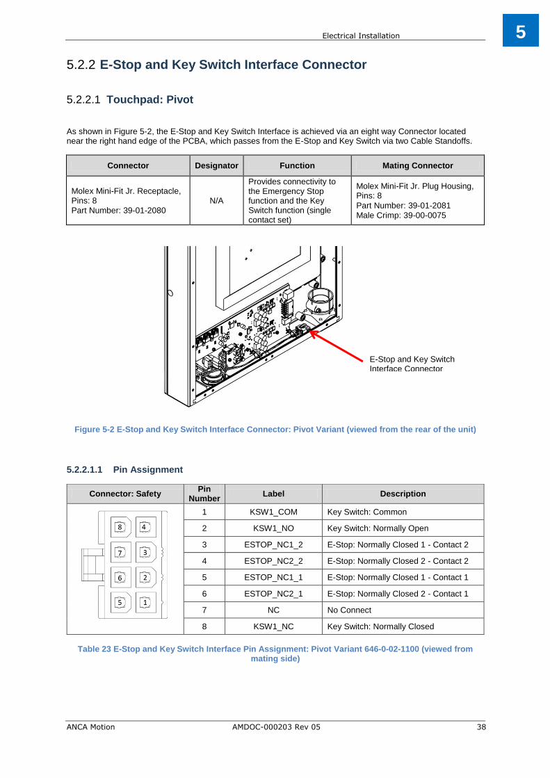
E-Stop and Key Switch Interface Connector 5.2.2
Touchpad: Pivot 5.2.2.1
As shown in Figure 5-2, the E-Stop and Key Switch Interface is achieved via an eight way Connector located near the right hand edge of the PCBA, which passes from the E-Stop and Key Switch via two Cable Standoffs.
Connector Designator Function Mating Connector
Molex Mini-Fit Jr. Receptacle, Pins: 8
Part Number: 39-01-2080
N/A
Provides connectivity to the Emergency Stop function and the Key Switch function (single contact set)
Molex Mini-Fit Jr. Plug Housing, Pins: 8
Part Number: 39-01-2081
Male Crimp: 39-00-0075
Figure 5-2 E-Stop and Key Switch Interface Connector: Pivot Variant (viewed from the rear of the unit)
5.2.2.1.1 Pin Assignment
Table 23 E-Stop and Key Switch Interface Pin Assignment: Pivot Variant 646-0-02-1100 (viewed from
mating side)
Connector: Safety Pin
Number Label Description
1 KSW1_COM Key Switch: Common
2 KSW1_NO Key Switch: Normally Open
3 ESTOP_NC1_2 E-Stop: Normally Closed 1 - Contact 2
4 ESTOP_NC2_2 E-Stop: Normally Closed 2 - Contact 2
5 ESTOP_NC1_1 E-Stop: Normally Closed 1 - Contact 1
6 ESTOP_NC2_1 E-Stop: Normally Closed 2 - Contact 1
7 NC No Connect
8 KSW1_NC Key Switch: Normally Closed
E-Stop and Key Switch Interface Connector

Electrical Installation
ANCA Motion AMDOC-000203 Rev 05 39
5
Touchpad: Mounting Arm 5.2.2.2 As shown in Figure 5-3, the E-Stop and Key Switch Interface is achieved via a ten way Connector located near the right hand edge of the PCBA, which passes from the E-Stop and Key Switch via two Cable Standoffs.
Connector Designator Function Mating Connector
Molex Mini-Fit Jr. Receptacle, Pins: 10
Part Number: 39-01-2100
N/A
Provides connectivity to the Emergency Stop function and the Key Switch function (two contact sets)
Molex Mini-Fit Jr. Plug Housing, Pins: 10
Part Number: 39-01-2101
Male Crimp: 39-00-0075
Figure 5-3 E-Stop and Key Switch Interface Connector: Mounting Arm Variant (viewed from the rear of the
unit)
5.2.2.2.1 Pin Assignment
Table 24 Switch Interface Pin Assignment: Mounting Arm Variant (viewed from mating side)
Connector: Safety Pin
Number Label Description
1 KSW1_COM Key Switch: Contact Set 1: Common
2 KSW1_NO Key Switch: Contact Set 1: Normally Open
3 ESTOP_NC1_2 E-Stop: Normally Closed 1 - Contact 2
4 ESTOP_NC2_2 E-Stop: Normally Closed 2 - Contact 2
5 KSW2_COM Key Switch: Contact Set 2: Common
6 ESTOP_NC1_1 E-Stop: Normally Closed 1 - Contact 1
7 ESTOP_NC2_1 E-Stop: Normally Closed 2 - Contact 1
8 KSW2_NC Key Switch: Contact Set 2: Normally Closed
9 KSW1_NC Key Switch: Contact Set 1: Normally Closed
10 KSW2_NO Key Switch: Contact Set 2: Normally Open
E-Stop and Key Switch Interface Connector

Electrical Installation
ANCA Motion AMDOC-000203 Rev 05 40
5
Touchpad: Pivot (646-2-02-1100) 5.2.2.3 As shown in Figure 5-4, the E-Stop Interface is achieved via a ten way Connector located near the right hand edge of the PCBA, which passes from the E-Stop via two Cable Standoffs.
Connector Designator Function Mating Connector
Molex Mini-Fit Jr. Receptacle, Pins: 10
Part Number: 39-01-2100 N/A
Provides connectivity to the Emergency Stop function
Molex Mini-Fit Jr. Plug Housing, Pins: 10
Part Number: 39-01-2101
Male Crimp: 39-00-0075
Figure 5-4 E-Stop Interface Connector: Pivot type 646-2-02-1100 (viewed from the rear of the unit)
5.2.2.3.1 Pin Assignment
Table 25 Switch Interface Pin Assignment: Pivot Variant 646-2-02-1100 (viewed from mating side)
Connector: Safety Pin
Number Label Description
1 NC No Connect
2 NC No Connect
3 ESTOP_NC1_2 E-Stop: Normally Closed 1 - Contact 2
4 ESTOP_NC2_2 E-Stop: Normally Closed 2 - Contact 2
5 NC No Connect
6 ESTOP_NC1_1 E-Stop: Normally Closed 1 - Contact 1
7 ESTOP_NC2_1 E-Stop: Normally Closed 2 - Contact 1
8 NC No Connect
9 NC No Connect
10 NC No Connect
E-Stop Interface Connector

Electrical Installation
ANCA Motion AMDOC-000203 Rev 05 41
5
Digital Video Interface Connector 5.2.3
As shown in Figure 5-5, the Touchpad Digital Video Interface is achieved via a HDMI Adaptor located on the right hand side of the rear of the Unit, which connects to the DVI-D connector on the rear of the Touch Screen.
Connector/Adaptor Designator Function Mating Connector
HDMI - Female N/A Display Digital Video Interface
HDMI - Male
Figure 5-5 Digital Video Interface Connector on the Touchpad (viewed from the rear of the unit)
HDMI – Female is NC

Electrical Installation
ANCA Motion AMDOC-000203 Rev 05 42
5
Customer Machine Chassis Earth Connection 5.2.4
As shown in Figure 5-6, the Chassis Earth connection between the Touchpad and the Customer Machine is achieved via an M5 Earth Stud (with M5 Nyloc Nut) located on the right hand internal side of the rear of the Unit. This also serves as the connection point for a short (user supplied) Chassis Earth connection to the M5 Earth Stud (with M5 Nyloc Nut) located at the rear bottom edge of the Touchpad Rear Panel.
Connector Designator Function Mating Connector
M5 Stud with M5 Nyloc Nut N/A Provides connectivity to the Customer Machine Safety Connection
Crimp Ring Terminal: M5 Combine with M5 Flat Washer
Figure 5-6 Customer Machine Chassis Earth Stud (viewed from the rear of the unit)
Customer Machine Chassis Earth Stud
Electrical Installation
ANCA Motion AMDOC-000203 Rev 05 43
5
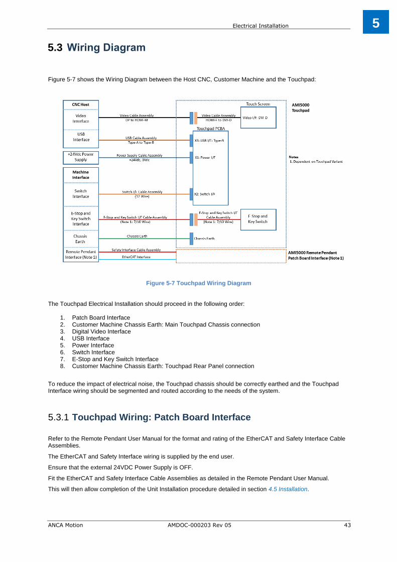
Wiring Diagram 5.3
Figure 5-7 shows the Wiring Diagram between the Host CNC, Customer Machine and the Touchpad:
Figure 5-7 Touchpad Wiring Diagram
The Touchpad Electrical Installation should proceed in the following order:
1. Patch Board Interface 2. Customer Machine Chassis Earth: Main Touchpad Chassis connection 3. Digital Video Interface 4. USB Interface 5. Power Interface 6. Switch Interface 7. E-Stop and Key Switch Interface 8. Customer Machine Chassis Earth: Touchpad Rear Panel connection
To reduce the impact of electrical noise, the Touchpad chassis should be correctly earthed and the Touchpad Interface wiring should be segmented and routed according to the needs of the system.
Touchpad Wiring: Patch Board Interface 5.3.1
Refer to the Remote Pendant User Manual for the format and rating of the EtherCAT and Safety Interface Cable Assemblies.
The EtherCAT and Safety Interface wiring is supplied by the end user.
Ensure that the external 24VDC Power Supply is OFF.
Fit the EtherCAT and Safety Interface Cable Assemblies as detailed in the Remote Pendant User Manual.
This will then allow completion of the Unit Installation procedure detailed in section 4.5 Installation.

Electrical Installation
ANCA Motion AMDOC-000203 Rev 05 44
5
Touchpad Wiring: Customer Machine Chassis Earth: Chassis 5.3.2 The Machine Chassis Earth Cable should be a single cable with an M5 Crimp Ring Terminal.
The Machine Chassis Earth Cable is supplied by the end user along with the associated M5 Flat Washer.
A short (150 mm) Rear Panel Chassis Earth Cable is also required with an M5 Crimp Ring Terminal at each end.
The Rear Panel Chassis Earth Cable is supplied by the end user.
Ensure that the external +24VDC Power Supply is OFF.
The Machine Chassis Earth Cable and the Rear Panel Chassis Earth Cable should connect to the M5 Earth Stud located on the right hand internal side of the rear of the Unit, using the integral M5 Nut and user supplied M5 Flat Washer.
The other end of the Rear Panel Chassis Earth Cable will be connected to the Touchpad Rear Panel later in the installation process as described in section 5.3.8 Touchpad Wiring: E-Stop and Key Switch Interface.
Ensure that the Touchpad chassis is correctly earthed to minimise the impact of any noise in the overall system.
Touchpad Wiring: Digital Video Interface 5.3.3
The Digital Video Interface Cable should be a single cable with HDMI-Male Termination.
The Digital Video Interface Cable is supplied by the end user.
Ensure that the external +24VDC Power Supply is OFF.
The Digital Video Interface Cable should connect to the HDMI-Female Adaptor on the top right hand side of the rear of the Unit (with appropriate routing and strain relief).
Touchpad Wiring: USB Interface 5.3.4
The USB Interface Cable should be a single cable with a Type-B Termination.
The USB Interface Cable is supplied by the end user.
Ensure that the external +24VDC Power Supply is OFF.
The USB Interface Cable should connect to the X3 connector on the Touchpad PCBA (with appropriate routing and strain relief).
Touchpad Wiring: Power Supply 5.3.5
The external +24VDC Power Supply for the Touchpad should be able to supply a minimum of 3A at +24Vdc.
The Power Supply feed should be a single cable with +24Vdc and 0Vdc connections (or a combination of separate cables).
The Power Supply wiring is supplied by the end user (note that a variety of Demonstration Looms are also available – refer to section 14.8 Demonstration Wiring Loom).
Ensure that the external +24VDC Power Supply is OFF.
The Power Supply Cable should connect to the X1 connector on the Touchpad PCBA (with appropriate routing and strain relief).

Electrical Installation
ANCA Motion AMDOC-000203 Rev 05 45
5
Touchpad Wiring: Switch Interface 5.3.6
The Switch Interface Cable should be rated appropriately for each connection (nominal 24Vdc 200mA).
The Switch Interface Cable should be a single twelve way cable (or a combination of separate cables).
The Switch Interface wiring is supplied by the end user (note that a variety of Demonstration Looms are also available – refer to section 14.8 Demonstration Wiring Loom).
Ensure that the external +24VDC Power Supply is OFF.
The Switch Interface Cable should connect to the X2 connector on the Touchpad PCBA (with appropriate routing and strain relief).
Touchpad Wiring: E-Stop and Key Switch Interface 5.3.7
The E-Stop and Key Switch Interface Cable should be rated appropriately for each connection (nominal 24Vdc 200mA).
The format of the E-Stop and Key Switch Interface Cable is dependent on the Touchpad variant:
Pivot: Single eight way cable
Mounting Arm: Single ten way cable
Alternatively, a combination of separate cables could be used.
The E-Stop and Key Switch Interface wiring is supplied by the end user (note that a variety of Demonstration Looms are also available – refer to section 14.8 Demonstration Wiring Loom).
Ensure that the external +24VDC Power Supply is OFF.
The E-Stop and Key Switch Interface Cable should connect to the eight/ten pin Connector located near the Cable Standoff on the right hand bottom edge of the PCBA (with appropriate routing and strain relief).
Touchpad Wiring: Customer Machine Chassis Earth: Rear 5.3.8
Panel
Ensure that the external +24VDC Power Supply is OFF.
As described in section 5.3.2 Touchpad Wiring: Patch Board Interface, one end of the Rear Panel Chassis Earth Cable has already been connected to the M5 Earth Stud located on the right hand internal side of the rear of the Unit.
The other end of the Rear Panel Chassis Earth Cable should be connected to the M5 Earth Stud located on the internal side of the Touchpad Rear Panel using the integral M5 Nut and user supplied M5 Flat Washer.

Unit Removal from Customer Machine
ANCA Motion AMDOC-000203 Rev 05 46
6
Unit Removal from Customer Machine 6
Introduction 6.1
This chapter describes the removal of the Touchpad from a typical Customer Machine:
Site requirements
Removal procedure
Site Requirements 6.2
The following is a set of requirements on the removal site:
The safety precautions outlined in 1 Safety must be understood and adhered to.
Ensure that the Power Supply to the Machine is in an OFF condition.
Removal Procedure: Pivot Variant 6.3
Tools Required:
Description Quantity Note
Socket Wrench 1 Required for disassembly
2.5 mm Hex Driver 1 Remove the Rear Panel from the Touchpad
3.0 mm Hex Driver 1 Remove the Lower Pivot mechanism from the Customer Machine
8 mm Socket 1 Loosen the M5 Earth Stud Nut
Loosen the Hose Clamp on the Pivot Bush
Table 26 Touchpad Removal: Tools Required
Removal Method:
Step Description Images
1 Ensure that the Power Supply to the Machine is in an OFF condition.
2 Ensure the Touchpad Key is placed in the Key Switch.

Unit Removal from Customer Machine
ANCA Motion AMDOC-000203 Rev 05 47
6
Step Description Images
3 Separate the Touchpad Rear Panel from the Main Chassis by removing and storing the twelve locating screws. Carefully lower the Rear Panel onto a nearby horizontal support.
4 Disconnect the Rear Panel Earth Cable from the Earth Stud located on the inside bottom of the Rear Panel. Safely store the Rear Panel.
5A Carefully disconnect the Customer Machine Interface Cables in the following order:
Digital Video: HDMI Connector/Assembly
5B USB Interface: PCBA X3

Unit Removal from Customer Machine
ANCA Motion AMDOC-000203 Rev 05 48
6
Step Description Images
5C Switch Interface (PCBA X2) and E-Stop and Key Switch Interface
5D Power Supply Interface: PCBA X1
6 Disconnect the Machine Chassis Earth Cable and the Rear Panel Chassis Earth Cable from the Earth Stud located on the bottom of the Touchpad Main Chassis (as shown).
7 Release the nut on the Hose Clamp (as shown).

Unit Removal from Customer Machine
ANCA Motion AMDOC-000203 Rev 05 49
6
Step Description Images
8 Rotate the Touchpad Chassis to a position perpendicular to the Machine. Whilst holding the Touchpad Chassis in position, remove the Machine Upper Pivot Plate from the Machine by carefully removing the mounting bolts. Store the Upper Pivot Plate carefully.
9 Carefully lift the Touchpad Chassis upwards to clear the Lower Pivot Clamp Plate Assembly. Hold the Touchpad Chassis in position close to the Lower Pivot Clamp Plate Assembly. Carefully extract the Machine Interface Cables from the Touchpad in the following order: 1) Machine Chassis Earth Interface 2) USB Interface 3) Power Interface 4) E-Stop and Key Switch Interface 5) Switch Interface 6) Digital Video Interface
10 If required, the Lower Pivot Clamp Plate Assembly can be removed from the Customer Machine by loosening the four M5 SHCS screws (ICN-3001-3251).
Unit Removal from Customer Machine
ANCA Motion AMDOC-000203 Rev 05 50
6
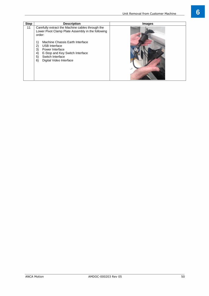
Step Description Images
11 Carefully extract the Machine cables through the Lower Pivot Clamp Plate Assembly in the following order: 1) Machine Chassis Earth Interface 2) USB Interface 3) Power Interface 4) E-Stop and Key Switch Interface 5) Switch Interface 6) Digital Video Interface

Unit Removal from Customer Machine
ANCA Motion AMDOC-000203 Rev 05 51
6
Removal Procedure: Mounting Arm Variant 6.4 Tools Required:
Description Quantity Note
Socket Wrench 1 Required for disassembly
2.5 mm Hex Driver 1 Remove the Rear Panel from the Touchpad
3.0 mm Hex Driver 1 Remove the Keyboard Tray from the chassis
Remove the Cradle Bracket from the chassis
4.0 mm Hex Driver 1 Release the Mounting Arm from the Rear Panel
Remove the Cradle from the Cradle Bracket
8 mm Socket 1 Loosen the M5 Earth Stud Nut
Table 27 Touchpad Removal: Tools Required
Removal Method:
Step Description Images
1 Ensure that the Power Supply to the Machine is in an OFF condition.
2
Ensure the Touchpad Key is placed in the Key Switch.
3
Remove the Remote Pendant harness plug from the Patch Board connector located on the Rear Panel as shown and refit the red plug cover from the cable end (previously stored).

Unit Removal from Customer Machine
ANCA Motion AMDOC-000203 Rev 05 52
6
Step Description Images
4
Remove the Remote Pendant from the Cradle fixture.
5
Detach the Keyboard Tray by removing the six M5 screws located on the bottom face of the Touchpad chassis. Store the Keyboard Tray and then refit and hand tighten the six M5 screws. Detach the Cradle Bracket by removing the two M5 screws located on either the left side or right side face of the Touchpad chassis, depending on the customer fitment option. Store the Cradle Bracket and then refit and hand tighten the two M5 screws.
6
Rotate the Mounting Arm joint so that the Rear Panel of the Touchpad is in a vertical orientation. Separate the Touchpad Rear Panel from the Main Chassis by removing and storing the twelve M4 locating screws.
Keyboard Tray
Cradle Bracket

Unit Removal from Customer Machine
ANCA Motion AMDOC-000203 Rev 05 53
6
Step Description Images
7
Gently open the Touchpad Chassis from the lower side, pivoting against the top of the Rear Panel.
Carefully remove the Rod Stay from the Rear Panel paying particular attention to the proximity of the Patch Board.
Note: Ensure the Rod Stay does not contact the
Patch Board during the removal process.
Extend the Rod Stay and fix the M4 spring loaded fastener on the end of the Rod Stay to the blind nut located midway on the bottom lip of the Touchpad Chassis (as shown).
Ensure this M4 Fastener is only hand tightened
as the Rod Stay will be removed and stowed in its original position during a subsequent step in the removal process.
The Touchpad will be held open due to the orientation of the Rod Stay.
Unit Removal from Customer Machine
ANCA Motion AMDOC-000203 Rev 05 54
6
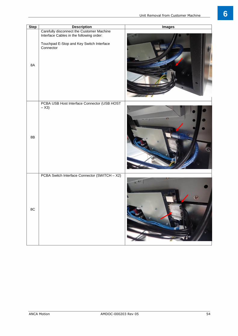
Step Description Images
8A
Carefully disconnect the Customer Machine Interface Cables in the following order: Touchpad E-Stop and Key Switch Interface Connector
8B
PCBA USB Host Interface Connector (USB HOST – X3)
8C
PCBA Switch Interface Connector (SWITCH – X2)

Unit Removal from Customer Machine
ANCA Motion AMDOC-000203 Rev 05 55
6
Step Description Images
8D
PCBA Power Interface Connector (D24V IN – X1)
8E
Video I/F: HDMI (F) The associated Cable Tie at position A will also need to be removed.
8F
Disconnect the Machine Chassis Earth Cable and the Rear Panel Chassis Earth Cable from the Earth Stud located on the bottom of the Touchpad Main Chassis.

Unit Removal from Customer Machine
ANCA Motion AMDOC-000203 Rev 05 56
6
Step Description Images
9
Remove the Rod Stay from the Main Chassis by loosening the M4 spring loaded fastener. Fit the Rod Stay securely to the Rear Panel using the two plastic clips as shown.
10
Confirm that the Mounting Arm joint is rotated so that the Rear Panel of the Touchpad is in a vertical orientation. Lift the Touchpad chassis up and away from the Rear Panel and store safely. Note: Care must be taken during the removal of the Touchpad chassis from the Rear Panel to prevent damage to the surrounding gasket.
11
Disconnect the Rear Panel Chassis Earth Cable from the Earth Stud located on the Touchpad Rear Panel.
Unit Removal from Customer Machine
ANCA Motion AMDOC-000203 Rev 05 57
6
Step Description Images
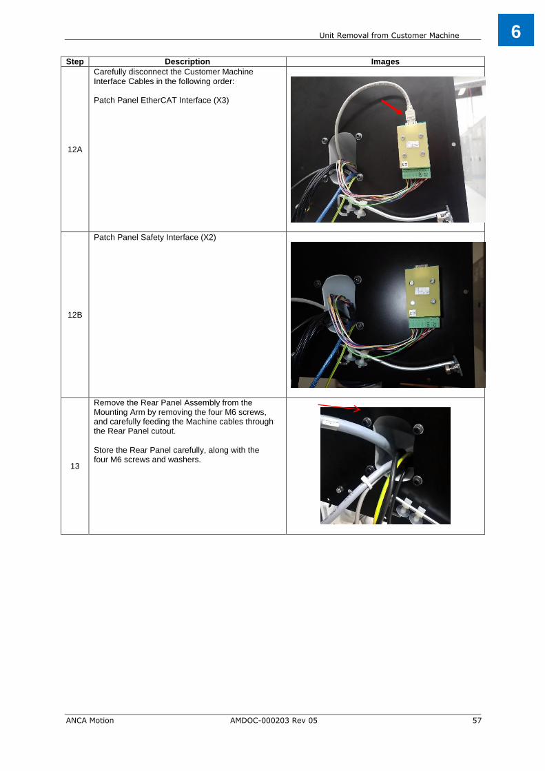
12A
Carefully disconnect the Customer Machine Interface Cables in the following order: Patch Panel EtherCAT Interface (X3)
12B
Patch Panel Safety Interface (X2)
13
Remove the Rear Panel Assembly from the Mounting Arm by removing the four M6 screws, and carefully feeding the Machine cables through the Rear Panel cutout. Store the Rear Panel carefully, along with the four M6 screws and washers.

E-Stop and Key Switch
ANCA Motion AMDOC-000203 Rev 05 58
7
E-Stop and Key Switch 7
Connection of the E-Stop and Key Switch 7.1
The Touchpad contains two switches which are located at the bottom right hand corner of the Touchpad:
E-Stop (Emergency Stop) Switch
Key Switch
These two devices are wired from the Touchpad to the Customer Machine via a user supplied cable (refer to section 5.3.7 Touchpad Wiring: Switch Interface).
The user can connect to the switches via a separate eight/ten pin Connector located near the Cable Standoff on the right hand bottom edge of the Touchpad PCBA.
The interface used for connection of the E-Stop and the Key Switch is normally supplied with the Customer Machine.
E-Stop Switch Configuration 7.2
The E-Stop Switch consists of three contact pairs (NC1, NC2 and NC3) with two of these contact pairs (NC1 and NC2) being available on the E-Stop and Key Switch Interface.
Each contact pair consists of two connections:
Contact Pair NC1: ESTOP_NC1_1 and ESTOP_NC1_2
Contact Pair NC2: ESTOP_NC2_1 and ESTOP_NC2_2
Both contact pairs are normally closed when the E-Stop is released (normal operation):
Contact Pair NC1: Short circuit between ESTOP_NC1_1 and ESTOP_NC1_2
Contact Pair NC2: Short circuit between ESTOP_NC2_1 and ESTOP_NC2_2
Both contact pairs are open when the E-Stop is engaged (stop operation):
Contact Pair NC1: Open circuit between ESTOP_NC1_1 and ESTOP_NC1_2
Contact Pair NC2: Open circuit between ESTOP_NC2_1 and ESTOP_NC2_2

E-Stop and Key Switch
ANCA Motion AMDOC-000203 Rev 05 59
7
Key Switch Configuration 7.3
The Key Switch consists of two contact sets (1, 2).
The specific contact sets available on the E-Stop and Key Switch Interface are dependent on the Touchpad variant:
Pivot: Contact Set 1
Mounting Arm: Contact Set 1, Contact Set 2
Each contact set consists of three terminals:
Contact Set 1: Common, Normally Open (NO), Normally Closed (NC)
Contact Set 2: Common, Normally Open (NO), Normally Closed (NC)
The Common and NC terminals of both contact sets are normally connected when the Key Switch is set to the OFF position:
Contact Set 1: Short circuit between Common and NC
Contact Set 2: Short circuit between Common and NC
The Common and NO terminals of both contact sets are normally connected when the Key Switch is set to the ON position:
Contact Set 1: Short circuit between Common and NO
Contact Set 2: Short circuit between Common and NO

Installation Checklist for the Touchpad
ANCA Motion AMDOC-000203 Rev 05 60
8
Installation Checklist for the Touchpad 8
Introduction 8.1
This chapter contains a checklist for the end user to implement and refer to before powering up the Touchpad.
Installation Checklist 8.2
The installation location satisfies the requirements in section 4 Mechanical Installation
The supply voltage is within the operating limits of the Touchpad: +20.4Vdc to +28.8Vdc
The wiring is connected to the appropriate terminals and the conductors are secured
The appropriate power supply fuses have been installed
All wiring conforms to applicable regulations and standards
No physical damage is present to any component within the system
All equipment connected to the Touchpad is ready for start-up
A risk assessment meeting the required safety standard has been completed on the entire Machine
Table 28 Installation Checklist

Commissioning and Testing
ANCA Motion AMDOC-000203 Rev 05 61
9
Commissioning and Testing 9
Testing/Power-on Checks 9.1 The following procedure must be adhered to during start up to ensure safe operation and functionality:
1. Ensure all wiring is secure and there are no short circuits at the user installed connectors.
2. Plug in all connectors as described in section 5 Electrical Installation.
3. All equipment connected to the Touchpad is ready for start-up.
4. The Touchpad E-Stop Switch is engaged.
5. The Touchpad Key Switch is set to OFF.
6. Ambient temperature is within 0 to +40C.
7. A Machine risk assessment has been performed and the Machine has been assessed as safe to use.
8. Ensure the external +24V Power Supply input is within the range +20.4Vdc to +28.8Vdc.
Commissioning Checks 9.2 The following procedure should be followed to commission the Touchpad:
1. Check the default Touchpad status:
a. E-Stop engaged
b. Key Switch set to OFF
2. Check the default Machine status:
a. Ensure the Operating Door is Closed
3. Turn on the Power Source for the external +24Vdc Power Supply for the System (and the Touchpad)
4. Turn the System ON by momentarily depressing and releasing the ‘CTRL ON’ Switch:
a. Check that the ‘CTRL ON’ Switch LED is now ON
b. Check that the Host CNC enters the ON state and commences its Boot Up sequence
5. Check the operation of the Video Interface:
a. Check that the Touchpad Display shows the following image sequence:
i. Boot Up Screen
ii. Operating System Home Screen
iii. CNC Application Screen
b. Wait for completion of the Machine initialisation sequence
6. Check the operation of the Audio Interface:
a. Check that the default Host CNC Audio Output source is set to USB AUDIO CODEC
b. Set the Host CNC Audio Output Level to 50%
c. Confirm that the default Operating System Event Tones are audible

Commissioning and Testing
ANCA Motion AMDOC-000203 Rev 05 62
9
7. Check the operation of the USB Interface:
a. Confirm the correct operation of the three External USB Ports:
i. Insert a USB Disk Drive into each External USB Port and confirm Host CNC recognition
b. Check that the Display Multi-point Touchpad Interface is operational
8. Release the E-Stop and check the operation of the following Switches and their LED Indicators through appropriate System functions or sequences:
a. DOOR OPEN
b. CYCLE START
c. SPINDLE START
d. SPINDLE STOP
9. Check the operation of the ‘CTRL ON’ Latch function (if configured):
a. Momentarily depress and release the ‘CTRL ON’ Switch
b. Confirm the ‘CTRL ON’ Switch LED remains ON
c. Confirm that the Host CNC remains in the ON state
10. Check the operation of the E-Stop:
a. Initiate a suitable System function or sequence which responds to the operation of the E-Stop
b. Engage the E-Stop:
i. Confirm that the System responds correctly to the operation of the E-Stop
ii. For the Pivot Variant, confirm that the position of the Touchpad is effectively maintained by the pivot mechanism
c. Release the E-Stop
d. Re-initiate a suitable System function or sequence which responds to the operation of the E-Stop and confirm it is successfully executed
11. Check the operation of the Key Switch:
a. Ensure the Machine is in an Idle Mode
b. Set the Key Switch to ON
c. Confirm that the Display/Machine indicates recognition of Key Switch ON state
d. Set the Key Switch to OFF
e. Confirm that the Display/Machine indicates recognition of Key Switch OFF state
12. For the Pivot Variant:
a. Confirm the Rear Bump Stop prevents the Touchpad touching the Machine Chassis when the Touchpad is in the fully recessed position
b. Confirm that the Touchpad rotates freely with a degree of resistance about a vertical axis defined by the Upper and Lower Pivot components
13. For the Mounting Arm Variant:
a. Confirm correct operation of the Remote Pendant (if fitted)
b. Confirm that the Touchpad and the attached Mounting Arm interface move freely

Operation
ANCA Motion AMDOC-000203 Rev 05 63
10
Operation 10
Display Interface 10.1
The Display Interface consists of a 19 inch Display and a multi-point Touchpad Interface.
The Display has a nominal resolution of 1024 x 1280 (H x V) in Portrait Mode (refer to the latest PMK User Manual for the Display configuration).
The brightness of the Display is fixed at 100% and is not adjustable by the customer.
The Display uses a Digital Video Interface connection.
The multi-point Touchpad Interface can be used in parallel with another Pointing device such as an External Mouse.
Surface scratches, dirt or grease can lead to compromised operation of the multi-point Touchpad Interface. The user should ensure that the interface is treated appropriately with only the use of a hand (with clean fingers) or a stylus.
External USB Interface 10.2
Three External USB Ports with a Type-A Connector are provided on the Touchpad.
Each Port is Bus Powered with a maximum current limit of 500 mA.
Typical devices that can be used on the External USB Ports include an External Mouse, External Keyboard, External Hard Disk Drive, and a USB Disk Drive.
Each External USB Port is fitted with a Protection Cap which should be closed over the Port when it is not in use to avoid the ingress of foreign substances.
When an overcurrent condition occurs on an External USB Port, the Operating System will display a notification flag and icon in the Notification Area of the Taskbar. The error can be cleared by double clicking the USB icon in the notification tray and following the prompts.
Audio Interface 10.3
The volume and mute status of the Audio Interface signal can be adjusted using the Windows Sound Level control, in addition to the Windows Sound Mixer and individual Application Volume controls.
Switch Interface 10.4
A total of five momentary action Tactile Switches (SW1, SW2, SW3, SW4, SW5) are used to control specific System functions.
Four momentary action Tactile Switches are provided with a non latching function:
DOOR OPEN (SW2)
CYCLE START (SW3)
SPINDLE STOP (SW4)
SPINDLE START (SW5)
One momentary action Tactile Switch is provided with a latching function:
CTRL ON (SW1)
The Front Panel layout of the five momentary action Tactile Switches is as follows:

Operation
ANCA Motion AMDOC-000203 Rev 05 64
10
Figure 10-1 Front Panel Switch Layout
Each Tactile Switch includes an associated LED Indicator which is illuminated when +24Vdc is applied to the associated LED Drive Signal:
SW1: LED1
SW2: LED2
SW3: LED3
SW4: LED4
SW5: LED5
When the DOOR OPEN (SW2), CYCLE START (SW3), SPINDLE STOP (SW4) or SPINDLE START (SW5) Tactile Switches are depressed, +24Vdc is provided on the associated Output Contact.
When the DOOR OPEN (SW2), CYCLE START (SW3), SPINDLE STOP (SW4) or SPINDLE START (SW5) Tactile Switches are not depressed, an Open Circuit is provided on the associated Output Contact.
Figure 10-2 Touchpad Switch Interface Wiring Diagram
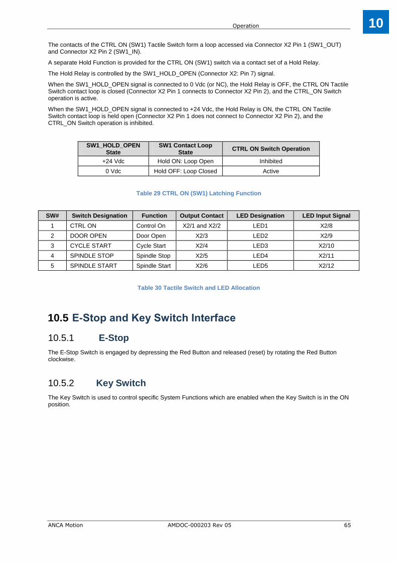
Operation
ANCA Motion AMDOC-000203 Rev 05 65
10
The contacts of the CTRL ON (SW1) Tactile Switch form a loop accessed via Connector X2 Pin 1 (SW1_OUT) and Connector X2 Pin 2 (SW1_IN).
A separate Hold Function is provided for the CTRL ON (SW1) switch via a contact set of a Hold Relay.
The Hold Relay is controlled by the SW1_HOLD_OPEN (Connector X2: Pin 7) signal.
When the SW1_HOLD_OPEN signal is connected to 0 Vdc (or NC), the Hold Relay is OFF, the CTRL ON Tactile Switch contact loop is closed (Connector X2 Pin 1 connects to Connector X2 Pin 2), and the CTRL_ON Switch operation is active.
When the SW1_HOLD_OPEN signal is connected to +24 Vdc, the Hold Relay is ON, the CTRL ON Tactile Switch contact loop is held open (Connector X2 Pin 1 does not connect to Connector X2 Pin 2), and the CTRL_ON Switch operation is inhibited.
SW1_HOLD_OPEN State
SW1 Contact Loop State
CTRL ON Switch Operation
+24 Vdc Hold ON: Loop Open Inhibited
0 Vdc Hold OFF: Loop Closed Active
Table 29 CTRL ON (SW1) Latching Function
SW# Switch Designation Function Output Contact LED Designation LED Input Signal
1 CTRL ON Control On X2/1 and X2/2 LED1 X2/8
2 DOOR OPEN Door Open X2/3 LED2 X2/9
3 CYCLE START Cycle Start X2/4 LED3 X2/10
4 SPINDLE STOP Spindle Stop X2/5 LED4 X2/11
5 SPINDLE START Spindle Start X2/6 LED5 X2/12
Table 30 Tactile Switch and LED Allocation
E-Stop and Key Switch Interface 10.5
E-Stop 10.5.1
The E-Stop Switch is engaged by depressing the Red Button and released (reset) by rotating the Red Button clockwise.
Key Switch 10.5.2
The Key Switch is used to control specific System Functions which are enabled when the Key Switch is in the ON position.
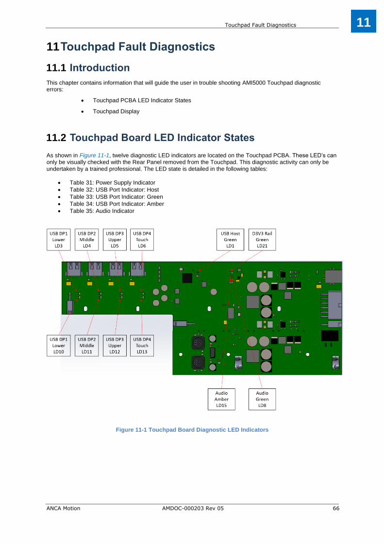
Touchpad Fault Diagnostics
ANCA Motion AMDOC-000203 Rev 05 66
11
Touchpad Fault Diagnostics 11
Introduction 11.1
This chapter contains information that will guide the user in trouble shooting AMI5000 Touchpad diagnostic errors:
Touchpad PCBA LED Indicator States
Touchpad Display
Touchpad Board LED Indicator States 11.2 As shown in Figure 11-1, twelve diagnostic LED indicators are located on the Touchpad PCBA. These LED’s can only be visually checked with the Rear Panel removed from the Touchpad. This diagnostic activity can only be undertaken by a trained professional. The LED state is detailed in the following tables:
Table 31: Power Supply Indicator
Table 32: USB Port Indicator: Host
Table 33: USB Port Indicator: Green
Table 34: USB Port Indicator: Amber
Table 35: Audio Indicator
Figure 11-1 Touchpad Board Diagnostic LED Indicators

Touchpad Fault Diagnostics
ANCA Motion AMDOC-000203 Rev 05 67
11
Power Supply Indicator 11.2.1 The D3V3 Rail is normally active when the AMI5000 Touchpad is in a powered state, as indicated by LED LD21. The +24 Vdc Power Supply and its connection to the Touchpad PCBA via Connector X1 should be checked if LED LD21 is OFF.
LED
(Green) LED State Description Default Note
LD21 ON D3V3 Supply Active Default
OFF D3V3 Supply Inactive N/A Check +24 Vdc Power Supply Connection
Table 31 Power Supply LED Indicator States
USB Port Indicators 11.2.2 The Upstream USB Port connection to the Host CNC is normally set to a High Speed Mode (<= 480 Mbps) when the AMI5000 Touchpad is in a powered state, as indicated by LED LD1. The Host CNC configuration and its connection to the Touchpad PCBA via Connector X3 should be checked if LED LD1 is OFF, indicating a Full Speed Mode connection (<= 12 Mbps) or no connection.
LED
(Green) Description Allocation
LED State
Default Note
LD1 Upstream Port: High
Speed
Host
ON Default Host Port: High Speed (<= 480 Mbps)
OFF N/A Host Port: Full Speed (<= 12 Mbps)
Table 32 Host USB Port Status LED Indicator States
There are a total of five Downstream USB Port connections with the following allocation:
External USB Ports: Total of three (Upper, Middle, Lower)
Internal Touchpad Interface: One
Internal Audio Interface: One (refer to section 11.2.3 Audio LED Indicators)
Each Downstream USB Port is provided with two LED State indicators:
Green Status LED
Amber Status LED
USB Devices connected to an External USB Port (Upper, Middle or Lower) are normally enumerated and in an Operational - No Error mode when the AMI5000 Touchpad is in a powered state, as indicated by the associated Green (ON) and Amber (OFF) LED states. The connection of the USB Device to the External USB Port should be checked if the Green LED is OFF or Amber LED is ON, indicating a configuration or connection issue. The interconnecting USB Cable from the Touchpad PCBA to the rear of the specific External USB Port should also be checked if required. The configuration of the USB Hub Controller on the Touchpad PCBA should also be checked via the Host CNC Device Manager. The USB Hub Controller can be reset via a Disable/Enable sequence through the Host CNC Device Manager. When an overcurrent condition occurs on an External USB Port, the Operating System should display a notification flag and icon in the Notification Area of the Taskbar. The error can be cleared by double clicking the USB icon in the notification tray and following the prompts.

Touchpad Fault Diagnostics
ANCA Motion AMDOC-000203 Rev 05 68
11
LED (Green)
Description Allocation LED State
Default Note
LD3 Downstream Port 1
(DP1): Status External USB Port:
Lower
ON N/A Enumerated: Operational
OFF N/A Not Enumerated
LD4 Downstream Port 2
(DP2): Status External USB Port:
Middle
ON N/A Enumerated: Operational
OFF N/A Not Enumerated
LD5 Downstream Port 3
(DP3): Status External USB Port:
Upper
ON N/A Enumerated: Operational
OFF N/A Not Enumerated
LD6 Downstream Port 4
(DP4): Status Touchpad I/F
ON Default Enumerated: Operational
OFF N/A Not Enumerated
Table 33 USB Port Status LED (Green) Indicator States
LED (Green)
Description Allocation LED State
Default Note
LD10 Downstream Port 1
(DP1): Status External USB Port:
Lower
ON N/A Enumerated: Error
OFF Default Enumerated: No Error
LD11 Downstream Port 2
(DP2): Status External USB Port:
Middle
ON N/A Enumerated: Error
OFF Default Enumerated: No Error
LD12 Downstream Port 3
(DP3): Status External USB Port:
Upper
ON N/A Enumerated: Error
OFF Default Enumerated: No Error
LD13 Downstream Port 4
(DP4): Status Touchpad I/F
ON N/A Enumerated: Error
OFF Default Enumerated: No Error
Table 34 USB Port Status LED (Amber) Indicator States
Audio LED Indicators 11.2.3 The Audio USB Interface from the Host CNC is normally enumerated and in an Operational - No Error mode when the AMI5000 Touchpad is in a powered state, as indicated by the Green LD8 (ON) and Amber LD15 (OFF) LED states. The configuration of the USB Hub Controller on the Touchpad PCBA should be checked via the Host CNC Device Manager if the Green LED is OFF or the Amber LED is ON, indicating a configuration or connection issue. The USB Hub Controller can be reset via a Disable/Enable sequence through the Host CNC Device Manager.
LED Description LED State
Default Note
LD8 USB Audio: Green LED:
Status
ON Default Enumerated: Operational
OFF N/A Not Enumerated
LD15 USB Audio: Amber LED:
Status
ON N/A Enumerated: Error
OFF Default Enumerated: No Error
Table 35 Audio Status LED Indicator States

Touchpad Fault Diagnostics
ANCA Motion AMDOC-000203 Rev 05 69
11
Touchpad Display 11.3
The AMI5000 Touchpad incorporates a 19 inch Display with an integrated multi-point Touchpad Interface.
Display 11.3.1
The Display is connected to the Host CNC via a Digital Video interface connection (Host Display Port to Touchpad DVI-D) and is normally in an ON state when the AMI5000 Touchpad is in a powered state, as indicated by an active Display image.
The Digital Video interface connection is achieved by an active Display Port to HDMI Adaptor Cable from the Host CNC to the Touchpad Chassis, and then a passive HDMI to DVI-D Adaptor to the DVI-D connector on the rear of the Display.
The +24 Vdc Power Supply and its connection to the Touchpad PCBA via Connector X1 should be checked if there is no active Display image. Other items that should be checked include the state of the Host CNC (powered), the interconnecting Display D12V Power Cable from the Touchpad Board to the rear of the Display, and the Digital Video connection to the Touchpad via the DVI-D to HDMI Adaptor in the rear of the Unit.
The brightness of the Display is fixed at 100% and is not adjustable by the customer.
Multi-point Touchpad Interface 11.3.2
The Display Multi-point Touchpad Interface is connected to the Host CNC via USB Downstream Port 4 (DP4) on the Touchpad PCBA. It is normally enumerated and in an Operational - No Error mode when the AMI5000 Touchpad is in a powered state, as indicated by the Green (ON) and Amber (OFF) LED states (refer to section 11.2.2 USB Port Indicators).
The USB connection of the Display to the Touchpad PCBA should be checked if the Green LED (LD6) is OFF or the Amber LED (LD13) is ON, indicating a configuration or connection issue. The configuration of the USB Hub Controller on the Touchpad PCBA should also be checked via the Host CNC Device Manager. The USB Hub Controller can be reset via a Disable/Enable sequence through the Host CNC Device Manager. The Touch Screen surface should be regularly cleaned to ensure the screen is free from any dirt or grease, thereby optimising the sensitivity of the multi-point touch interface. Using water only, clean the screen with a lint free damp cloth.
Multi-point Touchpad Interface: Calibration Procedure 11.3.3
The Multi-point Touchpad Interface should be calibrated (as required) using the following procedure:
Access the Calibrate Tool under the Control Panel > Tablet PC Settings selection
Switch to the Display Tab of the Tablet PC Settings dialogue
Select the Display as “ICN-3120-1041” and activate the Calibrate Task
Follow the on screen instructions to calibrate the Touchscreen, which will involve position confirmation of multiple points across the face of the display, and the saving of the calibration data

Standards Conformity
ANCA Motion AMDOC-000203 Rev 05 70
12
Standards Conformity 12
CE Compliance 12.1 A CE mark is attached to the Product Label in order to verify that the unit meets the relevant Environmental and Electromagnetic Compliance (EMC) directives of the European Union.

Standards Conformity
ANCA Motion AMDOC-000203 Rev 05 71
12
FCC Marking 12.2A FCC mark is attached to the Product Label in order to verify that the unit meets the relevant Electromagnetic Compliance (EMC) standards of the Federal Communications Commission.

Specifications
ANCA Motion AMDOC-000203 Rev 05 72
13
Specifications 13
Electrical 13.1
Attribute Qualification
Power Supply 13.1.1Supply Voltage +24Vdc -15/+20%
Supply Current Nominal: 2A, Maximum: 3A
Protection Input Transient and Reverse Polarity
Power Supply Interface Connector Manufacturer: Molex, Series: Mini Fit Jr, Type: Header, Pins: 2
Molex Part Number: 39-30-1021
Switch Interface 13.1.2Tactile Switch Activate Force 3N
Tactile Switch Travel Distance Total Travel Distance: 1.0 mm
Tactile Switch Contacts NO Momentary
Tactile Switch Contact Rating 24Vdc at 50mA
Tactile Switch: LED: Colour Red
Tactile Switch: LED: Drive Control Drive Signal: +24Vdc (High): LED ON (Drive Current: 5mA) Drive Signal: 0Vdc (Low): LED OFF
Tactile Switch: Protection
Provided by Resettable PTC
Nominal Current: 50mA
Trip Overload Current: 200mA
Switch: Control ON
Function: Control ON
Switch Function: Closed momentary - then remain open until power off
Latching Function provided by Relay SPDT NC Contact, Drive Signal: +24Vdc at 10mA
Colour: Green outline
Label: CTRL ON
Switch: Door Open
Function: Door Open
Switch Function: NO Momentary
Colour: White
Label: DOOR OPEN
Switch: Cycle Start
Function: Cycle Start
Switch Function: NO Momentary
Colour: Green
Label: CYCLE START
Switch: Spindle Stop
Function: SPINDLE STOP
Switch Function: NO Momentary
Colour: Red
Label: SPINDLE STOP
Switch: Spindle Start
Function: SPINDLE START
Switch Function: NO Momentary
Colour: White
Label: SPINDLE START
Switch Interface Connector Manufacturer: Molex, Series: Mini Fit Jr, Type: Header, Pins: 12
Molex Part Number: 39-30-1121

Specifications
ANCA Motion AMDOC-000203 Rev 05 73
13
1 This was measured with 180deg angle and split into two sets of 90deg for each direction in the axis of measurement. This
value is from the centre outwards, tangent to the screen face being 0deg. 2 Bright spot on a black background is caused by sub-pixels (in this case, a red sub-pixel) in the "on" state
3 Dark spot on a white background results from a green sub-pixel, which is in the "off" or dark state
4 Bright white dot or very noticeable black dot on the display
E-Stop and Key Switch Interface 13.1.3E-Stop: Contacts COM + NC (SPST) - 2 wires x 2 pairs (4 wire)
Key Switch: Contacts Contact Set 1: COM + NC + NO (SPDT)
Contact Set 2: COM + NC + NO (SPDT)
Key Switch: Active Contact Sets Pivot Variant: Contact Set 1
Mounting Arm Variant: Contact Set 1 and Set 2
Key Switch: Labels SETUP: ON: COM connects to NO
SETUP: OFF: COM connects to NC
E-Stop and Key Switch Interface Connector: Pivot Variant
Manufacturer: Molex, Series: Mini Fit Jr, Type: Receptacle, Pins: 8
Molex Part Number: 39-01-2080
E-Stop and Key Switch Interface Connector: Mounting Arm Variant
Manufacturer: Molex, Series: Mini Fit Jr, Type: Receptacle, Pins: 10
Molex Part Number: 39-01-2100
Audio Interface 13.1.4Audio: Source Digital Signal Source: USB CODEC
Audio: Volume Control Provided by Host Application
Audio: Output Signal Monophonic
Audio: Output Power Level Nominal: 2W, Maximum: 3W
Video Interface 13.1.5Display Type LCD TFT with Active Matrix
Screen Size 19 inch Diagonal
Active Area 377 x 302mm (Horizontal x Vertical)
Aspect Ratio 5:4
Contrast Ratio 1000:1
Vertical Viewing Angle1 80deg
Horizontal Viewing Angle1 85deg
Central Luminance 250cd/m2
Video Interface Type Digital
Video Resolution Minimum: 1280 x 1024 (W x H referenced to Landscape Mode)
Colour Depth 24 bit
Refresh Rate 60 to 75Hz
Video Interface Connector DVI-D: Single Link: Female
Bright sub-pixel defects2 1 maximum
Dark sub-pixel defects3 2 maximum
Total combined bright and dark sub-pixel defects 2 maximum
Full Pixel Defects pixel defects:4 0 allowed

Specifications
ANCA Motion AMDOC-000203 Rev 05 74
13
Mechanical 13.2
Touch Interface 13.1.6Touch Interface: Type Capacitive
Touch Interface: Area Entire Active Display area
Touch Interface: Surface Glass
Touch Interface: Multi-Touch Support for two touch points
USB Interface 13.1.7Number of External Ports External: Three Ports
USB Hub Type Powered
Power Source Internal Power Source
External Connector (Receptacle) Type A
Number of Host Ports One
Physical Standard USB 2.0 (Hi-Speed)
Line Rate 480Mbps
USB Interface Connector: Host (Receptacle) Type B
Attribute Qualification
Physical 13.2.1
Dimensions: Overall: Pivot Variant
Width: 390mm (Main Chassis width only)
Depth: 65mm (Rear Panel to the Front Panel)
Height: 540mm (Main Chassis height only)
Width: 395mm (USB cover to the Main Chassis)
Depth: 112mm (Rear Panel bump stop to the Key Switch)
Height: 547mm (Lower Pivot Plate to the top of the Main Chassis)
Dimensions: Overall: Mounting Arm Variant
Width: 390mm (Main Chassis width only)
Depth: 67mm (Rear Panel to the Front Panel)
Height: 540mm (Main Chassis height only)
Width: 395mm (USB cover to the Main Chassis)
Depth: 97mm (Rear Panel to the Key Switch)
Material Steel
Weight Pivot Variant: 11.5kg
Mounting Arm Variant: 13.5kg
Mounting: Method Pivot Variant: Integral Pivot with External Fixings (Top and Bottom)
Mounting Arm Variant: Rolec profiPLUS 50 Mounting Arm
Mounting: Orientation Vertical
Protection Rating: Electrical Circuits IP22 when fully assembled
IP53 when incorporated within the Main Chassis
Protection Rating: Overall IP53

Specifications
ANCA Motion AMDOC-000203 Rev 05 75
13
AMI5000 Touchpad Overall Dimensions 13.3
Figure 13-1 Touchpad Overall Dimensions
Environmental 13.2.2Ambient Temperature: Operating 0 to +40C
Relative Humidity: Operating 5 to 85% non-condensing
Ambient Temperature: Storage -25 to +55C
Relative Humidity: Storage 5 to 95%
Dust and Solid Particles Clean air, Pollution degree 2 (IEC 60664-1)
Vibration Class 3M1

Specifications
ANCA Motion AMDOC-000203 Rev 05 76
13
Fitment Dimensions for Typical Machine: Pivot 13.4
Variant
Figure 13-2 Fitment Dimensions for Typical Machine: Pivot Variant

Specifications
ANCA Motion AMDOC-000203 Rev 05 77
13
Upper Pivot Bracket Dimensions: Pivot Variant 13.5
Figure 13-3 Upper Pivot Bracket Dimensions: Pivot Variant
Lower Pivot Mounting Details: Pivot Variant 13.6
Figure 13-4 Lower Pivot Mounting Details: Pivot Variant
The Lower Mounting surface has a central access hole diameter of 40 mm for cable ingress and four tapped holes (M5x0.8) for the Mounting Bolts (ICN-3001-3251). The Lower Pivot Clamp Plate Assy (646-0-00-8639) has four clearance holes each of diameter 6 mm. Four M5 Mounting Bolts (Socket Head Cap Screw Low Head M5x16mm, ICN-3001-3251) are used to secure the Lower Pivot Clamp Plate Assy to the Lower Mounting surface.

Specifications
ANCA Motion AMDOC-000203 Rev 05 78
13
Rolec Mounting Arm Specifications: Mounting 13.7
Arm Variant
Figure 13-5 profiPLUS 50 Mounting Arm from Rolec 142.280.XXX (XXX = Cut Length)
Figure 13-6 profiPLUS 50 Mounting Arm Design Specification
The Touchpad Rear Panel has a central access port for routing the cables into the Touchpad from the Machine
electrical cabinet and distribution panel.

Accessories
ANCA Motion AMDOC-000203 Rev 05 79
14
Accessories 14
Introduction 14.1
This chapter contains summarized information on accessories available for the AMI5000 Touchpad.
Recommended Power Interface Connector 14.2
Table 36 Power Interface Connector
Recommended Switch Interface Connector 14.3
Table 37 Switch Interface Connector
Recommended E-Stop and Key Switch Interface 14.4
Connectors
Table 38 E-Stop and Key Switch Interface Connectors
Manufacturer Part Number Description Image
Molex 39-01-2020
(ICN-3077-1786) Molex Mini-Fit Jr. Receptacle, Pins: 2
Manufacturer Part Number Description Image
Molex 39-01-2120
(ICN-3077-1776) Molex Mini-Fit Jr. Receptacle, Pins: 12
Manufacturer Part Number Touchpad
Variant Description Image
Molex 39-01-2081
(ICN-3077-1773) Pivot Molex Mini-Fit Jr. Plug Housing, Pins: 8
Molex 39-01-2101
(ICN-3077-1872) Mounting
Arm Molex Mini-Fit Jr. Plug Housing, Pins: 10

Accessories
ANCA Motion AMDOC-000203 Rev 05 80
14
Recommended Connector Crimps 14.5
Table 39 Connector Crimps
Cable Assemblies 14.6
Table 40 Cable Assemblies
Adaptor Cable Assemblies 14.7
Table 41 Adaptor Cable Assembly
Demonstration Wiring Loom 14.8
The AMI5000 Touchpad Demonstration Wiring Looms provide an interface to the AMI5000 Touchpad for demonstration purposes.
Table 42 Demonstration Wiring Loom
Manufacturer Part Number Description
Molex 39-00-0073
(ICN-3077-1717) Molex Mini-Fit Jr. Female Crimp Pin
Molex 39-00-0075
(ICN-3077-1736) Molex Mini-Fit Jr. Male Crimp Pin
Manufacturer Part Number Description
ANCA Motion ICN-1026-1060 Cable Assembly: USB Type A to Type B, 5 m, Ferrites
ANCA Motion ICN-1026-2139 Cable Assembly: Display Port-Male to HDMI-Male, 5 m
Manufacturer Part Number Description Image
ANCA Motion 646-0-00-8717
Adaptor Cable Assembly AMI5000 Touchpad: Provide an interface from the AMI5000 Touchpad Pivot Variant (646-X-02-1100) to a Customer Machine cabled for a V1 Touchpad (646-0-00-1100)
ANCA Motion 619-0-00-1517
Adaptor Cable Assembly AMI5000 Touchpad: Provide an interface from the AMI5000 Touchpad Mounting Arm Variant (646-X-00-1200) to a Customer Machine cabled for a V1 Touchpad (646-0-00-1100)
ANCA Motion 619-0-00-1551
Adaptor Cable Assembly AMI5000 Touchpad: Provide an interface from the AMI5000 Touchpad Mounting Arm Variant (646-X-00-1200) to a Customer Machine cabled for a AMI5000 Touchpad Pivot Variant (646-X-02-1100)
Manufacturer Part Number Touchpad
Variant Description
Image
ANCA Motion 646-0-00-8736 Pivot Demonstration Wiring Loom AMI5000 Touchpad V2, Length: 5 m
ANCA Motion 646-0-00-8852 Pivot Demonstration Wiring Loom AMI5000 Touchpad V2, Length: 10 m
ANCA Motion 646-0-00-8867 Mounting
Arm Demonstration Wiring Loom AMI5000 Touchpad V3, Length: 5 m
ANCA Motion 646-0-00-8890 Mounting
Arm Demonstration Wiring Loom AMI5000 Touchpad V3, Length: 10 m

Accessories
ANCA Motion AMDOC-000203 Rev 05 81
14
Mounting Arm Variant Accessories 14.9
For the Remote Pendant only
Manufacturer Part Number Touchpad
Variant Description
Image
ANCA Motion 646-0-00-8893 Mounting
Arm Cradle Bracket
ANCA Motion 646-0-00-8892 Mounting
Arm Keyboard Tray
ANCA Motion AMI5-C0401-DE00 Mounting
Arm Remote Pendant
ANCA Motion 646-0-01-8367 Mounting
Arm Remote Pendant Cradle

Additional Information
ANCA Motion AMDOC-000203 Rev 05 82
15
Additional Information 15
Display Cleaning 15.1
The recommended method of cleaning the Touchpad’s LCD Touch Screen is with a clean damp cloth and using warm water.
Maintenance and Repairs 15.2
There are no user serviceable parts inside the AMI5000 Touchpad; therefore maintenance only involves inspection of the Touchpad and its connections and the enclosure. Make sure that all connections are fitted correctly and that there are no signs of damage. Check that all wires are tightly fitted to the connectors and that there are no signs of discolouration which may indicate heating. Make sure the Touchpad Rear Cover is securely fitted and that there are no signs of damage. Make sure that the Touchpad enclosure is free from dust or anything that may inhibit its operation. Refer to section 4 Mechanical Installation for site requirements, tools, and installation and uninstallation information.
There are no internal adjustments inside the AMI5000 Touchpad. For any repairs please contact our nearest office or agent. Refer to section 15.3 Product, Sales and Service Enquiries.
Product, Sales and Service Enquiries 15.3
If you require assistance for installation, training or other customer support issues, please contact the closest ANCA Motion Customer Service Office in your area for details.
ANCA Motion Pty. Ltd.
1 Bessemer Road
Bayswater North
VIC 3153
AUSTRALIA
Telephone: +613 9751 8900
Fax: +613 9751 8901
www.ancamotion.com/Contact-Us
Email: [email protected]
ANCA Motion Taiwan
1F, No.57, 37 Road
Taichung Industrial Park
Taichung 407
TAIWAN
Telephone: +886 4 2359 0082
Fax: +886 4 2359 0067
http://www.ancamotion.com/Contact-Us
Email: [email protected]
ANCA Motion (Tianjin) Co., Ltd.
No. 102, Building F1
XEDA Emerging Industrial Park
Xiqing Economic-technological Development Area
Tianjin, P.R.China
Telephone: +86 22 5965 3760
Fax: +86 22 5965 3761
www.ancamotion.cn/Contact-Us
Email: [email protected]

Additional Information
ANCA Motion AMDOC-000203 Rev 05 83
15
Feedback 15.4
This Manual is based on information available at the time of publication. Reasonable precautions have been taken in the preparation of this Manual, but the information contained herein does not purport to cover all details or variations in hardware and software configuration. Features may be described herein which are not present in all hardware and software systems. We would like to hear your feedback via our website: www.ancamotion.com/Contact-Us