Embed Size (px)
Citation preview

Symbols forElectrical Construction
Drawings
NECA 100-2006
Published byNational Electrical
Contractors Association
A M E R I C A N N A T I O N A L S T A N D A R D
xxAFyyAT
zzA

i n
Foreword . . . . . . . . . . . . . . . . . . . . . . . . . . . . . . . . . . . . . . . . . . . . . . . . . . . . . . . . . . . . . . . . . .iii
1. Scope . . . . . . . . . . . . . . . . . . . . . . . . . . . . . . . . . . . . . . . . . . . . . . . . . . . . . . . . . . . . . . . . . . . . .11.1 Symbols Included . . . . . . . . . . . . . . . . . . . . . . . . . . . . . . . . . . . . . . . . . . . . . . . . . . . . . . . . . . . . . . . . . . . . . . . .11.2 Symbols Not Included . . . . . . . . . . . . . . . . . . . . . . . . . . . . . . . . . . . . . . . . . . . . . . . . . . . . . . . . . . . . . . . . . . . .11.3 Regulatory and Other Requirements . . . . . . . . . . . . . . . . . . . . . . . . . . . . . . . . . . . . . . . . . . . . . . . . . . . . . . . .1
2. Purpose of Symbols . . . . . . . . . . . . . . . . . . . . . . . . . . . . . . . . . . . . . . . . . . . . . . . . . . . . . . . . . .2 2.1 Organization of this Standard . . . . . . . . . . . . . . . . . . . . . . . . . . . . . . . . . . . . . . . . . . . . . . . . . . . . . . . . . . . . . .22.2 Alternate Safety Symbols . . . . . . . . . . . . . . . . . . . . . . . . . . . . . . . . . . . . . . . . . . . . . . . . . . . . . . . . . . . . . . . . .22.3 Referrences . . . . . . . . . . . . . . . . . . . . . . . . . . . . . . . . . . . . . . . . . . . . . . . . . . . . . . . . . . . . . . . . . . . . . . . . . . . . .2
3. Drafting Practices for Electrical Construction Drawings . . . . . . . . . . . . . . . . . . . . . . . . . . . . . .3 3.1 Symbol Design and Presentation . . . . . . . . . . . . . . . . . . . . . . . . . . . . . . . . . . . . . . . . . . . . . . . . . . . . . . . . . . .33.2 General Drafting Practices . . . . . . . . . . . . . . . . . . . . . . . . . . . . . . . . . . . . . . . . . . . . . . . . . . . . . . . . . . . . . . . . .33.3 CADD Practices . . . . . . . . . . . . . . . . . . . . . . . . . . . . . . . . . . . . . . . . . . . . . . . . . . . . . . . . . . . . . . . . . . . . . . . . .33.4 Electrical Construction Drawing Set . . . . . . . . . . . . . . . . . . . . . . . . . . . . . . . . . . . . . . . . . . . . . . . . . . . . . . . .4
Contents for Symbol Groups . . . . . . . . . . . . . . . . . . . . . . . . . . . . . . . . . . . . . . . . . . . . . . . . . . . . . . . .5
Annex A: Alternate Fire Safety Symbols . . . . . . . . . . . . . . . . . . . . . . . . . . . . . . . . . . . . . . . . . . . . . .45
Annex B: Typical Risers, One-Line Diagrams, and Schedules . . . . . . . . . . . . . . . . . . . . . . . . . . . . . .48
Annex C: Reference Standards . . . . . . . . . . . . . . . . . . . . . . . . . . . . . . . . . . . . . . . . . . . . . . . . . . . . .56
Table of Contents

1 n
This publication describes graphic symbols used torepresent electrical wiring and equipment on con-struction drawings. In this publication, the term“electrical” is used to include electrical, electronic,and communications systems covered by theNational Electrical Code (NFPA 70). This publicationalso summarizes recommended drawing practices forelectrical construction drawings.
1.1 Symbols Included
This standard is limited to North American symbolsfor electrical wiring and equipment.
1.2 Symbols Not Included
Symbols from publications of the InternationalElectrotechnical Commission (IEC) are not includedin this standard.
Symbols for equipment and systems not covered bythe NEC are not included in this standard.
1.3 Regulatory and Other Requirements
a) All information in this publication is intended toconform to the National Electrical Code(ANSI/NFPA 70).
b) General requirements for installing electricalproducts and systems are described in NECA 1,Standard Practices for Good Workmanship in ElectricalContracting (ANSI). Other National ElectricalInstallation Standards provide additional guidance forinstalling particular types of electrical products andsystems. A complete list of NEIS is provided inAnnex C.
1. Scope
y a ch
eap
licen
se to
rem
ove
it.

n 2
Symbols are a shorthand way of showing the loca-tions, types, and sizes or ratings of electrical wiring
and equipment, and the interrelationships betweenthese items. It should be emphasized that drawingsneed to be supplemented with specifications in orderto establish the details of the electrical systems.
2.1 Organization of this Standard
This standard contains symbols commonly and pri-marily used on electrical construction drawings.Related symbols are organized into different groups,and each symbol within a group has its own uniqueidentifying number. The group and symbol numbersare not significant except as a convenient way toidentify individual symbols. See Table 1 for groups.
2.2 Alternate Fire Safety Symbols
The fire protection industry has developed and pub-lished symbols, not all of which are currently inwidespread use on electrical construction drawings.They are shown for reference in Annex A.
2.3 References
This publication does not include every knownNorth American symbol for electrical equipmentshown on construction drawings. Some older sym-bols are either becoming obsolete over time or havebeen superseded by newer symbols (which are shownin this publication). Some electrical symbols are notwidely used on construction drawings, but usually onwiring schematics and other types of more special-ized drawings. Other drawing symbol standards andpublications are listed for reference in Annex C.
2. Purpose of Symbols
Table 1: Symbol Groups
Group Descrption1.0 Wiring Methods1.1 Raceways—Indicators1.2 Raceways—Boxes and Busways2.0 Luminaire (Lighting Fixtures)2.1 Luminaire Fixtures—Basic Modifiers
Mounting2.2 Luminaire Fixtures—Basic Modifiers
Orientation2.3 Luminaire Fixtures—Basic Modifiers
Emergency2.4 Luminaire Fixtures—Extended Fixtures3.0 Outlets and Receptacles4.0 Switches and Sensors5.0 Motors—Controls5.1 Motorized & HVAC Equipment6.0 Security7.0 Fire Alarm Communications & Panels7.1 Fire Alarm Indicators7.2 Fire Alarm Sensors8.0 Distribution Equipment9.0 Communications—Teledata9.1 Communications—Audio/Visual9.2 Communications—Equipment10.0 Site Work11.0 Schematic Fault Circuit Interrupter,
Personal Protection11.1 One-Line Diagram Symbols—
Switchboard Meters11.2 Schematic and One-Line Diagram
Symbols—Switches12.0 Miscellaneous13.0 Abbreviations14.0 Nurse Call System

3.1 Symbol Design and Presentation
a) The symbols in this standard are widely under-stood by those in the electrical design and construc-tion field. Other symbols may also be used, providedthat a suitable explanation of their meaning isincluded on the drawing where that symbol is used,or on a symbol legend sheet.
b) The orientation of a symbol on a drawing doesnot alter the meaning of the symbol.
c) Every symbol making up part of an electrical cir-cuit must begin with and end with another symbol.When a circuit continues on a different drawing, theend of the circuitry symbol must be appropriatelynoted on both drawings. This circuitry continuednotice is necessary for both vertical and horizontalcircuits.
d) Circuitry symbols may cross one another at anyangle.
e) The angle at which a circuitry symbol meetsanother symbol has no particular significance unlessotherwise noted. Circuits normally meet one anotherat a junction box, pull box, or piece of electrical uti-lization or communications equipment.
f) Future circuits and future equipment should beindicated by dashed lines and clearly marked asfuture circuits or future equipment on every drawingwhere applicable.
g) Luminaire symbols should be drawn wheneverpossible in their appropriate proportions, orienta-tion, and shape. Where a luminaire symbol drawn toscale is too small to reproduce clearly, the symbol
may be enlarged to an appropriate size while main-taining proportion and orientation.
3.2 General Drafting Practices
a) Electrical systems should be shown on plans sepa-rate from the architectural, structural, mechanical,and other systems. For clarity, it is recommended thatthe electrical symbols be drawn darker than the back-ground drawing showing the building structureand/or other systems.
b) Different electrical systems such as power distrib-ution, luminaire, voice/data, fire alarm, and security/access control should be shown on separate plans ifcombining them on the same drawings would reduceclarity.
c) Electrical plans are generally drawn to scale.However, graphic symbols indicate only the approxi-mate locations of electrical equipment. Providedimensions, details, elevations, and sections whereaccurate locations of outlets, lighting fixtures, andother equipment are required.
d) Electrical wiring required for other systems suchas HVAC, manufacturing equipment, data processingsystems, etc, should be shown on the electrical draw-ings where practical, if the installation is included inthe electrical contract.
3.3 CADD Practices
The following drafting practices are recommendedwhen using computer-aided design and drafting(CADD) systems to prepare electrical constructiondrawings.
a) All CADD electrical construction drawings shouldbe created at full scale, (1" = 1"), and should be plot-
3. Drafting Practices for ElectricalConstruction Drawings
3 n

n 4
ted at an appropriate scale on uniform sheets of suf-ficient size and separate from architectural, structur-al, mechanical or other drawings. Within a singledrawing set, the drawing scale should be the same onas many drawings as possible.
b) All electronic files should include no more thanone floor level of a building per electronic file. In nocase should two different floors of any building beincluded in one electronic file.
c) Architectural, structural or mechanical items onthe electrical construction drawings should be plot-ted with lighter weight lines than the electrical items.
d) Electronic files should use blocks (or cells) for allsymbology. Blocks (or cells) should use a uniformscale. Non-uniformly scaled blocks and nested blocksshould not be used. Instead of exploding blocks toachieve a desired graphic effect, create different varia-tions of an existing block to accomplish the graphicsymbol appearance needed.
e) No entities should reside on layer 0. This layer isused for referencing of blocks and blocks only.
f) All entities should be placed on layers related totheir disciplines as defined by the CAD LayerGuidelines published by the American Institute ofArchitects. These include Electrical, Plumbing,HVAC, Architectural, Structural, Civil/Site,Mechanical, Process Piping, and Telecommunica-tions/Data. The purpose of using different layers is torationally develop designs using shared drawings.Therefore, it is suggested that the AIA layer namingconvention be followed. Ordering information forCAD Layer Guidelines is shown in Annex C.
3.4 Electrical Construction Drawing Set
A typical set of electrical construction drawingsincludes the following:
a) Plan for each floor, roof, surrounding site, andother area with electrical installations.
b) Site plan(s) showing incoming utility services andsubstations; exterior transformers; feeders, trunk
lines and backbone cables between buildings; and sitelighting.
c) Symbol list and abbreviation list.
d) Schedule(s) of lighting fixtures, mechanicalequipment connections, transformers, etc. as appro-priate. Typical schedules are shown in Annex B.
e) Riser and/or one-line diagram(s) for power distri-bution and other systems, as appropriate. Typical ris-ers and one-line diagrams are shown in Annex B.
NECA 100 Symbols for Electrical Construction Drawings

1.0 Wiring Methods . . . . . . . . . . . . . . . . . . . . . . . . . . . . . . . . . . . . . . . . . . . . . 6
1.1 Raceways - Indicators. . . . . . . . . . . . . . . . . . . . . . . . . . . . . . . . . . . 8
1.2 Raceways - Boxes and Busways . . . . . . . . . . . . . . . . . . . . . . . . . . . 9
2.0 Luminaire Fixtures. . . . . . . . . . . . . . . . . . . . . . . . . . . . . . . . . . . . . . . . . . 10
2.1 Luminaire Fixtures—Basic Modifiers—Mounting. . . . . . . . . . 11
2.2 Luminaire Fixtures —Basic Modifiers—Orientation. . . . . . . . 11
2.3 Luminaire Fixtures —Basic Modifiers—Emergency . . . . . . . . 12
2.4 Luminaire Fixtures—Extended Modifiers . . . . . . . . . . . . . . . . . 12
3.0 Outlets and Receptacles . . . . . . . . . . . . . . . . . . . . . . . . . . . . . . . . . . . . . . 13
4.0 Switches and Sensors . . . . . . . . . . . . . . . . . . . . . . . . . . . . . . . . . . . . . . . . 15
5.0 Motors—Controls . . . . . . . . . . . . . . . . . . . . . . . . . . . . . . . . . . . . . . . . . . 17
5.1 Motorized and HVAC Equipment . . . . . . . . . . . . . . . . . . . . . . . 20
6.0 Security . . . . . . . . . . . . . . . . . . . . . . . . . . . . . . . . . . . . . . . . . . . . . . . . . . . 21
7.0 Fire Alarm Communications and Panels. . . . . . . . . . . . . . . . . . . . . . . . 23
7.1 Fire Alarm Indicators. . . . . . . . . . . . . . . . . . . . . . . . . . . . . . . . . . 25
7.2 Fire Alarm Sensors . . . . . . . . . . . . . . . . . . . . . . . . . . . . . . . . . . . . 26
8.0 Power Distribution Equipment . . . . . . . . . . . . . . . . . . . . . . . . . . . . . . . 28
9.0 Communications - Teledata . . . . . . . . . . . . . . . . . . . . . . . . . . . . . . . . . . 29
9.1 Communications - Audio/Visual . . . . . . . . . . . . . . . . . . . . . . . . 30
9.2 Communications - Equipment. . . . . . . . . . . . . . . . . . . . . . . . . . 31
10.0 Site Work. . . . . . . . . . . . . . . . . . . . . . . . . . . . . . . . . . . . . . . . . . . . . . . . . . 32
11.0 Schematic Fault Circuit Interrupter, Personal Protection . . . . . . . . . . 33
11.1 One-Line Diagram Symbols—Switchboard
Meters . . . . . . . . . . . . . . . . . . . . . . . . . . . . . . . . . . . . . . . . . . . . . . 36
11.2 Schematic and One-Line Symbol
Diagrams—Switches . . . . . . . . . . . . . . . . . . . . . . . . . . . . . . . . . . 37
12.0 Miscellaneous . . . . . . . . . . . . . . . . . . . . . . . . . . . . . . . . . . . . . . . . . . . . . . 39
13.0 Abbreviations . . . . . . . . . . . . . . . . . . . . . . . . . . . . . . . . . . . . . . . . . . . . . . 40
14.0 Nurse Call System . . . . . . . . . . . . . . . . . . . . . . . . . . . . . . . . . . . . . . . . . . 43
Contents for Symbol Groups
5 n
n 6
NECA 100 Symbols for Electrical Construction Drawings
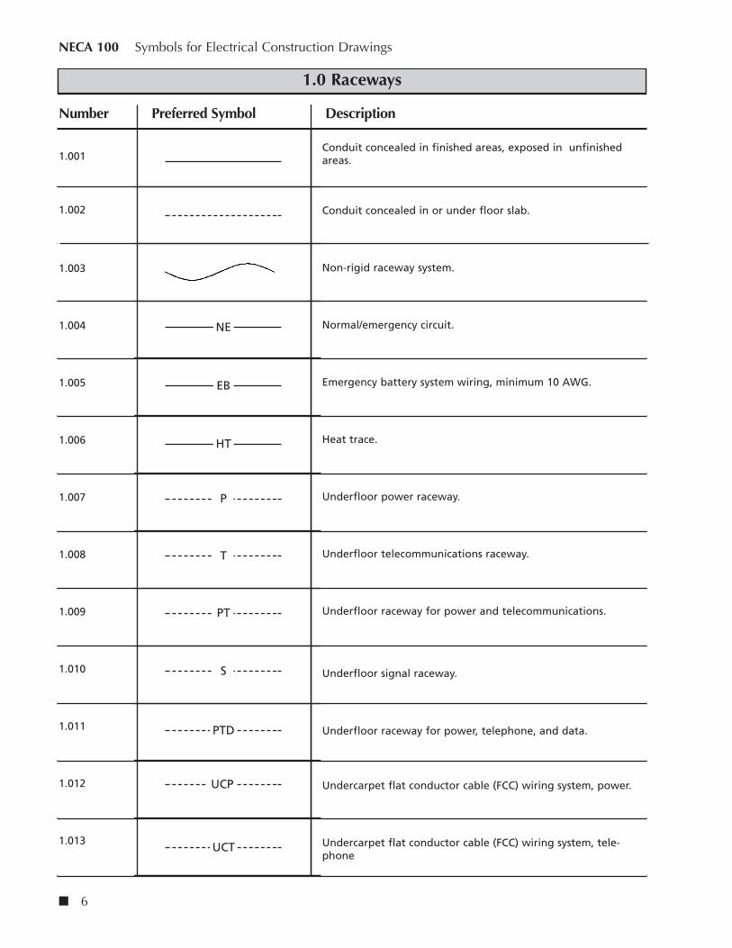
1.0 Raceways
1.001
1.002
1.003
1.004
1.005
1.006
1.007
1.008
1.009
1.010
1.011
1.012
1.013
Conduit concealed in finished areas, exposed in unfinishedareas.
Conduit concealed in or under floor slab.
Non-rigid raceway system.
Normal/emergency circuit.
Emergency battery system wiring, minimum 10 AWG.
Heat trace.
Underfloor power raceway.
Underfloor telecommunications raceway.
Underfloor raceway for power and telecommunications.
Underfloor signal raceway.
Underfloor raceway for power, telephone, and data.
Undercarpet flat conductor cable (FCC) wiring system, power.
Undercarpet flat conductor cable (FCC) wiring system, tele-phone
Number Preferred Symbol Description
NE
EB
HT
P
T
PT
S
PTD
UCP
UCT

1.101 Conduit stub. Terminate with bushing or cap if underground.
1.102 Conduit turning up.
1.103 Conduit turning down.
1.104 Indicates trade size 2” or 53 mm conduit with (4) 1 AWG and(1) 6 AWG ground.
1.105 Indicates (2) trade size 2” or 53 mm conduits with (4) 1 AWGand (1) 6 AWG ground conductors in each conduit.
1.106 Homerun to panelboard. Number of arrows indicates numberof circuits. (Example: Homerun to panel L211 CKTS. #1 and #3.)
1.107 Flexible connection to equipment.
1.108 Direct connection to equipment.
1.109 Branch circuit, full hashes indicate ungrounded-“hot” (orswitch-leg) circuit conductors. Half hashes indicates groundedneutral circuit conductors. (No hashes indicates 1 hot and 1neutral.) Dots indicate grounding conductors. Equipment bondsize U.N.O. “IG” indicates an isolated grounding conductor.
Number Preferred Symbol Description
NECA 100 Symbols for Electrical Construction Drawings
1.1 Raceways—Indicators
n 8
SZ 2C,4#1&1#6GND.
OR
SZ 53cm,4#1&1#6GND.
(2)SZ 2C,4#1&1#6GND.
OR
(2)SZ 53cm,4#1&1#6GND.
L211–1,3
IG

Symbols for Electrical Construction Drawings NECA 100
1.201 Underfloor raceway system junction box, flush floor mounted.
1.202 Power pole with devices indicated in the specifications and onthe drawing, “P” indicates type, “2” indicates circuit.
1.203 Telecom pole with devices indicated in the specifications andon the drawings, “T” indicates type.
1.204 Telecom/Power pole with devices indicated in the specificationsand on the drawings, “TP” indicates type, “2” indicates powercircuit.
1.205 Pull box—size as indicated or required.
1.206 Cabletray size as indicated.
1.207 Cabletray size as indicated, concealed.
1.208 Busway with cable tap box, rating and type as indicated ondrawings.
1.209 Busway with plug-in device as indicated, shown with fused dis-connect.
1.210 Busway feeding up.
1.211 Busway feeding down.
1.212 Busway expansion joint.
1.213 Wireway, size as indicated or required.
Number Preferred Symbol Description
9 n
1.2 Raceways—Boxes and Busways
J
P
2
T
TP
2
PB OR
TR TR TR
TR TR TR
BW BW BW
CTB
BW BW BW
F
BW
WW WW WW
NECA 100 Symbols for Electrical Construction Drawings
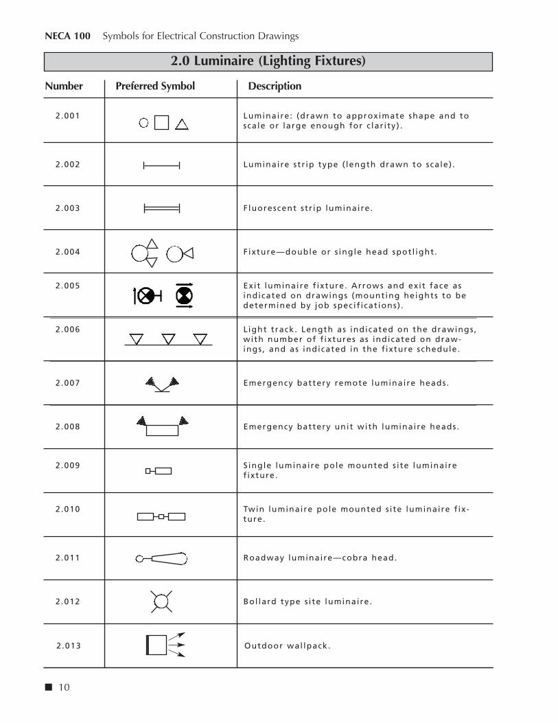
2.0 Luminaire (Lighting Fixtures)
Number Preferred Symbol Description
n 10
2.001 Luminaire: (drawn to approximate shape and toscale or large enough for c lar i ty) .
2 .002 Luminaire str ip type ( length drawn to scale) .
2 .003 Fluorescent str ip luminaire.
2.004 Fixture—double or s ingle head spotl ight.
2.005 Exit luminaire f ixture. Arrows and exit face asindicated on drawings (mounting heights to bedetermined by job specif icat ions) .
2 .006 Light track. Length as indicated on the drawings,with number of f ixtures as indicated on draw-ings, and as indicated in the f ixture schedule.
2.007 Emergency battery remote luminaire heads.
2.008 Emergency battery unit with luminaire heads.
2.009 Single luminaire pole mounted s i te luminairef ixture.
2.010 Twin luminaire pole mounted s i te luminaire f ix-ture.
2.011 Roadway luminaire—cobra head.
2.012 Bol lard type s i te luminaire.
2.013 Outdoor wal lpack.

11 n
Symbols for Electrical Construction Drawings NECA 100
2.1 Luminaire Fixtures—Basic Modifiers Mounting
2.2 Luminaire Fixtures—Basic Modifiers Orientation
Number Preferred Symbol Description
2.100 Surface mounted f ixture.
Recessed f ixture.
Wal l mounted f ixture.
Suspended, pendant, chain, stem or cable hungfixture.
Pole mounted with arm.
Pole mounted on top.
In-ground or f loor mounted. (Box around sym-bol . )
2 .200 Accent/direct ional arrow, with or without tai l .(Drawn from photometr ic center in direct ion ofoptics or photometr ic or ientat ion.)
Direct ional a iming l ine. (Drawn from photomet-r ic center and may be extended to actual a imingpoint i f required.)
Track mounted; length, luminaire types andquantit ies as shown. (Track length drawn toscale. )

Number Preferred Symbol Description
n 12
NECA 100 Symbols for Electrical Construction Drawings
2.3 Luminaire Fixtures—Emergency
2.4 Luminaire Fixtures—Extended Modifiers
2.300 Luminaire providing emergency i l lumination.(F i l led in. )
2 .401 Standard des ignations for a l l luminaire f ixtures .“A” = F ixture type, refer to f ixture schedule“NL” = Unswitched night l ight“2” = Circuit number“a” = Switch control
2.402 Mounting height.
2.403 Louvers .
2 .404 Recessed, emergency f ixture.
A A NL
a a2 2
+48”
NOTE: Modif iers are shown with specif ic base symbols for c lar i ty. Each modif ier can be used with any of the base symbols .

13 n
Symbols for Electrical Construction Drawings NECA 100
3.0 Outlets and Receptacles
3.001 Floor duplex receptacle. F=f lush MTD. S=surfaceMTD.
3.002 Duplex convenience receptacle. 20A 125V.
3 .003 Duplex convenience receptacle on emergency/stand-by c i rcuit . Specify panelboard and c ircuit .
3 .004 Single convenience receptacle.
3.005 Single convenience receptacle on emergency/stand-by c i rcuit . Specify panelboard and c ircuit .
3 .006 Double duplex convenience receptacle.
3.007 Double duplex convenience receptacle on emer-gency/standby c ircuit . Specify panelboard and c i r -cuit .
3 .008 Mult i -outlet assembly with outlets on centers asindicated on the drawings and in the specif icat ions,mounted 6" above counter or at height as directed,A - indicates type.
3.009 Mult ioutlet assembly, devices as indicated.
3.010 Special receptacle - typical notat ion:1— indicates example
“1” = __A, ___/___V. , _ Pole, _ Wire, _ NEMA __-__
“2” = __A, ___/___V. , _ Pole, _ Wire, _ NEMA __-__
“3” = __A, ___/___V. , _ Pole, _ Wire, _ NEMA __-__
3.011 Clock hanger outlet recessed mounted 8’ -0” AFF or8” below cei l ing as appropriate and as directed.
3.012 Flush mounted f loor box, adjustable, with bothpower and voice/data receptacles .
3 .013 Junct ion box. “AxBxC” indicates dimensions of junc-t ion box in either inches or centimeters .
Number Preferred Symbol Description
F
EP–2 CKT.1
EP–2 CKT.3
EP–2 CKT.5
A
1
1OR
F
1
J J
AxBxC

NECA 100 Symbols for Electrical Construction Drawings
3.0 Outlets and Receptacles
3.014 Duples receptacle cei l ing mounted 20A 125V.
3.015 Double duplex receptacle—cei l ing mounted.
Number Preferred Symbol Description
n 14
Receptacles And Outlets
Typical Outlet Notat ions:
“a” = Switched outlet , “a”—indicates switch control .
“B” = Pedestal mounted on bench top.
“BF” = Below f loor.
“C” = Mounted 6” above counter of 42” AFF. Coordinate exact mounting height witharchitectural drawings.
“CLG” = Cei l ing mounted.
“D” = Dedicated device on indiv idual branch c ircuit .
“E” = Emergency.
“EXIST.” = Exist ing device/equipment.
“F” = Flush f loor box with f i re /smoke rated penetrat ion.
“GFCI” = Ground fault c i rcuit interupter, personal protect ion.
“GFPE” = Ground fault protect ion of equipment.
“H” = Horizontal ly mounted.
“IG” = Isolated ground receptacle with separate green ground conductor to i solatedground bus in panel .
“M” = Modular furniture service—provide f lexible connect ion, coordinate exact loca-t ion with furniture plans.
“PED” = Pedestal mounted with two hour f i re /smoke rated penetrat ion.
“PT” = Poke thru with two hour f i re /smoke rated penetrat ion.
“S” = Surface mounted f loor box.
“SP” = Surge protect ion receptacle.
“T” = Tamper res istant safety receptacle.
“TL” = Twist- lock.
“W” = Wall mounted device at 48” AFF unless otherwise indicated.
“WP” = Weatherproof receptacle with “NRTL” l i s ted coverplate for wet locat ion withplug instal led. MTD. 48” AFF unless otherwise indicated.
+XX = Dimensioned height.
.

15 n
Symbols for Electrical Construction Drawings NECA 100
4.0 Switches and Sensors
4.001 Single pole switch.
4.002 Double pole switch.
4.003 Three way switch.
4.004 Four way switch.
4.005 Switch control ( lower case letter) .
4 .006 Circuit breaker switch.
4.007 Single pole/double throw switch.
4.008 Glow switch toggle, glows in off posit ion.
4.009 Horizontal ly mounted—with on posit ion to the left .
4 .010 Key operated switch.
4.011 Key operated switch with pi lot l ight on whenswitch i s on.
4.012 Low voltage switch.
4.013 Low voltage master switch.
Number Preferred Symbol Description
$ or S
$2 or S2
$3 or S3
$4 or S4
$a or Sa
$CB or SCB
$DT or SDT
$G or SG
$H or SH
$K or SK
$KP or SKP
$LV or SLV
$LM or SLM
e it.

Symbols for Electrical Construction Drawings NECA 100
5.0 Motorized and HVAC Equipment—Controls
5.001 Disconnect switch, unfused type, s ize as indicatedon drawings. “xxA” indicates amperage.
5.002 Disconnect switch, fused type, s ize as indicated ondrawings. “xxAF” indicates frame s ize. “xxAT” indi-cates tr ip s ize.
5.003 Enclosed c ircuit breaker, s ize as indicated. “xxAF”indicates frame s ize. “xxAT” indicates tr ip s ize.
5.004 Magnetic contactor, s ize as indicated on drawings.
5.005 Adjustable speed dr ive.
5.006 Motor starter switch.
5.007 Magnetic motor starter. “RV” indicates reducedvoltage. Starter s ize as indicated.
5.008 Combination magnetic starter and disconnectswitch. Starter s ize and fuse rat ing as indicated.
5.009 Automatic temperature control panel .
5 .010 Equipment control panel .
5 .011 Relay.
5.012 Toggle disconnect switch.
5.013 Thermal motor switch with handle guard and pad-lock capabi l i ty. “P”—indicates pi lot l ight .
Number Preferred Symbol Description
17 n
xxA
FxxAFyyAT
CBxxAFyyAT
C
ASD
$M
RV
NEMA x
F
NEMA xxxA–xP
ATC
CP
R
TD
TS P

NECA 100 Symbols for Electrical Construction Drawings
5.1 Motorized and HVAC Equipment
5.101 Capacitor.
5 .102 Motor “3”—indicates horsepower.
5.103 Motorized damper.
5.104 Baseboard heater.
5 .105 Baseboard heater with box.
5.106 Resistance heater.
5 .107 Unit type heater.
5 .108 Cei l ing fan.
5.109 Paddle fan.
5.110 Wall fan.
5.111 Water heater.
Number Preferred Symbol Description
n 20
3
D
WH

Symbols for Electrical Construction Drawings NECA 100
7.0 Fire Alarm Communications and Panels
7.001 Fire alarm master box.
7.002 Fire f ighter ’s phone.
7.003 Coded transmitter.
7 .004 Dri l l key switch.
7.005 Key repository (knox box) .
7 .006 Annunciator panel .
7 .007 Fire alarm control panel .
7 .008 Voice evacuation panel .
7 .009 Fire alarm terminal cabinet .
7.010 Battery pack and charger.
7.011 Air sampl ing control /detector panel with associatedair sampl ing piping network.
7.012 Transponder.
7.013 Indiv idual addressable module.
Number Preferred Symbol Description
23 n
M
FT
DK
K
FAA
FACP
EVAC
FATC
BATT
ASFP
TPR
IAM

NECA 100 Symbols for Electrical Construction Drawings
8.0 Power Distribution Equipment
8.001 Lighting or power panel , recessed.
8.002 Lighting or power panel , surface.
8.003 Distr ibution panel .
8 .004 Lighting or power panel on normal /generatorfeeder.
8.005 Distr ibution panel on normal /generator feeder.
8.006 Motor control center.
8 .007 Dry type transformer, refer to transformer schedule,“T45”—indicates transformer type f loor mounted.Unless otherwise indicated, “W”—indicates wal l ,“S”—indicates suspended. “R”—indicates K rat ing.
8.008 Transformer—pad mount.
8.009 Current transformer cabinet .
8.010 Generator. S ize as noted.
8.011 Meter—single.
8.012 Meter and socket.
8.013 Transfer switch. “TS”=manual transfer switch.“ATS”=automatic transfer switch.
Number Preferred Symbol Description
n 28
XFMR NUMBER
MCC
T
T45-1
T
CT
xxkW
M
M
TS
G

n 32
NECA 100 Symbols for Electrical Construction Drawings
10.0 Site Work
10.001 Underground feeder.
10.002 Underground telephone.
10.003 Underground f i re alarm.
10.004 Underground televis ion (CATV).
10.005 Above ground pole mounted electr ical .
10.006 Above ground pole mounted telephone.
10.007 Above ground pole mounted f i re alarm.
10.008 Above ground pole mounted televis ion (CATV).
10.009 Manhole.
10.010 Handhole.
10.011 Uti l i ty pole. “Pxxxx” indicates pole number.
10.012 Combination pre-fabricated manholes for power and tel /data systems. “E” = denotes power, “T” = denotes tel /data.
10.013 “J” hook.
Number Preferred Symbol Description
UF
E
UT
UFA
UTV
T
F
TV
HH
ET
MH
PxxxxP

33 n
Symbols for Electrical Construction Drawings NECA 100
11.0 Schematic and One-line Diagram Symbols
11.001 Capacitor.
11.002 Circuit breaker (open) . “xxAF” indicates frame s ize.“yyAT” indicates tr ip s ize.
11.003 Circuit breaker (enclosed) . “xxAF indicates framesize. “yyAT” indicates tr ip s ize.
11.004 Primary draw out type c ircuit breaker. “xxAF” indi-cates frame s ize. “yyAT” indicates tr ip s ize.
11.005 Low voltage draw out type c ircuit breaker. “xxAF”indicates frame s ize. “yyAT” indicates tr ip s ize.
11.006 Low voltage draw out type circuit breaker with cur-rent limiting fuses. “xxAF” indicates frame size.“yyAT” indicates trip size. “zzA” indicates fuse rating.
11.007 Contact , normal ly open (NO) (“TC”—with t imedclos ing) .
11.008 Contact , normal ly c losed (NC) . (“TO”—with t imedopening) .
11.009 Current transformer cabinet .
11.010 Fused cutout. “zzA” indicates fuse rat ing.
11.011 Disconnect switch unfused.
11.012 Disconnect switch air break with fuse. “zzA” indi -cates fused rat ing.
11.013 Fuse. “zzA” indicates fuse rat ing.
Number Preferred Symbol Description
xxAFyyAT
xxAFyyAT
xxAFyyAT
xxAFyyAT
xxAFyyAT
zzA
CT
zzA
zzA
zzA
zzA

n 34
NECA 100 Symbols for Electrical Construction Drawings
11.0 Schematic and One-line Diagram Symbols
11.014 Overload relay.
11.015 Grounding connect ion—system and or equipment.
11.016 Kirk key inter lock system. “2”—indicates relatedkirk keys .
11.017 Lightning arrester and grounding to protect a l lphases .
11.018 Motor and label . “3” denotes horsepower.
11.019 Motor operator for c i rcuit breakers or switches.
11.020 Network protector.
11.021 Panelboard.
11.022 Pothead.
11.023 Stress cone.
11.024 Resistor.
11.025 Shunt tr ip.
11.026 Magnetic starter with NEMA size indicated.
Number Preferred Symbol Description
K2
xx-xx-x-x
MO
PANEL
tt
ST
1
3
p licen
se to
rem
ove
it.

35 n
Symbols for Electrical Construction Drawings NECA 100
11.0 Schematic and One-line Diagram Symbols
11.027 Ground fault c i rcuit interrupter, personnel protec-t ion.
11.028 Generator.
11.029 Transformer, dry type. Unless otherwise indicated.
11.030 Potential transformer. “3”—indicates quantity.
11.031 Current transformer. “3”—indicates quantity, “400-5A” indicates rat io.
11.032 3-phase, 3-wire delta connect ion.
11.033 Corner grounded delta.
11.034 3-phase, 4-wire wye connect ion (grounded neutral ) .
11.035 Adjustable frequency dr ive. 3 references detai l number.
11.036 Busduct or busway.
11.037 Wireway.
Number Preferred Symbol Description
GFCI
ttGxxx KWxxxV-xø
GENERATOR
OOOOOOOO
tt
Tx
xxx KVAxxxV xø xW PRI
xxxY/xxxV xø xW SEC
(3)
OO
AFDxx-x-x
OO
(3)
400-5A
3
XX’ xxxV BUSDUCT
XX’ xxxV WIREWAY

n 38
NECA 100 Symbols for Electrical Construction Drawings
11.2 Schematic and One-line Diagram Symbols—Switches
11.201 Transfer switch.
11.202 Push button (start) .
11.203 Push button (stop) .
11.204 Limit switch.
11.205 Flow switch.
11.206 Pressure switch.
11.207 Float switch.
11.208 Pi lot l ight . Letter indicates color. Example: R=red.
11.209 Solenoid.
Number Preferred Symbol Description
N
L
EAUTO/MANUALTRANSFER SWTICHxxA-xP
R
p licen
se to
rem
ove
it.

39 n
Symbols for Electrical Construction Drawings NECA 100
12.0 Miscellaneous
12.001 Ground bar. Length to be noted.
12.002 Mechanical equipment tag number, refer tomechanical equipment schedule.
12.003 Equipment tag number, refer to equipment sched-ule, “K”—indicates k itchen, “C”—indicates comput-er.
12.004 Note symbol , refer to note as indicated.
12.005 Feeder number, refer to “feeder schedule”.
12.006 Typical / s imi lar room or area layout symbol . “A”—indicates layout type.
12.007 Typical layout symbol—refer to layout type. “A” ondrawing E-2, c i rcuits to be used are as indicated.
12.008 Detai l header, indicat ing detai l No. 2 on drawing E-4.
12.009 Sect ion identif ier, indicat ing sect ion “B” on draw-ing E-2. Left or r ight arrow.
12.010 Detai l identif ier, indicat ing detai l No. 2 on drawingE-4.
Number Preferred Symbol Description
G
AC
2
K2
B
1
A
DESCRIPTIONSCALE: N.T.S.
AE–2
CKT/ P21–5,7
2
E–4 t
B
E–2
2
E–4
t

n 40
NECA 100 Symbols for Electrical Construction Drawings
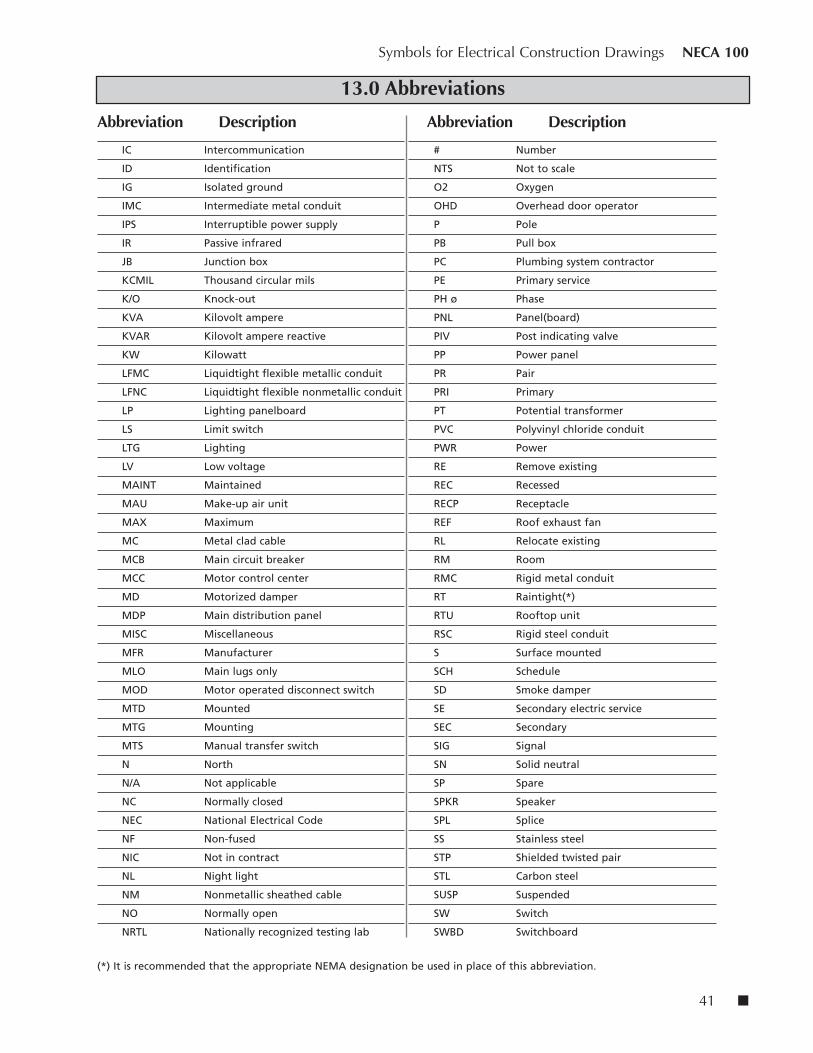
13.0 Abbreviations
Abbreviation Description Abbreviation Description
1P One pole
2P Two pole
3P Three pole
4P Four pole
1P1W One pole, one wire
1P2W One pole, two wire
2P2W Two pole, two wire
2P3W Two pole, three wire
3P2W Three pole, two wire
3P3W Three pole, three wire
3P4W Three pole, four wire
4P4W Four pole, four wire
A Ampere
AC Alternating current
AF AMP frame
AFCI Arc-fault circuit interrupter
AFF Above finished floor
AFG Above finished grade
AHU Air handling unit
AIC Ampere interrupting capacity
AL Aluminum
AS AMP switch
AT AMP trip
ARCH Architect
ATS Automatic transfer switch
AUD Audiometer box connection
AUX Auxiliary
A / V Audio visual
AWG American wire gauge
BLDG Building
C Conduit (Generic term for raceway.
Provide as specified.)
CAM Camera
CAT Catalog
CATV Cable television
CB Circuit breaker
CKT Circuit
COL Column
C.T. Current transformer
CU Copper
Centerline
DC Direct Current
Delta
DET Detector
DISC Disconnect
DIST Distribution
DN Down
DWG Drawing
DT Dusttight(*)
E Wired on emergency circuit
EA Each
EC Electrical contractor
EF Exhaust fan
ELEC Electric(al)
EMER Emergency
EMT Electric metallic tubing
ENCL Enclosure
EOL End of line
EPO Emergency power off
EQUIP Equipment
EWC Electric water cooler
EWH Electric water heater
EXIST. Existing
F Flush
FA Fire alarm
FBO Furnished by others
FC Fire protection contractor
FCU Fan coil unit
FDN Foundation
FIXT Fixture
FLA Full load amps
FLEX Flexible
FLR Floor
FMC Flexible metallic conduit
FRE Fiberglass reinforced epoxy conduit
FURN Furniture
GC General contractor
GEN Generator
GFCI Ground fault circuit interrupter
GFPE Ground fault protection equipment
GND Grounded
GRC Galvanized rigid conduit
HGT Height
HP Horsepower
HV High voltage
HVAC Heating, ventilating and air
conditioning
HW Hot water
Hz Hertz (cycle) per second
IAM Individual addressable module
CL
41 n
Symbols for Electrical Construction Drawings NECA 100
13.0 Abbreviations
Abbreviation Description Abbreviation Description
IC Intercommunication
ID Identification
IG Isolated ground
IMC Intermediate metal conduit
IPS Interruptible power supply
IR Passive infrared
JB Junction box
KCMIL Thousand circular mils
K/O Knock-out
KVA Kilovolt ampere
KVAR Kilovolt ampere reactive
KW Kilowatt
LFMC Liquidtight flexible metallic conduit
LFNC Liquidtight flexible nonmetallic conduit
LP Lighting panelboard
LS Limit switch
LTG Lighting
LV Low voltage
MAINT Maintained
MAU Make-up air unit
MAX Maximum
MC Metal clad cable
MCB Main circuit breaker
MCC Motor control center
MD Motorized damper
MDP Main distribution panel
MISC Miscellaneous
MFR Manufacturer
MLO Main lugs only
MOD Motor operated disconnect switch
MTD Mounted
MTG Mounting
MTS Manual transfer switch
N North
N/A Not applicable
NC Normally closed
NEC National Electrical Code
NF Non-fused
NIC Not in contract
NL Night light
NM Nonmetallic sheathed cable
NO Normally open
NRTL Nationally recognized testing lab
# Number
NTS Not to scale
O2 Oxygen
OHD Overhead door operator
P Pole
PB Pull box
PC Plumbing system contractor
PE Primary service
PH ø Phase
PNL Panel(board)
PIV Post indicating valve
PP Power panel
PR Pair
PRI Primary
PT Potential transformer
PVC Polyvinyl chloride conduit
PWR Power
RE Remove existing
REC Recessed
RECP Receptacle
REF Roof exhaust fan
RL Relocate existing
RM Room
RMC Rigid metal conduit
RT Raintight(*)
RTU Rooftop unit
RSC Rigid steel conduit
S Surface mounted
SCH Schedule
SD Smoke damper
SE Secondary electric service
SEC Secondary
SIG Signal
SN Solid neutral
SP Spare
SPKR Speaker
SPL Splice
SS Stainless steel
STP Shielded twisted pair
STL Carbon steel
SUSP Suspended
SW Switch
SWBD Switchboard
(*) It is recommended that the appropriate NEMA designation be used in place of this abbreviation.

n 42
NECA 100 Symbols for Electrical Construction Drawings
13.0 Abbreviations
Abbreviation Description Abbreviation Description
SWGR Switchgear
TC Telephone cabinet
TCI Telecommunications cabling installer
TCP Temperature control panel
TEL/DATA Telephone/data
TEL Telephone TEMP Temporary
TERM Terminal(s)
TV Television
TYP Typical
UC Under counter
UG Underground
UH Unit heater
U.O.I. Unless otherwise indicated
UPS Uninterruptible power source
UTIL Utility
UTP Unshielded twisted pair
V Volt
VT Vaportight(*)
Y Wye
W Watt
W/ With
WH Watthour
WP Weatherproof
WP Weatherproof
WT Watertight(*)
XFMR Transformer
XP Explosion proof(*)
ZAM Zone adapter module
+72 Mounting units to centerline above
finished floor or grade

n 48
This annex provides examples of typical schedules, riser diagrams, and one-line diagrams that are included inelectrical construction drawings. A given set of drawings will not necessarily include every typical exampleincluded here. This annex includes the following:
Type Page
Panel schedule . . . . . . . . . . . . . . . . . . . . . . . 49
Lighting fixture schedule . . . . . . . . . . . . . . . 50
Transformer schedule . . . . . . . . . . . . . . . . . 51
Mechanical equipment schedule. . . . . . . . . 52
Feeder schedule . . . . . . . . . . . . . . . . . . . . . . 53
Electrical one-line diagram . . . . . . . . . . . . . 54
Fire alarm riser . . . . . . . . . . . . . . . . . . . . . . . 55
Annex B: Typical Risers, One-lineDiagrams, and Schedules
licen
se to
rem
ove
it.

49 n
Pan
el:
____
____
____
_
V
olt
age:
___
____
____
____
____
Ph
ase:
___
____
____
__
W
ires
: __
____
____
_
M
ain
s: _
____
____
____
____
____
____
_
Mo
un
t: _
____
____
____
____
____
__
E
ncl
osu
re:
____
____
____
____
____
____
__
L
oca
tio
n:
____
____
____
____
____
____
____
____
____
____
____
___
Load
Bkr
.C
kt.
Ckt
.B
kr.
Load
Load
Nam
e(V
A)
Fram
eTr
ipN
o.
AB
CN
o.
Trip
Fram
e(V
A)
Load
Nam
e
12
34
56
78
910
1112
1314
1516
1718
1920
2122
2324
2526
2728
2930
3132
3334
3536
3738
3940
4142
Phas
e A
: __
____
____
____
____
___
Phas
e B
: __
____
____
____
____
___
Ph
ase
C:
____
____
____
____
____
_
To
tal
VA
: __
____
____
____
____
____
__
Mfg
./Typ
e: _
____
____
____
____
____
___
Mo
dif
icat
ion
s: _
____
____
____
____
____
____
_
A
mp
s R
MS.
Sym
.: _
____
____
____
____
____
____
____
___
Pan
el S
ched
ule
chea
p lic
ense
to re
mov
e it.

n 50
Typ
eM
anu
fact
ure
rC
atal
og
No
.D
escr
ipti
on
Mo
un
tin
gLa
mp
s
Lig
hti
ng
Fix
ture
Sch
edu
le

51 n
PRI.
Sec.
Gro
un
dC
atal
og
Co
nd
uct
or
Sec.
Co
nd
uct
or
Co
nd
uct
or
Des
ign
atio
nM
anu
fact
ure
rN
um
ber
KV
Aø
PRI.
Vo
lts
Size
/No
.V
olt
sSi
ze/N
o.
Size
/No
.M
ou
nti
ng
Tran
sfo
rmer
Sch
edu
le

n 52
Min
.M
ax.
Min
.R
emar
ks/
Wir
eFu
seC
CT
Dis
con
nec
tD
esig
nat
ion
Des
crip
tio
nQ
uan
tity
Vo
ltø
FLA
HP
KV
ASi
ze/T
ype
Size
Am
ps
Typ
e
Mec
han
ical
Eq
uip
men
t Sc
hed
ule

53 n
No. No. Runs No. Wires/Size Insul. CU/AL Conduit Origin Termination
Feeder Schedule#

n 54
Electrical One-Line Diagram
FROM EMERG.SWITCHGEAR3EH01B6
3EHA1B6B 1200A 480V, 3W+G, 3P 65,000A RMS SYM CLOSINGAND WITHSTAND RATING
FROM 480VUNIT SUBSTATION #8
1200AEMERGENCY DISTRIBUTION SWITCHBOARD3EH01C6B, 1200A, 480V, 3Ø, 3W+G, 65,000 IER
1
600A800A 800A
800A
240A 400A 240A
EMERGENCY DISTRIBUTION SWITCHBOARD3EHM8D8B, 800A, 480V, 3Ø, 3W+G, 65,000 IER
250/M
RVNR22,000 IER
125
C-26-1-1
AFD36-2-2
250
F-36-2-2
150
P-32-5-2
AFD32-5-2
150A
3EHT18575 KVA480V 3Ø 3W PRI
120/208V 3Ø 4W SEC
3EHL1B5
OOOOOOOO
tt
800 EMERGENCY DISTRIBUTION SWITCHBOARD3EHM1D4B, 800A, 480V, 3Ø, 3W+G, 65,000 IER
300A
AFD32-2-2
150
EF-32-2-2
240A
AFD32-2-4
125
EF-32-2-4
240A 240A
SPARE SPARE
1 3
1 2
2 3 4
9
10 11
5 6
600 EMERGENCY DISTRIBUTION SWITCHBOARD3EHM1D4D, 600A, 480V, 3Ø, 3W+G, 65,000 IER
240A
AFD32-2-8
125
EF-32-2-8
240A
AFD32-2-10
125
EF-32-2-10
240A
SPARE
1 3
7 8
N EL
125A
SPARE
4
5
NECA 100 Symbols for Electrical Construction Drawings