Embed Size (px)
Citation preview
American Bonanza Society Air Safety Foundation
Flight Controls, Flaps and Trim System Inspection,
Repair and Rigging Guide
For Beechcraft Bonanza, Debonair, Baron and Travel Air
© 2011 ABS Air Safety Foundation www.bonanza.org

© 2011 ABS Air Safety Foundation www.bonanza.org
2
American Bonanza Society Air Safety Foundation
Flight Controls, Flaps and Trim System Inspection, Repair and Rigging Guide
Written by Ron Sanow
Edited by Thomas P. Turner
Additional editing and technical assistance by
Neil Pobanz, ABS lead technical advisor
Glen “Arky” Foulk
Richard H. Pedersen
Robert M. Olson
Arthur G. Miller
Robert G. Ripley
Robert E. Andrews
Tom Rosen
Stuart Spindel
Dave Monti
2010-2011 ABS Technical Committee
Tom Rosen, chairman
Ward Combs
Thomas P. Turner, Executive Director, ABS Air Safety Foundation
J. Whitney Hickman, Executive Director, American Bonanza Society
Lorne Sheren, M.D., President
For educational purposes only. Refer to manufacturers data for all specifications. In the event of any contradiction the
manufacturer's data takes precedence.
© 2011 ABS Air Safety Foundation www.bonanza.org
3
American Bonanza Society Air Safety Foundation
Flight Controls, Flaps and Trim System Inspection, Repair and Rigging Guide
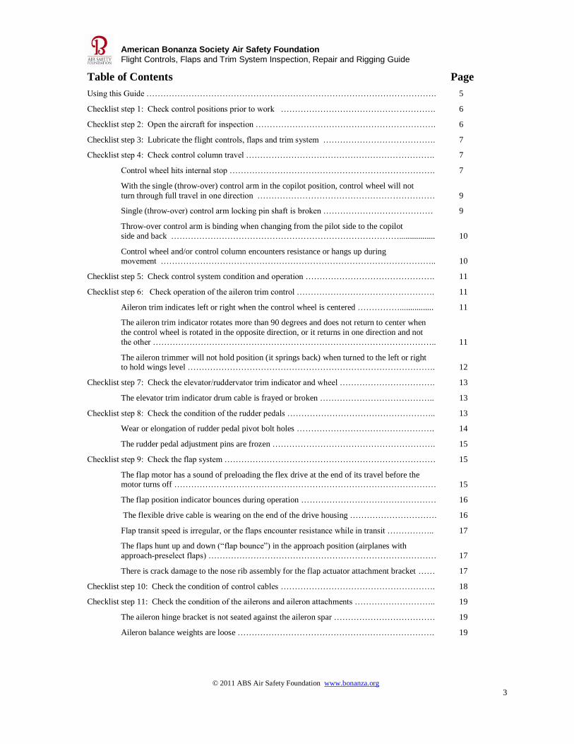
Table of Contents Page
Using this Guide …………………………………………………………………………………………. 5
Checklist step 1: Check control positions prior to work ………………………………………………. 6
Checklist step 2: Open the aircraft for inspection ………………………………………………………. 6
Checklist step 3: Lubricate the flight controls, flaps and trim system …………………………………. 7
Checklist step 4: Check control column travel …………………………………………………………. 7
Control wheel hits internal stop ………………………………………………………………. 7
With the single (throw-over) control arm in the copilot position, control wheel will not
turn through full travel in one direction ……………………………………………………… 9
Single (throw-over) control arm locking pin shaft is broken ………………………………… 9
Throw-over control arm is binding when changing from the pilot side to the copilot
side and back ………………………………………………………………………................. 10
Control wheel and/or control column encounters resistance or hangs up during movement …………………………………………………………………………………….. 10
Checklist step 5: Check control system condition and operation ………………………………………. 11
Checklist step 6: Check operation of the aileron trim control …………………………………………. 11
Aileron trim indicates left or right when the control wheel is centered ……………................ 11
The aileron trim indicator rotates more than 90 degrees and does not return to center when
the control wheel is rotated in the opposite direction, or it returns in one direction and not
the other ……………………………………………………………………………………….. 11
The aileron trimmer will not hold position (it springs back) when turned to the left or right to hold wings level ……………………………………………………………………………. 12
Checklist step 7: Check the elevator/ruddervator trim indicator and wheel ……………………………. 13
The elevator trim indicator drum cable is frayed or broken ………………………………….. 13
Checklist step 8: Check the condition of the rudder pedals …………………………………………….. 13
Wear or elongation of rudder pedal pivot bolt holes …………………………………………. 14
The rudder pedal adjustment pins are frozen …………………………………………………. 15
Checklist step 9: Check the flap system ………………………………………………………………… 15
The flap motor has a sound of preloading the flex drive at the end of its travel before the motor turns off ………………………………………………………………………………… 15
The flap position indicator bounces during operation ………………………………………… 16
The flexible drive cable is wearing on the end of the drive housing …………………………. 16
Flap transit speed is irregular, or the flaps encounter resistance while in transit …………….. 17
The flaps hunt up and down (“flap bounce”) in the approach position (airplanes with
approach-preselect flaps) ……………………………………………………………………… 17
There is crack damage to the nose rib assembly for the flap actuator attachment bracket …… 17
Checklist step 10: Check the condition of control cables ………………………………………………. 18
Checklist step 11: Check the condition of the ailerons and aileron attachments ……………………….. 19
The aileron hinge bracket is not seated against the aileron spar ……………………………… 19
Aileron balance weights are loose ……………………………………………………………. 19
© 2011 ABS Air Safety Foundation www.bonanza.org
4
American Bonanza Society Air Safety Foundation
Flight Controls, Flaps and Trim System Inspection, Repair and Rigging Guide
Table of Contents (continued) Page
The aileron push-pull rod is binding, and is not rotating side-to-side ………………………… 20
The aileron aft push-pull rod end is worn, giving excessive vertical movement on the
aileron trailing edge …………………………………………………………………………… 20
The aileron forward push-pull rod end is worn at the bell crank, giving excessive vertical movement on aileron trailing edge ……………………………………………………………. 21
The aileron bell crank stops do not contact the stops in both wings ………………………….. 22
Corrosion on a magnesium control surface …………………………………………………… 22
Checklist step 12: Check the aileron cable routing in the main wheel wells …………………………… 23
A control cable is chafing on a rib or component …………………………………………….. 23
Checklist step 13: Check the aileron trim tab …………………………………………………………… 23
There is excessive vertical play at the trailing edge of the trim tab …………………………… 24
Checklist step 14: Check the flaps ………………………………………………………………………. 24
A flap actuator is leaking fluid out of the end of the housing, around the piston shaft ……….. 25
The flap skin is cracked at the flap actuator attach bracket …………………………………… 26
A flap bumper is loose or a bumper nut plate is broken ………………………………………. 28
The flap is not centered on flap tracks, with side-to-side movement of the flap ……………… 28
Checklist step 15: Check the Model 35 (V-tail) pitch trim actuator ……………..……………………… 28
Checklist step 16: Check the Model 35 (V-Tail) differential control mechanism ……………………….. 28
Rudder and elevator combined movement will not make full travel …………………………... 28
One ruddervator push-pull rod is noticeably shorter than the other ……………………………. 30
Checklist step 17: Check the Model 33, 36, Baron and Travel Air elevator bell crank ………………….. 31
The left and right elevator trailing edges move up and down independently when pressure
is applied ………………………………………………………………………………………… 31
Checklist step 18: Check the Model 33, 36, Baron and Travel Air rudder and hinge attach areas ………. 31
Cracks appear along the rudder spar hinge line ………………………………………………… 31
Checklist step 19: Check the Baron and Travel Air rudder trim ………………………………………….. 32
The Baron/Travel Air rudder trim actuator has excessive free play …………………………….. 32
The rudder trim actuator drive chain is binding …………………………………………………. 33
Checklist step 20: Check the condition of the ruddervators/elevators and trim ……………………………. 33
The trim tabs are installed incorrectly …………………………………………………………… 33
There is excessive movement or wear in the hinge bearings ……………………………………. 33
Checklist step 21: Check the pitch trim tabs, actuators and cables ………………………………………… 36
The Model 33, 36, Baron and Travel Air elevator trim binds, or the electric trim is slow and
hangs up under a load …………………………………………………………………………….. 36
There is excessive trim tab end play ……………………………………………………………… 37
V-tail aircraft does not have enough nose-down trim for descent ………………………………... 38
Appendix A: Treating magnesium surfaces ………………………………………………………………… 39
Appendix B: Addressing a wing-heavy condition ………………………………………………………….. 41
© 2011 ABS Air Safety Foundation www.bonanza.org
5
American Bonanza Society Air Safety Foundation
Flight Controls, Flaps and Trim System Inspection, Repair and Rigging Guide
Using this Guide
Inspection, maintenance, repair and rigging of Beechcraft flight controls, flaps and trim systems is addressed
very well in the manufacturer’s Maintenance and Shop manuals. This Guide is meant as a supplement to
Beechcraft publications, to fill in the gaps for mechanics not completely familiar with the
Bonanza/Debonair/Baron/Travel Air airplanes. It is the result of ABS’ Technical Advisors’ decades of
experience maintaining Beech piston aircraft, and thousands of airplanes inspected through the ABS Air
Safety Foundation Service Clinic program.
It’s imperative to have access to and use the Beechcraft Maintenance or Shop Manual for the specific serial
number airplane when performing work on the flight controls, flaps and/or trim system. At all times, if there
is a discrepancy between this Guide and specific guidance in Beechcraft publications, the manufacturer’s
information takes precedence.
© 2011 ABS Air Safety Foundation www.bonanza.org
6
American Bonanza Society Air Safety Foundation
Flight Controls, Flaps and Trim System Inspection, Repair and Rigging Guide
1. Check control position prior to beginning work
At the beginning of an inspection note the position of the control surfaces, so if you adjust
cable tensions or replace worn rod ends the flight characteristics are not changed. If aircraft
rigging is in question, a walk-around of the aircraft, reviewing and noting the position of the
control surfaces, and a conversation with the pilot about how the aircraft is flying is helpful.
Things to ask:
1. Does the control wheel remain level in flight if the wheel is level on the ground with
the ailerons aligned straight? If not, the wing angle of incidence may need to be
adjusted.
2. Is the turn coordinator ball centered in straight-and-level flight?
3. Does aircraft drift off heading?
4. Will the airplane stay in a shallow-bank turn without getting steeper or returning to
level flight?
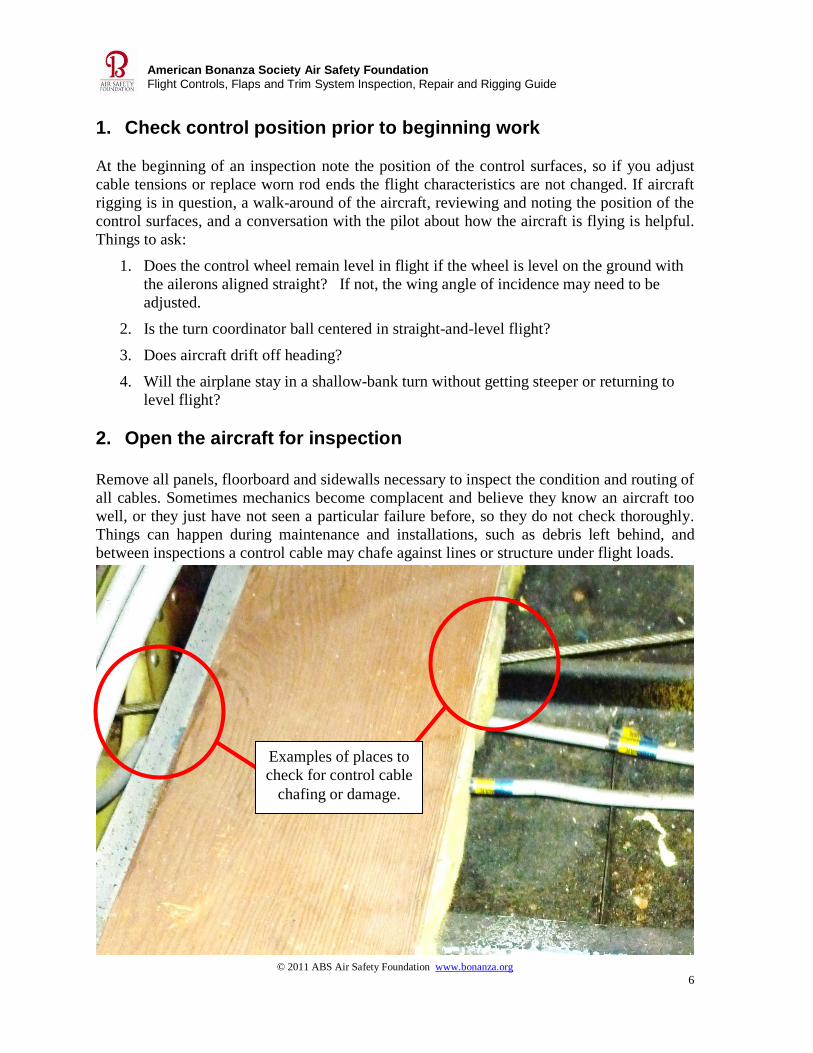
2. Open the aircraft for inspection
Remove all panels, floorboard and sidewalls necessary to inspect the condition and routing of
all cables. Sometimes mechanics become complacent and believe they know an aircraft too
well, or they just have not seen a particular failure before, so they do not check thoroughly.
Things can happen during maintenance and installations, such as debris left behind, and
between inspections a control cable may chafe against lines or structure under flight loads.
Examples of places to
check for control cable
chafing or damage.

© 2011 ABS Air Safety Foundation www.bonanza.org
7
American Bonanza Society Air Safety Foundation
Flight Controls, Flaps and Trim System Inspection, Repair and Rigging Guide
Tip: Lubricate the flight controls, flap, trim tabs, and exposed rod ends immediately after any time the aircraft is
washed.
3. Lubricate the flight control, flaps and trim system
Thoroughly lubricate the flight control, flaps and trim systems per the Beech maintenance or
shop manual and the Handling, Servicing and Maintenance section of the Pilot’s Operating
Handbook appropriate to the specific airplane. The importance
of lubrication cannot be overstated to decrease wear, increase the
life of parts, and reduce overall costs. Regardless, proper
lubrication is often overlooked by mechanics and aircraft owners.
Flight control pivot points and especially any areas exposed to
the environment, bell cranks without bushings, clevises and rod
ends need frequent lubrication. Where Beech does not call for
specific lubricants, LPS 2 is a good product that penetrates, displaces moisture, is non-
drying, and can be used to eliminate wear and binding.
4. Check control column travel
Discrepancy: Control wheel hits column internal stop
If the control wheel hits
the internal stop before
the ailerons hit the stops
in the wing, or if the
control torque knee is not
centered when the control
yoke is centered, the
system is out of rig.
When the control wheel is
level the ailerons should
align with the wing tips
and retracted flap trailing
edge.
1. Remove the flight
control arm by
removing the four
screws on the split
attach ring.
2. Center the aileron
torque knee to the
12o’clock
position.
Aileron torque knee
© 2011 ABS Air Safety Foundation www.bonanza.org
8
American Bonanza Society Air Safety Foundation
Flight Controls, Flaps and Trim System Inspection, Repair and Rigging Guide
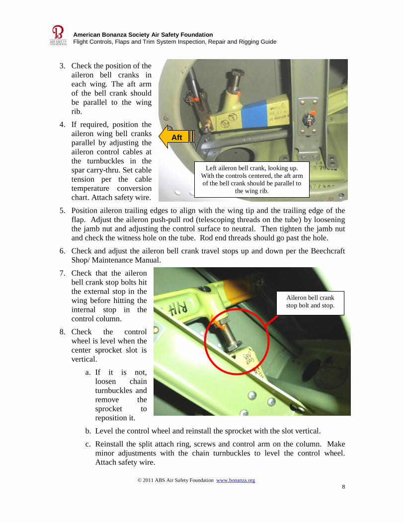
3. Check the position of the
aileron bell cranks in
each wing. The aft arm
of the bell crank should
be parallel to the wing
rib.
4. If required, position the
aileron wing bell cranks
parallel by adjusting the
aileron control cables at
the turnbuckles in the
spar carry-thru. Set cable
tension per the cable
temperature conversion
chart. Attach safety wire.
5. Position aileron trailing edges to align with the wing tip and the trailing edge of the
flap. Adjust the aileron push-pull rod (telescoping threads on the tube) by loosening
the jamb nut and adjusting the control surface to neutral. Then tighten the jamb nut
and check the witness hole on the tube. Rod end threads should go past the hole.
6. Check and adjust the aileron bell crank travel stops up and down per the Beechcraft
Shop/ Maintenance Manual.
7. Check that the aileron
bell crank stop bolts hit
the external stop in the
wing before hitting the
internal stop in the
control column.
8. Check the control
wheel is level when the
center sprocket slot is
vertical.
a. If it is not,
loosen chain
turnbuckles and
remove the
sprocket to
reposition it.
b. Level the control wheel and reinstall the sprocket with the slot vertical.
c. Reinstall the split attach ring, screws and control arm on the column. Make
minor adjustments with the chain turnbuckles to level the control wheel.
Attach safety wire.
Left aileron bell crank, looking up.
With the controls centered, the aft arm
of the bell crank should be parallel to
the wing rib.
Aft
Aileron bell crank
stop bolt and stop.
© 2011 ABS Air Safety Foundation www.bonanza.org
9
American Bonanza Society Air Safety Foundation
Flight Controls, Flaps and Trim System Inspection, Repair and Rigging Guide
Discrepancy: With the single (throw-over) control arm in the copilot position, the
control wheel will not turn through full travel in one direction
This situation usually results when the turnbuckles are significantly off center and are hitting
a control wheel sprocket prior to reaching full travel. Return the single control arm to the
pilot position. Check the chain turnbuckle location. It should be centered in the inspection
port. If it is not, the chain will need to be repositioned:
1. Remove the control arm by removing the four screws on the split attach ring.
2. Remove the chain turnbuckle safety wire, then loosen the chain.
3. Remove the control wheel adapter cotter pin and nut.
4. Lightly tap the adapter out of the chain sprocket.
5. Reposition the control arm sprockets to center chain turnbuckles in inspection port.
6. With the control wheel adapter sprocket keyway in the 12 o’clock position, install the
center sprocket slot so it is vertical with the control arm level. (Align the chain to the
yellow index marks if they are still on the chain and sprockets).
7. Install the control wheel or control wheel adapter keyed into the sprocket. Check that
turnbuckles are in the center of inspection port.
8. Install the nut on the control wheel so it is snug. If the nut is too tight you will feel a
ratcheting effect from preloading on the ball bearings. Safety-wire the nut.
9. Adjust chain tension as necessary. Tighten the turnbuckle until binding is noticed,
then loosen the turnbuckle just enough to remove binding and friction. Safety-wire
the turnbuckles.
10. Reinstall the split attach ring, screws and control arm on the column. Check for full
control travel in both positions.
Discrepancy: The single (throw-over) control arm locking pin shaft is broken.
The single control arm locking pin is bullet shaped with a 3/32” shaft threaded on the end
for the release knob, and a coil spring mounted inside a steel retainer that presses the pin
into the control arm. If the knob shaft breaks off internally the locking pin is held in
place by the spring.
1. Drill the end of the steel retainer with a ¼” drill. The metal on the end of the
retainer is about 1/16” thick.
2. Remove the spring and locking pin.
3. Remove the control arm from the control column.
4. Using a 3/8” pin punch and small hammer, put the pin punch through predrilled hole
on right side of control arm, then tap out the retainer.
5. Treat any scuffs or scratches on the control column with Magnadyne.
6. Apply a light coat of lube on the retainer and gently tap it into the mounting boss.
© 2011 ABS Air Safety Foundation www.bonanza.org
10
American Bonanza Society Air Safety Foundation
Flight Controls, Flaps and Trim System Inspection, Repair and Rigging Guide
Tip: Removing the control can be very difficult, but do not
use any gear or
bearing pullers.
Tip: Check for full,
unobstructed travel of control column through the full
range of motion after any avionics
installation.
Tip: Visual access to the area under the glareshield may be improved by removing the left side
firewall access cover if the aircraft is so equipped.
7. Install the coil spring, replacement locking pin, and the release knob.
Discrepancy: Throw-over control arm is binding when changing from the pilot side to
the copilot side and back
The control arm is made of magnesium, a soft material. If the bore of
the arm has been scraped during installation and metal shavings were
left behind, or if the hard steel control column has a tool mark on it,
metal will ball up and bind the control arm each time the arm moves.
1. Remove the four screws on the split attach ring.
2. Remove the control wheel from the adapter.
3. Apply penetrant oil to the control column and arm. Allow time for it to seep in.
Leave the trim knob attached (giving you a place to grasp). Install the control lock to
hold the control firmly in position.
4. It takes force to remove the control arm. The more the arm is moved up and down,
the more metal will ball up and bind. Apply pressure aft by pulling on trim knob.
Pull the locking pin back and move the arm up and down, working it aft while
keeping pressure applied as close to the center of the control column as possible.
5. Once the control arm is removed, check for and repair any tool marks. Sand inside
the bore of control arm until it is smooth. Treat the magnesium with Magnadyne.
Allow time for the treatment to dry.
6. Reinstall the split attach ring, screws and control arm on the column .
Discrepancy: Control wheel and/or control column encounters resistance or hangs up
during movement.
1. Check the glareshield defroster duct installation. Confirm the duct clamp is tight.
This clamp is reachable and easy to install above the copilot’s knee area.
2. Observe the instrument panel for movement during full aft
motion of the controls, to confirm that bell cranks are not
hitting an instrument or avionics.
3. Check for interference between the control cables and
ruddervator/elevator counterweights behind the instrument
panel.
Check for loops in the control cables and/or loose cable ends
that may catch on structure, avionics or ruddervator/elevator counterweights during
control travel.
© 2011 ABS Air Safety Foundation www.bonanza.org
11
American Bonanza Society Air Safety Foundation
Flight Controls, Flaps and Trim System Inspection, Repair and Rigging Guide
Tip: Bending the spring often works. Some springs are
more brittle and will break, but it is
worth the effort to try.
5. Check the control system condition and operation
Include a check of all these items:
a. Control chains
b. Control cables
c. Pulleys
d. Bungee spring through the center console
e. Inspect for foreign material (tie wraps, safety wire, etc).
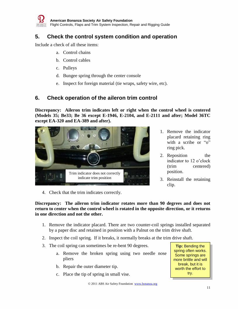
6. Check operation of the aileron trim control Discrepancy: Aileron trim indicates left or right when the control wheel is centered
(Models 35; Be33; Be 36 except E-1946, E-2104, and E-2111 and after; Model 36TC
except EA-320 and EA-389 and after).
1. Remove the indicator
placard retaining ring
with a scribe or “o”
ring pick.
2. Reposition the
indicator to 12 o’clock
(trim centered)
position.
3. Reinstall the retaining
clip.
4. Check that the trim indicates correctly.
Discrepancy: The aileron trim indicator rotates more than 90 degrees and does not
return to center when the control wheel is rotated in the opposite direction, or it returns
in one direction and not the other.
1. Remove the indicator placard. There are two counter-coil springs installed separated
by a paper disc and retained in position with a Palnut on the trim drive shaft.
2. Inspect the coil spring. If it breaks, it normally breaks at the trim drive shaft.
3. The coil spring can sometimes be re-bent 90 degrees.
a. Remove the broken spring using two needle nose
pliers
b. Repair the outer diameter tip.
c. Place the tip of spring in small vise.
Trim indicator does not correctly
indicate trim position
© 2011 ABS Air Safety Foundation www.bonanza.org
12
American Bonanza Society Air Safety Foundation
Flight Controls, Flaps and Trim System Inspection, Repair and Rigging Guide
Tip: If the center of the coil is broken use the
same procedure to bend the coil wire, allowing it to cool normally. It’s worth trying to save the spring,
because it’s a hard-to-find item.
Tip: You can make your own shims from stiff paper.
Bone paper can be found in art supply
stores.
Tip: Avoid tool marks by wrapping the pliers jaws with
duct tape.
Tip: To avoid damaging very tight forward and aft clutch body halves, wrap a single layer of masking tape around each half. Install a screw-type hose clamp on each half, with the clamp
bodies offset slightly to allow a screwdriver tip to fit horizontally between them. Move the screwdriver handle in a right arc to
loosen the clutch body halves.
d. Heat the coil until it is red, almost yellow-hot.
e. Bend the wire a sharp 90 degrees.
f. Allow the coil to cool normally.
g. File the pointed tip on bent tab of coil.
4. If the coil spring is in good shape, inspect the counter-rotating inner spring. If the
inner spring is damaged, repair it using the same procedure, or replace the inner
spring.
Discrepancy: The aileron trimmer will not hold position (it springs back) when turned
to the left or right to hold wings level.
1. When this occurs the trimmer normally needs additional friction. Friction can be
increased by adding additional paper shims between the parting halves of the
trimmer.
a. Hold the trim body nut firmly (the forward half) with
hand or cannon plug pliers.
b. Break the nut torque.
i. Firmly grasp the clutch section aft half.
ii. Turn the clutch clockwise (it has left-hand threads) until the clutch
body torque breaks.
iii. Rotate the body nut counterclockwise to free the clutch from the
assembly.
c. Install additional shim paper on the clutch shaft. Shims go around the shaft
and fill the area inside the trim knob.
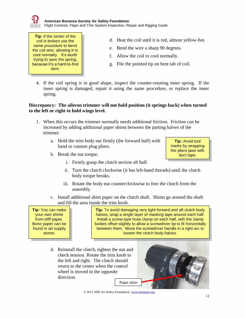
d. Reinstall the clutch, tighten the nut and
check tension. Rotate the trim knob to
the left and right. The clutch should
return to the center when the control
wheel is moved in the opposite
direction.
Paper shim
© 2011 ABS Air Safety Foundation www.bonanza.org
13
American Bonanza Society Air Safety Foundation
Flight Controls, Flaps and Trim System Inspection, Repair and Rigging Guide
Caution: The first sentence of
the Beech Shop manual instruction on section 3 page 61 paragraph b. is incorrect. You need to wrap cables a full turn in opposite directions. The rest of the instructions are correct.
Tip: The work takes patience. You may
consider starting with two cables. Often the first cable
is sacrificed.
7. Check the elevator/ruddervator trim indicator and wheel
Check the:
1. Trim wheel for drag.
2. Indicator for proper position indication.
a. Set the cockpit trim indicator to zero.
b. Note that the trim tabs are set neutral (the flat surface of the tab is flush with
the control surface).
3. Cable condition.
4. Trim stops.
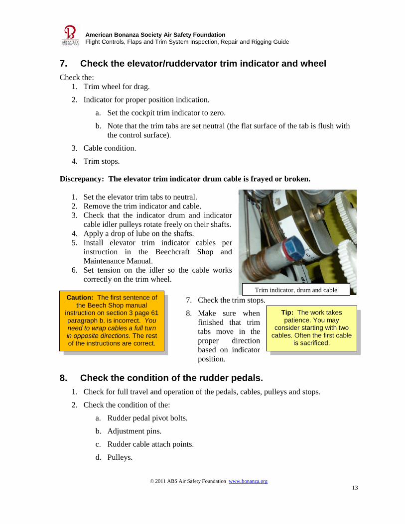
Discrepancy: The elevator trim indicator drum cable is frayed or broken.
1. Set the elevator trim tabs to neutral.
2. Remove the trim indicator and cable.
3. Check that the indicator drum and indicator
cable idler pulleys rotate freely on their shafts.
4. Apply a drop of lube on the shafts.
5. Install elevator trim indicator cables per
instruction in the Beechcraft Shop and
Maintenance Manual.
6. Set tension on the idler so the cable works
correctly on the trim wheel.
7. Check the trim stops.
8. Make sure when
finished that trim
tabs move in the
proper direction
based on indicator
position.
8. Check the condition of the rudder pedals.
1. Check for full travel and operation of the pedals, cables, pulleys and stops.
2. Check the condition of the:
a. Rudder pedal pivot bolts.
b. Adjustment pins.
c. Rudder cable attach points.
d. Pulleys.
Trim indicator, drum and cable

© 2011 ABS Air Safety Foundation www.bonanza.org
14
American Bonanza Society Air Safety Foundation
Flight Controls, Flaps and Trim System Inspection, Repair and Rigging Guide
Tip: Worn or elongated pivot
holes are usually the result of using the brakes to steer the
airplane.
Tip: There may not be enough material to safely complete a
repair to prevent continuing wear.
Because the arms are made of
magnesium, no weld repairs of holes are
possible.
Tip: If the bolt hole wear is too large, the pilot rudder pedal arms can be relocated to the copilot side and the copilot pedals can be used to replace the worn arms (often there are no pedals on the copilot-side
arms). The process takes a good amount of labor and is usually done only if parts are not available.
Discrepancy: Wear or elongation of rudder pedal pivot bolt holes.
1. Remove the rudder pedal from rudder pedal arm.
2. Remove the bolt for the master cylinder, and the two pivot
bolts.
3. Check for wear on the rudder pedal arm pivot holes.
4. Check the edge distance from the arm to the inside of the bolt hole.
5. To replace or relocate pedal arms from the copilot side to
the pilot side:
a. Place the aircraft on jacks.
b. Note the left rudder pedal torque tube has
a steering bell crank and aileron/rudder
bungee bell crank on the inboard end. The
right torque tube has a nose landing gear
retract rod idler arm attached on the
inboard end.
c. Remove the center console cover and
floorboard for easier access to the torque tube ends.
d. Remove the bolts from the torque tube. There is one bolt on the inboard side
of each rudder pedal.
e. Slide the torque tube inboard to remove the rudder pedal arms.
f. Use the same procedure for the pilot side, except the bolt must be removed
from the steering
bell crank. Move
the torque tube
inboard and remove
the rudder pedal
arms.
g. Install replacement
arms or relocate the
arms on the torque
tube.
h. Reinstall the bolts.
Idler arm
Idler arms and torque tubes
© 2011 ABS Air Safety Foundation www.bonanza.org
15
American Bonanza Society Air Safety Foundation
Flight Controls, Flaps and Trim System Inspection, Repair and Rigging Guide
Tip: Frozen rudder adjustment pins are usually the result of
corrosion.
Tip: Remove corrosion with a small round wire brush, or 220
wet/dry sandpaper taped around a small wooden dowel. Use a cotton
swap to apply Alodine and Magnadyne, then (after completely
drying) zinc chromate.
Tip: Latch pins can often be moved after a generous
soaking with penetrating oil. Use parallel-jaw pliers with smooth jaws, without teeth, to apply left-right pressure
to the adjustment pins.
Caution: Make flap UP and DOWN adjustments with a suitable power
supply connected to the aircraft that provides the approximate voltage
output of an operating alternator or generator. Flap UP limit adjustments
made with battery voltage only will most likely be too tight when the flaps
are retracted with an alternator or generator on line.
i. Reinstall the pedals
j. Lubricate the pivot bolts.
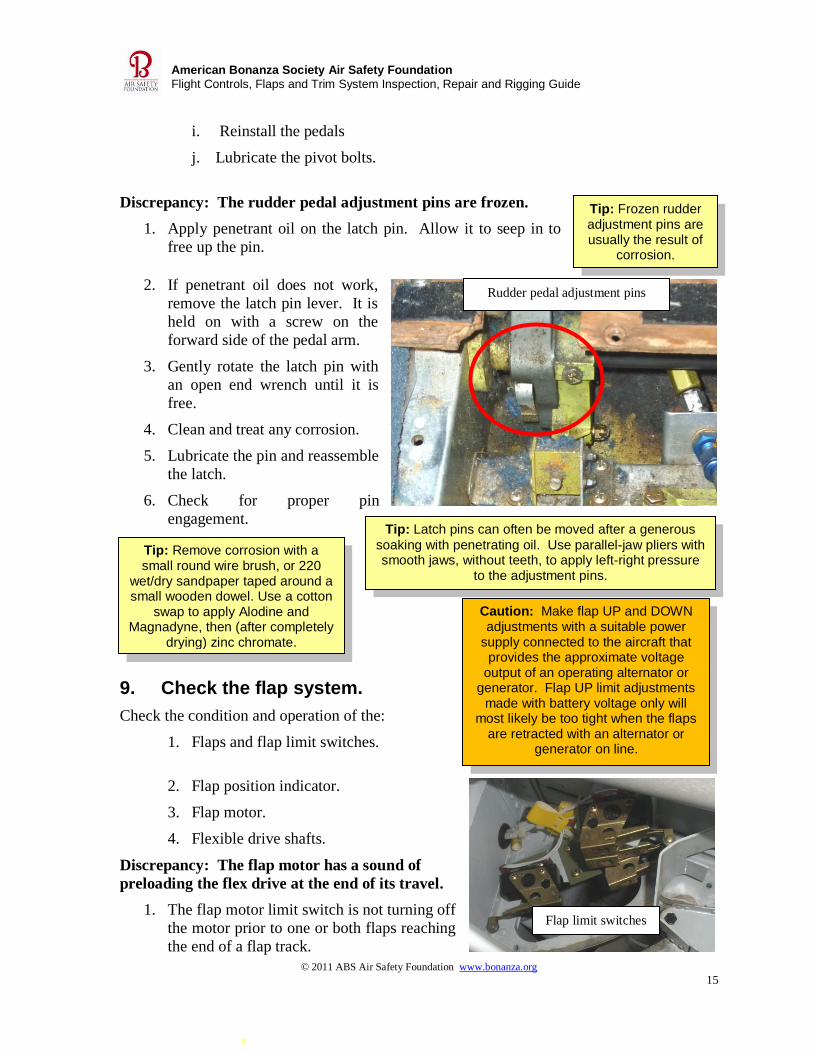
Discrepancy: The rudder pedal adjustment pins are frozen.
1. Apply penetrant oil on the latch pin. Allow it to seep in to
free up the pin.
2. If penetrant oil does not work,
remove the latch pin lever. It is
held on with a screw on the
forward side of the pedal arm.
3. Gently rotate the latch pin with
an open end wrench until it is
free.
4. Clean and treat any corrosion.
5. Lubricate the pin and reassemble
the latch.
6. Check for proper pin
engagement.
9. Check the flap system.
Check the condition and operation of the:
1. Flaps and flap limit switches.
2. Flap position indicator.
3. Flap motor.
4. Flexible drive shafts.
Discrepancy: The flap motor has a sound of
preloading the flex drive at the end of its travel.
1. The flap motor limit switch is not turning off
the motor prior to one or both flaps reaching
the end of a flap track.
Rudder pedal adjustment pins
Flap limit switches
© 2011 ABS Air Safety Foundation www.bonanza.org
16
American Bonanza Society Air Safety Foundation
Flight Controls, Flaps and Trim System Inspection, Repair and Rigging Guide
Tip: Flap limit switches are in the left flap well. The
left flap is the master flap, and the right
flap is a slave.
Tip: Use rope caulk or play dough in the
slot to measure forward roller travel. The aft roller can be
visually checked.
Tip: A connection on the flap indicator circuit board may
also be causing the problem. Circuit
board problems may be intermittent depending on temperature.
Tip: Check to see that
the flexible drive shaft is centered in flex drive
housing.
2. Determine which flap is over traveling. Flap rollers should
stop 1/16” – 1/32” before the end
of the flap track slot.
3. If the left flap is hitting the end of
the track slot, adjust the limit
switches in left flap well to bring
flap travel within limits.
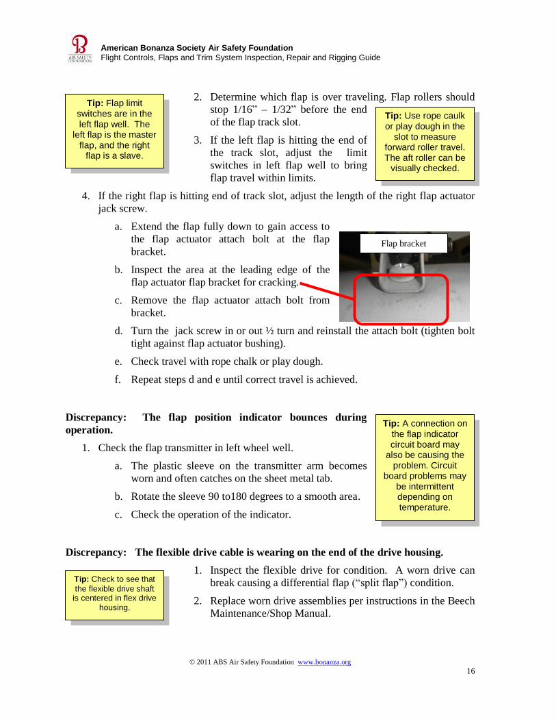
4. If the right flap is hitting end of track slot, adjust the length of the right flap actuator
jack screw.
a. Extend the flap fully down to gain access to
the flap actuator attach bolt at the flap
bracket.
b. Inspect the area at the leading edge of the
flap actuator flap bracket for cracking.
c. Remove the flap actuator attach bolt from
bracket.
d. Turn the jack screw in or out ½ turn and reinstall the attach bolt (tighten bolt
tight against flap actuator bushing).
e. Check travel with rope chalk or play dough.
f. Repeat steps d and e until correct travel is achieved.
Discrepancy: The flap position indicator bounces during
operation.
1. Check the flap transmitter in left wheel well.
a. The plastic sleeve on the transmitter arm becomes
worn and often catches on the sheet metal tab.
b. Rotate the sleeve 90 to180 degrees to a smooth area.
c. Check the operation of the indicator.
Discrepancy: The flexible drive cable is wearing on the end of the drive housing.
1. Inspect the flexible drive for condition. A worn drive can
break causing a differential flap (“split flap”) condition.
2. Replace worn drive assemblies per instructions in the Beech
Maintenance/Shop Manual.
Flap bracket

© 2011 ABS Air Safety Foundation www.bonanza.org
17
American Bonanza Society Air Safety Foundation
Flight Controls, Flaps and Trim System Inspection, Repair and Rigging Guide
Tip: Flap hunting normally happens in flight with an air load, but is sometimes seen when selecting the approach position on the ground. Periodically check rollers for freedom to roll, and
frequently lubricate the rollers with LPS 1 to prevent bending the switch arms.
Discrepancy: Flap transit speed is irregular, or the flaps encounter resistance while in
transit.
1. Remove, lubricate and reinstall the flexible drive cables per the Beechcraft
Maintenance/Shop Manual.
2. Check the operation of the flaps.
Discrepancy: The flaps hunt up and down (“flap bounce”) in the approach position
(airplanes with approach-preselect flaps).
1. Check that the switch activator arms for the 11/14-
and 12/16- degree position switches (the center two
switches banked together) are not bent.
2. Straighten switch actuator or adjust switches for a 2
degree separation of flap travel as necessary.
3. Check that the rollers on the end of the switch arms
are free to roll.
4. Lubricate the switches rollers with LPS 1.
Discrepancy: There is crack damage to the nose rib assembly for the flap actuator
attachment bracket.
Address cracks in accordance with Hawker Beechcraft Safety Communiqué 313 rev. 1.
Illustrations from Safety Communiqué 313 rev. 1
Flap limit switch
rollers (2 or 4
depending on model)
© 2011 ABS Air Safety Foundation www.bonanza.org
18
American Bonanza Society Air Safety Foundation
Flight Controls, Flaps and Trim System Inspection, Repair and Rigging Guide
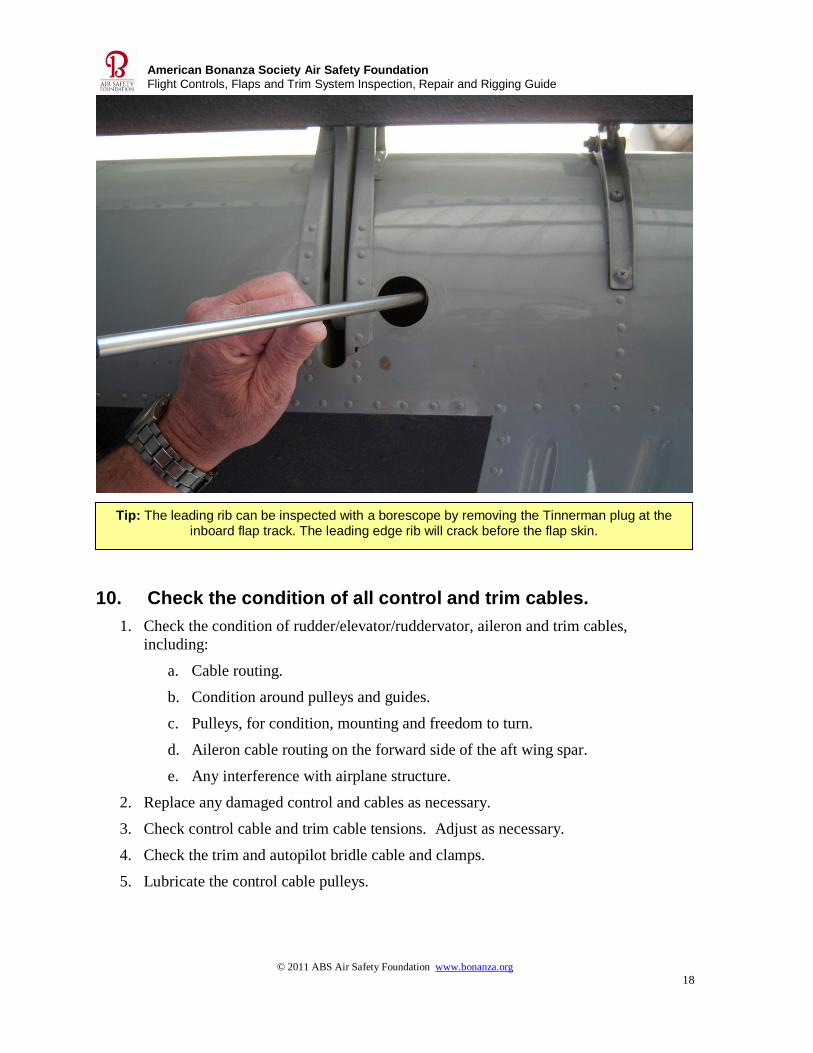
Tip: The leading rib can be inspected with a borescope by removing the Tinnerman plug at the inboard flap track. The leading edge rib will crack before the flap skin.
10. Check the condition of all control and trim cables.
1. Check the condition of rudder/elevator/ruddervator, aileron and trim cables,
including:
a. Cable routing.
b. Condition around pulleys and guides.
c. Pulleys, for condition, mounting and freedom to turn.
d. Aileron cable routing on the forward side of the aft wing spar.
e. Any interference with airplane structure.
2. Replace any damaged control and cables as necessary.
3. Check control cable and trim cable tensions. Adjust as necessary.
4. Check the trim and autopilot bridle cable and clamps.
5. Lubricate the control cable pulleys.
© 2011 ABS Air Safety Foundation www.bonanza.org
19
American Bonanza Society Air Safety Foundation
Flight Controls, Flaps and Trim System Inspection, Repair and Rigging Guide
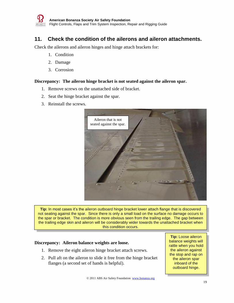
Tip: In most cases it’s the aileron outboard hinge bracket lower attach flange that is discovered not seating against the spar. Since there is only a small load on the surface no damage occurs to the spar or bracket. The condition is more obvious seen from the trailing edge. The gap between the trailing edge skin and aileron will be considerably wider towards the unattached bracket when
this condition occurs.
Tip: Loose aileron balance weights will rattle when you hold the aileron against the stop and rap on
the aileron spar inboard of the
outboard hinge.
11. Check the condition of the ailerons and aileron attachments.
Check the ailerons and aileron hinges and hinge attach brackets for:
1. Condition
2. Damage
3. Corrosion
Discrepancy: The aileron hinge bracket is not seated against the aileron spar.
1. Remove screws on the unattached side of bracket.
2. Seat the hinge bracket against the spar.
3. Reinstall the screws.
Discrepancy: Aileron balance weights are loose.
1. Remove the eight aileron hinge bracket attach screws.
2. Pull aft on the aileron to slide it free from the hinge bracket
flanges (a second set of hands is helpful).
Aileron that is not
seated against the spar.
© 2011 ABS Air Safety Foundation www.bonanza.org
20
American Bonanza Society Air Safety Foundation
Flight Controls, Flaps and Trim System Inspection, Repair and Rigging Guide
Tip: Extend the flaps fully down for better clearance while you remove and reinstall
the aileron.
Tip: Extend the flaps full down for better clearance
during removal and installation of
aileron.
3. Disconnect the static discharge bonding cables.
4. Re-squeeze the existing rivets on any loose balance
weight first, to try to tighten the weight down.
5. Check if the weight is now tight. If not, replace the
rivet(s).
6. To install the aileron:
a. Attach the static discharge bonding cables.
b. Place the aileron in position on the hinge brackets.
c. Check that the hinge bracket is fully seated against the spar.
d. Install all eight upper and lower hinge attach screws.
Discrepancy: The aileron push-pull rod is binding, and is not rotating side-to-side.
1. Lubricate the rod ends.
2. Check rod end alignment:
a. Hold the aileron trailing edge down.
b. Loosen the rod end jamb nut attached to the aileron bell crank or aileron hinge
bracket.
c. Rotate both rod ends to full travel in the direction the lose jamb nut tightens.
d. Tighten the jamb nut.
e. Check that the push-pull rod rotates freely side to side and does not bind.
Discrepancy: The aileron aft push-pull rod end is worn, giving excessive vertical
movement on the aileron trailing edge.
1. Remove all eight hinge bracket attach screws.
2. Pull aft on the aileron to slide the control free from hinge
bracket flanges (a second set of hands is helpful).
3. Support the aileron-to-hinge brackets with safety wire. Do not
trust the static discharge bonding cables to support the aileron.
4. Remove the aft rod end attach bolt from the hinge bracket.
5. Before removing the rod end, measure the distance along the centerline of the rod end
from the ball to the end of the push-pull tube.
6. Adjust the new rod end to the same length as the one removed.
7. Attach the rod end to the hinge bracket before tightening the jamb nut.
8. Rotate the rod in the direction of tightening jamb nut.
© 2011 ABS Air Safety Foundation www.bonanza.org
21
American Bonanza Society Air Safety Foundation
Flight Controls, Flaps and Trim System Inspection, Repair and Rigging Guide
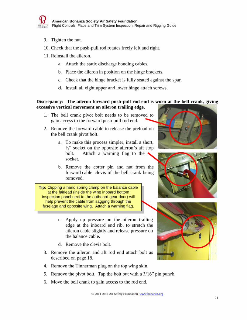
Tip: Clipping a hand spring clamp on the balance cable at the fairlead (inside the wing inboard bottom
inspection panel next to the outboard gear door) will help prevent the cable from sagging through the
fuselage and opposite wing. Attach a warning flag.
9. Tighten the nut.
10. Check that the push-pull rod rotates freely left and right.
11. Reinstall the aileron.
a. Attach the static discharge bonding cables.
b. Place the aileron in position on the hinge brackets.
c. Check that the hinge bracket is fully seated against the spar.
d. Install all eight upper and lower hinge attach screws.
Discrepancy: The aileron forward push-pull rod end is worn at the bell crank, giving
excessive vertical movement on aileron trailing edge.
1. The bell crank pivot bolt needs to be removed to
gain access to the forward push-pull rod end.
2. Remove the forward cable to release the preload on
the bell crank pivot bolt.
a. To make this process simpler, install a short,
½” socket on the opposite aileron’s aft stop
bolt. Attach a warning flag to the
socket.
b. Remove the cotter pin and nut from the
forward cable clevis of the bell crank being
removed.
c. Apply up pressure on the aileron trailing
edge at the inboard end rib, to stretch the
aileron cable slightly and release pressure on
the balance cable.
d. Remove the clevis bolt.
3. Remove the aileron and aft rod end attach bolt as
described on page 18.
4. Remove the Tinnerman plug on the top wing skin.
5. Remove the pivot bolt. Tap the bolt out with a 3/16” pin punch.
6. Move the bell crank to gain access to the rod end.
© 2011 ABS Air Safety Foundation www.bonanza.org
22
American Bonanza Society Air Safety Foundation
Flight Controls, Flaps and Trim System Inspection, Repair and Rigging Guide
Tip: Address corrosion as soon as it is discovered.
Minor corrosion can often be treated, and prevents the need to replace the
control skin.
7. Remove the attach bolt.
8. Measure the distance along the centerline of the rod end from the ball to the end of
the push-pull tube.
9. Remove the old rod end, and attach the new rod end to the same length as the one
removed.
10. Reinstall the push-pull rod, attach bolt and cotter pin.
11. Reinstall the bell crank.
12. Tighten the pivot bolt securely and attach a cotter pin.
13. Reattach the push-pull rod attach bolt to the inboard aileron hinge bracket.
14. Tighten the forward push-pull rod end jamb nut.
15. Check that the push-pull rod rotates freely edge to edge.
16. Reinstall the aileron.
17. Apply up pressure on the aileron to stretch the aileron cable.
18. Install the clevis bolt, install the nut, and safety with a cotter pin.
19. Remove the ½ inch socket and warning flag from the aileron bell crank stop.
20. Remove the hand clamp and warning flag.
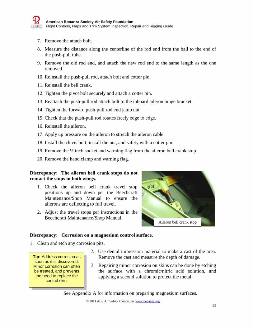
Discrepancy: The aileron bell crank stops do not
contact the stops in both wings.
1. Check the aileron bell crank travel stop
positions up and down per the Beechcraft
Maintenance/Shop Manual to ensure the
ailerons are deflecting to full travel.
2. Adjust the travel stops per instructions in the
Beechcraft Maintenance/Shop Manual.
Discrepancy: Corrosion on a magnesium control surface.
1. Clean and etch any corrosion pits.
2. Use dental impression material to make a cast of the area.
Remove the cast and measure the depth of damage.
3. Repairing minor corrosion on skins can be done by etching
the surface with a chromic/nitric acid solution, and
applying a second solution to protect the metal.
See Appendix A for information on preparing magnesium surfaces.
Aileron bell crank stop
© 2011 ABS Air Safety Foundation www.bonanza.org
23
American Bonanza Society Air Safety Foundation
Flight Controls, Flaps and Trim System Inspection, Repair and Rigging Guide
Tip: Fairleads are used to redirect a cable slightly for alignment, and to
prevent wear interference with
other components.
Tip: Corrosion on a control surface normally requires replacement of
skin. The maximum allowable corrosion depth
limit is 10% of the skin thickness.
4. Remove, repaint and balance the control surface.
5. Corrosion beyond allowable limits requires reskinning or
replacing the control surface.
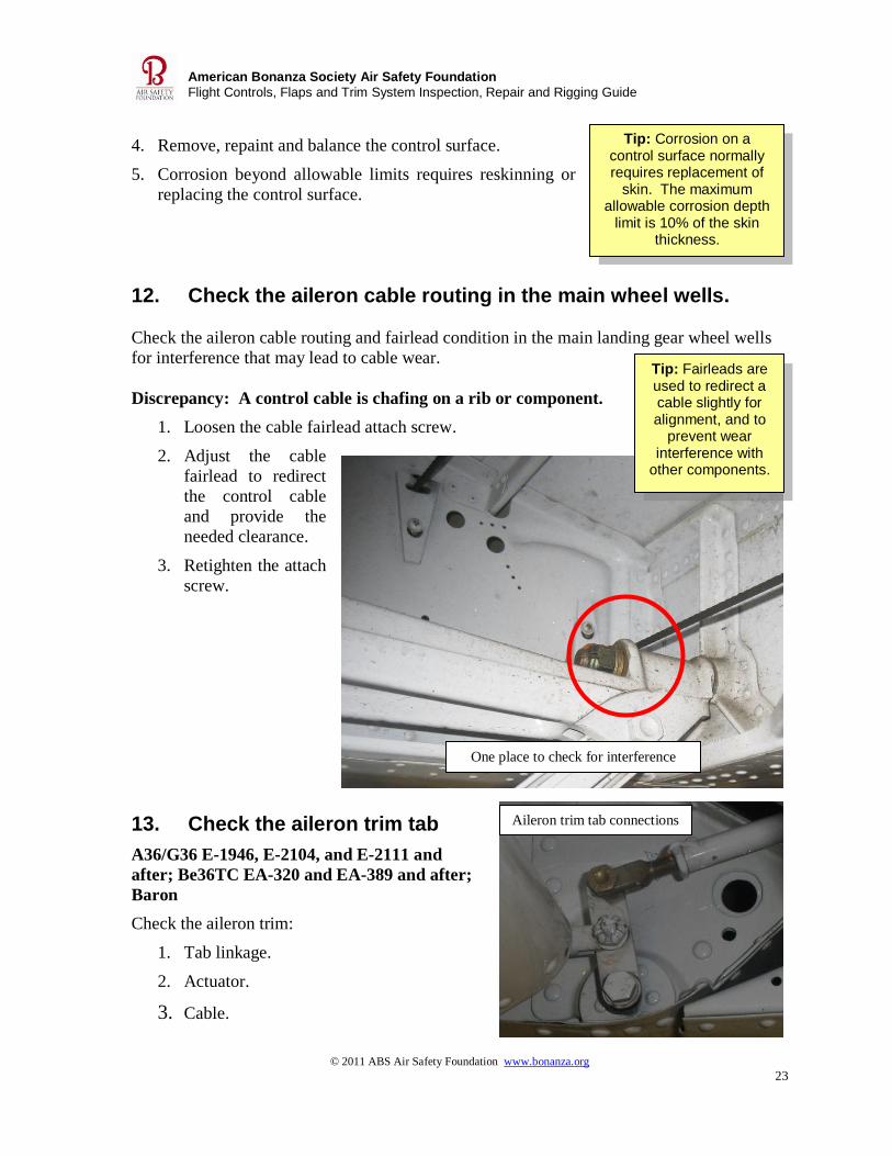
12. Check the aileron cable routing in the main wheel wells.
Check the aileron cable routing and fairlead condition in the main landing gear wheel wells
for interference that may lead to cable wear.
Discrepancy: A control cable is chafing on a rib or component.
1. Loosen the cable fairlead attach screw.
2. Adjust the cable
fairlead to redirect
the control cable
and provide the
needed clearance.
3. Retighten the attach
screw.
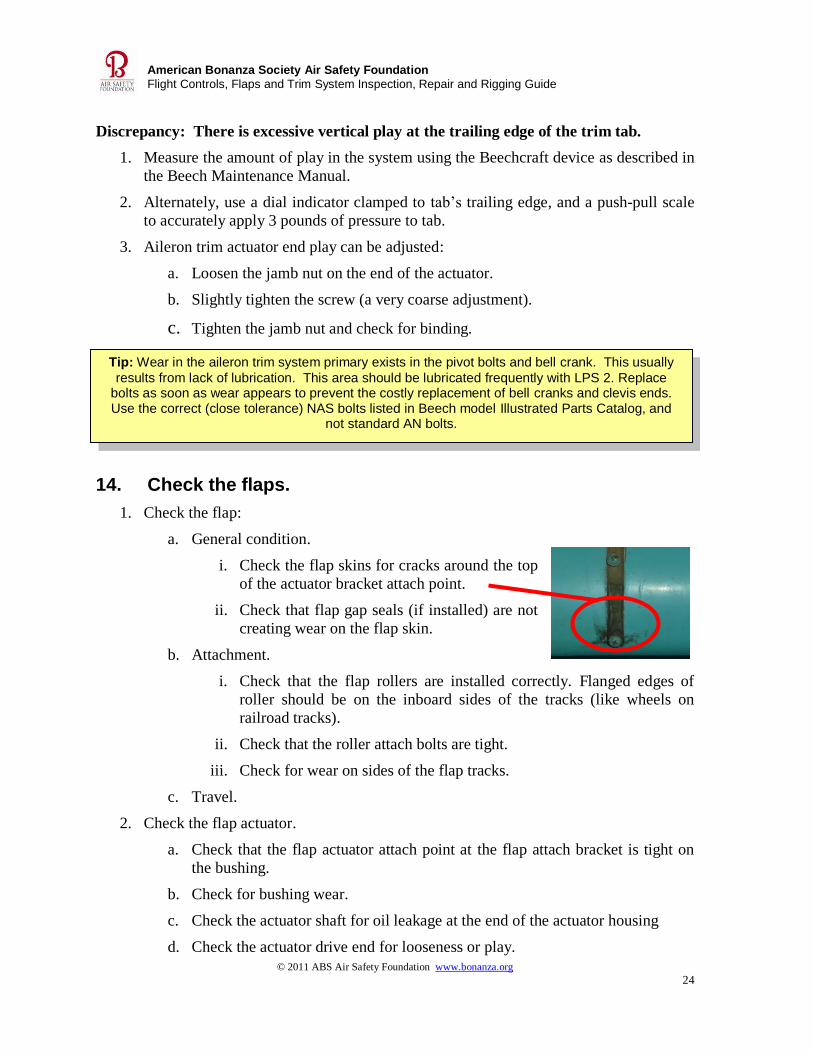
13. Check the aileron trim tab
A36/G36 E-1946, E-2104, and E-2111 and
after; Be36TC EA-320 and EA-389 and after;
Baron
Check the aileron trim:
1. Tab linkage.
2. Actuator.
3. Cable.
One place to check for interference
Aileron trim tab connections
© 2011 ABS Air Safety Foundation www.bonanza.org
24
American Bonanza Society Air Safety Foundation
Flight Controls, Flaps and Trim System Inspection, Repair and Rigging Guide
Tip: Wear in the aileron trim system primary exists in the pivot bolts and bell crank. This usually
results from lack of lubrication. This area should be lubricated frequently with LPS 2. Replace bolts as soon as wear appears to prevent the costly replacement of bell cranks and clevis ends. Use the correct (close tolerance) NAS bolts listed in Beech model Illustrated Parts Catalog, and
not standard AN bolts.
Discrepancy: There is excessive vertical play at the trailing edge of the trim tab.
1. Measure the amount of play in the system using the Beechcraft device as described in
the Beech Maintenance Manual.
2. Alternately, use a dial indicator clamped to tab’s trailing edge, and a push-pull scale
to accurately apply 3 pounds of pressure to tab.
3. Aileron trim actuator end play can be adjusted:
a. Loosen the jamb nut on the end of the actuator.
b. Slightly tighten the screw (a very coarse adjustment).
c. Tighten the jamb nut and check for binding.
14. Check the flaps.
1. Check the flap:
a. General condition.
i. Check the flap skins for cracks around the top
of the actuator bracket attach point.
ii. Check that flap gap seals (if installed) are not
creating wear on the flap skin.
b. Attachment.
i. Check that the flap rollers are installed correctly. Flanged edges of
roller should be on the inboard sides of the tracks (like wheels on
railroad tracks).
ii. Check that the roller attach bolts are tight.
iii. Check for wear on sides of the flap tracks.
c. Travel.
2. Check the flap actuator.
a. Check that the flap actuator attach point at the flap attach bracket is tight on
the bushing.
b. Check for bushing wear.
c. Check the actuator shaft for oil leakage at the end of the actuator housing
d. Check the actuator drive end for looseness or play.
© 2011 ABS Air Safety Foundation www.bonanza.org
25
American Bonanza Society Air Safety Foundation
Flight Controls, Flaps and Trim System Inspection, Repair and Rigging Guide
Tip: Keep flap actuator drive shafts clean and free of oil and dirt build up. Shafts should be dry and not lubricated. Oil and dirt will cause actuators to leak. The best time to inspect flap drive
shafts is during the landing gear inspection
Tip: The flap actuator unit must
be removed through the wheel
well if it is to be disassembled and
resealed.
Tip: Shims may be installed in the actuator to remove the endplay between the actuator screw and housing. There are three different thicknesses of shims available. If the excessive wear is in
the screw and piston assembly, the worn item must be replaced.
3. Check the flap position transmitter in the left wheel well for attachment and
condition.
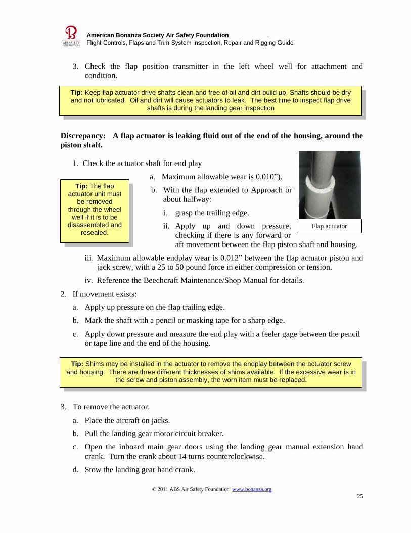
Discrepancy: A flap actuator is leaking fluid out of the end of the housing, around the
piston shaft.
1. Check the actuator shaft for end play
a. Maximum allowable wear is 0.010”).
b. With the flap extended to Approach or
about halfway:
i. grasp the trailing edge.
ii. Apply up and down pressure,
checking if there is any forward or
aft movement between the flap piston shaft and housing.
iii. Maximum allowable endplay wear is 0.012” between the flap actuator piston and
jack screw, with a 25 to 50 pound force in either compression or tension.
iv. Reference the Beechcraft Maintenance/Shop Manual for details.
2. If movement exists:
a. Apply up pressure on the flap trailing edge.
b. Mark the shaft with a pencil or masking tape for a sharp edge.
c. Apply down pressure and measure the end play with a feeler gage between the pencil
or tape line and the end of the housing.
3. To remove the actuator:
a. Place the aircraft on jacks.
b. Pull the landing gear motor circuit breaker.
c. Open the inboard main gear doors using the landing gear manual extension hand
crank. Turn the crank about 14 turns counterclockwise.
d. Stow the landing gear hand crank.
Flap actuator
© 2011 ABS Air Safety Foundation www.bonanza.org
26
American Bonanza Society Air Safety Foundation
Flight Controls, Flaps and Trim System Inspection, Repair and Rigging Guide
Tip: Some fluid may leak out of the
vent hole on the first couple of cycles. This is
normal.
Tip: Cracks in the flap skin along the leading edge attach bracket also indicate a crack and failure
of the leading edge rib to which the bracket is attached. The flap skin and leading edge rib may be replaced, or the leading edge rib may be replaced and the skin repaired without replacing the skin.
Tip: A #2 pin router in a
Dremel tool at high speed
works well to cut the leading edge
skin.
e. Extend the flaps fully down.
f. Pull the flap motor circuit breaker.
g. Remove the actuator-to-flap attach bolt.
h. Remove the flap actuator housing pivot bolts in the wheel well.
i. Remove the flex drive snap ring.
j. Pull the flex drive free of actuator.
k. Remove the actuator from the wing.
l. Measure the length the actuator shaft extends out of the housing.
m. Service and reassemble the actuator per instructions in the
Beechcraft Maintenance/Shop Manual.
n. Reinstall the flap actuator, with the vent hole up, to the same
distance of extension measured in step l.
o. Check flap travel.
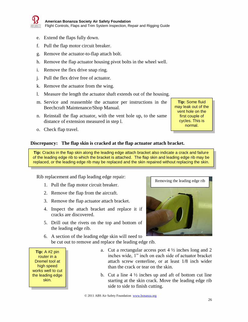
Discrepancy: The flap skin is cracked at the flap actuator attach bracket.
Rib replacement and flap leading edge repair:
1. Pull the flap motor circuit breaker.
2. Remove the flap from the aircraft.
3. Remove the flap actuator attach bracket.
4. Inspect the attach bracket and replace it if
cracks are discovered.
5. Drill out the rivets on the top and bottom of
the leading edge rib.
6. A section of the leading edge skin will need to
be cut out to remove and replace the leading edge rib.
a. Cut a rectangular access port 4 ½ inches long and 2
inches wide, 1” inch on each side of actuator bracket
attach screw centerline, or at least 1/8 inch wider
than the crack or tear on the skin.
b. Cut a line 4 ½ inches up and aft of bottom cut line
starting at the skin crack. Move the leading edge rib
side to side to finish cutting.
Removing the leading edge rib
© 2011 ABS Air Safety Foundation www.bonanza.org
27
American Bonanza Society Air Safety Foundation
Flight Controls, Flaps and Trim System Inspection, Repair and Rigging Guide
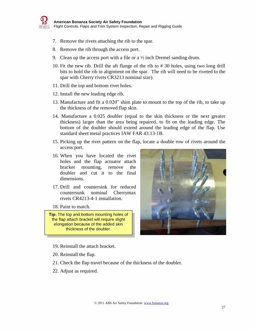
Tip: The top and bottom mounting holes of
the flap attach bracket will require slight elongation because of the added skin
thickness of the doubler.
7. Remove the rivets attaching the rib to the spar.
8. Remove the rib through the access port.
9. Clean up the access port with a file or a ½ inch Dremel sanding drum.
10. Fit the new rib. Drill the aft flange of the rib to # 30 holes, using two long drill
bits to hold the rib in alignment on the spar. The rib will need to be riveted to the
spar with Cherry rivets CR3213 nominal size).
11. Drill the top and bottom rivet holes.
12. Install the new leading edge rib.
13. Manufacture and fit a 0.020” shim plate to mount to the top of the rib, to take up
the thickness of the removed flap skin.
14. Manufacture a 0.025 doubler (equal to the skin thickness or the next greater
thickness) larger than the area being repaired, to fit on the leading edge. The
bottom of the doubler should extend around the leading edge of the flap. Use
standard sheet metal practices IAW FAR 43.13-1B.
15. Picking up the rivet pattern on the flap, locate a double row of rivets around the
access port.
16. When you have located the rivet
holes and the flap actuator attach
bracket mounting, remove the
doubler and cut it to the final
dimensions.
17. Drill and countersink for reduced
countersunk nominal Cherrymax
rivets CR4213-4-1 installation.
18. Paint to match.
19. Reinstall the attach bracket.
20. Reinstall the flap.
21. Check the flap travel because of the thickness of the doubler.
22. Adjust as required.
© 2011 ABS Air Safety Foundation www.bonanza.org
28
American Bonanza Society Air Safety Foundation
Flight Controls, Flaps and Trim System Inspection, Repair and Rigging Guide
Tip: Because of restricted access, bucking a solid rivet is very difficult. We suggest installing a washer with a lock washer under the flap bumper
jamb nut.
Tip: Bonanzas serial number D-1 through D-7750 had a rubber pad cemented to the flap track instead of the later flap bumper. To upgrade to the later configuration, see Beechcraft Service
Letter No. 65-40.
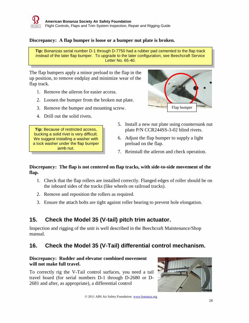
Discrepancy: A flap bumper is loose or a bumper nut plate is broken.
The flap bumpers apply a minor preload to the flap in the
up position, to remove endplay and minimize wear of the
flap track.
1. Remove the aileron for easier access.
2. Loosen the bumper from the broken nut plate.
3. Remove the bumper and mounting screw.
4. Drill out the solid rivets.
5. Install a new nut plate using countersunk nut
plate P/N CCR244SS-3-02 blind rivets.
6. Adjust the flap bumper to supply a light
preload on the flap.
7. Reinstall the aileron and check operation.
Discrepancy: The flap is not centered on flap tracks, with side-to-side movement of the
flap.
1. Check that the flap rollers are installed correctly. Flanged edges of roller should be on
the inboard sides of the tracks (like wheels on railroad tracks).
2. Remove and reposition the rollers as required.
3. Ensure the attach bolts are tight against roller bearing to prevent hole elongation.
15. Check the Model 35 (V-tail) pitch trim actuator.
Inspection and rigging of the unit is well described in the Beechcraft Maintenance/Shop
manual.
16. Check the Model 35 (V-Tail) differential control mechanism. Discrepancy: Rudder and elevator combined movement
will not make full travel.
To correctly rig the V-Tail control surfaces, you need a tail
travel board (for serial numbers D-1 through D-2680 or D-
2681 and after, as appropriate), a differential control
Flap bumper
© 2011 ABS Air Safety Foundation www.bonanza.org
29
American Bonanza Society Air Safety Foundation
Flight Controls, Flaps and Trim System Inspection, Repair and Rigging Guide
Tip: To measure the length of the short cable between the reduction bell crank and the elevator control arm on the differential
mechanism, make a measuring cable out of 20 or 22 gauge electrical wire and two 10-32 wire terminals. Crimp the terminals on the wire so the centerline of the terminal ends is exactly 23 5/8 inches long. No
threads should be visible outside the barrel after adjustment. Safety the turnbuckle.
No further adjustment of this cable is required.
mechanism jig, a rudder rig pin (applicable to the airplane’s serial number), and a control
column stop (4.5 inches, or 4.75 inches for D-10359 to D-10403). ABS rents some of these
items if they are not available locally.
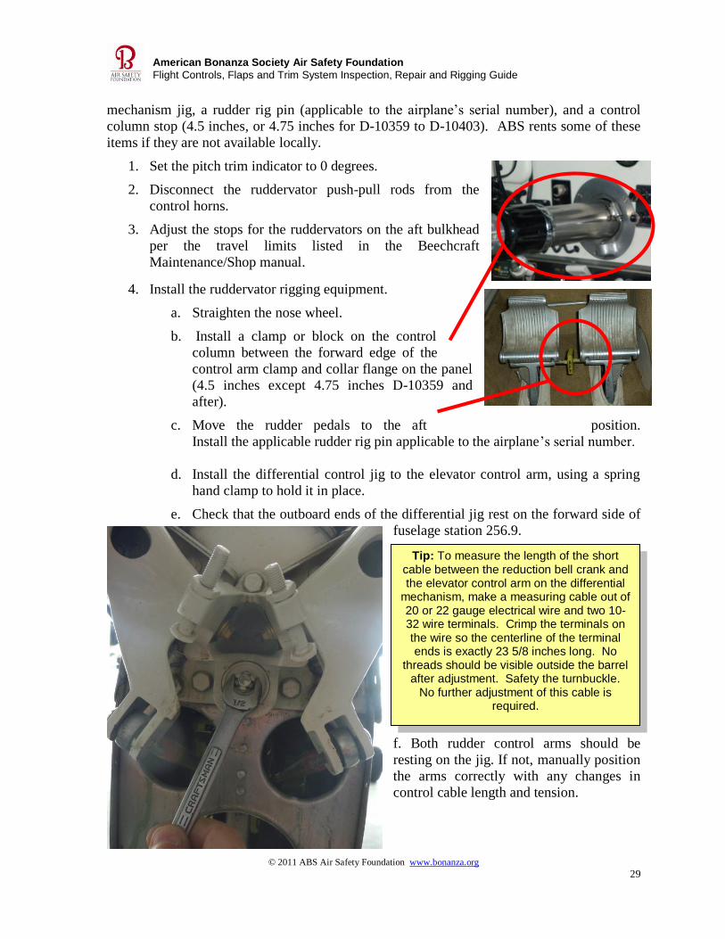
1. Set the pitch trim indicator to 0 degrees.
2. Disconnect the ruddervator push-pull rods from the
control horns.
3. Adjust the stops for the ruddervators on the aft bulkhead
per the travel limits listed in the Beechcraft
Maintenance/Shop manual.
4. Install the ruddervator rigging equipment.
a. Straighten the nose wheel.
b. Install a clamp or block on the control
column between the forward edge of the
control arm clamp and collar flange on the panel
(4.5 inches except 4.75 inches D-10359 and
after).
c. Move the rudder pedals to the aft position.
Install the applicable rudder rig pin applicable to the airplane’s serial number.
d. Install the differential control jig to the elevator control arm, using a spring
hand clamp to hold it in place.
e. Check that the outboard ends of the differential jig rest on the forward side of
fuselage station 256.9.
f. Both rudder control arms should be
resting on the jig. If not, manually position
the arms correctly with any changes in
control cable length and tension.

© 2011 ABS Air Safety Foundation www.bonanza.org
30
American Bonanza Society Air Safety Foundation
Flight Controls, Flaps and Trim System Inspection, Repair and Rigging Guide
g. Check and adjust the elevator and rudder cable tensions per the serial number range in the
Beechcraft Maintenance/Shop Manual, until the differential control arms are in the
correct position.
h. The rudder balance cable may need to be adjusted on the aft bulkhead during the rigging
procedure to position the rudder arms correctly (so they are just touching the aft edge of
the differential jig).
a. Adjust the rudder cable to the tensions on the graph in the Beech
Maintenance/Shop Manual.
b. Safety the balance cable adjustment nut.
i. Check that the elevator and rudder control arms are in the neutral position (so the rudder
arms are touching the aft edge of the jig and the jig is touching the forward side of the
bulkhead). Safety the turnbuckles as required.
j. Check and adjust the ruddervator trailing edge to a 0-degree position with tail travel
boards.
k. Tighten the push-pull rod jamb nuts.
l. Check that the push-pull rod ends will rotate freely (full travel side to side).
m. Safety the control rod ends.
n. Remove rigging equipment.
o. Check that the ruddervators make full combined travel in both directions.
Discrepancy: One ruddervator push-pull rod is noticeably shorter than the other.
This discrepancy may result when the differential control mechanism is not rigged correctly,
or if the ruddervators have been rigged to neutral (0 degree position) without the use of a
differential control jig or using the control balance weight horns to align the stabilizer instead
of using a travel board.
1. In the cockpit, set the elevator trim to 0 degrees.
2. Center the airplane’s nose wheel.
3. Install a rudder rig pin applicable to the aircraft’s serial number.
4. Install a clamp or block onto the control column to hold 4.5 inch (4.75 inches for
serial numbers D-10359 to D-10403) between the forward edge of the control arm
clamp and the collar flange on the instrument panel.
5. Install the differential control jig applicable to the aircraft’s serial number. Attach the
jig to the differential control mechanism elevator control arm using a spring hand
clamp to hold the jig in place.
6. Using a tail travel board, set the control to the neutral, 0 degree position.
© 2011 ABS Air Safety Foundation www.bonanza.org
31
American Bonanza Society Air Safety Foundation
Flight Controls, Flaps and Trim System Inspection, Repair and Rigging Guide
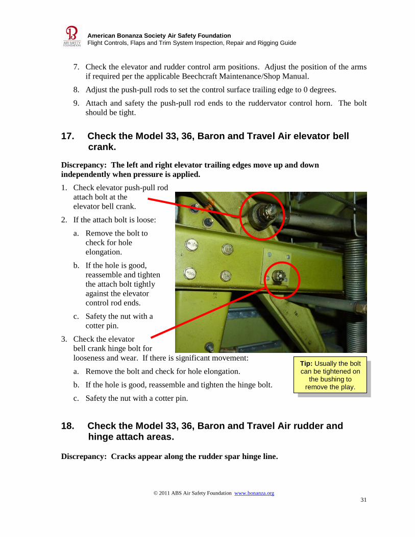
Tip: Usually the bolt can be tightened on
the bushing to remove the play.
7. Check the elevator and rudder control arm positions. Adjust the position of the arms
if required per the applicable Beechcraft Maintenance/Shop Manual.
8. Adjust the push-pull rods to set the control surface trailing edge to 0 degrees.
9. Attach and safety the push-pull rod ends to the ruddervator control horn. The bolt
should be tight.
17. Check the Model 33, 36, Baron and Travel Air elevator bell crank.
Discrepancy: The left and right elevator trailing edges move up and down
independently when pressure is applied.
1. Check elevator push-pull rod
attach bolt at the
elevator bell crank.
2. If the attach bolt is loose:
a. Remove the bolt to
check for hole
elongation.
b. If the hole is good,
reassemble and tighten
the attach bolt tightly
against the elevator
control rod ends.
c. Safety the nut with a
cotter pin.
3. Check the elevator
bell crank hinge bolt for
looseness and wear. If there is significant movement:
a. Remove the bolt and check for hole elongation.
b. If the hole is good, reassemble and tighten the hinge bolt.
c. Safety the nut with a cotter pin.
18. Check the Model 33, 36, Baron and Travel Air rudder and hinge attach areas.
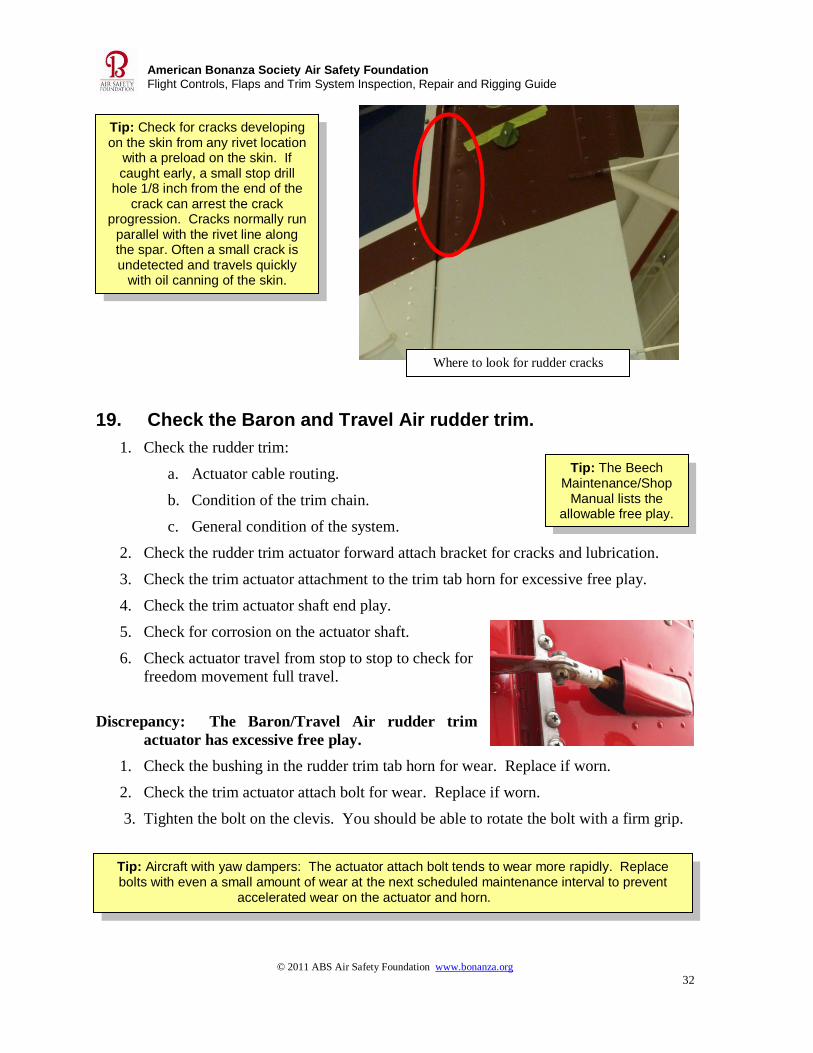
Discrepancy: Cracks appear along the rudder spar hinge line.
© 2011 ABS Air Safety Foundation www.bonanza.org
32
American Bonanza Society Air Safety Foundation
Flight Controls, Flaps and Trim System Inspection, Repair and Rigging Guide
Tip: Check for cracks developing on the skin from any rivet location
with a preload on the skin. If caught early, a small stop drill
hole 1/8 inch from the end of the crack can arrest the crack
progression. Cracks normally run parallel with the rivet line along the spar. Often a small crack is undetected and travels quickly
with oil canning of the skin.
Tip: Aircraft with yaw dampers: The actuator attach bolt tends to wear more rapidly. Replace bolts with even a small amount of wear at the next scheduled maintenance interval to prevent
accelerated wear on the actuator and horn.
Tip: The Beech Maintenance/Shop
Manual lists the allowable free play.
19. Check the Baron and Travel Air rudder trim.
1. Check the rudder trim:
a. Actuator cable routing.
b. Condition of the trim chain.
c. General condition of the system.
2. Check the rudder trim actuator forward attach bracket for cracks and lubrication.
3. Check the trim actuator attachment to the trim tab horn for excessive free play.
4. Check the trim actuator shaft end play.
5. Check for corrosion on the actuator shaft.
6. Check actuator travel from stop to stop to check for
freedom movement full travel.
Discrepancy: The Baron/Travel Air rudder trim
actuator has excessive free play.
1. Check the bushing in the rudder trim tab horn for wear. Replace if worn.
2. Check the trim actuator attach bolt for wear. Replace if worn.
3. Tighten the bolt on the clevis. You should be able to rotate the bolt with a firm grip.
Where to look for rudder cracks
© 2011 ABS Air Safety Foundation www.bonanza.org
33
American Bonanza Society Air Safety Foundation
Flight Controls, Flaps and Trim System Inspection, Repair and Rigging Guide
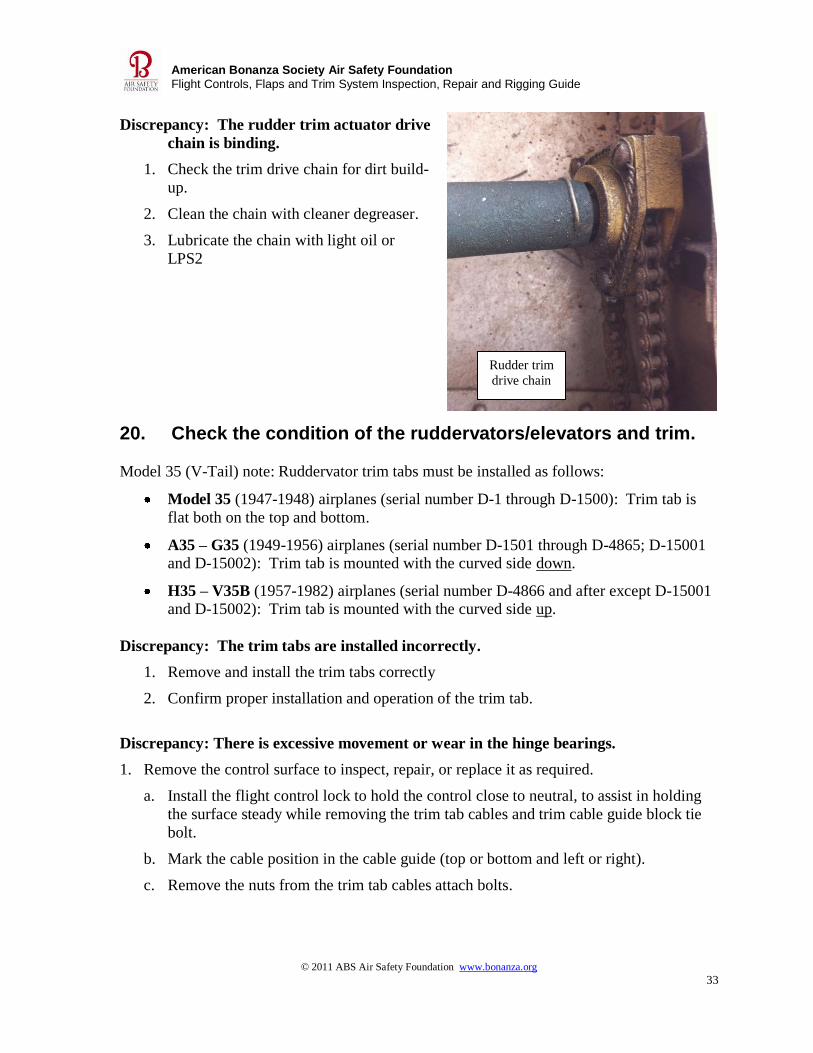
Discrepancy: The rudder trim actuator drive
chain is binding.
1. Check the trim drive chain for dirt build-
up.
2. Clean the chain with cleaner degreaser.
3. Lubricate the chain with light oil or
LPS2
20. Check the condition of the ruddervators/elevators and trim.
Model 35 (V-Tail) note: Ruddervator trim tabs must be installed as follows:
Model 35 (1947-1948) airplanes (serial number D-1 through D-1500): Trim tab is
flat both on the top and bottom.
A35 – G35 (1949-1956) airplanes (serial number D-1501 through D-4865; D-15001 and D-15002): Trim tab is mounted with the curved side down.
H35 – V35B (1957-1982) airplanes (serial number D-4866 and after except D-15001 and D-15002): Trim tab is mounted with the curved side up.
Discrepancy: The trim tabs are installed incorrectly.
1. Remove and install the trim tabs correctly
2. Confirm proper installation and operation of the trim tab.
Discrepancy: There is excessive movement or wear in the hinge bearings.
1. Remove the control surface to inspect, repair, or replace it as required.
a. Install the flight control lock to hold the control close to neutral, to assist in holding
the surface steady while removing the trim tab cables and trim cable guide block tie
bolt.
b. Mark the cable position in the cable guide (top or bottom and left or right).
c. Remove the nuts from the trim tab cables attach bolts.
Rudder trim
drive chain
© 2011 ABS Air Safety Foundation www.bonanza.org
34
American Bonanza Society Air Safety Foundation
Flight Controls, Flaps and Trim System Inspection, Repair and Rigging Guide
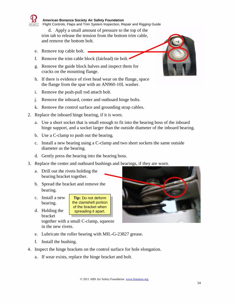
Tip: Do not deform the clamshell portion of the bracket when spreading it apart.
d. Apply a small amount of pressure to the top of the
trim tab to release the tension from the bottom trim cable,
and remove the bottom bolt.
e. Remove top cable bolt.
f. Remove the trim cable block (fairlead) tie bolt.
g. Remove the guide block halves and inspect them for
cracks on the mounting flange.
h. If there is evidence of rivet head wear on the flange, space
the flange from the spar with an AN960-10L washer.
i. Remove the push-pull rod attach bolt.
j. Remove the inboard, center and outboard hinge bolts.
k. Remove the control surface and grounding strap cables.
2. Replace the inboard hinge bearing, if it is worn.
a. Use a short socket that is small enough to fit into the bearing boss of the inboard
hinge support, and a socket larger than the outside diameter of the inboard bearing.
b. Use a C-clamp to push out the bearing.
c. Install a new bearing using a C-clamp and two short sockets the same outside
diameter as the bearing.
d. Gently press the bearing into the bearing boss.
3. Replace the center and outboard bushings and bearings, if they are worn.
a. Drill out the rivets holding the
bearing bracket together.
b. Spread the bracket and remove the
bearing.
c. Install a new
bearing.
d. Holding the
bracket
together with a small C-clamp, squeeze
in the new rivets.
e. Lubricate the roller bearing with MIL-G-23827 grease.
f. Install the bushing.
4. Inspect the hinge brackets on the control surface for hole elongation.
a. If wear exists, replace the hinge bracket and bolt.

© 2011 ABS Air Safety Foundation www.bonanza.org
35
American Bonanza Society Air Safety Foundation
Flight Controls, Flaps and Trim System Inspection, Repair and Rigging Guide
Tip: If the flange hits
the rivets, the flange will break when
tightened.
Tip: Use the same instructions for straight-tail airplanes. Install the trim tab bolt without a washer under the head to ensure good grip length of the bolt through trim tab rod clevis. This may require
two washers.
Tip: Ruddervator and elevator skins are made of magnesium. A maximum of 10% of the skin thickness may be affected by corrosion. Treat magnesium as described in Appendix A.
Most straight-tail aircraft elevators may be re-skinned in aluminum under an STC.
5. Reinstall the control surface.
a. At the inboard bearing location, install:
i. One AN-960-416 washer under the bolt head.
ii. One AN960-416L washer between the torque fitting and the bearing.
iii. One AN960-416 washer under the nut.
b. Torque the nut to 30 to 40 inch-pounds.
i. Use up to 70 inch-pounds to align the cotter pin hole.
ii. Safety the bolts with cotter pins.
c. At the center and outboard bearing locations, install:
i. No washers under the bolt head, to insure good grip length of the bolt through the
hinge bracket.
ii. Two AN960-10 washers under the nut.
d. Torque to 20 to 25 inch-pounds.
i. Use up to 40 inch-pounds to align the cotter pin holes.
ii. Safety the bolts with cotter pins.
e. Install the trim cable guide block.
i. Use an AN960-10L washer under the flange if the block
is hitting the rivet heads next to the flange.
f. Install the trim cables.
i. Use one thin washer under the head of the nut.
ii. Tighten the bolt to where it can be rotated with a firm grip of the fingers.
iii. Safety the clevis screw.
© 2011 ABS Air Safety Foundation www.bonanza.org
36
American Bonanza Society Air Safety Foundation
Flight Controls, Flaps and Trim System Inspection, Repair and Rigging Guide
Tip: Loosen both mounting bolts first, then remove both bolts and the block to prevent
twisting and cracking the anchor nut tab on the bracket.
Tip: Often a step will wear in the brass Acme
thread nut in the actuator. Grease may be
dirty, old, and caked.
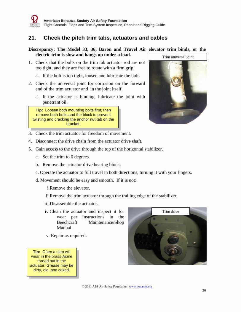
21. Check the pitch trim tabs, actuators and cables Discrepancy: The Model 33, 36, Baron and Travel Air elevator trim binds, or the
electric trim is slow and hangs up under a load.
1. Check that the bolts on the trim tab actuator rod are not
too tight, and they are free to rotate with a firm grip.
a. If the bolt is too tight, loosen and lubricate the bolt.
2. Check the universal joint for corrosion on the forward
end of the trim actuator and in the joint itself.
a. If the actuator is binding, lubricate the joint with
penetrant oil.
3. Check the trim actuator for freedom of movement.
4. Disconnect the drive chain from the actuator drive shaft.
5. Gain access to the drive through the top of the horizontal stabilizer.
a. Set the trim to 0 degrees.
b. Remove the actuator drive bearing block.
c. Operate the actuator to full travel in both directions, turning it with your fingers.
d. Movement should be easy and smooth. If it is not:
i.Remove the elevator.
ii.Remove the trim actuator through the trailing edge of the stabilizer.
iii.Disassemble the actuator.
iv.Clean the actuator and inspect it for
wear per instructions in the
Beechcraft Maintenance/Shop
Manual.
v. Repair as required.
Trim universal joint
Trim drive

© 2011 ABS Air Safety Foundation www.bonanza.org
37
American Bonanza Society Air Safety Foundation
Flight Controls, Flaps and Trim System Inspection, Repair and Rigging Guide
Tip: The bushing can be replaced without
removing the actuator.
vi.Correctly set end play with an adjusting bushing prior to installing the actuator
back into the stabilizer.
vii.Reassemble and install the actuator.
viii.Set the actuator to the proper measurement for 0 degrees.
ix.Attach the trim chain to the tab actuator drive.
x. Check the cockpit indicator is at 0 degrees and the actuator rod end measurement
is correct.
xi. Install both attach bolts in the actuator drive shaft bearing block
xii. Torque the bolts.
xiii. Reinstall the elevator.
Discrepancy: There is excessive trim tab end play.
1. Inspect the clevis ends on the trim actuator rod for wear.
2. Replace worn bolts with correct NAS bolts.
3. Install washers correctly (no washer under the head, 1 to 2 washers under the nut) to
allow the grip length of bolt to extend through the clevis.
4. Tighten to where you can rotate the bolt with a firm grip of
the fingers.
5. Check the elevator trim actuator screw bushing for wear.
a. Set the elevator trim to neutral.
b. Remove the elevator to gain access to the stabilizer trailing edge.
c. Remove the guide for the shoulder pin.
d. Measure the length of the screw between the actuator rod end and the actuator.
e. Remove the snap ring and screw out the actuator screw.
f. Remove the actuator rod end.
g. Replace the bushing and install the rod end.
h. Clean the inside actuator nut with degreaser and a round brush.
i. Lubricate the actuator screw.
j. Install the actuator screw to the measured length.
k. Install the guide.
l. Attach the trim rod.
m. Reinstall the elevator per the Beechcraft Maintenance/Shop Manual.
© 2011 ABS Air Safety Foundation www.bonanza.org
38
American Bonanza Society Air Safety Foundation
Flight Controls, Flaps and Trim System Inspection, Repair and Rigging Guide
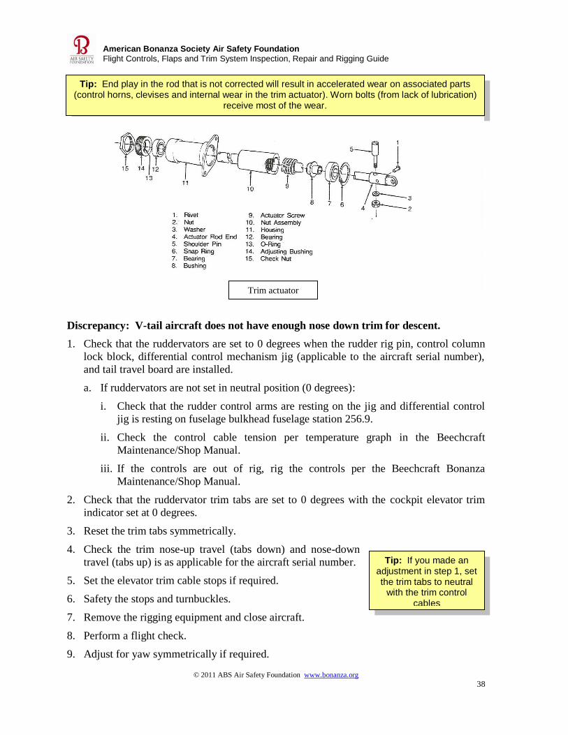
Tip: End play in the rod that is not corrected will result in accelerated wear on associated parts (control horns, clevises and internal wear in the trim actuator). Worn bolts (from lack of lubrication)
receive most of the wear.
Tip: If you made an adjustment in step 1, set the trim tabs to neutral
with the trim control cables
Discrepancy: V-tail aircraft does not have enough nose down trim for descent.
1. Check that the ruddervators are set to 0 degrees when the rudder rig pin, control column
lock block, differential control mechanism jig (applicable to the aircraft serial number),
and tail travel board are installed.
a. If ruddervators are not set in neutral position (0 degrees):
i. Check that the rudder control arms are resting on the jig and differential control
jig is resting on fuselage bulkhead fuselage station 256.9.
ii. Check the control cable tension per temperature graph in the Beechcraft
Maintenance/Shop Manual.
iii. If the controls are out of rig, rig the controls per the Beechcraft Bonanza
Maintenance/Shop Manual.
2. Check that the ruddervator trim tabs are set to 0 degrees with the cockpit elevator trim
indicator set at 0 degrees.
3. Reset the trim tabs symmetrically.
4. Check the trim nose-up travel (tabs down) and nose-down
travel (tabs up) is as applicable for the aircraft serial number.
5. Set the elevator trim cable stops if required.
6. Safety the stops and turnbuckles.
7. Remove the rigging equipment and close aircraft.
8. Perform a flight check.
9. Adjust for yaw symmetrically if required.
Trim actuator
© 2011 ABS Air Safety Foundation www.bonanza.org
39
American Bonanza Society Air Safety Foundation
Flight Controls, Flaps and Trim System Inspection, Repair and Rigging Guide
Tip: Treatment #2 can be performed
immediately following treatment #1, even if the surface is still wet from rinsing off treatment #1.
APPENDIX A Treating magnesium surfaces Elevators/ruddervators, some landing gear components, landing gear extension/retraction
gearboxes, and certain early Bonanza ailerons are made from magnesium.
Corrosion will appear very rapidly on magnesium surfaces if exposed, unpainted surfaces are
not prepared quickly and properly. Magnesium must be thoroughly dried prior to painting.
Anytime sanding or Scotchbrite work is accomplished on a magnesium surface the protective
coating will be removed, and it must be reapplied prior to re-painting.
Magnesium surface treatment
Treatment #1: Corrosion Etching Process. After stripping paint from a magnesium
component:
1. Treat the surface with etching solution if corrosion pitting is present. Appling solution
with a terry wash cloth works well.
2. Treat one unit at a time as it will dry quickly.
3. Rinse the component off thoroughly with water on both the outside and inside of the
surface within 3 to 4 minutes after application, or the solution will be difficult to
remove.
4. Treat additional surfaces and rinse off.
Important: Use instructions and common sense rules when handling chemicals as listed on
the packaging. Review the Material Safety Data Sheets and wear all recommended protective
equipment. Follow local rules on handling and disposing of chemicals.
Magnesium Corrosion Etch recipe mix
Chromic acid (flakes, not crystals-flakes dissolve better) 1 pound
Nitric Acid, 1.4 specific gravity strength 0.9 pint/426cc/1.3 lbs.
Water 1 gallon
Solution #1 cannot be stored, mix only enough for required use. 1/4th
of the above recipe
is sufficient to treat two elevators.
Treatment #2 Corrosion Preventive Process
After corrosion etching, or at any time the golden color has been
removed by scratching, sanding or the use of a Scotchbrite pad,
treat the surface with a corrosion preventive process.
© 2011 ABS Air Safety Foundation www.bonanza.org
40
American Bonanza Society Air Safety Foundation
Flight Controls, Flaps and Trim System Inspection, Repair and Rigging Guide
Tip: This solution may be stored for up to
one year.
Corrosion Preventive Solution recipe mix
Place ¾ gallon of 73°F to 90°F water in a stainless steel, aluminum, or vinyl polyethylene
container which will measure 1 gallon of fluid.
Add 1.33 once of chromic acid (CrO or H2CrO4)) flakes.
Add 1 once of calcium sulfate powder (CaSO) to the water.
Add water to make 1 gallon of solution, stir vigorously for at least
15 minutes.
Important: Use instructions and common sense rules when handling chemicals as listed on
the packaging. Review the Material Safety Data Sheets and wear all recommended protective
equipment. Follow local rules on handling and disposing of chemicals.
1. Apply the solution to magnesium surfaces with a white terry wash cloth.
2. Rinse the component thoroughly with water on both the outside inside surfaces.
3. Allow three or more days of drying time, or use drying units in a heated room prior to
priming and painting. More time may be required in cool or humid weather..
4. Magnesium is porous and must be thoroughly dried prior to finishing with paint, or
moisture will be trapped beneath primer and paint and corrosion will reappear.
5. Normal paint processes and products may then be used for surface finishing.

© 2011 ABS Air Safety Foundation www.bonanza.org
41
American Bonanza Society Air Safety Foundation
Flight Controls, Flaps and Trim System Inspection, Repair and Rigging Guide
Appendix B Addressing a Wing-Heavy Condition
The process of solving a wing-heavy condition or an aircraft that feels heavy on the controls
(requiring cross-controlling to hold the aircraft straight) takes an intelligent, coordinated
effort.
Mechanics often approach a wing-heavy condition by treating the symptom and not the
cause. But this introduces other conditions during the process. Sometimes an aircraft comes
out of manufacturing out of rig. Other times maintenance or modification introduces rigging
changes (for instance, a rod end change, adjusting cable tensions, repairing or replacing a
control surface, etc.). Subtle changes over time add up.
In Barons and Travel Airs, differential power after installing a new engine can give the
appearance of a rigging problem. If the older engine has an extremely worn throttle stop, at
full throttle the throttle plate goes past center and restricts MAP an inch or two. In flight the
apparent fix is to apply rudder and aileron trim, but airframe rigging is not the cause.
Severe turbulence can bend and cause washout on a wing that is not noticeable by sight, but
is measureable with a transit. We have seen this happen where control wheel position was
dramatically different before and after encountering turbulence. The problem can come on
subtly over time with flight in turbulence. Often this can be corrected by remounting the
wing, but it can be so severe as to require wing replacement.
Checking the rig
On the ground, review the aircraft for the static rigging condition:
1. Is the turn coordinator mounted so it is level in the instrument panel when the aircraft
is level?
2. Center the nose wheel. Is/are the rudder/ruddervator balance horn(s) even with the
fixed stabilizer? Sometimes you will find a rudder “cheating” to the left a couple of
degrees.
3. How much is the ground-adjustable rudder trim bent? Normally it is deflected to the
right when looking forward.
4. Lift the glare shield.
a. Single-column controls: check whether the torque knee is at the 12 o’clock
position when the control wheel is centered.
b. 1984 and after Be36 and Baron 58 models: check to see if the left and right
control wheels are level.
5. Are the aileron trailing edges aligned with the wing tip and the flap training edge
when the control wheel is level? (Caution, sometimes a reskinned aileron’s trailing
edge is not straight).

© 2011 ABS Air Safety Foundation www.bonanza.org
42
American Bonanza Society Air Safety Foundation
Flight Controls, Flaps and Trim System Inspection, Repair and Rigging Guide
6. How much is/are the ground-adjustable aileron trim tabs bent?
7. Barons, Travel Airs and 1984 and later Be36s: Is the flight adjustable aileron trim tab
aligned with the aileron when the cockpit trim control is centered?
8. Check if the flaps are aligned with the bottom of the fuselage when retracted. Are the
flaps up tight in flap well? Is one trailing edge lower than the other?
9. Check whether the inboard elevator ribs are level with each other.
10. Check whether the elevator/ruddervator trim tab trailing edges are even. On later
Model 36s there is a couple of degrees difference between the elevator trim tabs.
11. Remove the aft, lower wing bolt covers. Check the position of the wings fittings.
Are they even, or is one up and the other one down?
Before making any adjustment, conduct a pre-maintenance test flight:
1. On throwover-control airplanes (including those with dual controls installed), remove
the control trimmer so it will not affect the ailerons during the test flight.
2. Check that the tapered stop cone on the forward end of the nose steering yoke bolt is
free to rotate using your fingers. If this bolt is too tight and the cone is not free to
rotate, it can displace the slip/skid ball slightly.
3. Adjust fuel as necessary to have the fuel load balanced in both wings as closely as
possible.
4. Conduct a flight with the owner/pilot.
5. Start taking notes at takeoff: do the ailerons seek a position other than level on
departure?
6. In clear, smooth air, level the aircraft, set power for normal cruise flight and speed,
and trim to hold altitude.
7. Check the position of the control wheel.
8. Check the position of the ailerons in relationship to wingtips and flaps.
9. With feet off the rudder pedals, what is the position of the slip/skid ball; is the
airplane holding heading?
10. If a wing is heavy and the ball is out of center, does centering the ball lift the heavy
wing?
11. Enter a standard rate turn. Trim the nose to hold altitude and release the controls and
rudder pedals. Does the aircraft stay in the turn for a couple of circles? Do this in
both directions.
12. Enter a normal descent. Select approach flaps if the aircraft is so equipped. Does the
aircraft roll in this condition? If so, a flap may have been adjusted to help correct a
wing heavy condition during cruise.
© 2011 ABS Air Safety Foundation www.bonanza.org
43
American Bonanza Society Air Safety Foundation
Flight Controls, Flaps and Trim System Inspection, Repair and Rigging Guide
Compare notes on the static and flight reviews to develop an action plan.
1. It’s important to neutralize the control surfaces with the control wheel centered and
cable tensions correct.
2. Ensure aileron ground adjustable tabs are straight, at 0 degrees.
3. Adjust the rudder trim tab as the rigging progresses. If the tab is bent more than 45
degrees, straighten the tab to 45° or less.
4. Verify the turn coordinator is mounted precisely level in the panel with the aircraft
level.
If the ailerons and control wheel are level on the ground, but seek another position
(especially about 10 degrees to the right or left) on the initial climb-out, the wing will need to
be moved to correct this condition.
Wing Repositioning
Correctly adjusting the wing mounting is done by trial and error. You may hit it right on the
first movement, or it may take several wing adjustments to fully correct a wing heavy
condition.
Have plenty of crush washers on hand for the top wing bolts when you start the project.
Crush washers must be replaced on every wing movement.
Raise the wing trailing edge opposite the heavy wing first. This will speed the process, and a
smaller section of paint line will need to be touched up along the wing root seal. Rig the
aircraft as closely as possible with the wing movement before trimming out the heaviness
with tabs and flaps, as when you move the wing position this will also affect yaw.
Nothing needs to be disconnected during this procedure except for the wing bolts. Remove
the top two wing-bolt nuts and slide them inboard to replace the crush washers when the
wing is allowed to sag about 1/8” at the wing root. The bottom two bolts need to be loosened
about 3/32nd
of an inch.
The lower, forward wing bolt is a close fit. The wing rotates on this bolt. When retorquing
this bolt it should float left and right without binding. The other three bolts are smaller than
the bolt bore to allow for angle of incidence adjustment. The top two wing attach bolts hold
the wing position with crush washers. Replace the crush washers every time the wing is
moved.
Note: If the wing bolts have never been replaced, this is a good time to accomplish this task.
To adjust a wing:
1. Remove the seats to gain access to the top wing bolts.
2. Jack the aircraft until the main wheels are just off the floor (you can see daylight beneath
them).
© 2011 ABS Air Safety Foundation www.bonanza.org
44
American Bonanza Society Air Safety Foundation
Flight Controls, Flaps and Trim System Inspection, Repair and Rigging Guide
3. Secure tail so the airplane does not bounce up and down
4. Support the wing not being moved with a tripod jack and a block of wood outboard by
the wing tiedown lug on the lower spar cap.
5. Support the wing being moved with a tripod jack and block of wood by the wing
tiedown lug on the lower spar cap.
6. Place a second tripod jack and wood block under the wing being moved to support the
wing inboard of the main gear strut on the lower spar cap. This jack will be used to
adjust the lower forward fitting to ensure this wing bolt will freely float left and right
prior to torquing. There will be no pressure on this jack when allowing the wing to sag.
7. The trailing edge of the wing is light and can be supported by a single individual.
8. Once the aircraft and wing are supported, decide how much you want to move the wing
and mark the fuselage to that relocation point. Remember this is trial and error.
9. Use a piece of aluminum as a 1”x3” template. Set the template on top of the aft wing bolt
fitting between the wing root seal and the fuselage. Mark the distance you want to move
the wing on the the fuselage with masking tape.
10. Attach several crush washers for the top wing bolt fittings to a section of ¾” masking
tape so the washers are easily available on top of the wing for installation.
11. Loosen the lower wing bolts first, about 3/32”.
12. Clean and lubricate the bolts with MIL-C16173, grade ll corrosion preventive compound,
if they have not been previously treated.
13. Reinstall the bolts to 3/32”endplay.
14. Check that the jacks at the wing tiedowns are lightly preloading the wings.
15. Loosen the top aft wing bolt and remove its nut. Note the radius washer orientation.
16. Clean and lubricate the bolts as required.
17. Inspect the fittings and address any damage.
18. Have an individual support the wing at the flap trailing edge in the area of the boarding
step.
19. Loosen the top forward wing bolt. Watch the fitting separation from the fuselage. You
should not see much movement.
20. Remove the nut. Note the radius washer orientation.
21. Clean and lubricate the bolt if required.
22. Inspect the fittings and address any damage.
23. Allow the wing to sag about 1/8th
inch. Place your finger in the top forward bolt bore and
use a narrow 6” rule to work the crush washer free from the fitting. Grasp the washer
with a hemostat and remove it.
24. Install a new washer and reinstall the bolt, washers and nut.

© 2011 ABS Air Safety Foundation www.bonanza.org
45
American Bonanza Society Air Safety Foundation
Flight Controls, Flaps and Trim System Inspection, Repair and Rigging Guide
25. Tighten the bolt enough to seat it against the outboard fitting and support the wing.
26. Replace the top aft wing bolt crush washer in the same manner. You may have to apply
some forward pressure on both wing tips to get the gap to open up enough to get the
crush washer free.
27. Reinstall the bolt radius washer and nut. Tighten it to outboard wing fitting. Use a
magnet to assist in pulling the bolt back into the bore.
28. Jack up the wing you moved at the tiedown to take the sag out of wing.
29. Apply pressure to the inboard jack to ensure there is no binding of the lower forward
wing bolt when it floats freely left and right.
30. Set trailing edge of the wing to the selected relocation point.
31. Tighten the top forward wing bolt first, and then the aft top bolt enough to hold wing
from moving.
32. Recheck that the lower forward bolt is not binding, but is free to move.
33. Torque the top bolts and the bottom bolt to wet torque specifications.
34. Apply a “wet torque” placard on the fuselage.
35. Take the aircraft off the jacks.
36. Reassemble the panels and interior.
Perform a post-maintenance flight to check any change in the wing-heavy condition. Take
notes just as you did on the pre-maintenance flight. Yaw may need to be readjusted with the
wing movement. Repeat the entire process as necessary until the airplane is rigged to the
owner’s satisfaction.
The process seems long, but after the first time a couple of guys can move a wing in a couple
of hours.
Often one wing is moved all the way up in its bolt bores and the other wing mounts lower
down in its bolt bores to fine-tune the flight characteristics.
Perfect rigging is never an accident. It is a result of intelligent effort.