Embed Size (px)
Citation preview
© Danfoss | 2016.04 VD.IR.P2.02 | 1
Data sheet
Actuator for modulating & 3-point control AME 685 – without safety function
The actuator is designed to control the valve in response to the demand of a controller in District Heating/cooling, Heating, Ventilating and Air conditioning systems.
The AME 685 can be controlled by electronic controllers with modulating or 3-point control output.
Actuator can be used in combination with:Valve type VF 3 (DN 200-300)
Features:• Manual operation mechanical and/or electrical• Position indication, LED signalization• Selectable speed 2,7 or 6 s/mm• Automatic adaptation of stroke to valve’s end
positions that reduces commissioning time (self stroking)
• Integrated auxiliary switch• Characteristic optimization• Adjustable stroke limitation• Anti-oscillation function• Pulse or continuous output signal (4 & 5)• Voltage or current output signal X• External reset button• Auto detection of Y signal• 3-point or modulating control selection• Galvanic insulation Y & X and output terminal
(4 & 5)• Thermal and overload protection• Precise control and fast response in 3-point
mode (0,01 s)
Main data:• Nominal voltage (AC or DC):
- 24 V, 50 Hz/60 Hz- 230 V, 50 Hz/60 Hz
• Control input signal: modulating or 3-point• Force: 5000 N• Stroke: 80 mm• Speed (selectable): 2,7 or 6 s/mm• Max. medium temperature: 200 °C
Actuator
Picture TypePower supply
(V) Code No.
AME 685
24 082G3500
230 082G3501
Accessories - Stem heaterType DN Code No.
Stem heater for VF3 valve 200-300 065Z7021
Ordering
Description
Data sheet AME 685
2 | © Danfoss | 2016.04 VD.IR.P2.02
①
③
⑤
②
④
⑥
⑦
Power supply V 24 or 230; +10 … –15 %; AC or DC
Power consumption VA 35 (24 V)50 (230 V)
Signal mA 10
Frequency Hz 50/60
Control input Y
V 0-10 (2-10) [Ri = 100 kΩ]
mA 0-20 (4-20) [Ri = 500 Ω]
3-point (wiring auto-detection)
Control output XV 0-10 (2-10) [Ri = 2 kΩ]
mA 0-20 (4-20) [Ri = 550 Ω]
Closing force N 5000
Max. stroke mm 80
Speed (selectable) s/mm 2,7 or 6
Max. medium temperature
°C
200
Ambient temperature 0 … + 55
Storage and transport temperature −40 … +70 (storing for 3 days)
Humidity 5-95%
Protection class II
Grade of enclosure IP 54
Weight kg 7,5
Manual operation Electrical and mechanical
Power failure response Stem remains in last position
- marking in accordance with the standards
Low Voltage Directive 2006/95/EECEMC Directive 2004/108/EEC
Technical data
Please check power supply and power consumption prior connection!
The actuator must be dismantled and the elements sorted into various material groups before disposal.
Disposal Before disassembly please contact Danfoss support for disassembly instructions.
Complete the mechanical and electrical installation (see instructions) and perform the necessary checks and tests:
- Turn on the power- Set the appropriate control signal and check
that the valve stem direction is correct for the application.
The unit is now fully commissioned.
Commissioning
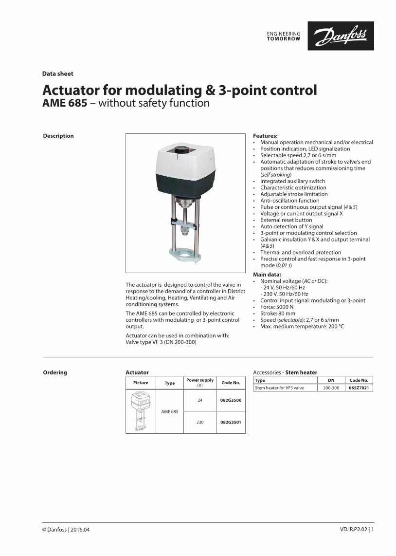
Design
1. Manual operation knob 2. Function buttons 3. Service cover 4. Removable gland support 5. End position indication ring 6. Stem connector 7. Valve connector (yoke)
Data sheet AME 685
© Danfoss | 2016.04 | 3VD.IR.P2.02
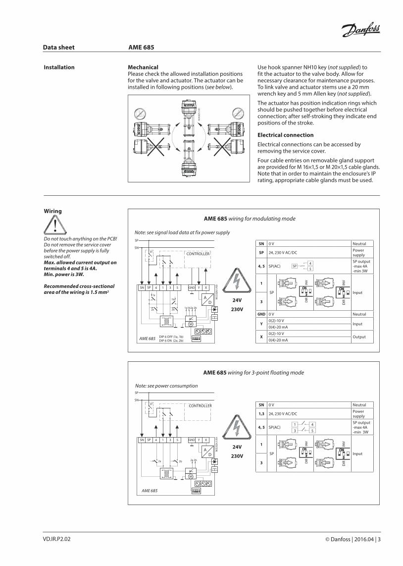
AME 685 DIP 6 OFF (1a, 1b)DIP 6 ON (2a, 2b)
SN 0 V Neutral
SP 24, 230 V AC/DC Power supply
4, 5 SP(AC)4
5SP
SP output-max 4A -min 3W
1
SP
Input
3
GND 0 V Neutral
Y0(2)-10 V
Input0(4)-20 mA
X0(2)-10 V
Output0(4)-20 mA
CONTROLLER
24V
230V
Note: see signal load data at fix power supply
AME 685 wiring for modulating mode
AME 685 wiring for 3-point floating mode
SN 0 V Neutral
1,3 24, 230 V AC/DC Power supply
4, 5 SP(AC)4
5
1
3
SP output-max 4A -min 3W
1
SP
Input
3
AME 685
CONTROLLER
Note: see power consumption
Wiring
Do not touch anything on the PCB! Do not remove the service cover before the power supply is fully switched off.Max. allowed current output on terminals 4 and 5 is 4A. Min. power is 3W.
Recommended cross-sectional area of the wiring is 1.5 mm2
24V
230V
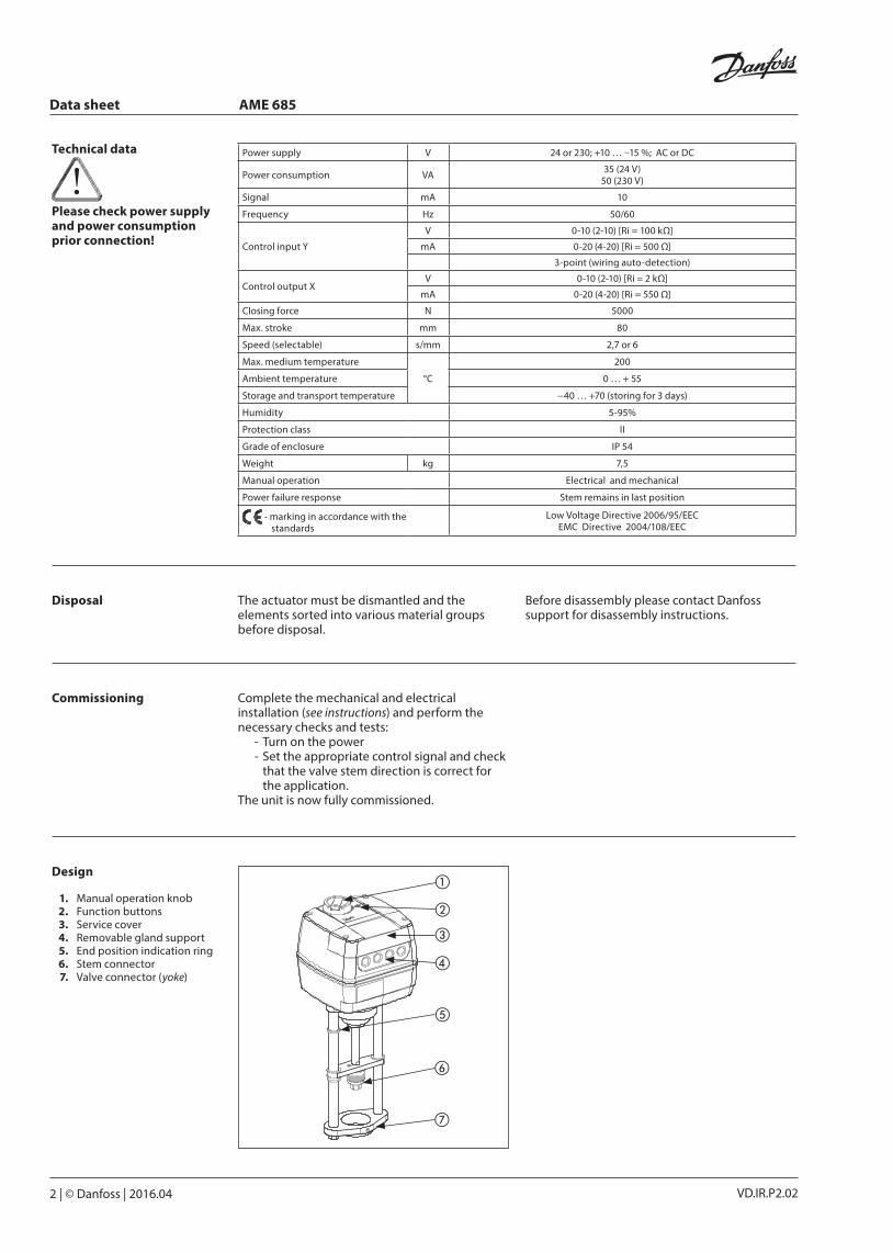
Installation Mechanical Please check the allowed installation positions for the valve and actuator. The actuator can be installed in following positions (see below).
Use hook spanner NH10 key (not supplied) to fit the actuator to the valve body. Allow for necessary clearance for maintenance purposes. To link valve and actuator stems use a 20 mm wrench key and 5 mm Allen key (not supplied).
The actuator has position indication rings which should be pushed together before electrical connection; after self-stroking they indicate end positions of the stroke.
Electrical connection
Electrical connections can be accessed by removing the service cover.
Four cable entries on removable gland support are provided for M 16×1,5 or M 20×1,5 cable glands. Note that in order to maintain the enclosure’s IP rating, appropriate cable glands must be used.
Data sheet AME 685
4 | © Danfoss | 2016.04 VD.IR.P2.02
Actuator operating modes LED operating mode indicatorThe three-colour (green/yellow/red) LED function indicators are located on the actuator cover. They indicate different operating modes.
RESET buttonActuator have external RESET button which is located on top cover of the actuator next to LED indicators. With this button you can enter or exit Stand-By mode (press once) or Self stroking mode (press and hold for 5 seconds). See next paragraph for mode details.
Operating modes• Self stroking mode Self stroking mode starts automatically the
first time when power supply is applied to the actuator. To start self stroking procedure press and hold RESET button for 5 seconds until the green light starts flashing. End positions of the valve are automatically set and the actuator goes to stationary mode and starts responding to the control signal.
• Stand-By mode Press the RESET button for 1 sec. to enter Stand-By mode. The actuator stops in current position and stops responding
to any control signal. Red light is constantly lit. You can manually operate the actuator with mechanical handle or control buttons. This mode can be very useful during the commissioning of other equipment, or for service purposes. In this mode you can also set positions of the additional switches. To exit Stand-By mode press the RESET button again.
• Positioning mode The actuator is operating automatically. The stem is extending or retracting according to the control signal. When positioning is finished the actuator goes to stationary mode. If for one or another reason 3-point signal (terminals 1 and 3) and Y signal would be present at the same time, 3-point signal would prevail.
• Stationary mode The actuator is operating without errors.
• Error mode Working temperature is too high - check the ambient temperature.
Stroke is too short - check the connection with valve and valve operation, or check if valve is blocked.
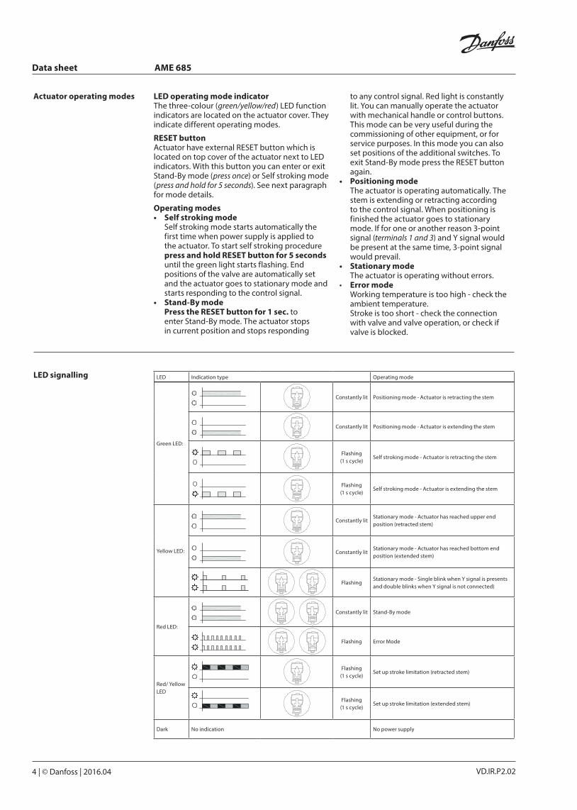
LED Indication type Operating mode
Green LED:
Constantly lit Positioning mode - Actuator is retracting the stem
Constantly lit Positioning mode - Actuator is extending the stem
Flashing(1 s cycle)
Self stroking mode - Actuator is retracting the stem
Flashing(1 s cycle)
Self stroking mode - Actuator is extending the stem
Yellow LED:
Constantly litStationary mode - Actuator has reached upper end position (retracted stem)
Constantly litStationary mode - Actuator has reached bottom end position (extended stem)
FlashingStationary mode - Single blink when Y signal is presents and double blinks when Y signal is not connected)
Red LED:
Constantly lit Stand-By mode
Flashing Error Mode
Red/ Yellow LED
Flashing(1 s cycle)
Set up stroke limitation (retracted stem)
Flashing(1 s cycle)
Set up stroke limitation (extended stem)
Dark No indication No power supply
LED signalling
Data sheet AME 685
© Danfoss | 2016.04 | 5VD.IR.P2.02
Q
CM CM CM
Y
Set new retract
Max. retracted
max. extended
Set new extended
Kv
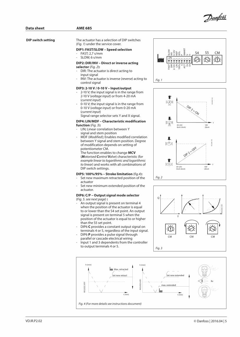
DIP switch setting The actuator has a selection of DIP switches (Fig. 1) under the service cover.
DIP1: FAST/SLOW – Speed selection - FAST; 2,7 s/mm- SLOW; 6 s/mm
DIP2: DIR/INV – Direct or inverse actingselector (Fig. 2):- DIR: The actuator is direct acting to input signal- INV: The actuator is inverse (reverse) acting to
control signal
DIP3: 2-10 V / 0-10 V – Input/output- 2-10 V; the input signal is in the range from
2-10 V (voltage input) or from 4-20 mA (current input)
- 0-10 V; the input signal is in the range from 0-10 V (voltage input) or from 0-20 mA (current input) Signal range selector sets Y and X signal.
DIP4: LIN/MDF – Characteristic modification function (Fig. 3): - LIN; Linear correlation between Y
signal and stem position- MDF (Modified); Enables modified correlation
between Y signal and stem position. Degree of modification depends on setting of potentiometer CM.
The function enables to change MCV (Motorised Control Valve) characteristic (for example linear to logarithmic and logarithmic to linear) and works with all combinations of DIP switch settings.
DIP5: 100%/95% – Stroke limitation (fig.4):- Set new maximum retracted position of the
actuator- Set new minimum extended position of the
actuator.
DIP6: C/P – Output signal mode selector (Fig. 5. see next page) : - An output signal is present on terminal 4
when the position of the actuator is equal to or lower than the S4 set point. An output signal is present on terminal 5 when the position of the actuator is equal to or higher than the S5 set point.
- DIP6 C provides a constant output signal on terminals 4 or 5, regardless of the input signal.
- DIP6 P provides a pulse signal through parallel or cascade electrical wiring
- Input 1 and 3 dependents from the controller to output terminals 4 or 5.
Fig. 1
Fig. 3
Fig. 2
Fig. 4 (For more details see instructions document)
Data sheet AME 685
6 | © Danfoss | 2016.04 VD.IR.P2.02
S4 S5
Fig. 5
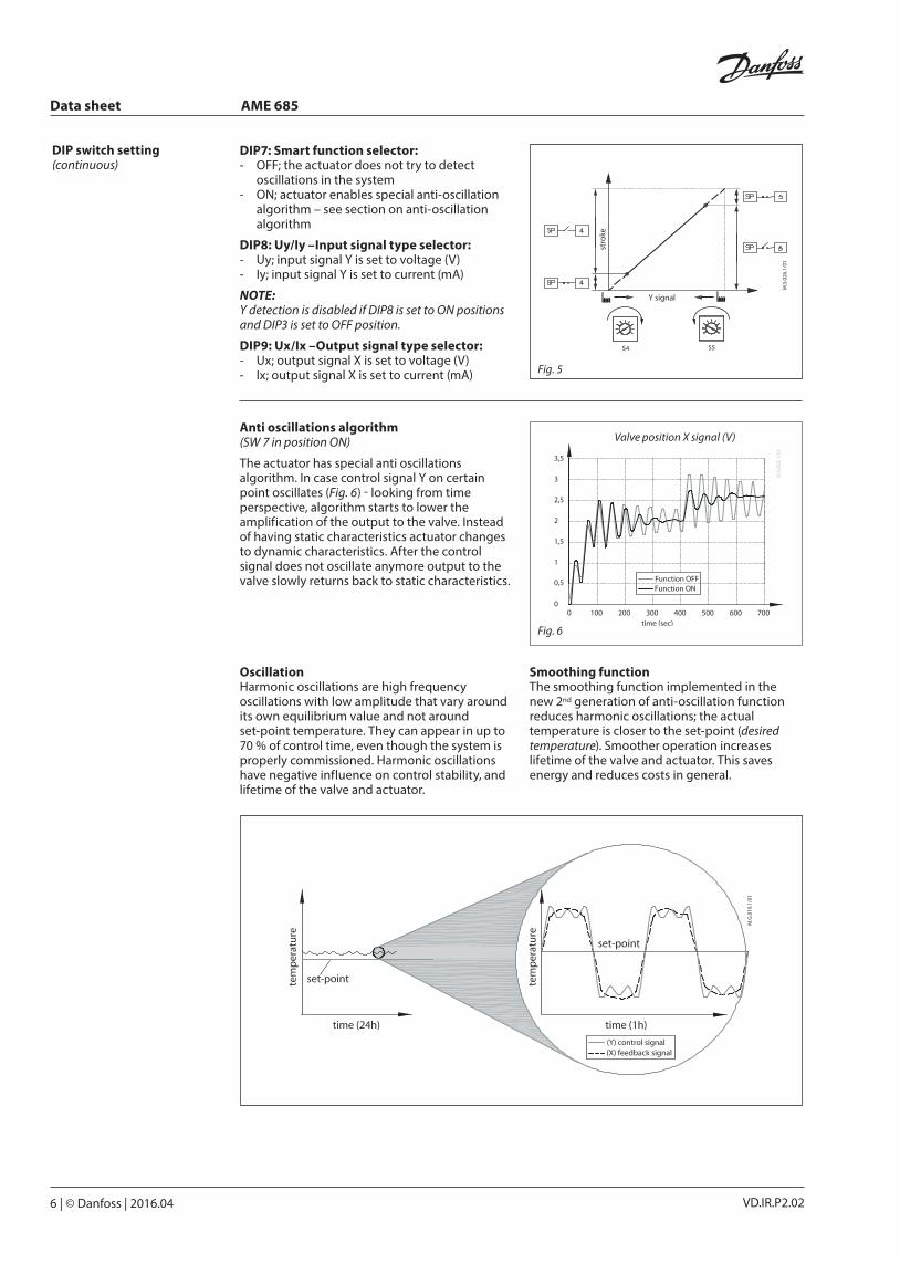
DIP7: Smart function selector: - OFF; the actuator does not try to detect
oscillations in the system- ON; actuator enables special anti-oscillation
algorithm – see section on anti-oscillation algorithm
DIP8: Uy/Iy –Input signal type selector: - Uy; input signal Y is set to voltage (V)- Iy; input signal Y is set to current (mA)
NOTE:Y detection is disabled if DIP8 is set to ON positions and DIP3 is set to OFF position.
DIP9: Ux/Ix –Output signal type selector: - Ux; output signal X is set to voltage (V)- Ix; output signal X is set to current (mA)
DIP switch setting (continuous)
Valve position X signal (V)
Fig. 6
Anti oscillations algorithm(SW 7 in position ON)
The actuator has special anti oscillations algorithm. In case control signal Y on certain point oscillates (Fig. 6) - looking from time perspective, algorithm starts to lower the amplification of the output to the valve. Instead of having static characteristics actuator changes to dynamic characteristics. After the control signal does not oscillate anymore output to the valve slowly returns back to static characteristics.
OscillationHarmonic oscillations are high frequency oscillations with low amplitude that vary around its own equilibrium value and not around set-point temperature. They can appear in up to 70 % of control time, even though the system is properly commissioned. Harmonic oscillations have negative influence on control stability, and lifetime of the valve and actuator.
Smoothing functionThe smoothing function implemented in the new 2nd generation of anti-oscillation function reduces harmonic oscillations; the actual temperature is closer to the set-point (desired temperature). Smoother operation increases lifetime of the valve and actuator. This saves energy and reduces costs in general.
Data sheet AME 685
© Danfoss | 2016.04 | 7VD.IR.P2.02
A
B
B
A
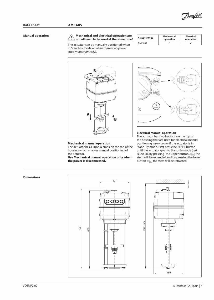
191Dimensions
The actuator can be manually positioned when in Stand-By mode or when there is no power supply (mechanically).
Manual operationActuator type Mechanical
operationElectrical operation
AME 685
Mechanical manual operationThe actuator has a knob & crank on the top of the housing which enables manual positioning of the actuator. Use Mechanical manual operation only when the power is disconnected.
Electrical manual operationThe actuator has two buttons on the top of the housing that are used for electrical manual positioning (up or down) if the actuator is in Stand-By mode. First press the RESET button until the actuator goes to Stand-By mode (red LED is lit). By pressing the upper button the stem will be extended and by pressing the lower button the stem will be retracted.
Mechanical and electrical operation are not allowed to be used at the same time!
493
478
min
. 575
186
VD.IR.P2.028 | © Danfoss | DHS-SRMT/SI | 2016.04
Danfoss can accept no responsibility for possible errors in catalogues, brochures and other printed material. Danfoss reserves the right to alter its products without notice. This also applies to products already on order provided that such alterations can be made without subsequential changes being necessary eady agreed.All trademarks in this material are property of the respective companies. Danfoss and the Danfoss logotype are trademarks of Danfoss A/S. All rights reserved.
Data sheet AME 685
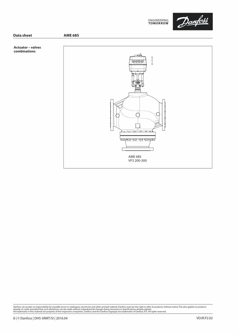
Actuator – valves combinations
AME 685 VF3 200-300