Embed Size (px)
Citation preview
ARD-AYCE65BRFID - Proximity Card Reader
en Installation manual


ARD-AYCE65B Table of Contents | en 3
Bosch Sicherheitssysteme GmbH Installation manual | V 1.1 | 2009.08
Table of Contents
1 General Information 51.1 Introduction 51.2 Box Content 5
2 Technical Specifications 62.1 Key Features 7
3 Installation 83.1 Mounting the ARD-AYCE65B 8
4 Wiring Instructions 9
5 Reader Functionality 115.1 Transmit Mode 115.2 Programming the ARD-AYCE65B Series 115.3 Selecting Keypad Transmission Format 135.3.1 Option No. 1: Single Key, 6-Bit Wiegand 155.3.2 Option No. 2: Single Key, 6-Bit Wiegand Nibble and Parities 155.3.3 Option No. 3: Single Key, 8-Bit Wiegand Nibbles Complemented
165.3.4 Option No. 4: 4 Keys Binary + Facility Code, 26-Bit Wiegand 165.3.5 Option No. 5: 1 to 5 Keys + Facility Code, 26-Bit Wiegand 175.3.6 Option No. 6: 6 Keys BCD and parity bits, 26-Bit Wiegand 185.3.7 Option No. 7: Single Key, 3x4 Matrix Keypad (ARD-MDP64) 195.3.8 Option No. 8: 1 to 8 Keys BCD, Clock & Data 195.4 Selecting Proximity Card Transmission Format 205.5 "Wiegand Card + PIN" Transmission Format 215.6 Changing the Programming Code 225.7 Changing the Facility Code 235.8 Setting the Backlight 235.9 Return to Factory Default Settings 245.10 Replacing a Lost Programming Code 24

4 en | Table of Contents ARD-AYCE65B
| V 1.1 | 2009.08 Installation manual Bosch Sicherheitssysteme GmbH
6 Appendix 256.1 LED displays 256.2 Technical Support 27

ARD-AYCE65B General Information | en 5
Bosch Sicherheitssysteme GmbH Installation manual | V 1.1 | 2009.08
1 General Information
1.1 IntroductionThe ARD-AYCE65B family is an Ultra-slim, vandal-resistant, Piezo Mullion Keypad, access control reader.The unit is vandal resistant and water resistant, suitable for indoor or outdoor mounting. This manual contains the following information:– Installation– Wiring instructions– Operation Instructions
1.2 Box ContentBefore beginning verify that all of the following is in the box. If anything is missing, please report the discrepancy to your nearest Bosch office.– One ARD-AYCE65B unit– Installation kit– Installation and operating instructions

6 en | Technical Specifications ARD-AYCE65B
| V 1.1 | 2009.08 Installation manual Bosch Sicherheitssysteme GmbH
2 Technical SpecificationsSpecifications ARD-AYCE65B
Electrical Characteristics
Power supply type Linear type - recommended
Operating voltage range 5 - 16VDC
Input current standby 92mA@12VDC
max Input current 105mA@16VDC
LED control input Dry contact N.O.
Tamper output Open collector, active low, 30mA max sink current
Cable distance to host controller
Up to 500ft (150 meters) using an 18AWG cable
Max proximity card read range*
40mm (1.575 inch)
Proximity card modulation
ASK at 125 KHz
Proximity card compatibility
EM cards
Card Transmit format (Reader)
26-bit Wiegand, or Clock & Data
Keypad Transmit Format (Reader)
Programmable PIN code formats
LED indicators Two tri-colored LEDs
Communication Data1/Clock, Data0/Data- TTL output
Environmental Characteristics
Operating temp. range -30 to 65° C (-22 to 150° F)
Operating humidity 0 - 95% (non-condensing)
Outdoor usage Weather-resistant, meets IP-68, epoxy potted, suitable for outdoor use
Mechanical
ARD-AYCE65B Technical Specifications | en 7
Bosch Sicherheitssysteme GmbH Installation manual | V 1.1 | 2009.08
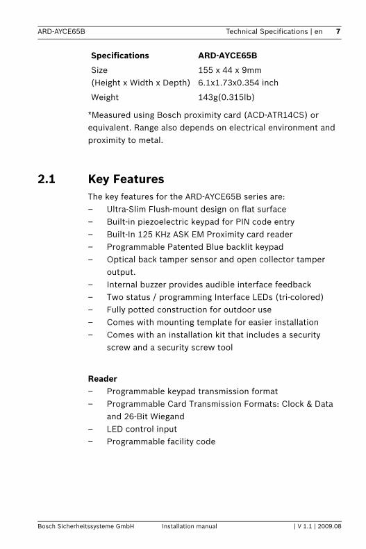
*Measured using Bosch proximity card (ACD-ATR14CS) or equivalent. Range also depends on electrical environment and proximity to metal.
2.1 Key FeaturesThe key features for the ARD-AYCE65B series are:– Ultra-Slim Flush-mount design on flat surface– Built-in piezoelectric keypad for PIN code entry – Built-In 125 KHz ASK EM Proximity card reader– Programmable Patented Blue backlit keypad – Optical back tamper sensor and open collector tamper
output.– Internal buzzer provides audible interface feedback– Two status / programming Interface LEDs (tri-colored)– Fully potted construction for outdoor use– Comes with mounting template for easier installation– Comes with an installation kit that includes a security
screw and a security screw tool
Reader– Programmable keypad transmission format– Programmable Card Transmission Formats: Clock & Data
and 26-Bit Wiegand – LED control input– Programmable facility code
Size (Height x Width x Depth)
155 x 44 x 9mm 6.1x1.73x0.354 inch
Weight 143g(0.315lb)
Specifications ARD-AYCE65B

8 en | Installation ARD-AYCE65B
| V 1.1 | 2009.08 Installation manual Bosch Sicherheitssysteme GmbH
3 InstallationBefore starting, select the location to mount the ARD-AYCE65B. This location should be at shoulder height. For wall mounting, use the included mounting template as a guide for drilling holes for mounting screws and wiring. For US Gang Box mounting, no drilling is necessary.
Figure 3.1 Drilling & Mounting Template
Route the interface cable from the ARD-AYCE65B to the controller. A linear type power supply is recommended. Screw the ARD-AYCE65B to its mounting location or US gang box.

ARD-AYCE65B Wiring Instructions | en 9
Bosch Sicherheitssysteme GmbH Installation manual | V 1.1 | 2009.08
4 Wiring InstructionsThe unit is supplied with a 1.5 meter (60-inch) pigtail, having a 6-conductor cable. To connect the unit to the controller, perform the following:Prepare the unit's cable by cutting the cable jacket back 1¼ inches and strip the wire ½ inch. Prepare the controller cable by cutting the cable jacket back 1¼ inches and strip the wire ½ inch.Splice the unit's pigtail wires to the corresponding controller wires and cover each connection.Refer to the wire color table below, and to the wiring diagram provided on the following page.
If the tamper output is used, connect the purple wire to the correct input on the controller. Trim and cover all unused conductors.
Reader Color Functionality
5~16 VDC Red +DC Input
Shield/ Ground Black Ground
Data 1 / Clock White Communication
Data 0 / Data Green Communication
LEDCTL Brown LED Control / Auxiliary Input
Tamper Purple Tamper

10 en | Wiring Instructions ARD-AYCE65B
| V 1.1 | 2009.08 Installation manual Bosch Sicherheitssysteme GmbH
Figure 4.1 Reader Application Wiring Diagram
NOTICE! – The individual wires from the unit are color-coded
according the Wiegand standard.– When using a separate Power Supply for the Reader, this
Power Supply and that of the Controller must have a common ground.
– The Reader's cable shield wire should preferably be attached to an earth ground, or a signal ground connection at the panel, or power supply end of the cable. This configuration is best for shielding the Reader cable from external interference

ARD-AYCE65B Reader Functionality | en 11
Bosch Sicherheitssysteme GmbH Installation manual | V 1.1 | 2009.08
5 Reader FunctionalityThe following explains how to use the ARD-AYCE65B reader.
5.1 Transmit ModeWhen the ARD-AYCE65B is in Transmit Mode, it is ready to receive data from a presented Proximity Card or an entered PIN code. When the reader is in Transmit Mode, the Transmit LED is red and the Program LED is off. When a Proximity Card or PIN entry is being transmitted, the Transmit LED will flash green.PIN data can be sent via one of eight different Keypad Transmission Formats. For more information, see Selecting Keypad Transmission Format on page 13. Proximity Cards presented to the reader are always sent in either 26-Bit Wiegand, Clock & Data or, Wiegand Card + PIN format. See Selecting Proximity Card Transmission Format on page 20 for more information.
5.2 Programming the ARD-AYCE65B SeriesProgramming the ARD-AYCE65B series is done solely via the unit's keypad driven Programming Menu System. To reach the Programming Menu System the ARD-AYCE65B must first be placed into Programming Mode. During the ARD-AYCE65B's manufacturing process certain codes and settings are pre-programmed. These settings are called the "Default Factory Settings".The table below shows the names of all the ARD-AYCE65B Menus.

12 en | Reader Functionality ARD-AYCE65B
| V 1.1 | 2009.08 Installation manual Bosch Sicherheitssysteme GmbH
Programming MenuDefault Factory Settings are marked by a "*" sign.
Menu Description Default
1 Selecting Keypad Transmission FormatSingle Key, 6-Bit Wiegand (Rosslare Format)Single Key, 6-Bit Wiegand with Nibble + Parity BitsSingle Key, 8-Bit Wiegand, Nibbles Complemented4 Keys Binary + Facility Code, 26-Bit Wiegand1 to 5 Keys + Facility Code, 26-Bit Wiegand6 Keys BCD and Parity Bits, 26-Bit WiegandSingle Key, 3x4 Matrix Keypad1 to 8 Keys BCD, Clock & Data
*
2 Selecting Card Transmission Format26-Bit WiegandClock & DataWiegand Card + PIN
*
3 Changing the Programming Code 1234
4 Changing the Facility Code 0
6 Backlight OptionsOffOn (Default)Off until key press when on for 10 secondsDimmed until key press when on for 10 seconds
*
0 Return to Factory Default Settings

ARD-AYCE65B Reader Functionality | en 13
Bosch Sicherheitssysteme GmbH Installation manual | V 1.1 | 2009.08
Entering Programming Mode1. Press the # key 4 times.
– Transmit LED will turn off.– Program LED will turn red.
2. Enter your 4 digit Programming Code. If the Programming Code is valid, the door LED will turn green and the ARD-AYCE65B will be in Programming Mode.
Exiting Programming Mode1. To exit the Programming Mode at any time press #:
– You will hear a beep– The Program LED will be off– The Transmit LED will turn red
2. This indicates that the ARD-AYCE65B has returned to Transmit Mode.
3. Wrong entries may reset the reader back to Transmit Mode. While in Programming Mode if no key is pressed for 30 seconds the ARD-AYCE65B will exit Programming Mode and return to Transmit Mode.
5.3 Selecting Keypad Transmission FormatThe ARD-AYCE65B has eight different keypad transmission formats to select from. Follow the steps below to select the appropriate keypad transmission format that you wish to use.1. Enter Programming Mode.2. Press "1" to enter.
"The Transmit LED will turn Red.
NOTICE! – The factory 4-digit Programming Code is 1234.– If a Programming Code is not entered within 30 seconds,
the ARD-AYCE65B will return to Transmit Mode.
14 en | Reader Functionality ARD-AYCE65B
| V 1.1 | 2009.08 Installation manual Bosch Sicherheitssysteme GmbH
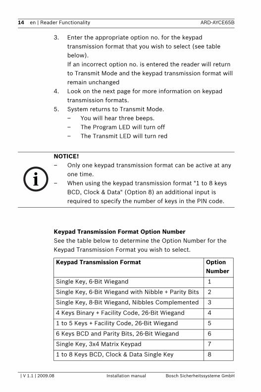
3. Enter the appropriate option no. for the keypad transmission format that you wish to select (see table below).If an incorrect option no. is entered the reader will return to Transmit Mode and the keypad transmission format will remain unchanged
4. Look on the next page for more information on keypad transmission formats.
5. System returns to Transmit Mode.– You will hear three beeps.– The Program LED will turn off– The Transmit LED will turn red
Keypad Transmission Format Option NumberSee the table below to determine the Option Number for the Keypad Transmission Format you wish to select.
NOTICE! – Only one keypad transmission format can be active at any
one time.– When using the keypad transmission format "1 to 8 keys
BCD, Clock & Data" (Option 8) an additional input is required to specify the number of keys in the PIN code.
Keypad Transmission Format Option Number
Single Key, 6-Bit Wiegand 1
Single Key, 6-Bit Wiegand with Nibble + Parity Bits 2
Single Key, 8-Bit Wiegand, Nibbles Complemented 3
4 Keys Binary + Facility Code, 26-Bit Wiegand 4
1 to 5 Keys + Facility Code, 26-Bit Wiegand 5
6 Keys BCD and Parity Bits, 26-Bit Wiegand 6
Single Key, 3x4 Matrix Keypad 7
1 to 8 Keys BCD, Clock & Data Single Key 8

ARD-AYCE65B Reader Functionality | en 15
Bosch Sicherheitssysteme GmbH Installation manual | V 1.1 | 2009.08
* Option No. 1 is the default factory setting.More information on each of the different keypad transmission formats is available below and on the following pages.
5.3.1 Option No. 1: Single Key, 6-Bit Wiegand Each key press immediately sends 4 bits with 2 parity bits added.Even parity for the first 3 bits and odd parity for the last 3 bits.
* = Hexadecimal
5.3.2 Option No. 2: Single Key, 6-Bit Wiegand Nibble and ParitiesEach key press immediately sends 4 bits with 2 parity bits added.Even parity for the first 3 bits and odd parity for the last 3 bits.
* = Hexadecimal
0 = 110100 = "A" * 6 = 101100
1 = 000010 7 = 101111
2 = 000100 8 = 110001
3 = 000111 9 = 110010
4 = 101001 ? = 110111 ="B" *
5 = 101010 # = 011001 ="C" *
0 = 000001 6 = 101100
1 = 000010 7 = 101111
2 = 000100 8 = 110001
3 = 000111 9 = 110010
4 = 101001 ? = 110100 ="A" *
5 = 101010 # = 110111 ="B" *

16 en | Reader Functionality ARD-AYCE65B
| V 1.1 | 2009.08 Installation manual Bosch Sicherheitssysteme GmbH
5.3.3 Option No. 3: Single Key, 8-Bit Wiegand Nibbles ComplementedInverts the most significant bits in the message leaving the least 4 significant bits as Binary-Coded Decimal (BCD) representation of the key. The host system receives an 8-bit message.
* = Hexadecimal
5.3.4 Option No. 4: 4 Keys Binary + Facility Code, 26-Bit WiegandBuffers 4 keys and outputs keypad data with a three digit facility code like a standard 26-Bit card output.The facility code is set in Programming Menu number four and can be in the range 000 to 255. The factory default setting for the facility code is 000. (See changing the Facility Code on page 22 for more information.)The keypad PIN code is 4-digit long and can range between 0000 and 9999. On the fourth key press of the 4 digit PIN code, the data is sent across the Wiegand Data lines as binary data in the same format as a 26-Bit Card.If the ? key or the # key are pressed during PIN code entry, the keypad will clear the PIN code entry buffer, generate a beep and is ready to receive a new 4 digit keypad PIN code. If the entry of the 4 digits keypad PIN code is disrupted and no number key is pressed within 5 seconds, the keypad will clear the PIN code entry buffer, generate a beep and is ready to receive a new 4 digits keypad PIN code.
(EP) FFFF FFFF AAAA AAAA AAAA AAAA (OP)
0 = 11110000 6 = 10010110
1 = 11100001 7 = 10000111
2 = 11010010 8 = 01111000
3 = 11000011 9 = 01101001
4 = 10110100 ? = 01011010 ="A" *
5 = 10100101 # = 01001011 ="B" *
ARD-AYCE65B Reader Functionality | en 17
Bosch Sicherheitssysteme GmbH Installation manual | V 1.1 | 2009.08
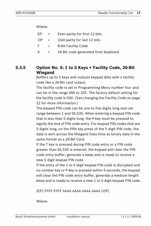
Where:
5.3.5 Option No. 5: 1 to 5 Keys + Facility Code, 26-Bit WiegandBuffers up to 5 keys and outputs keypad data with a facility code like a 26-Bit card output.The facility code is set in Programming Menu number four and can be in the range 000 to 255. The factory default setting for the facility code is 000. (See changing the Facility Code on page 22 for more information.)The keypad PIN code can be one to five digits long and can range between 1 and 65,535. When entering a keypad PIN code that is less than 5 digits long, the # key must be pressed to signify the end of PIN code entry. For keypad PIN codes that are 5 digits long, on the fifth key press of the 5 digit PIN code, the data is sent across the Wiegand Data lines as binary data in the same format as a 26-Bit Card.If the ? key is pressed during PIN code entry or a PIN code greater than 65,535 is entered, the keypad will clear the PIN code entry buffer, generate a beep and is ready to receive a new 5 digit keypad PIN code.If the entry of the 1 to 5 digit keypad PIN code is disrupted and no number key or # key is pressed within 5 seconds, the keypad will clear the PIN code entry buffer, generate a medium length beep and is ready to receive a new 1 to 5 digit keypad PIN code.
(EP) FFFF FFFF AAAA AAAA AAAA AAAA (OP)
Where:
EP = Even parity for first 12 bits
OP = Odd parity for last 12 bits
F = 8-Bit Facility Code
A = 16-Bit code generated from keyboard
18 en | Reader Functionality ARD-AYCE65B
| V 1.1 | 2009.08 Installation manual Bosch Sicherheitssysteme GmbH
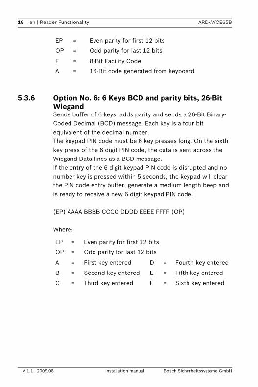
5.3.6 Option No. 6: 6 Keys BCD and parity bits, 26-Bit WiegandSends buffer of 6 keys, adds parity and sends a 26-Bit Binary-Coded Decimal (BCD) message. Each key is a four bit equivalent of the decimal number.The keypad PIN code must be 6 key presses long. On the sixth key press of the 6 digit PIN code, the data is sent across the Wiegand Data lines as a BCD message.If the entry of the 6 digit keypad PIN code is disrupted and no number key is pressed within 5 seconds, the keypad will clear the PIN code entry buffer, generate a medium length beep and is ready to receive a new 6 digit keypad PIN code.
(EP) AAAA BBBB CCCC DDDD EEEE FFFF (OP)
Where:
EP = Even parity for first 12 bits
OP = Odd parity for last 12 bits
F = 8-Bit Facility Code
A = 16-Bit code generated from keyboard
EP = Even parity for first 12 bits
OP = Odd parity for last 12 bits
A = First key entered D = Fourth key entered
B = Second key entered E = Fifth key entered
C = Third key entered F = Sixth key entered

ARD-AYCE65B Reader Functionality | en 19
Bosch Sicherheitssysteme GmbH Installation manual | V 1.1 | 2009.08
5.3.7 Option No. 7: Single Key, 3x4 Matrix Keypad (ARD-MDP64)This unique mode is intended to let the host controller scan the ARD-AYCE65B keypad while still keeping the proximity card readers 26-Bit Wiegand or Clock & Data formats active.An optional interface board must be used between the ARD-AYCE65B and the host system. Each key press is immediately sent on DATA0 as an ASCII character at a baud rate of 9600 bits per second.When a key is pressed DATA1 is pulled "low" until the key is released at which point DATA1 will be set to "high". This allows the controller to detect the duration of the key press.The ARD-MDP64 interface unit outputs the data received to 7 outputs emulating a keyboard. The interface unit will not affect any data that it receives from the proximity reader whether it is 26-Bit Wiegand or Clock & Data.Key pressed = ASCII Value
5.3.8 Option No. 8: 1 to 8 Keys BCD, Clock & DataBuffers up to 8 keys and outputs keypad data without a facility code like standard Clock and Data card output.The keypad PIN code can be one to eight digits long. The PIN code length is selected while programming the reader for Option 8. The reader will transmit the data when it receives the last key press of the PIN code. The data is sent across the two data output lines as binary data in Clock & Data format. If the ? key or the # key are pressed during PIN code entry, the keypad will clear the PIN code entry buffer, generate a beep and is ready to receive a new keypad PIN code.
0 = '0' ( 0x30 hex ) 6 = '6' ( 0x36 hex )
1 = '1' ( 0x31 hex ) 7 = '7' ( 0x37 hex )
2 = '2' ( 0x32 hex ) 8 = '8' ( 0x38 hex )
3 = '3' ( 0x33 hex ) 9 = '9' ( 0x39 hex )
4 = '4' ( 0x34 hex ) ? = '*' ( 0x2A hex )
5 = '5' ( 0x35 hex ) # = '#' ( 0x23 hex )
20 en | Reader Functionality ARD-AYCE65B
| V 1.1 | 2009.08 Installation manual Bosch Sicherheitssysteme GmbH
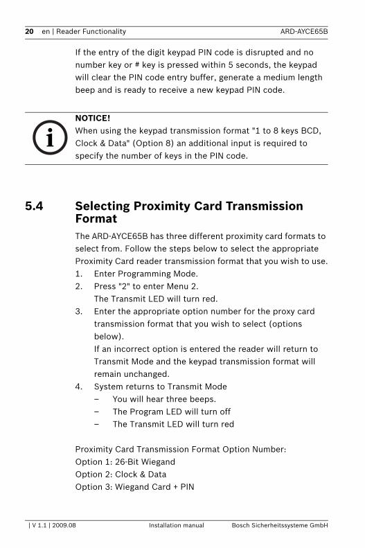
If the entry of the digit keypad PIN code is disrupted and no number key or # key is pressed within 5 seconds, the keypad will clear the PIN code entry buffer, generate a medium length beep and is ready to receive a new keypad PIN code.
5.4 Selecting Proximity Card Transmission FormatThe ARD-AYCE65B has three different proximity card formats to select from. Follow the steps below to select the appropriate Proximity Card reader transmission format that you wish to use.1. Enter Programming Mode. 2. Press "2" to enter Menu 2.
The Transmit LED will turn red.3. Enter the appropriate option number for the proxy card
transmission format that you wish to select (options below).If an incorrect option is entered the reader will return to Transmit Mode and the keypad transmission format will remain unchanged.
4. System returns to Transmit Mode– You will hear three beeps.– The Program LED will turn off– The Transmit LED will turn red
Proximity Card Transmission Format Option Number: Option 1: 26-Bit WiegandOption 2: Clock & DataOption 3: Wiegand Card + PIN
NOTICE! When using the keypad transmission format "1 to 8 keys BCD, Clock & Data" (Option 8) an additional input is required to specify the number of keys in the PIN code.
ARD-AYCE65B Reader Functionality | en 21
Bosch Sicherheitssysteme GmbH Installation manual | V 1.1 | 2009.08
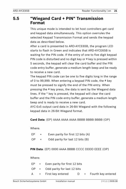
5.5 "Wiegand Card + PIN" Transmission FormatThis unique mode is intended to let host controllers get card and keypad data simultaneously. This option overrules the selected Keypad Transmission Format and sends the keypad data as described below.After a card is presented to ARD-AYCE65B, the program LED starts to flash in Green and indicates that ARD-AYCE65B is waiting for the PIN code. If the entry of one to five digit keypad PIN code is disturbed and no digit key or # key is pressed within 5 seconds, the keypad will clear the card buffer and the PIN code entry buffer, generate a medium length beep and be ready to receive a new card.The keypad PIN code can be one to five digits long in the range of 0 to 99,999. When entering a keypad PIN code, the # key must be pressed to signify the end of the PIN entry. When pressing the # key press, the data is sent by the Wiegand data lines. If the * key is pressed, the keypad will clear the card buffer and the PIN code entry buffer, generate a medium length beep and is ready to receive a new card.AYC-Ex5 output card data in 26-Bit Wiegand with the following keypad data in 26-Bit Wiegand format.
Card Data: (EP) AAAA AAAA AAAA BBBB BBBB BBBB (OP)
Where:
PIN Data: (EP) 0000 AAAA BBBB CCCC DDDD EEEE (OP)
Where:
EP = Even parity for first 12 bits (A)
OP = Odd parity for last 12 bits (B)
EP = Even parity for first 12 bits
OP = Odd parity for last 12 bits
A = First key entered D = Fourth key entered

22 en | Reader Functionality ARD-AYCE65B
| V 1.1 | 2009.08 Installation manual Bosch Sicherheitssysteme GmbH
If the PIN code is less than 5 digits, all the most significant nibbles are filled with 0.
Example: (EP) 0000 0000 0000 0000 AAAA BBBB (OP)
Where:
5.6 Changing the Programming Code1. Enter Programming Mode. 2. Press "3" to enter Menu 3.
The Transmit LED will turn red.3. Enter the new 4 digit code you wish to set as the
Programming Code 4. System returns to Transmit Mode
– You will hear three beeps– The Program LED will turn off– The Transmit LED will turn red
B = Second key entered E = Fifth key entered
C = Third key entered
EP = Even parity for first 12 bits
OP = Odd parity for last 12 bits
A = First key entered
B = Second key entered
NOTICE! – Programming Code can not be erased, i.e. the code 0000 is
invalid and will not erase the Programming Code.– The factory default 4-digit Programming Code is 1234.

ARD-AYCE65B Reader Functionality | en 23
Bosch Sicherheitssysteme GmbH Installation manual | V 1.1 | 2009.08
5.7 Changing the Facility Code1. Enter Programming Mode. 2. Press "4" to enter Menu 4.
The Transmit LED will turn red.3. Enter the new 3-digit code you wish to set as the Facility
Code 4. System returns to Transmit Mode
– You will hear three beeps– The Program LED will turn off– The Transmit LED will turn red
5.8 Setting the Backlight1. Enter Programming Mode2. Press "6" to enter menu 6
The Transmit LED will turn red3. Enter the appropriate option number for the backlight
option that you wish to select "0" for always off"1" for always on"2" for 10 sec. backlight after a key is pressed otherwise off"3" for 10 sec. backlight after a key is pressed otherwise dimmed
4. System returns to Transmit Mode – You will hear three beeps– The Transmit LED will turn red.
NOTICE! – Facility Code can be in the range of 000 to 255. – The default Facility Code is 0.

24 en | Reader Functionality ARD-AYCE65B
| V 1.1 | 2009.08 Installation manual Bosch Sicherheitssysteme GmbH
5.9 Return to Factory Default Settings
1. Enter Programming Mode. 2. Press "0" to enter Menu 0.
The Transmit LED will Flash red.The Program LED will flash red.
3. Enter your 4 digit programming code– If the Programming Code is valid, all memory will be
erased, you will hear three beeps and the controller will return to Normal Mode
– If the Programming Code is invalid you will hear a long beep and the controller will return to Normal Mode without erasing the memory of the controller
5.10 Replacing a Lost Programming CodeIn the event that the Programming Code is forgotten, the ARD-AYCE65B may be reprogrammed in the field using the following instructions:1. Remove power from the reader.2. Activate tamper by removing the reader from the wall or
removing the reader's case.3. Apply power to the reader.4. You now have 10 seconds to enter Programming Mode
using the factory default Programming Code 1234.
CAUTION! You must be very careful before using this command! This will erase the entire memory and return all codes to their factory default setting.

ARD-AYCE65B Appendix | en 25
Bosch Sicherheitssysteme GmbH Installation manual | V 1.1 | 2009.08
6 Appendix
6.1 LED displays
Reader mode/action Mode/Transmit LED(left hand side)
Door/Program LED(right hand side)
Transmit mode (red)
Transmitting card or PIN data
(flash green)
Entering programming mode
1. Press 4 times the # key2. Enter the 4 digit programming code
(red)
(green)
Exiting programming mode
Press # (red) and a beep
Selecting keypad transmission format
1. Enter programming mode
2. Press 13. Enter the no. for the keypad transmission format.4. Back to transmit mode
(red)
(red)
(green)
(green)
and three beeps
Selecting Proximity Card transmission format
1. Enter programming mode
2. Press 23. Enter the no. for the prxy card transmission format.4. Back to transmit mode.
(red)
(red)
(green)
(green)
and three beeps
Changing the Programming code

26 en | Appendix ARD-AYCE65B
| V 1.1 | 2009.08 Installation manual Bosch Sicherheitssysteme GmbH
1. Enter programming mode
2 Press 33. Enter the new 4 digit code4. Back to transmit mode
(red)
(red)
(green)
(green)
and three beeps
Changing the Facility code
1. Enter programming mode
2. Press 43. Enter the new 3 digit code4. Back to transmit mode
(red)
(red)
(green)
(green)
and three beeps
Setting the backlight
1. Enter programming mode
2. Press 63. Enter the no. for the backlight option4. Back to transmit mode
(red)
(red)
(green)
(green)
and three beeps
Return to Factory Default Settings
1. Enter programming mode
2. Press 03. Enter the 4 digit programming code4. Back to transmit mode
(flash red)
three beeps
(red)
(green)
(flash red)
Reader mode/action Mode/Transmit LED(left hand side)
Door/Program LED(right hand side)
ARD-AYCE65B Appendix | en 27
Bosch Sicherheitssysteme GmbH Installation manual | V 1.1 | 2009.08
6.2 Technical Support
Europe, Middle East, Africa:
America:
Asia Pacific:
Bosch Security Systems B.V.P.O. Box 800025600 JB Eindhoven, The NetherlandsPhone: +31(0)402783955Fax: +31(0)[email protected]://www.boschsecurity.com
Bosch Security Systems130 Perinton ParkwayFairport, New York, 14450, USAPhone: +1 585 223 4060Fax: +1 800 289 [email protected]://www.boschsecurity.us
Bosch Security Systems Pte Ltd.38C Jalan PemimpinSingapore 577180Phone: +65 6319 3450Fax: +65 6319 [email protected]://www.boschsecurity.com
28 en | Appendix ARD-AYCE65B
| V 1.1 | 2009.08 Installation manual Bosch Sicherheitssysteme GmbH


Bosch Sicherheitssysteme GmbHRobert-Koch-Straße 100D-85521 OttobrunnGermanyTelefon +49 89 6290-0Fax +49 89 6290-1020www.boschsecurity.com © Bosch Sicherheitssysteme GmbH, 2009


![ARD Tutorials[1]](https://img.pdfslide.us/doc/110x75/544be5adaf7959a4438b562e/ard-tutorials1.jpg)


![VC-7104-Operation_Manual c20030605 [202]](https://img.pdfslide.us/doc/110x75/55cf9946550346d0339c8ada/vc-7104-operationmanual-c20030605-202.jpg)