Embed Size (px)
Citation preview

Submersible Motor Pump
Amarex N
60 HzDN 2" - DN 4" [DN 50 - DN 100]
Type Series Booklet

Legal information/Copyright
Type Series Booklet Amarex N
All rights reserved. The contents provided herein must neither be distributed, copied, reproduced,edited or processed for any other purpose, nor otherwise transmitted, published or made available to athird party without the manufacturer's express written consent.
Subject to technical modification without prior notice.
© KSB Aktiengesellschaft, Frankenthal 1/24/2017

Contents
Waste Water...................................................................................................................................................... 4Submersible Motor Pump.......................................................................................................................................................... 4
Amarex N.............................................................................................................................................................................. 4Main applications........................................................................................................................................................... 4Fluids handled ................................................................................................................................................................ 4Operating data............................................................................................................................................................... 4Designation .................................................................................................................................................................... 4Design details ................................................................................................................................................................. 4Materials ......................................................................................................................................................................... 5Product benefits ............................................................................................................................................................. 5Overview of product features / selection tables .......................................................................................................... 6Technical data .............................................................................................................................................................. 10Characteristic curves..................................................................................................................................................... 16Types of installation..................................................................................................................................................... 24Installation information............................................................................................................................................... 24Dimensions ................................................................................................................................................................... 26Scope of supply ............................................................................................................................................................ 34Accessories .................................................................................................................................................................... 34
Contents
3

Waste WaterSubmersible Motor Pump
4 Amarex N
Waste Water
Submersible Motor Pump
Amarex N
Main applications▪ Waste water management
▪ Drainage systems
▪ Waste water treatment plants
▪ Sludge disposal
▪ Drainage of rooms and areas at risk of flooding onmunicipal, industrial and commercial premises
Fluids handled▪ Service water
▪ Gray water
▪ Sewage containing feces
▪ Waste water containing long fibers and solid substances
▪ Fluids containing gas
▪ Activated sludge
▪ Digested sludge
▪ Raw sludge
Operating data
Operating properties
Characteristic ValueFlow rate Q [US.gpm] ≤ 660
Q [m3/h] ≤ 150Head H [ft] ≤ 154
H [m] ≤ 47Fluid temperature T [°F] ≤ 1041)
T [°C] ≤ 401)
Motor rating P2 [hp] 1,1 - 5
Designation
Example: Amarex N F 80-220 / 04 4 YL G-180
Designation key
Code DescriptionAmarex N Type seriesF Impeller type
F Free-flow impellerS Cutter
80-220 Hydraulic size04 Motor size4 Number of motor poles
2 2-pole4 4-pole
YL Motor version
YL2) Explosion-proof, for fluidtemperatures of up to 104 °F [40 °C]
WL Not explosion-proof, for fluidtemperatures of up to 140 °F [60 °C]
G Material variantG Pump casing: gray cast iron A48 Class
40BIntermediate casing: gray cast ironA48 Class 40BImpeller: gray cast iron A48 Class 40B
G1 Pump casing: gray cast iron A48 Class40BIntermediate casing: gray cast ironA48 Class 40BImpeller: Noridur (duplex stainlesssteel) A743 CD4 MCU
G2 Pump casing: gray cast iron A48 Class40BIntermediate casing: gray cast ironA48 Class 35BImpeller: Norihard (white cast iron)A532 II C15% CrMo-Hc
GH Pump casing: gray cast iron A48 Class40BIntermediate casing: Norihard (whitecast iron) A532 II C15% CrMo-HcImpeller: Norihard (white cast iron)A532 II C15% CrMo-Hc
180 Nominal impeller diameter [mm]
Design details
Design▪ Fully floodable submersible motor pump
▪ Not self-priming
▪ Close-coupled design
Drive▪ Three-phase asynchronous squirrel-cage motor
▪ Version with explosion protection to NEC 500: Explosion-proof for Class I, Division 1, Groups C and D, T4, hazardous(classified) locations.
Shaft seal▪ Two bi-directional mechanical seals in tandem
arrangement, with liquid reservoir
1) For short periods (3 to 5 min or until the temperature sensors trip) the WL model can be operated up to 176 °F [80 °C].2) In countries stipulating explosion-proof units for handling sewage with feces, motor version YL must be used.

Waste WaterSubmersible Motor Pump
5Amarex N
Impeller type▪ Various application-oriented impeller types (⇨ Page 7)
Bearings▪ Grease-packed bearings sealed for life
▪ Maintenance-free
Materials
Overview for material variant G
Component S impeller F impellerAmarex N S 50-170/...Amarex N S 50-220/...
Amarex N F 50-220Amarex N F 65-170Amarex N F 65-220Amarex N F 80-220Amarex N F 100-220
G GCasing A48 Class 40B A48 Class 40BIntermediate casing A48 Class 40B A48 Class 40BImpeller A48 Class 40B A48 Class 40BCutter D3 (X210 Cr12)3) -
Shaft A 276 Type 420 A 276 Type 420Mechanical seal Drive end Carbon/Al2O3 Carbon/Al2O3
Pump end SiC/SiC SiC/SiCScrews/bolts A 276 Type 304 A 276 Type 304Elastomer seals NBR NBR
Overview for material variants G1, G2, GH
Component F impellerAmarex N F 50-220Amarex N F 65-170Amarex N F 65-220Amarex N F 80-220Amarex N F 100-220
G1 G2 GHCasing A48 Class 40B A48 Class 40B A48 Class 40BIntermediate casing A48 Class 40B A48 Class 40B A532 II C15% CrMo-HcImpeller A743 CD4 MCU4) A532 II C15% CrMo-Hc5) A532 II C15% CrMo-Hc5)
Shaft A 276 Type 420 A 276 Type 420 A 276 Type 420Mechanical seal Drive end Carbon/Al2O3 Carbon/Al2O3 Carbon/Al2O3
Pump end SiC/SiC SiC/SiC SiC/SiCScrews/bolts A 276 Type 304 A 276 Type 304 A 276 Type 304Elastomer seals NBR6) NBR6) NBR6)
Product benefits▪ Easy and fast to connect with polarized, absolutely water-
tight cable entry and KSB plug-type connection for correctinstallation
▪ Motor tightly sealed by an absolutely watertight cableentry with individually stripped, tinned and resin-sealedconductors offering multiple protection even in the eventof damage to the cable sheath and insulation
▪ Maximum operating reliability thanks to optimum motorrating for duty cycle S1, thermal class F, explosion-proofversion in FM/CSA Explosion-proof Class I, Division 1,Groups C & D, T4
▪ Long service life with shaft made of corrosion-resistantstainless steel
▪ Maintenance-free, ideal continuous-duty pumps withlong-life bearings sealed on both sides, lubricated for life
▪ Environmentally friendly, non-toxic, food-approved oil fillfor mechanical seal lubrication (liquid reservoir)
▪ Marked reduction of energy costs by optimized hydraulicsystem and high efficiency
▪ Absolutely reliable and non-clogging thanks to optimizedcutter (S impeller)
▪ Close-coupled pump design prevents risk of leakage(pump volute casing and motor housing cast in one singlepiece)
▪ Easy installation and removal of pumps for stationaryinstallation with automatic, bolt-free connection; leakageprevented by flexible sealing elements
▪ Easy to service: Wetted hexagon socked head cap screwsmade of stainless steel are easy to remove, even afteryears of operation.
▪ Two bi-directional mechanical seals with oil chamber filledwith ecologically acceptable oil provide double safety
▪ Installation of a mechanical seal with covered spring forabrasive and aggressive fluids possible without anyproblems
3) High-alloy tool steel4) Noridur (duplex stainless steel)5) Norihard (white cast iron)6) Optional: FPM

Waste WaterSubmersible Motor Pump
6 Amarex N
▪ One spare parts set fits all sizes thanks to modular designsystem.
Overview of product features / selection tables
Product overview
Material variant G
Size S impeller F impellerAmarex N S 50-... Amarex N F 50-...
Amarex N F 65-...Amarex N F 80-...Amarex N F 100-...
Number of motor poles2-pole 50-170/...
50-220/...50-170/...50-220/...65-170/...
4-pole - 65-220/...80-220/...100-220/...
Explosion protection
Motor version YL7) or Explosion-proof Class I, Division 1, Groups C & DMotor version WL Not explosion-proof
Motor8)
Starting method DOL9)
Electrical voltage 208 V10), 230 V10), 380 V10), 460 V10), 575 V11)
Cooling Cooled by surrounding fluidDuty cycle S1 – submerged (max. 85 ft [25 m]) (see 2) in outline drawing)
S3 – outside the fluid (see 1) and RS in the outline drawing))
Power cable12)
Type Rubber-sheathed cable AWG 15-8 (8 x 1.5 mm2)Length Canada: 30 ft [10 m], USA: 50 ft [15 m]Cable entry Absolutely watertightSealing elementsShaft seal Mechanical sealElastomer seals NBRMonitoring equipmentWinding temperature version YL Temperature monitoring circuit (with automatic reset and start-up) and limiting
circuit (temperature limit for explosion protection without automatic reset):bimetal switch to be connected directly to a KSB PumpSafe Relay or a similar
device.Winding temperature version WL Temperature monitoring circuit (with automatic reset and start-up): bimetal
switch to be connected directly to a KSB PumpSafe Relay or a similar device.Leakage sensor Leakage sensor in the motor space13)
Coating Environmentally friendly KSB top coat (two-component epoxy paint), colorRAL 5002, film thickness = 3.15 mils [80 µm]
Installation (⇨ Page 24)
Maximum fluid temperatureMotor version YL 104 °F [40 °C]Motor version WL 140 °F [60 °C]
7) In countries stipulating explosion-proof units for handling sewage with feces, use motor version YL.8) All motors have a service factor of 1.15. All motors are suitable for frequency inverter operation. Rated supply voltage +/-
10 % to NEMA standards.9) Maximum switching frequency: 30 starts per hour10) FM approved11) CSA12) Class F insulation system. Cables selected to NEC standards.13) 8-core power cable required

Waste WaterSubmersible Motor Pump
7Amarex N
Material variants G, G1, G2 and GH
Size S impeller F impellerAmarex N S 50-170/...Amarex N S 50-220/...
Amarex N F 50-...Amarex N F 65-...Amarex N F 80-...Amarex N F 100-...
Material variant G G1 G2 GHNumber of motor poles2-pole - 50-170/...
50-220/...65-170/...
4-pole - 65-220/...80-220/...100-220/...
Suction flangeDrilled to ASME 150 lb (ANSI B16.5) - ✘Sealing elementsElastomer seals: O-rings and gaskets made ofViton, lower mechanical seal with Viton jointrings
✘ ✘
Shaft seal: special mechanical seal(mechanical seal with covered spring –HJ977)14)
✘ ✘
Power cablesStandard rubber-sheathed cable AWG 15-8(S1BN8-F 8G1.5); for pumps with leakagesensor; for version YLG, WLG15)
✘ ✘
Shielded rubber-sheathed cable AWG 15-8(S07RC4N8-F 8G1.5)16) for a pump with orwithout leakage sensor, for versions YLG andWLG operated on a frequency inverter17)
✘ ✘
Coating Environmentally friendly KSB standard coating (two-component epoxy paint),color RAL 5002, film thickness = 11.81 mils [300 µm]
Installation (⇨ Page 24)
Impellers
Free-flow impeller (impeller type F)
Suitable for the following fluids:
fluids containing solids and stringy material as well as fluids with entrappedair or entrapped gas
F impellers are suitable for handling the following fluids:
▪ Activated sludge
▪ Digested sludge
▪ Heating sludge
▪ Mixed water
▪ Raw waste water
▪ Raw sludge
▪ Recirculated sludge
14) Seal faces made of silicon carbide/silicon carbide, sealing elements made of Viton, springs and metal parts made of stainlesssteel, O-rings and gaskets made of Viton (FPM)
15) Available total lengths 50 ft [15 m]/65 ft [20 m]/98 ft [30 m]/ 130 ft [40 m]/164 ft [50 m]16) Available total lengths 30 ft [10 m]/50 ft [15 m]/65 ft [20 m]/98 ft [30 m]/ 130 ft [40 m]/164 ft [50 m]17) The percentage of submersible motor pumps operated on frequency inverters is on the increase. If pump set is operated on
a frequency inverter, high frequency interference signals occur in the area of the motor power cables. The electric cablesbetween the motor and frequency inverter can act like a transmitting antenna. In accordance with European Directive2014/30/EU these electromagnetic interferences must be limited. The frequency inverter must therefore be equipped with asuitable output filter and/or the electric cables between frequency inverter and motor have to be shielded. Therefore theuse of shielded electric cables is often demanded for submersible motor pumps operated on frequency inverters.

Waste WaterSubmersible Motor Pump
8 Amarex N
Impeller with cutter (impeller type S)
Suitable for the following fluids:
feces, domestic sewage and waste water containing long fibers
S impellers are suitable for handling the following fluids:
▪ Domestic waste water
▪ Gray water
▪ Sewage containing feces
Table of fluids handledThe table below for your guidance is based on KSB's long-standing experience. The data are standard values and are not to beconsidered as generally binding recommendations. More detailed advice is available from our specialist department. Make use ofour laboratory's expertise when selecting materials.
Selection aid for materials and hydraulic systems per fluid
Fluid handled18)
Rec
om
men
ded
mat
eria
l
Rec
om
men
ded
imp
elle
rty
pe19
)Comments, further recommendations
Gray water A48 Class 40B F, S Free passage > any solids contained, possibly pre-screened
River water A48 Class 40B F Free passage > any solids contained, possibly pre-screened
Contaminated surface water A48 Class 40B F Free passage > any solids contained, possibly pre-screened
Waste water
▪ Untreated municipal wastewater
A48 Class 40B F, S ATV20) recommends a free passage of 4" [100 mm], min. freepassage of 3" [76 mm]
▪ Waste water containing air orgas
A48 Class 40B F Up to 8 %, contact KSB for fluids with high outgassing rates
▪ Raw waste water A48 Class 40B F ATV20) recommends a free passage of 4" [100 mm], min. freepassage of 3" [76 mm]
▪ Mixed water A48 Class 40B F Free passage > any solids contained, possibly pre-screened
▪ Waste water or gray watercontaining long fibers
A48 Class 40B F, S Free passage > any solids contained, possibly pre-screened
▪ Highly abrasive waste watercausing wear (chemicallyneutral)
Norihard (whitecast iron): A532II C15 % CrMo-
Hc
F For a solids content < 5 g/l:G2, GH variant
▪ Corrosive waste water Noridur (duplexstainless steel):A743 CD4 MCU
F G1 variant, depending on fluid analysis
Sludge
▪ Raw sludge A48 Class 40B F Pumpable up to a dry substance content of: 8 % (F)
▪ Digested sludge A48 Class 40B F Pumpable up to a dry substance content of: 8 % (F)
▪ Activated sludge A48 Class 40B F Pumpable up to a dry substance content of: 8 % (F)
Industrial waste water containing ...
▪ Paint suspensions A48 Class 40B F Solvent-free, observe the operator's instructions.
▪ Lacquer/paint/varnishsuspensions
A48 Class 40B F Solvent-free, contact KSB to handle silicone-free fluids.
▪ Fibers/pulp A48 Class 40B F, S
▪ Chips/swarf Norihard (whitecast iron): A532II C15 % CrMo-
Hc
F G2 or GH variant, special mechanical seal, solids content < 5 g/l
19) The first impeller type listed should be given preference.18) For any fluids which are not listed in this table contact KSB.20) ATV = German regulatory body for waste water management
Waste WaterSubmersible Motor Pump
9Amarex N
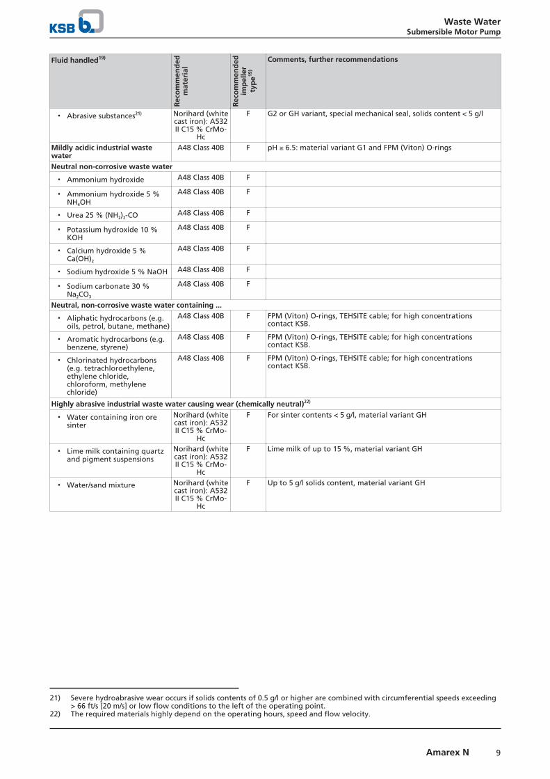
Fluid handled19)
Rec
om
men
ded
mat
eria
l
Rec
om
men
ded
imp
elle
rty
pe19
)
Comments, further recommendations
▪ Abrasive substances21) Norihard (whitecast iron): A532II C15 % CrMo-
Hc
F G2 or GH variant, special mechanical seal, solids content < 5 g/l
Mildly acidic industrial wastewater
A48 Class 40B F pH ≥ 6.5: material variant G1 and FPM (Viton) O-rings
Neutral non-corrosive waste water
▪ Ammonium hydroxide A48 Class 40B F
▪ Ammonium hydroxide 5 %NH4OH
A48 Class 40B F
▪ Urea 25 % (NH2)2-CO A48 Class 40B F
▪ Potassium hydroxide 10 %KOH
A48 Class 40B F
▪ Calcium hydroxide 5 %Ca(OH)2
A48 Class 40B F
▪ Sodium hydroxide 5 % NaOH A48 Class 40B F
▪ Sodium carbonate 30 %Na2CO3
A48 Class 40B F
Neutral, non-corrosive waste water containing ...
▪ Aliphatic hydrocarbons (e.g.oils, petrol, butane, methane)
A48 Class 40B F FPM (Viton) O-rings, TEHSITE cable; for high concentrationscontact KSB.
▪ Aromatic hydrocarbons (e.g.benzene, styrene)
A48 Class 40B F FPM (Viton) O-rings, TEHSITE cable; for high concentrationscontact KSB.
▪ Chlorinated hydrocarbons(e.g. tetrachloroethylene,ethylene chloride,chloroform, methylenechloride)
A48 Class 40B F FPM (Viton) O-rings, TEHSITE cable; for high concentrationscontact KSB.
Highly abrasive industrial waste water causing wear (chemically neutral)22)
▪ Water containing iron oresinter
Norihard (whitecast iron): A532II C15 % CrMo-
Hc
F For sinter contents < 5 g/l, material variant GH
▪ Lime milk containing quartzand pigment suspensions
Norihard (whitecast iron): A532II C15 % CrMo-
Hc
F Lime milk of up to 15 %, material variant GH
▪ Water/sand mixture Norihard (whitecast iron): A532II C15 % CrMo-
Hc
F Up to 5 g/l solids content, material variant GH
21) Severe hydroabrasive wear occurs if solids contents of 0.5 g/l or higher are combined with circumferential speeds exceeding> 66 ft/s [20 m/s] or low flow conditions to the left of the operating point.
22) The required materials highly depend on the operating hours, speed and flow velocity.

Waste WaterSubmersible Motor Pump
10 Amarex N
Technical data
Technical data 3~ 575 V, material variant G
Size Impeller diameter Motor version P1 PN IN IA T23) [lbs] Mat. No.
[hp] [hp] [A] [A] [°F]S 50-170/012 100 YL 3,6 2,55 3,6 25 104 86 -S 50-170/012 100 WL 3,6 2,55 3,6 25 140 86 -S 50-170/012 110 YL 3,6 2,55 3,6 25 104 86 -S 50-170/012 110 WL 3,6 2,55 3,6 25 140 86 -
S 50-170/022 120 YL 4,3 3,10 4,0 25 104 86 -S 50-170/022 120 WL 4,3 3,10 4,0 25 140 86 -S 50-170/022 130 YL 4,3 3,10 4,0 25 104 86 -S 50-170/022 130 WL 4,3 3,10 4,0 25 140 86 -
S 50-220/042 130 YL 6,4 5,00 5,5 72 104 119 -S 50-220/042 130 WL 6,4 5,00 5,5 72 140 119 -S 50-220/042 140 YL 6,4 5,00 5,5 72 104 119 -S 50-220/042 140 WL 6,4 5,00 5,5 72 140 119 -S 50-220/042 150 YL 6,4 5,00 5,5 72 104 119 -S 50-220/042 150 WL 6,4 5,00 5,5 72 140 119 -S 50-220/042 158 YL 6,4 5,00 5,5 72 104 119 -S 50-220/042 158 WL 6,4 5,00 5,5 72 140 119 -
F 50-170/002 90 YL 2,6 1,70 2,9 25 104 90 -F 50-170/002 90 WL 2,6 1,70 2,9 25 140 90 -
F 50-170/022 107 YL 4,3 3,10 4,0 25 104 90 -F 50-170/022 107 WL 4,3 3,10 4,0 25 140 90 -
F 50-220/032 110 YL 4,7 3,70 4,4 72 104 112 -F 50-220/032 110 WL 4,7 3,70 4,4 72 140 112 -
F 50-220/042 120 YL 6,4 5,00 5,5 72 104 112 -F 50-220/042 120 WL 6,4 5,00 5,5 72 140 112 -F 50-220/042 130 YL 6,4 5,00 5,5 72 104 114 -F 50-220/042 130 WL 6,4 5,00 5,5 72 140 114 -F 50-220/042 140 YL 6,4 5,00 5,5 72 104 114 -F 50-220/042 140 WL 6,4 5,00 5,5 72 140 114 -
F 65-170/032 112 YL 4,7 3,70 4,4 72 104 128 -F 65-170/032 112 WL 4,7 3,70 4,4 72 140 128 -
F 65-170/042 120 YL 6,4 5,00 5,5 72 104 128 -F 65-170/042 120 WL 6,4 5,00 5,5 72 140 128 -F 65-170/042 128 YL 6,4 5,00 5,5 72 104 128 -F 65-170/042 128 WL 6,4 5,00 5,5 72 140 128 -
F 65-220/004 135 YL 1,9 1,10 2,5 16 104 108 -F 65-220/004 135 WL 1,9 1,10 2,5 16 140 108 -
F 65-220/014 145 YL 2,7 1,70 2,8 16 104 108 -F 65-220/014 145 WL 2,7 1,70 2,8 16 140 108 -F 65-220/014 155 YL 2,7 1,70 2,8 16 104 108 -F 65-220/014 155 WL 2,7 1,70 2,8 16 140 108 -
F 65-220/024 165 YL 3,7 2,40 3,4 16 104 110 -F 65-220/024 165 WL 3,7 2,40 3,4 16 140 110 -F 65-220/024 175 YL 3,7 2,40 3,4 16 104 110 -F 65-220/024 175 WL 3,7 2,40 3,4 16 140 110 -
F 80-220/034 120 YL 4,1 3,00 4,3 38 104 139 -F 80-220/034 120 WL 4,1 3,00 4,3 38 140 139 -F 80-220/034 135 YL 4,1 3,00 4,3 38 104 139 -F 80-220/034 135 WL 4,1 3,00 4,3 38 140 139 -
F 80-220/044 150 YL 6,9 5,00 6,0 38 104 139 -F 80-220/044 150 WL 6,9 5,00 6,0 38 140 139 -F 80-220/044 165 YL 6,9 5,00 6,0 38 104 141 -F 80-220/044 165 WL 6,9 5,00 6,0 38 140 141 -F 80-220/044 180 YL 6,9 5,00 6,0 38 104 145 -F 80-220/044 180 WL 6,9 5,00 6,0 38 140 145 -
23) Fluid temperature

Waste WaterSubmersible Motor Pump
11Amarex N
Size Impeller diameter Motor version P1 PN IN IA T23) [lbs] Mat. No.
[hp] [hp] [A] [A] [°F]F 100-220/034 120 YL 4,1 3,00 4,3 38 104 139 -F 100-220/034 120 WL 4,1 3,00 4,3 38 140 139 -
F 100-220/044 135 YL 6,9 5,00 6,0 38 104 139 -F 100-220/044 135 WL 6,9 5,00 6,0 38 140 139 -F 100-220/044 150 YL 6,9 5,00 6,0 38 104 139 -F 100-220/044 150 WL 6,9 5,00 6,0 38 140 139 -F 100-220/044 165 YL 6,9 5,00 6,0 38 104 143 -F 100-220/044 165 WL 6,9 5,00 6,0 38 140 143 -F 100-220/044 180 YL 6,9 5,00 6,0 38 104 146 -F 100-220/044 180 WL 6,9 5,00 6,0 38 140 146 -
Technical data 3~ 460 V, material variant G
Size Impeller diameter Motor version P1 P2 IN IA T23) [lbs] Mat. No.
[hp] [hp] [A] [A] [°F]S 50-170/012 100 YL 3,7 2,55 4,2 33 104 86 39190447S 50-170/012 100 WL 3,7 2,55 4,2 33 140 86 -S 50-170/012 110 YL 3,7 2,55 4,2 33 104 86 39190449
S 50-170/012 110 WL 3,7 2,55 4,2 33 140 86 -S 50-170/022 120 YL 4,4 3,10 4,8 33 104 86 39190451S 50-170/022 120 WL 4,4 3,10 4,8 33 140 86 -S 50-170/022 130 YL 4,4 3,10 4,8 33 104 86 39190453
S 50-170/022 130 WL 4,4 3,10 4,8 33 140 86 -S 50-220/042 130 YL 6,9 5,00 7,6 55 104 119 39190455S 50-220/042 130 WL 6,9 5,00 7,6 55 140 119 -S 50-220/042 140 YL 6,9 5,00 7,6 55 104 119 39190457S 50-220/042 140 WL 6,9 5,00 7,6 55 140 119 -S 50-220/042 150 YL 6,9 5,00 7,6 55 104 119 39190459S 50-220/042 150 WL 6,9 5,00 7,6 55 140 119 -S 50-220/042 158 YL 6,9 5,00 7,6 55 104 119 39190461S 50-220/042 158 WL 6,9 5,00 7,6 55 140 119 -
F 50-170/002 90 YL 2,6 1,70 3,4 33 104 90 39190401F 50-170/002 90 WL 2,6 1,70 3,4 33 140 90 -
F 50-170/022 107 YL 4,4 3,10 4,8 33 104 90 39190403F 50-170/022 107 WL 4,4 3,10 4,8 33 140 90 -
F 50-220/032 110 YL 5,2 3,70 6,2 55 104 112 39190405F 50-220/032 110 WL 5,2 3,70 6,2 55 140 112 -
F 50-220/042 120 YL 6,9 5,00 7,6 55 104 112 39190407F 50-220/042 120 WL 6,9 5,00 7,6 55 140 112 -F 50-220/042 130 YL 6,9 5,00 7,6 55 104 114 39190409F 50-220/042 130 WL 6,9 5,00 7,6 55 140 114 -F 50-220/042 140 YL 6,9 5,00 7,6 55 104 114 39190411F 50-220/042 140 WL 6,9 5,00 7,6 55 140 114 -
F 65-170/032 112 YL 5,2 3,70 6,2 55 104 128 39190413F 65-170/032 112 WL 5,2 3,70 6,2 55 140 128 -
F 65-170/042 120 YL 6,9 5,00 7,6 55 104 128 39190415F 65-170/042 120 WL 6,9 5,00 7,6 55 140 128 -F 65-170/042 128 YL 6,9 5,00 7,6 55 104 128 39190417F 65-170/042 128 WL 6,9 5,00 7,6 55 140 128 -
F 65-220/004 135 YL 1,9 1,10 2,8 21 104 108 39190419F 65-220/004 135 WL 1,9 1,10 2,8 21 140 108 -
F 65-220/014 145 YL 2,7 1,70 3,3 21 104 108 39190421F 65-220/014 145 WL 2,7 1,70 3,3 21 140 108 -F 65-220/014 155 YL 2,7 1,70 3,3 21 104 108 39190423F 65-220/014 155 WL 2,7 1,70 3,3 21 140 108 -
F 65-220/024 165 YL 3,6 2,40 4,0 21 104 110 39190425F 65-220/024 165 WL 3,6 2,40 4,0 21 140 110 -F 65-220/024 175 YL 3,6 2,40 4,0 21 104 110 39190427F 65-220/024 175 WL 3,6 2,40 4,0 21 140 110 -
F 80-220/034 120 YL 4,1 3,00 5,9 49 104 139 39190429

Waste WaterSubmersible Motor Pump
12 Amarex N
Size Impeller diameter Motor version P1 P2 IN IA T23) [lbs] Mat. No.
[hp] [hp] [A] [A] [°F]F 80-220/034 120 WL 4,1 3,00 5,9 49 140 139 -F 80-220/034 135 YL 4,1 3,00 5,9 49 104 139 39190431F 80-220/034 135 WL 4,1 3,00 5,9 49 140 139 -
F 80-220/044 150 YL 6,9 5,00 8,0 49 104 139 39190433F 80-220/044 150 WL 6,9 5,00 8,0 49 140 139 -F 80-220/044 165 YL 6,9 5,00 8,0 49 104 141 39190435F 80-220/044 165 WL 6,9 5,00 8,0 49 140 141 -F 80-220/044 180 YL 6,9 5,00 8,0 49 104 145 39190437F 80-220/044 180 WL 6,9 5,00 8,0 49 140 145 -
F 100-220/034 120 YL 4,1 3,00 5,9 49 104 139 39190439F 100-220/034 120 WL 4,1 3,00 5,9 49 140 139 -
F 100-220/044 135 YL 6,9 5,00 8,0 49 104 139 39190441F 100-220/044 135 WL 6,9 5,00 8,0 49 140 139 -F 100-220/044 150 YL 6,9 5,00 8,0 49 104 139 39190443F 100-220/044 150 WL 6,9 5,00 8,0 49 140 139 -F 100-220/044 165 YL 6,9 5,00 8,0 49 104 143 39190445F 100-220/044 165 WL 6,9 5,00 8,0 49 140 143 -F 100-220/044 180 YL 6,9 5,00 8,0 49 104 146 39190483F 100-220/044 180 WL 6,9 5,00 8,0 49 140 146 -
Technical data 3~ 380 V, material variant G
Size Impeller diameter Motor version P1 P2 IN IA T23) [lbs] Mat. No.
[hp] [hp] [A] [A] [°F]S 50-170/012 100 YL 3,8 2,55 4,8 27 104 86 -S 50-170/012 100 WL 3,8 2,55 4,8 27 140 86 -S 50-170/012 110 YL 3,8 2,55 4,8 27 104 86 -S 50-170/012 110 WL 3,8 2,55 4,8 27 140 86 -
S 50-170/022 120 YL 4,7 3,10 5,9 27 104 86 -S 50-170/022 120 WL 4,7 3,10 5,9 27 140 86 -S 50-170/022 130 YL 4,7 3,10 5,9 27 104 86 -S 50-170/022 130 WL 4,7 3,10 5,9 27 140 86 -
S 50-220/042 130 YL 6,6 5,00 8,2 58 104 119 -S 50-220/042 130 WL 6,6 5,00 8,2 58 140 119 -S 50-220/042 140 YL 6,6 5,00 8,2 58 104 119 -S 50-220/042 140 WL 6,6 5,00 8,2 58 140 119 -S 50-220/042 150 YL 6,6 5,00 8,2 58 104 119 -S 50-220/042 150 WL 6,6 5,00 8,2 58 140 119 -S 50-220/042 158 YL 6,6 5,00 8,2 58 104 119 -S 50-220/042 158 WL 6,6 5,00 8,2 58 140 119 -
F 50-170/002 90 YL 2,6 1,70 3,4 27 104 90 -F 50-170/002 90 WL 2,6 1,70 3,4 27 140 90 -
F 50-170/022 107 YL 4,7 3,10 5,9 27 104 90 -F 50-170/022 107 WL 4,7 3,10 5,9 27 140 90 -
F 50-220/032 110 YL 4,8 3,70 6,1 58 104 112 -F 50-220/032 110 WL 4,8 3,70 6,1 58 140 112 -
F 50-220/042 120 YL 6,6 5,00 8,2 58 104 112 -F 50-220/042 120 WL 6,6 5,00 8,2 58 140 112 -F 50-220/042 130 YL 6,6 5,00 8,2 58 104 114 -F 50-220/042 130 WL 6,6 5,00 8,2 58 140 114 -F 50-220/042 140 YL 6,6 5,00 8,2 58 104 114 -F 50-220/042 140 WL 6,6 5,00 8,2 58 140 114 -
F 65-170/032 112 YL 4,8 3,70 6,1 58 104 128 -F 65-170/032 112 WL 4,8 3,70 6,1 58 140 128 -
F 65-170/042 120 YL 6,6 5,00 8,2 58 104 128 -F 65-170/042 120 WL 6,6 5,00 8,2 58 140 128 -F 65-170/042 128 YL 6,6 5,00 8,2 58 104 128 -F 65-170/042 128 WL 6,6 5,00 8,2 58 140 128 -
F 65-220/004 135 YL 1,7 1,10 2,5 19 104 108 -F 65-220/004 135 WL 1,7 1,10 2,5 19 140 108 -

Waste WaterSubmersible Motor Pump
13Amarex N
Size Impeller diameter Motor version P1 P2 IN IA T23) [lbs] Mat. No.
[hp] [hp] [A] [A] [°F]F 65-220/014 145 YL 2,6 1,70 3,4 19 104 108 -F 65-220/014 145 WL 2,6 1,70 3,4 19 140 108 -F 65-220/014 155 YL 2,6 1,70 3,4 19 104 108 -F 65-220/014 155 WL 2,6 1,70 3,4 19 140 108 -
F 65-220/024 165 YL 3,8 2,40 4,7 19 104 110 -F 65-220/024 165 WL 3,8 2,40 4,7 19 140 110 -F 65-220/024 175 YL 3,8 2,40 4,7 19 104 110 -F 65-220/024 175 WL 3,8 2,40 4,7 19 140 110 -
F 80-220/034 120 YL 4,1 3,00 5,5 42 104 139 -F 80-220/034 120 WL 4,1 3,00 5,5 42 140 139 -F 80-220/034 135 YL 4,1 3,00 5,5 42 104 139 -F 80-220/034 135 WL 4,1 3,00 5,5 42 140 139 -
F 80-220/044 150 YL 8,0 5,00 9,8 42 104 139 -F 80-220/044 150 WL 8,0 5,00 9,8 42 140 139 -F 80-220/044 165 YL 8,0 5,00 9,8 42 104 141 -F 80-220/044 165 WL 8,0 5,00 9,8 42 140 141 -F 80-220/044 180 YL 8,0 5,00 9,8 42 104 145 -F 80-220/044 180 WL 8,0 5,00 9,8 42 140 145 -
F 100-220/034 120 YL 4,1 3,00 5,5 42 104 139 -F 100-220/034 120 WL 4,1 3,00 5,5 42 140 139 -
F 100-220/044 135 YL 8,0 5,00 9,8 42 104 139 -F 100-220/044 135 WL 8,0 5,00 9,8 42 140 139 -F 100-220/044 150 YL 8,0 5,00 9,8 42 104 139 -F 100-220/044 150 WL 8,0 5,00 9,8 42 140 139 -F 100-220/044 165 YL 8,0 5,00 9,8 42 104 143 -F 100-220/044 165 WL 8,0 5,00 9,8 42 140 143 -F 100-220/044 180 YL 8,0 5,00 9,8 42 104 146 -F 100-220/044 180 WL 8,0 5,00 9,8 42 140 146 -
Technical data 3~ 230 V, material variant G
Size Impeller diameter Motor version P1 P2 IN IA T23) [lbs] Mat. No.
[hp] [hp] [A] [A] [°F]S 50-170/012 100 YL 3,7 2,55 8,4 66 104 86 39190446S 50-170/012 100 WL 3,7 2,55 8,4 66 140 86 -S 50-170/012 110 YL 3,7 2,55 8,4 66 104 86 39190448S 50-170/012 110 WL 3,7 2,55 8,4 66 140 86 -
S 50-170/022 120 YL 4,4 3,10 9,7 66 104 86 39190450S 50-170/022 120 WL 4,4 3,10 9,7 66 140 86 -S 50-170/022 130 YL 4,4 3,10 9,7 66 104 86 39190452S 50-170/022 130 WL 4,4 3,10 9,7 66 140 86 -
S 50-220/042 130 YL 6,9 5,00 15,1 110 104 119 39190454S 50-220/042 130 WL 6,9 5,00 15,1 110 140 119 -
S 50-220/042 140 YL 6,9 5,00 15,1 110 104 119 39190456S 50-220/042 140 WL 6,9 5,00 15,1 110 140 119 -S 50-220/042 150 YL 6,9 5,00 15,1 110 104 119 39190458S 50-220/042 150 WL 6,9 5,00 15,1 110 140 119 -S 50-220/042 158 YL 6,9 5,00 15,1 110 104 119 39190460S 50-220/042 158 WL 6,9 5,00 15,1 110 140 119 -
F 50-170/002 90 YL 2,6 1,70 6,7 66 104 90 39190400F 50-170/002 90 WL 2,6 1,70 6,7 66 140 90 -
F 50-170/022 107 YL 4,4 3,10 9,7 66 104 90 39190402F 50-170/022 107 WL 4,4 3,10 9,7 66 140 90 -
F 50-220/032 110 YL 5,2 3,70 12,5 110 104 112 39190404F 50-220/032 110 WL 5,2 3,70 12,5 110 140 112 -
F 50-220/042 120 YL 6,9 5,00 15,1 110 104 112 39190406F 50-220/042 120 WL 6,9 5,00 15,1 110 140 112 -F 50-220/042 130 YL 6,9 5,00 15,1 110 104 114 39190408F 50-220/042 130 WL 6,9 5,00 15,1 110 140 114 -F 50-220/042 140 YL 6,9 5,00 15,1 110 104 114 39190410

Waste WaterSubmersible Motor Pump
14 Amarex N
Size Impeller diameter Motor version P1 P2 IN IA T23) [lbs] Mat. No.
[hp] [hp] [A] [A] [°F]F 50-220/042 140 WL 6,9 5,00 15,1 110 140 114 -
F 65-170/032 112 YL 5,2 3,70 12,5 110 104 128 39190412F 65-170/032 112 WL 5,2 3,70 12,5 110 140 128 -
F 65-170/042 120 YL 6,9 5,00 15,1 110 104 128 39190414F 65-170/042 120 WL 6,9 5,00 15,1 110 140 128 -F 65-170/042 128 YL 6,9 5,00 15,1 110 104 128 39190416F 65-170/042 128 WL 6,9 5,00 15,1 110 140 128 -
F 65-220/004 135 YL 1,9 1,10 5,6 42 104 108 39190418F 65-220/004 135 WL 1,9 1,10 5,6 42 140 108 -
F 65-220/014 145 YL 2,7 1,70 6,5 42 104 108 39190420F 65-220/014 145 WL 2,7 1,70 6,5 42 140 108 -
F 65-220/014 155 YL 2,7 1,70 6,5 42 104 108 39190422F 65-220/014 155 WL 2,7 1,70 6,5 42 140 108 -
F 65-220/024 165 YL 3,6 2,40 8,1 42 104 110 39190424F 65-220/024 165 WL 3,6 2,40 8,1 42 140 110 -F 65-220/024 175 YL 3,6 2,40 8,1 42 104 110 39190426F 65-220/024 175 WL 3,6 2,40 8,1 42 140 110 -
F 80-220/034 120 YL 4,1 3,00 11,8 98 104 139 39190428F 80-220/034 120 WL 4,1 3,00 11,8 98 140 139 -F 80-220/034 135 YL 4,1 3,00 11,8 98 104 139 39190430F 80-220/034 135 WL 4,1 3,00 11,8 98 140 139 -
F 80-220/044 150 YL 6,9 5,00 15,9 98 104 139 39190432F 80-220/044 150 WL 6,9 5,00 15,9 98 140 139 -F 80-220/044 165 YL 6,9 5,00 15,9 98 104 141 39190434F 80-220/044 165 WL 6,9 5,00 15,9 98 140 141 -F 80-220/044 180 YL 6,9 5,00 15,9 98 104 145 39190436F 80-220/044 180 WL 6,9 5,00 15,9 98 140 145 -
F 100-220/034 120 YL 4,1 3,00 11,8 98 104 139 39190438F 100-220/034 120 WL 4,1 3,00 11,8 98 140 139 -
F 100-220/044 135 YL 6,9 5,00 15,9 98 104 139 39190440F 100-220/044 135 WL 6,9 5,00 15,9 98 140 139 -F 100-220/044 150 YL 6,9 5,00 15,9 98 104 139 39190442F 100-220/044 150 WL 6,9 5,00 15,9 98 140 139 -F 100-220/044 165 YL 6,9 5,00 15,9 98 104 143 39190444F 100-220/044 165 WL 6,9 5,00 15,9 98 140 143 -F 100-220/044 180 YL 6,9 5,00 15,9 98 104 146 39190482F 100-220/044 180 WL 6,9 5,00 15,9 98 140 146 -
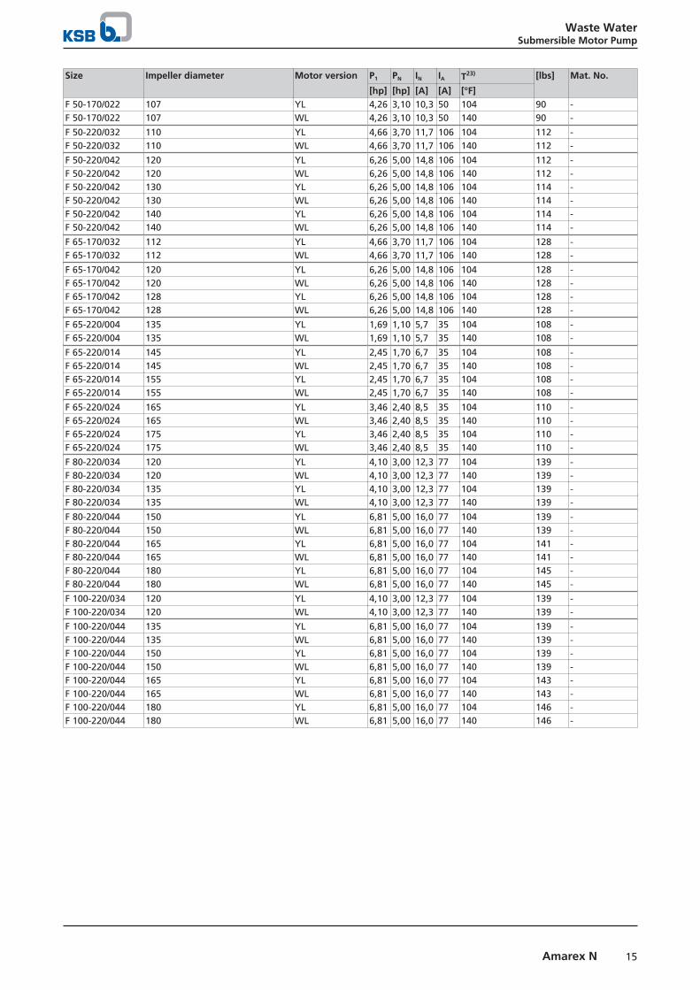
Technical data 3~ 208 V, material variant G
Size Impeller diameter Motor version P1 PN IN IA T23) [lbs] Mat. No.
[hp] [hp] [A] [A] [°F]S 50-170/012 100 YL 3,53 2,55 8,9 50 104 86 -S 50-170/012 100 WL 3,53 2,55 8,9 50 140 86 -S 50-170/012 110 YL 3,53 2,55 8,9 50 104 86 -S 50-170/012 110 WL 3,53 2,55 8,9 50 140 86 -
S 50-170/022 120 YL 4,26 3,10 10,3 50 104 86 -S 50-170/022 120 WL 4,26 3,10 10,3 50 140 86 -S 50-170/022 130 YL 4,26 3,10 10,3 50 104 86 -S 50-170/022 130 WL 4,26 3,10 10,3 50 140 86 -
S 50-220/042 130 YL 6,26 5,00 14,8 106 104 119 -S 50-220/042 130 WL 6,26 5,00 14,8 106 140 119 -S 50-220/042 140 YL 6,26 5,00 14,8 106 104 119 -S 50-220/042 140 WL 6,26 5,00 14,8 106 140 119 -S 50-220/042 150 YL 6,26 5,00 14,8 106 104 119 -S 50-220/042 150 WL 6,26 5,00 14,8 106 140 119 -S 50-220/042 158 YL 6,26 5,00 14,8 106 104 119 -S 50-220/042 158 WL 6,26 5,00 14,8 106 140 119 -
F 50-170/002 90 YL 2,48 1,70 7,2 50 104 90 -F 50-170/002 90 WL 2,48 1,70 7,2 50 140 90 -
Waste WaterSubmersible Motor Pump
15Amarex N
Size Impeller diameter Motor version P1 PN IN IA T23) [lbs] Mat. No.
[hp] [hp] [A] [A] [°F]F 50-170/022 107 YL 4,26 3,10 10,3 50 104 90 -F 50-170/022 107 WL 4,26 3,10 10,3 50 140 90 -
F 50-220/032 110 YL 4,66 3,70 11,7 106 104 112 -F 50-220/032 110 WL 4,66 3,70 11,7 106 140 112 -
F 50-220/042 120 YL 6,26 5,00 14,8 106 104 112 -F 50-220/042 120 WL 6,26 5,00 14,8 106 140 112 -F 50-220/042 130 YL 6,26 5,00 14,8 106 104 114 -F 50-220/042 130 WL 6,26 5,00 14,8 106 140 114 -F 50-220/042 140 YL 6,26 5,00 14,8 106 104 114 -F 50-220/042 140 WL 6,26 5,00 14,8 106 140 114 -
F 65-170/032 112 YL 4,66 3,70 11,7 106 104 128 -F 65-170/032 112 WL 4,66 3,70 11,7 106 140 128 -
F 65-170/042 120 YL 6,26 5,00 14,8 106 104 128 -F 65-170/042 120 WL 6,26 5,00 14,8 106 140 128 -F 65-170/042 128 YL 6,26 5,00 14,8 106 104 128 -F 65-170/042 128 WL 6,26 5,00 14,8 106 140 128 -
F 65-220/004 135 YL 1,69 1,10 5,7 35 104 108 -F 65-220/004 135 WL 1,69 1,10 5,7 35 140 108 -
F 65-220/014 145 YL 2,45 1,70 6,7 35 104 108 -F 65-220/014 145 WL 2,45 1,70 6,7 35 140 108 -F 65-220/014 155 YL 2,45 1,70 6,7 35 104 108 -F 65-220/014 155 WL 2,45 1,70 6,7 35 140 108 -
F 65-220/024 165 YL 3,46 2,40 8,5 35 104 110 -F 65-220/024 165 WL 3,46 2,40 8,5 35 140 110 -F 65-220/024 175 YL 3,46 2,40 8,5 35 104 110 -F 65-220/024 175 WL 3,46 2,40 8,5 35 140 110 -
F 80-220/034 120 YL 4,10 3,00 12,3 77 104 139 -F 80-220/034 120 WL 4,10 3,00 12,3 77 140 139 -F 80-220/034 135 YL 4,10 3,00 12,3 77 104 139 -F 80-220/034 135 WL 4,10 3,00 12,3 77 140 139 -
F 80-220/044 150 YL 6,81 5,00 16,0 77 104 139 -F 80-220/044 150 WL 6,81 5,00 16,0 77 140 139 -F 80-220/044 165 YL 6,81 5,00 16,0 77 104 141 -F 80-220/044 165 WL 6,81 5,00 16,0 77 140 141 -F 80-220/044 180 YL 6,81 5,00 16,0 77 104 145 -F 80-220/044 180 WL 6,81 5,00 16,0 77 140 145 -
F 100-220/034 120 YL 4,10 3,00 12,3 77 104 139 -F 100-220/034 120 WL 4,10 3,00 12,3 77 140 139 -
F 100-220/044 135 YL 6,81 5,00 16,0 77 104 139 -F 100-220/044 135 WL 6,81 5,00 16,0 77 140 139 -F 100-220/044 150 YL 6,81 5,00 16,0 77 104 139 -F 100-220/044 150 WL 6,81 5,00 16,0 77 140 139 -F 100-220/044 165 YL 6,81 5,00 16,0 77 104 143 -F 100-220/044 165 WL 6,81 5,00 16,0 77 140 143 -F 100-220/044 180 YL 6,81 5,00 16,0 77 104 146 -F 100-220/044 180 WL 6,81 5,00 16,0 77 140 146 -

Waste WaterSubmersible Motor Pump
16 Amarex N
Characteristic curves
n = 3500 rpm
Amarex N S 50-170, n = 3500 rpmOn request, the pump's operating point can be verified to Hydraulic Institute acceptance standard Level B. The characteristiccurves refer to the effective motor speed.
The illustrated characteristic curves were measured at 460 V/60 Hz. For characteristic curves at different voltages refer to KSB'spump selection program.
0 20 40 60 80 100 120 140Q [US.gpm]
0 10 20 30Q [m³/h]
0 2 4 6 8Q [l/s]
20
40
60
80
H [ft]
10
20
H [m]
0 20 40 60 80 100 120Q [IM.gpm]
ø130
ø120
ø110
ø100
42.3
4139.5
38
34
28
2010
42.7
41
41
39.5
39.5
38
38
34
34
2820
10
38.0
34
34
28
20
10
31.6
28
28
20
10
η [%]
AN6050170SE/0
1
2
3
4
P [hp]
1
2
3
P [kW]
0 20 40 60 80 100 120 140Q [US.gpm]
ø130ø120
ø110
ø100
Fig. 1: Free passage 3/8" [10 mm]

Waste WaterSubmersible Motor Pump
17Amarex N
Amarex N S 50-220, n = 3500 rpmOn request, the pump's operating point can be verified to Hydraulic Institute acceptance standard Level B. The characteristiccurves refer to the effective motor speed.
The illustrated characteristic curves were measured at 460 V/60 Hz. For characteristic curves at different voltages refer to KSB'spump selection program.
0 20 40 60 80 100 120 140Q [US.gpm]
0 10 20 30Q [m³/h]
0 2 4 6 8Q [l/s]
40
60
80
100
120
140
160
H [ft]
20
30
40
H [m]
0 20 40 60 80 100 120Q [IM.gpm]
ø150
ø158
ø130
38
30
20
46
4442
38
30
20
44.7
44
44
42
42
38
30
20
41.7
38
38
30
20
η [%]
AN6050220SE/0
2
3
4
5
6
P [hp]2
3
4
P [kW]
0 20 40 60 80 100 120 140Q [US.gpm]
ø158 ø150 ø140
ø130
ø140
Fig. 2: Free passage 3/8" [10 mm]
Waste WaterSubmersible Motor Pump
18 Amarex N
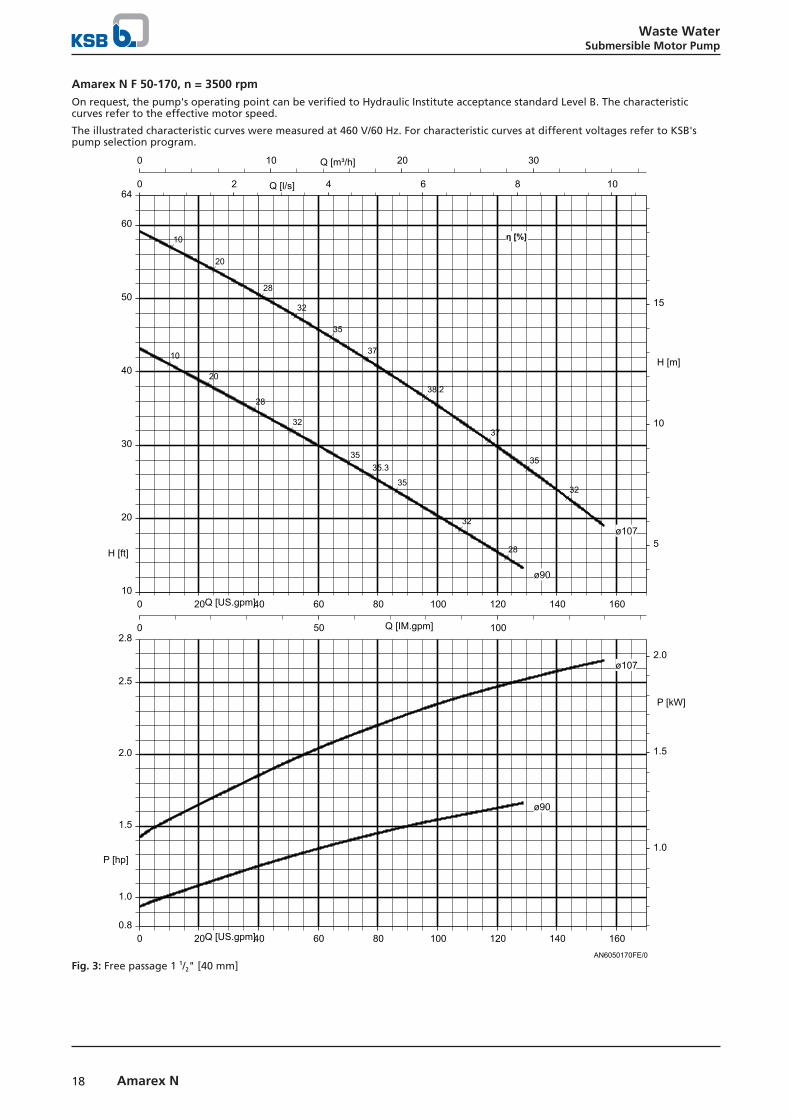
Amarex N F 50-170, n = 3500 rpmOn request, the pump's operating point can be verified to Hydraulic Institute acceptance standard Level B. The characteristiccurves refer to the effective motor speed.
The illustrated characteristic curves were measured at 460 V/60 Hz. For characteristic curves at different voltages refer to KSB'spump selection program.
AN6050170FE/0
0 20 40 60 80 100 120 140 160Q [US.gpm]
0 10 20 30Q [m³/h]
0 2 4 6 8 10Q [l/s]
10
20
30
40
50
60
64
H [ft]5
10
15
H [m]
0 50 100Q [IM.gpm]
1.0
1.5
2.0
2.5
0.8
2.8
P [hp]1.0
1.5
2.0
P [kW]
0 20 40 60 80 100 120 140 160Q [US.gpm]
ø107
ø107
ø90
ø90
38.2
37
37
35
35
32
32
28
20
10
35.335
35
32
32
28
28
20
10
η [%]
Fig. 3: Free passage 1 1/2" [40 mm]

Waste WaterSubmersible Motor Pump
19Amarex N
Amarex N F 50-220, n = 3500 rpmOn request, the pump's operating point can be verified to Hydraulic Institute acceptance standard Level B. The characteristiccurves refer to the effective motor speed.
The illustrated characteristic curves were measured at 460 V/60 Hz. For characteristic curves at different voltages refer to KSB'spump selection program.
0 50 100 150 200Q [US.gpm]
0 10 20 30 40Q [m³/h]
0 2 4 6 8 10 12Q [l/s]
20
40
60
80
100
120
H [ft]10
20
30
H [m]
0 50 100 150Q [IM.gpm]
ø140
ø130
ø120
ø110
36
30
20
45.9
44
44
42
42
40
3630
20
46.7
46
46
44
44
42
42
40
40
36
36
3020
47.0
46
46
44
44
42
42
40
40
36
36
3020
η [%]
5.5
AN6050220FE/0
2
4
0.5
P [hp]2
4
P [kW]
0 50 100 150 200Q [US.gpm]
ø140 ø130
ø120
ø110
Fig. 4: Free passage 1 1/2" [40 mm]

Waste WaterSubmersible Motor Pump
20 Amarex N
Amarex N F 65-170, n = 3500 rpmOn request, the pump's operating point can be verified to Hydraulic Institute acceptance standard Level B. The characteristiccurves refer to the effective motor speed.
The illustrated characteristic curves were measured at 460 V/60 Hz. For characteristic curves at different voltages refer to KSB'spump selection program.
0 50 100 150 200 250 300Q [US.gpm]
0 20 40 60Q [m³/h]
0 5 10 15 20Q [l/s]
10
20
30
40
50
60
70
78
H [ft]5
10
15
20
H [m]
0 100 200Q [IM.gpm]
ø120
ø112
40.7
40
40
38
38
35
35
30
30
2010
39.3
38
38
35
30
20
10
η [%]
AN6065170FE/0
3
4
5
6
2.4
6.6
P [hp]
2
3
4
P [kW]
0 50 100 150 200 250 300Q [US.gpm]
ø120
ø112
Fig. 5: Free passage 2 1/2" [65 mm]

Waste WaterSubmersible Motor Pump
21Amarex N
n = 1750 rpm
Amarex N F 65-220, n = 1750 rpmOn request, the pump's operating point can be verified to Hydraulic Institute acceptance standard Level B. The characteristiccurves refer to the effective motor speed.
The illustrated characteristic curves were measured at 460 V/60 Hz. For characteristic curves at different voltages refer to KSB'spump selection program.
AN6065220FE/0
0 50 100 150 200 250Q [US.gpm]
0 20 40Q [m³/h]
0 5 10 15Q [l/s]
10
15
20
25
30
35
7
38
H [ft]4
6
8
10
H [m]
0 50 100 150 200Q [IM.gpm]
0.5
1.0
1.5
2.0
2.4
P [hp]0.5
1.0
1.5
P [kW]
0 50 100 150 200 250Q [US.gpm]
ø175
ø175
ø165
ø165
ø155
ø155
ø145
ø145
ø135
ø135
51.4
51
51
49
49
4541
3730
2010
50.4
49
49
45
4137
3020
10
54.2
53
53
51
51
49
4541
3730
2010
54.2
53
53
51
51
49
49
4541
3730
2010
52.3
51
51
49
49
45
45
4137
3020
10
η [%]
Fig. 6: Free passage 2 1/2" [65 mm]

Waste WaterSubmersible Motor Pump
22 Amarex N
Amarex N F 80-220, n = 1750 rpmOn request, the pump's operating point can be verified to Hydraulic Institute acceptance standard Level B. The characteristiccurves refer to the effective motor speed.
The illustrated characteristic curves were measured at 460 V/60 Hz. For characteristic curves at different voltages refer to KSB'spump selection program.
0 100 200 300 400 500Q [US.gpm]
0 20 40 60 80 100 120Q [m³/h]
0 10 20 30Q [l/s]
10
5.5
20
30
40
50
6
H [ft]5
10
15
H [m]
0 100 200 300 400Q [IM.gpm]
ø180
ø165
ø150ø135
ø120
54
5048
45
38
3020
55.3
54
54
50
50
4845
3830
20
52.4
50
50
48
48
45
45
3830
20
50.0
48
48
45
45
3830
20
46.345
45
38
38
3020
η [%]
AN6080220FE/0
2
4
6
0.5
P [hp]2
4
P [kW]
0 100 200 300 400 500Q [US.gpm]
ø180 ø165
ø150
ø135
ø120
Fig. 7: Free passage = 3" [76 mm]

Waste WaterSubmersible Motor Pump
23Amarex N
Amarex N F 100-220, n = 1750 rpmOn request, the pump's operating point can be verified to Hydraulic Institute acceptance standard Level B. The characteristiccurves refer to the effective motor speed.
The illustrated characteristic curves were measured at 460 V/60 Hz. For characteristic curves at different voltages refer to KSB'spump selection program.
0 100 200 300 400 500 600Q [US.gpm]
0 50 100Q [m³/h]
0 10 20 30 40Q [l/s]
10
5.5
20
30
40
2
48
H [ft]5
10
H [m]
0 100 200 300 400 500Q [IM.gpm]
ø180
ø165
ø150ø135
ø120
45
4035
2820
10
48.7
45
4035
2820
10
44.7
40
40
35
35
28
28
2010
41.3
40
40
35
35
28
28
2010
36.735
35
28
28
2010
η [%]
AN60100220FE/0
2
4
6
1
P [hp]
2
4
P [kW]
0 100 200 300 400 500 600Q [US.gpm]
ø180 ø165
ø150
ø135
ø120
Fig. 8: Free passage = 4" [100 mm]

Waste WaterSubmersible Motor Pump
24 Amarex N
Types of installation
Overview of installation types
Installation type S: stationary wet installation Installation type P: transportablemodel
P4
P5P1
P4P5
P1
1)
P1
P6
Guide cable arrangement Twin guide rail arrangementP1: pumpP4: installation parts for guide cablearrangementP5: claw
1) = Not included in KSB's scope ofsupply
P1: pumpP4: installation parts for twin guide railarrangementP5: claw and adapter
P1: pumpP6: foot
Installation information
Suggested installation layouts for stationary pump setsGuide cable or twin guide rail arrangementAmarex N 50 (2″), 65 (2 1/2″), 80 (3″), 100 (4″)
P1
P4
P7
P4
P7
P1≥ DN1
Suggestion 1Guide cable or twin guide rail arrangementSingle-pump stationFlanged base elbow
Suggestion 2Guide cable or twin guide rail arrangementDual-pump stationFlanged base elbow

Waste WaterSubmersible Motor Pump
25Amarex N
DimensionsGuide cable arrangementAmarex N 50 (2″), 65 (2 1/2″), 80 (3″), 100 (4″)
DN2
B
≥ DN 1
L
ØA
≥ DN1
E
ØD
E
Na)
Ma)
O
Single-pump stationFlanged base elbow
Dual-pump stationFlanged base elbow
a) Minimum
Dimensions [″]Amarex N Ø A B Ø D E L M N O DN 1 DN2
S 50-170 /F 50-170
1 pump 24 39/64 6 1/2 39 3/8 - 1 21/32 - - - 2 22 pumps - 9 1/4 39 3/8 11 13/16 - 21 21/32 27 9/16 7 7/8 2 2
S 50-222 / F 50-220
1 pump 24 39/64 6 1/2 39 3/8 - 1 21/32 - - - 2 22 pumps - 9 1/4 39 3/8 11 13/16 - 21 21/32 27 9/16 7 7/8 2 2
F 65-170 / F 65-220
1 pump 24 39/64 6 57/64 39 3/8 - 3 5/8 - - - 2 1/2 2 1/2
2 pumps - 14 11/64 47 1/4 23 5/8 - 21 21/32 39 3/8 5 5/16 2 1/2 2 1/2
F 80-220 1 pump 24 39/64 7 7/8 39 3/8 - 63/64 - - - 3 32 pumps - 12 19/32 47 1/4 23 5/8 - 23 5/8 39 3/8 6 39/64 3 3
F 100-220 1 pump 24 39/64 7 7/8 39 3/8 - 2 9/16 - - - 4 42 pumps - 12 19/32 47 1/4 23 5/8 - 23 5/8 39 3/8 5 3/64 4 4

Waste WaterSubmersible Motor Pump
26 Amarex N
Dimensions
Amarex N, transportable model
2)
1)
b2
e2
a 2
R2
DN2
DN1
b3
f 2
1) Lowest switch-off point for automatic operation
2) Minimum submergence for continuous operation
Pump dimensions [″]Size Pump
DN1 DN2 a2 24) b2 b3 e2 f2
24) R2
S/F 50-170 2 2 21 17/32 12 43/64 11 17/32 7 3/32 5 63/64 8 5/32
S/F 50-220 2 2 23 31/32 13 15/64 12 3/32 7 3/32 6 7/64 8F 65-170 2 1/2 2 1/2 25 45/64 14 29/64 13 5/16 8 17/64 6 29/64 9 49/64
F 65-220 2 1/2 2 1/2 23 11/32 13 57/64 13 21/32 8 17/64 6 27/64 9 61/64
F 80-220 3 3 26 29/64 15 13/64 15 7/16 9 1/16 7 23/64 9 51/64
F 100-220 4 4 27 31/64 15 5/64 15 23/64 9 1/16 8 5/32 10 29/32
Pump flange DN₂DN 50 (2″) and DN 65 (2 ¹/₂″)ISO 7005 PN10 - PN16
DN 80 (3″) and DN 100 (4″)ISO 7005 PN10 - PN16
Hf
kf
R 3/8
Df
DN2
R 3 / 8
kf
Df
Hf
22°30‘
22
°30
‘
DN2
Pump flange dimensions [″]Size Flange
Hf kf Df Zf
S/F 50-170 4 59/64 4 59/64 5 33/64 4S/F 50-220 4 59/64 4 59/64 5 33/64 4F 65-170 5 43/64 5 45/64 6 29/64 4F 65-220 5 43/64 5 45/64 6 29/64 4F 80-220 7 3/32 6 19/64 7 3/32 4F 100-220 7 61/64 7 3/32 8 5/64 4
24) If a foot plate is fitted, a₂ + ³/₈″ [10 mm]

Waste WaterSubmersible Motor Pump
27Amarex N
Amarex N 50, stationary installation, guide cable arrangement, straight claw
DN 3 = DN 50: ASME = standard
Guide cable arrangement
1)
2)
a)
2 23/64
3 11/32
3 15
/ 16
Ø 25
/ 64
k1
b1
DN3
4 59/64
Ø 3/8DN1
l1
h1
R1
R3 a 1
f 1
g25
/ 32
B
C
AA
2 3 /
8
4 59/64
1 31/32
13/ 64
15/ 3225/32
S
B
15/32
19/ 32
Installation in the sump
AE
D2
B2D1
B1
CA - A C
DN2
O a)
P a)
dm
N a)
J J
1) Lowest switch-off point for automatic operation 2) Minimum submergence for continuous operation
a) Minimum
Pump dimensions [″]Size DN1 DN2 a1 b1 d f1 g h1 k1 l1 m R1 R3 [lbs]S 50-170 - 2 18 1/2 14 51/64 9 27/32 4 1/8 4 1/8 1 7/32 18 37/64 19 49/64 4 59/64 6 21/64 19 23/32 86F 50-170 2 2 18 1/2 14 51/64 9 27/32 4 1/8 7 7/8 1 7/32 18 37/64 19 49/64 4 59/64 6 21/64 19 23/32 95S 50-220 - 2 20 15/16 15 5/16 10 4 1/8 7 7/8 1 1/16 19 7/32 20 15/64 5 5/64 6 1/32 22 119F 50-220 2 2 20 15/16 15 5/16 10 4 1/8 7 7/8 1 1/16 19 7/32 20 15/64 5 5/64 6 1/32 22 119
Foundation dimensions [″]A B1 B2 C D1 D2 E J N O P S7 9/32 4 21/64 4 23/32 4 59/64 3 5/32 3 15/16
63/6415/32 18 7/32 18 19/64 13 25/32 3 7/64
Elbow flange DN3
DN 50 (2″ )ASME 150 lb 2″
Df
DN
3
gf
k f
Zf x 45/64
Hf
Elbow flange dimensions DN3 [″]Flange design DN3 Df gf Hf kf Zf
ASME 150 lb 2″ 1 31/32 4 23/32 4 1/64 5 1/8 4 3/4 4

Waste WaterSubmersible Motor Pump
28 Amarex N
Amarex N 50, stationary installation, guide cable arrangement, inclined claw
DN 3 = DN 50: ASME = standard
Guide cable arrangement
2563:129
2)
k1
b1
C
4 59/64DN3
Ø 3/8
l1
R3 a 1
h1 f 1
g
2 3 /
8
AA
25/ 321)
R1
RS
RS
1 31/32
13/ 64
15/ 3225/32
S
B
15/32
19/ 32
Installation in the sump
AE
D2
B2D1
B1
CA - A C
DN2
O a)
P a)
dm
N a)
J J
1) Lowest switch-off point for automatic operation 2) Minimum submergence for continuous operation
a) Minimum
Pump dimensions [″]Size DN1 DN2 a1 b1 d f1 g h1 k1 l1 m R1 R3 RS [lbs]S 50-170 - 2 18 1/2 14 51/64 9 27/32 4 1/8 4 1/8 1 7/32 18 37/64 19 49/64 4 59/64 6 21/64 19 23/32 - 86F 50-170 - 2 18 1/2 14 51/64 9 27/32 4 1/8 7 7/8 1 7/32 18 37/64 19 49/64 4 59/64 6 21/64 19 23/32 6 11/32 95S 50-220 - 2 20 15/16 15 5/16 10 4 1/8 7 7/8 1 1/16 19 7/32 20 15/64 5 5/64 6 1/32 22 - 119F 50-220 - 2 20 15/16 15 5/16 10 4 1/8 7 7/8 1 1/16 19 7/32 20 15/64 5 5/64 6 1/32 22 6 11/32 119
Foundation dimensions [″]A B1 B2 C D1 D2 E J N O P7 9/32 4 21/64 4 23/32 4 59/64 3 5/32 3 15/16
63/6415/32 18 7/32 18 19/64 13 25/32
Elbow flange DN3
DN 50 (2″)ASME 150 lb 2″
Df
DN
3
gf
k f
Zf x 45/64
Hf
Elbow flange dimensions DN3 [″]Flange design DN3 Df gf Hf kf Zf
ASME 150 lb 2″ 1 31/32 4 23/32 4 1/64 5 1/8 4 3/4 4

Waste WaterSubmersible Motor Pump
29Amarex N
Amarex N 50, stationary installation, twin guide rail arrangement, inclined claw
DN 3 = DN 50: ASME = standard
Twin guide rail arrangement
1)
2)
3E
3 11/32
k1
b1
4 29/64
DN3R3
R1
a 1h
1
DN1
l1
Ø 3/8
2 3 /
8f 1
gØ
25/ 64
D
A A
3)Ø 1 21/64 x 1/8
RS
RS
S
2 11
/ 64
2 49/64
1 31/32
15/ 32
15/ 32
E
Installation in the sump
AE
D2
B2D1
B1
CA - A C
DN2
O a)
P a)
dm
N a)
J J
1) Lowest switch-off point for automatic operation 2) Minimum submergence for continuous operation
3) Not included in KSB's scope of supply a) Minimum
Pump dimensions [″]Size DN1 DN2 a1 b1 d f1 g h1 k1 l1 m R1 R3 RS [lbs]S 50-170 - 2 19 29/64 16 39/64 9 27/32 4 9/64 7 7/8 2 1/8 19 41/64 20 25/32 4 59/64 8 21/32 21 21/32 6 11/32 86F 50-170 2 2 19 29/64 16 39/64 9 27/32 4 9/64 7 7/8 2 1/8 19 41/64 20 25/32 4 59/64 8 21/32 21 21/32 - 95S 50-220 - 2 21 39/64 16 49/64 10 4 9/64 7 7/8 2 3/32 19 59/64 21 1/16 5 5/64 9 1/16 23 55/64 6 11/32 119F 50-220 2 2 21 39/64 16 49/64 10 4 9/64 7 7/8 2 3/32 19 59/64 21 1/16 5 5/64 9 1/16 23 55/64 - 119
Foundation dimensions [″]A B1 B2 C D1 D2 E J N O P S7 9/32 4 21/64 4 23/32 4 59/64 3 5/32 3 15/16
63/6415/32 18 57/64 18 57/64 13 25/32 1 31/32
Elbow flange DN3
DN 50 (2″)ASME 150 lb 2″
Df
DN
3
gf
k f
Zf x 45/64
Hf
Elbow flange dimensions DN3 [″]Flange design DN3 Df gf Hf kf Zf
ASME 150 lb 2″ 1 31/32 4 23/32 4 1/64 5 1/8 4 3/4 4

Waste WaterSubmersible Motor Pump
30 Amarex N
Amarex N 65, stationary installation, guide cable arrangement
DN 3 = 65/65: ASME = standard
Guide cable arrangement
1)
2)
a)
B2 23/64
Ø 25
/ 64
3 11/323
15/ 16C
k1
b1
R3 a 1
R1
h1
DN3
25/ 32
g
f 12
3 /8
l1
DN1
Ø 3/8
AA
6 1/2
6 1/2
B
S
25/32
1 31/32
13/ 64
15/ 32
19/ 3215/32
Installation in the sump
AE
D2
B2D1
B1
CA - A C
DN2
O a)
P a)
dm
N a)
J J
1) Lowest switch-off point for automatic operation 2) Minimum submergence for continuous operation
a) Minimum
Pump dimensions [″]Size DN1 DN2 a1 b1 d f1 g h1 k1 l1 m R1 R3 RS [lbs]F 65-170 2 1/2 2 1/2 22 49/64 16 39/64 9 7/8 5 29/32 10 15/64 2 13/32 21 31/32 22 61/64 5 9 7/32 25 5/32 6 21/64 119
F 65-220 2 1/2 2 1/2 20 25/64 16 1/32 10 7/16 5 29/32 10 15/64 2 31/64 21 27/64 22 13/32 5 19/32 9 31/64 22 7/8 6 21/64 100
Foundation dimensions [″]A B1 B2 C D1 D2 E J N O P8 15/32 4 23/32 5 33/64 6 1/2 3 11/32 4 23/32
63/6415/32 19 11/16 19 11/16 15 3/4
Elbow flange DN
DN 65 (2 ¹/₂″)ASME 150 lb 2 1/2″
Df
DN
3
gf
k f
Zf x 53/64
Hf
Elbow flange dimensions DN3 [″]Flange design DN3 Df gf Hf kf Zf
ASME 150 lb 2 1/2 5 33/64 4 51/64 5 29/32 5 33/64 4

Waste WaterSubmersible Motor Pump
31Amarex N
Amarex N 65, stationary installation, twin guide rail arrangement
DN 3 = 65: ASME = standard
Twin guide rail arrangement
1)
2)
3E
3 11/32
Ø 25
/ 64
k1
D
b1
6 1/32
DN3
6 1/23/8
l1
DN1
R3
R1
a 1h
1
A A
2 3 /
8f 1
g
3)
Ø 1 21/64 x 1/8
2 49/64E1 31/32
15/ 32
S
2 11
/ 64
15/ 32
Installation in the sump
AE
D2
B2D1
B1
CA - A C
DN2
O a)
P a)
dm
N a)
J J
1) Lowest switch-off point for automatic operation 2) Minimum submergence for continuous operation
3) Not included in KSB's scope of supply a) Minimum
Pump dimensions [″]Size DN1 DN2 a1 b1 d f1 g h1 k1 l1 m R1 R3 [lbs]F 65-170 - 2 1/2 22 49/64 18 27/64 9 7/8 5 29/32 10 15/64 2 13/32 23 5/32 24 9/64 5 9 7/32 25 5/32 119
F 65-170 2 1/2 2 1/2 22 49/64 18 27/64 9 7/8 5 29/32 10 15/64 2 13/32 23 5/32 24 9/64 5 5 19/32 25 5/32 119
F 65-220 - 2 1/2 20 25/64 17 7/8 10 7/16 5 29/32 10 15/64 2 31/64 22 19/32 23 37/64 5 19/32 9 31/64 22 7/8 99
F 65-220 2 1/2 2 1/2 20 25/64 17 7/8 10 7/16 5 29/32 10 15/64 2 31/64 22 19/32 24 9/64 5 19/32 9 31/64 22 7/8 99
Foundation dimensions [″]A B1 B2 C D1 D2 E J N O P8 5/16 4 23/32 5 33/64 6 1/2 3 11/32 4 23/32
63/6415/32 21 21/32 21 21/32 15 3/4
Elbow flange DN3
DN 65 (2 ¹/₂″)ASME 150 lb 2 1/2″
Df
DN
3
gf
k f
Zf x 53/64
Hf
Elbow flange dimensions DN3 [″]Flange design DN3 Df gf Hf kf Zf
ASME 150 lb 2 1/2 ″ 2 1/2 5 33/64 4 51/64 5 29/32 5 33/64 4

Waste WaterSubmersible Motor Pump
32 Amarex N
Amarex N 80 and 100, stationary installation, guide cable arrangement
DN 3 = 80/80: ASME = standard
Guide cable arrangement
2)
1)
a)
B
2 23/64
3 15
/ 16 3 11/32
Ø 25
/ 64
C
k1
b1
G
DN3
H
DN1
l1
Ø 45/64
h1
a 1
R1
R3
g4
5 /16
f 1A A
1 31/32
B
25/3215/32
6 1/2
19/ 32
15/ 32
13/ 64
Installation in the sump
a)
a)
a)
B
A - A C
DB D
C
AE
O
DN2
dm
P
N
1) Lowest switch-off point for automatic operation 2) Minimum submergence for continuous operation
a) Minimum
Pump dimensions [″]Size DN1 DN2 a1 b1 d f1 g h1 k1 l1 m R1 R3 [lbs]F 80-220 3 3 22 29/32 18 13/16 12 43/64 7 7/8 12 19/32 4 3/64 23 25/32 27 21/64 6 59/64 10 5/16 26 31/32 145
F 100-220 4 4 23 3/4 18 3/4 12 33/64 8 17/64 13 37/64 3 55/64 25 15/64 27 13/64 6 21/32 10 1/64 27 19/32 148
Foundation dimensions [″]Size A B C D E G H J N O PF 80-220 11 13/16 7 7/8 8 21/32 5 29/32 1 37/64 6 27/64 6 45/64
25/32 21 21/32 21 21/32 15 3/4
F 100-220 11 13/16 7 7/8 8 21/32 5 29/32 1 37/64 8 8 17/6425/32 21 21/32 21 21/32 15 3/4
Elbow flange DNDN 80 (3″)ASME 150 lb 3″
DN 100 (4″)ASME 150 lb 4″
gf
DN3 k f
Df
Z f x 45 / 64
Zf x 45/64
gf
k f
Df
Ø80
Elbow flange dimensions DN3 [″]Flange design DN3 gf kf Df Zf
ASME 150 lb 3 5 6 7 33/64 44 6 9/64 7 1/2 8 21/32 8

Waste WaterSubmersible Motor Pump
33Amarex N
Amarex N 80 and 100, stationary installation, twin guide rail arrangement
DN 3 = 80/80 or 80/100 or 100/100: ASME = standard
Twin guide rail arrangement
2)
1)
3)
E 3 25/64
3 11/32
Ø 25
/ 64
Dk1
b1
G1
DN3
a 1
R3
R1
h1
DN1
l1
Ø 45/64
H
g
f 1
A A
4 5 /
16
E2 49/64
1 31/32
2 11
/ 64
15/ 32
S
15/ 32
Installation in the sump
a)
a)
a)
B
A - A C
DB D
C
AE
O
DN2
dm
P
N
1) Lowest switch-off point for automatic operation 2) Minimum submergence for continuous operation
3) Not included in KSB's scope of supply a) Minimum
Pump dimensions [″]Size DN1 DN2 DN3 a1 b1 d f1 g h1 k1 l1 m R1 R3 [lbs]F 80-220 3 3 3 22 29/32 19 59/64 12 43/64 7 7/8 12 19/32 4 1/16 24 51/64 28 11/32 6 59/64 10 5/16 26 31/32 145
4F 100-220 4 4 4 23 3/4 20 53/64 12 33/64 8 17/64 13 37/64 3 55/64 26 17/32 28 1/2 6 21/32 11 1/32 27 19/32 147
Foundation dimensions [″]Size A B C D E G1 H J N O PF 80-220 11 13/16 7 7/8 8 21/32 5 29/32 1 37/64 6 11/16 6 11/16
25/32 22 53/64 22 53/64 15 3/4
F 100-220 11 13/16 7 7/8 8 21/32 5 29/32 1 37/64 8 17/64 8 17/6425/32 23 5/8 23 5/8 15 3/4
Elbow flange DNDN 80 (3″)ASME 150 lb 3″
DN 100 (4″)ASME 150 lb 4″
gf
DN3 k f
Df
Z f x 45 / 64
Zf x 45/64
gf
k f
Df
Ø80
Elbow flange dimensions DN3 [″]Flange design DN3 gf kf Df Zf
ASME 150 lb 3 5 6 7 33/64 44 6 9/64 7 1/2 8 21/32 8

Waste WaterSubmersible Motor Pump
34 Amarex N
Scope of supply
Transportable model for wet installation (installationtype P)▪ Pump set complete with power cable
▪ Feet (and foot plate, if applicable)
Stationary wet installation (installation type S)▪ Pump set complete with power cable
▪ Claw with sealing and mounting elements
▪ Mounting bracket with mounting elements
▪ Base elbow and mounting elements
Accessories
Installation parts for stationary pump sets
Overview of installation parts for stationary installation
Item Description Sizes Connection Mat. No. [lbs] [kg]Guide cable arrangement
P4 +P5
Installation parts for stationary wetinstallation (guide cable arrangement)
Consisting of: flanged base elbow,suspension bracket, mounting bracket,claw with stainless steel screws/bolts
Amarex NInclined claw
DN 50/50: ASME 39023284 43 19,5
Amarex NStraight claw
DN 50/50: ASME 39023283 32 14,5
Amarex N DN 65/65: ASME 39023285 39 17,6Amarex N DN 80/80: ASME 39023286 65.3 29,6Amarex N DN 80/100: ASME 39023523 65.0 29,5Amarex N DN 100/100: ASME 39023287 70.5 32
Twin guide rail arrangementP4 +P5
Installation parts for stationary wetinstallation (twin guide railarrangement)
Consisting of: flanged base elbow,mounting bracket, adapter, claw withstainless steel screws/bolts, (guide railsnot included in KSB's scope of supply)
Amarex NInclined claw
DN 50, DN3: ASME 39023274 31 14
Amarex NStraight claw
DN 50, DN3: ASME 39023275 46.3 21
Amarex N DN 80, DN3: ASME 39023276 75 34Amarex N DN 80/100, DN3: ASME 39023522 75 34Amarex N DN 100, DN3: ASME 39023277 80 36
ClawP5 Claw Amarex N A48 Class 40B with
stainless steel screws
Guide cable arrangement
Amarex NStraight claw
DN 50 39022248 2.4 1,2
Amarex NInclined claw
DN 50 39022252 15.4 7
Amarex N DN 65 39021018 4.2 2Amarex N DN 80 / DN 100 39021020 6.8 3,5
P5 Claw Amarex N A48 Class 40B withstainless steel screws/bolts
Twin guide rail arrangement
Amarex NInclined claw
DN 50 39022990 13.2 6
Amarex NStraight claw
DN 65 39022993 16.1 7,3
DN 80 39022996 21.4 9,7DN 100 39022999 32.4 14,7
Lifting bail

Waste WaterSubmersible Motor Pump
35Amarex N
Item Description Sizes Connection Mat. No. [lbs] [kg]- Lifting bail made of stainless steel 304
with screws/bolts made of stainless steel316, for lowering the pump set at anangle
Amarex N S 50-170 39022395 1.3 0,6
Amarex N S 50-220, F 50-170, F 50-220,F 65-170, F 80-220, F 100-220
39018004 2.2 1
- Lifting bail made of stainless steel 304with screws/bolts made of stainless steel316, for lowering the pump set in aperfectly vertical position
Amarex N DN 32 / DN 50 39023593 1.76 0,85
DN 65 / DN 80 / DN 100 39023594 2.65 1,2
Conversion parts- Conversion parts for conversion to twin
guide rail arrangement, consisting of:mounting bracket, stainless steel screws/bolts, adapter, anchor bolts
Amarex N DN 50/DN 65 39023308 0.9 0,4
DN 80/DN 100 39023310 5.5 2,5
Installation parts for transportable pump sets
Overview of installation parts for transportable pump sets
Item Description Sizes Mat. No. [lbs] [kg]P6 3 feet Amarex N DN 50, 65, 80, 100 39022260 0.9 0,4
Foot plate including screws
(only for uneven mounting surfaces and incombination with feet)
Amarex N DN 50, 65, 80, 100 39022262 2.0 0,9
Chain for stationary and transportable pump sets
Overview of chains for stationary and transportable pump sets
Item Description Sizes Mat. No. [lbs] [kg]P7 Chain made of stainless steel 316 with shackle made of stainless
steel 304 and hook made of stainless steel 304
Max. load: 1200 lbs [554.3 kg]
9063

KSB, Inc.
4415 Sarellen Road • Richmond, VA 23231
Phone: (804) 222-1818 • Fax: (804) 226-6961
www.ksbusa.com
KSB PUMPS Inc.
5885 Kennedy Road • Mississauga • Ontario L 4Z 2G3
Phone: (905) 568-9200 • Fax: (905) 568-3740
www.ksb.ca
2563
.57/
05-E
N-U
S1/
24/2
017