Embed Size (px)
Citation preview

ALUM
INIU
M ROOFIN
G PANELS
The durable solution to the toughest conditions
ALSULATE-125
®

2 | PERMALITE® Aluminium Roofing Panels ALSULATE-125® 2017
1.0 ALSULATE-125® Aluminium Insulated Roofing System 3
1.1 The benefits of ALSULATE-125® 3
2.0 Design Information 4
2.1 Material Specification 4
2.2 Thermal Protection 4
2.3 Thermal Expansion of Materials 4
2.4 Maximum Span Capacity & Rainwater Drainage Tables 5
2.5 Timber and Metal Compatibility 6
3.0 General Rainwater System Design Recommendations 7
3.1 Installation Details 7
4.0 Sheet Installation 7
4.1 Turn Up The Edge Of The Top Skin 8
4.2 Fixing 8
5.0 Prepare The Remaining Panels As Per Previous Steps 9
6.0 Last Panel Installation 10
7.0 Other Installation Information 11
7.1 Post Painting 11
7.2 Sealants 11
7.3 Expansion Fixing Considerations 11
7.4 Types Of Pierced Fixings 11
7.5 End Laps 12
8.0 ALSULATE-125® System Components 13
8.1 Sheeting 13
8.2 Fixing 13
8.3 End Capping 13
8.4 Barge Capping 14
8.5 Ridge Flashing 14
8.6 Gutter Connection Detail 15
Table of Contents

PERMALITE® Aluminium Roofing Panels ALSULATE-125® 2017 | 3
At last there is a roofing panel which combines the corrosion resistance of aluminium with the exceptional insulation properties of a sandwich panel: introducing new ALSULATE-125® panel from Lysaght.
ALSULATE-125® insulated sandwich panel system is a roofing system with both insulative and structural advantages. The clever sandwich design incorporates both roofing and a prefinished ceiling using 5251 H38 Marine grade aluminium to provide outstanding watertightness, durability and stunning aesthetics. A variety of flashings and ridge covers cap off the roof design.
The self-mating easily installed roof panels provide insulation ratings of R3.4 Winter and R3.3 Summer and free span capacities of up to 6.4m. ALSULATE-125® insulated roof panels provide a clean crisp uninterrupted ceiling finish, reducing the number of unsightly support beams normally associated with traditional roofing methods. ALSULATE-125® insulated roof panels are easily incorporated into all forms of construction with the added benefit of meeting the building regulations insulation requirements. With its unrivalled sustainability and durability credentials, ALSULATE-125® panels makes it easy to specify roofing for your next project.
Aluminium’s formability, high strength-to-weight ratio, corrosion resistance and ease of recycling, makes it the ideal material for a wide range of building applications. It is almost uniquely suited for projects in harsh industrial and marine environments.
Aluminium is a long lasting, durable, lightweight alternative to other cladding materials particularly in corrosive environments. Aluminium provides high thermal insulation and minimal maintenance to remain corrosion-free. It is easier to transport and erect because it is significantly lighter than many alternate cladding materials.
The outstanding benefit of PERMALITE® Aluminium Roofing Products is their long-term durability in aggressive environments. Roofs made from PERMALITE® products have been installed in Australia since the 1960s. This proven track record in Australia’s harshest conditions means you can be assured of an effective roof life significantly longer than for most other roofing materials.
Choosing the optimum material for your next project should take into account the full lifetime of the material. This will include construction, use, maintenance and disposal. Materials which can be recycled easily and economically and which do not require landfill disposal should be preferred.
This booklet is a guide to the installation of aluminium ALSULATE-125® roofing and walling manufactured by Lysaght and should be read in conjunction with the PERMALITE® Aluminium Roofing Solutions manual. (Available at www.permalite.com.au). We intend that it be used by all trades and professions involved with specifying and applying the ALSULATE-125® range of products.
Reference to this document will allow you to maximise the benefits of ALSULATE-125® panels in your next project. We refer only to genuine PERMALITE® aluminium roofing and walling manufactured by us and marketed under our brand names.
Our recommendations should only be used for our products because they are based on comprehensive testing of our profiles, Base Metal Thicknesses (BMT) and material finishes. Our products are engineered to perform according to our specifications only if they are used in the appropriate conditions and installed to the recommendations in this manual and our other publications. Where we recommend use of third party materials, ensure you check the qualities and capabilities of those products with the relevant manufacturer before use.
1.1 The benefits of ALSULATE-125® panels include
• Marine Grade Aluminium linings combine with a EPS core to provide an extremely lightweight structural component reducing material handling costs on site.
• The insulated R values of ALSULATE-125® insulated panels of R3.4 Winter and R3.3 Summer will reduce heating / cooling costs and noise levels as well as increasing thermal comfort levels within the building.
• Long span capacities allow for reduction in support members allowing for structural savings.
• The Integrated prefinished ceiling lining provides project labour, time and material savings.
• Marine grade aluminium linings offer long term low maintenance durability in a wide range of corrosive environments.
• A full range of marine grade aluminium flashings and accessories combined with 304SS screw fixings ensures project durability for the long term.
• PERMALITE® positive fixing system provides time proven security against wind uplift whilst enhancing watertightness.
• The trapezoidal outer cladding profile not only provides for a dynamic aesthetic but allows for roof pitches as low as 1 degree.
1.0 ALSULATE-125® Aluminium Insulated Roofing System

4 | PERMALITE® Aluminium Roofing Panels ALSULATE-125® 2017
2.1 Material Specification
2.0 Design Information
Table 2.1: Alloy Mechanical Properties (Sheeting)
Alloy 5251/ 5052 Marine Grade
Temper/ Hardness H38
Min. Tensile Strength 260 MPa
Min. 0.2% Proof Stress in Tension 220 MPa
Elongation 0.7mm Thickness 3%
Panel Properties
Coverage (mm) 1000mm
Weight (kg/lm) 6.423 kg/lm
Min. Recommended Roof Pitch
1.0 degrees (no end lap)
3.0 degrees (end lapped sheets)
Sheet LengthsMax. 14m
Min. 2m
Table 2.2: EPS Foam Core Properties
Physical Property UnitClass Test
MethodL SL S M H VH
Compressive stress at 10% deformation min. kPa 50 70 85 105 135 165 AS2498.3
Cross - breaking strength; min. kPa 95 135 165 200 269 320 AS2498.4
Rate of water vapour transmission; max. - measured parallel to rise at 23°C
μg/m2s 710 630 580 520 460 400 AS2498.5
Dimensional stability of length; max.: at 70°, dry conditions: 7 days
per cent 1.0 1.0 1.0 1.0 1.0 1.0 AS2498.6
Thermal resistance (min.) at a mean temperature of 25°C (50mm sample)
m2K/W 1 1.13 1.17 1.20 1.25 1.28AS/NZS 4859.1
Flame propagation characteristics:
AS2122.1
- median flame duration; max. seconds 2.0 2.0 2.0 2.0 2.0 2.0
- eighth value; max. seconds 3.0 3.0 3.0 3.0 3.0 3.0
- median volume retained; per cent 15 18 22 30 40 50
- eighth value; min. per cent 12 15 19 27 37 47
2.2 Thermal Protection
Long continuous sheet lengths require careful consideration of thermal behaviour. Although aluminium has twice the coefficient of expansion of steel (24 x 106 compared to 12 x 106 @ 20°C) the effect of this is often over-estimated especially for sandwich panel construction.
Usually aluminium cladding is fixed to a steel structure which, under the same thermal influence, also expands or contracts. The combination of these factors results in a low relative expansion between the aluminium cladding and the steel structure. It has been observed in practice that the theoretical expansion of an aluminium roof, relative to the steel structure on which it is fixed, is reduced by up to 50%. The insulative properties of the ALSULATE-125® system will further reduce this differential expansion.
Note: As an approximation, aluminium expands 1.2mm/m over 50° temperature
change.
2.3 Thermal Expansion of Materials
The changes in length depend on the material type and its corresponding coefficient. The change in length can be calculated using the following equation:
EL(mm)= (Length m) x (TC) x (α) where:
EL = increase in length (mm)
Length = original length (m)
TC = change in temperature (C°)
α = expansion coefficient of 0.024
The ALSULATE-125® system considers this movement by utilising the time proven PERMALITE® Positive Fix System outlined in section 7.3 of this document.
* Brochures colours are only approximate - refer to painted colour chip for actual colour.
Other colours are available for projects but are subject to minimum order quantity and longer lead times when ordered with our ALSULATE-125® panel.
GULL GREY™ (Upper sheet)
2.1.1 Colours
*GLACIER WHITE™
(Lower sheet)

PERMALITE® Aluminium Roofing Panels ALSULATE-125® 2017 | 5
2.4 Maximum Span Capacity & Rainwater Drainage Tables
Span capacity tables are set out in Table 2.3 in accordance with: Wind actions: AS/NZS 1170.2:2011 - Clauses 5.3, 5.4 and D4; AS 4055-2012.
Imposed load on roof: AS/NZS 1170.1:2002 – Clause 3.5: 1.1 kN (110kg) per panel, concentrated load for typical foot-traffic.
2.4.1 Fixing Detail (Cyclonic and Non Cyclonic)
1. Fixed to support member with 14g self-drilling screws with Aluminium formed washers at every crest.
2. Typically 3-off screws to each panel, at each support.
3. Depth of penetration into supporting members shall be at least 3 threads.
4. BMT thickness included in Table 2.3 assume G450 steel or 5052 H36 Aluminium.
5. G300 HRC sections over 3mm maybe substituted for G450 sections.
Table 2.3: Span Capacity Tables
Wind Class in accordance with AS4055-2012
Support members minimum thickness (BMT mm)
ALSULATE-125® Maximum Single Span (mm)
Fully Enclosed Structure One-Side Open
N1
Steel 1.5mmAluminium 3mm
6439 6009
N2 6439 6009
N3 5534 5153
N4 4782 4485
C1Steel 1.9mmAluminiumNot Suitable
4630 4630
C2 3785 3785
C3 3112 3112
Table 2.4: Alsulate Rainwater Capacities
Maximum lengths for drainage (m)
Intensity(mm/hr)
Roof Slope (degrees)
1° 2° 3° 5° 7.5° 10° 15° 20° 25°
100 106 132 154 192 229 264 292 324 352
150 71 88 103 128 153 176 194 216 235
200 53 66 77 96 115 132 146 162 176
250 42 53 62 77 92 105 117 130 141
300 35 44 51 64 76 88 97 108 117
333 32 40 46 58 69 79 88 97 106
500 21 26 31 38 46 53 58 65 70
2.4.2 Panel Overhang
1. Maximum span overhang in direction of panel length = 25% of allowable span. (Up to 1m maximum.)
2. Maximum side overhang in direction of panel width = 450mm
Notes applicable to Span Tables:
1. Performance of the installed ALSULATE-125® structural insulated roof panels due to thermal expansion and contraction shall be verified by the architect or building designer based on local weather and climate.
* Special care must be taken at low pitch to ensure water ponding does not occur as this will impact rainwater capacity.

6 | PERMALITE® Aluminium Roofing Panels ALSULATE-125® 2017
2.5 Timber and Metal Compatibility
Under no circumstances should galvanised steel, ZINCALUME® steel, lead, copper, brass, or copper alloys be placed in contact with aluminium, nor should you permit water run off from these materials to discharge onto aluminium sheets.
Care must be taken to avoid contact with building materials such as unseasoned or chemically treated timber, lime cement, concrete, mortar or plaster during construction and to provide impermeable barriers against long term contact.
In most situations the face of a dissimilar metal or timber support, against which the sheeting is fastened, is to be painted with chromate based primers/bitumous paint or good quality (and appropriate width) adhesive PVC tape.
Under severe marine and/or aggressive industrial environments Denso tape or closed cell polyethylene tape should be used to completely fill the sheet/structure interface to avoid moisture retention by capillary action. Lysaght will provide advice in such situations.
If there are doubts about the compatibility of other products being used, seek advice from our technical representative.
See tables below for direct contact and rainwater discharge compatibility issues.
Figure 2.1: Intermaterial preparation measures
Steel purlin/ beam
Heavy duty (min. 250 micron thickness)self adhesive PVC tape (or equivalent)
®
Table 2.5: Compatibility of direct contact between metals or alloys
Roof Drainage SystemComponents & Any Cladding Material
Accessories or Fastener or (Upper Surface)
ZINCALUME® GalvanisedSteel Zinc COLORBOND® Including
Ultra & MetallicCOLORBOND®
StainlessStainless Steel (3)
Aluminium Alloys
Copper & Copper Alloys (1) Lead
Aluminium Alloys No (4) No Yes No No Yes Yes No No
ZINCALUME® steel (4) Yes Yes Yes Yes No No No No No
Galvanised steel (4) Yes Yes Yes Yes No No No No No
Zinc Yes Yes Yes Yes No No Yes No No
COLORBOND® steel (Plus Ultra & Metallic) Yes Yes Yes Yes No No No No No
COLORBOND® Stainless No No No No Yes Yes No No No
Stainless steel No No No No Yes Yes No No No
Copper & Copper Alloys (1) No No No No No No No Yes No
Lead No No No No No No No Yes Yes
(1) Monel - copper/nickel alloy(2) For further guidance refer to AS/NZS 3500.3:2003(3) Fixings only(4) Our experience is that these materials are not compatible in extremely corrosive environments, so our advice differs from AS/NZS 3500.3:2003
Table 2.6: Acceptability of drainage from an upper surface to a lower metal surface
Lower Roof DrainageSystem Material
Upper Cladding or Roof Drainage System Material
ZINCALUME® GalvanisedSteel Zinc COLORBOND® Including
Ultra & MetallicCOLORBOND®
StainlessStainless Steel
Aluminium Alloys
Copper & Copper Alloys (1) Lead Glazed Tiles,
Glass & Plastic
Aluminium Alloys No No Yes(3) Yes Yes Yes Yes No No Yes
ZINCALUME® steel Yes Yes Yes Yes Yes Yes Yes(3) No No Yes
Galvanised steel No Yes Yes No No No No No Yes No
Zinc No Yes Yes No No No No No Yes No
COLORBOND® steel (Plus Ultra & Metallic) Yes Yes Yes Yes Yes Yes Yes No No Yes
COLORBOND® Stainless Yes Yes Yes Yes Yes Yes Yes Yes Yes Yes
Stainless steel Yes Yes Yes Yes Yes Yes Yes Yes Yes Yes
Copper & Copper Alloys (1) Yes Yes Yes Yes Yes Yes Yes Yes Yes Yes
Lead Yes Yes Yes Yes Yes Yes Yes Yes Yes Yes
(1) Monel - copper/nickel alloy(2) For further guidance refer to AS/NZS 3500.3:2003(3) Our experience is that these materials are not compatible in extremely corrosive environments, so our advice differs from AS/NZS 3500.3:2003
PERMALITE® Aluminium Roofing Panels ALSULATE-125® 2017 | 7
Roof drainage systems may be affected by a number of variables and must be designed by a suitable qualified trade or professional. For further information please refer to the PERMALITE® Aluminium Roofing Solutions manual. (Available at www.permalite.com.au)
3.1 Installation Details
3.1.1 General Information
ALSULATE-125® insulated roof panels should always have the roof pans turned up to full rib height at the top end of the panel and turned down approx. 20mm into the gutter.
3.1.2 Safety
It is most important for safety reasons that during sheet laying walking on the roof is reduced to an absolute minimum and along the purlins only. It is also recommended to wear gloves when handling ALSULATE-125® insulated roof panels.
3.1.3 Preparation
Before commencing to lay the sheet, consideration should be given to the installation of gutter and eave flashings, insulation and the location of roof penetrations such as vents, skylights etc. A pencil of any colour may be used except black or so-called lead pencils. Don’t use black pencils to mark roofing or walling because the graphite content can create an electric cell when wet and thus cause deterioration of the finish. You can also use a string line with chalk dust or a fine, felt-tipped marker.
3.1.4 Squareness
Check the roof or wall structure for squareness before commencing to lay sheet. Sheet must be laid square to the ridge wherever practical. Out-of-square which exceeds 100mm over the sheet length should be corrected by trimming the edge of the sheet laid against the out-of-square edge. Any sag of purlins should be corrected before commencement, particularly on low-pitch roofs to avoid water “ponding”.
3.1.5 Purlin Isolation
In most situations the face of a dissimilar metal or timber support, against which the sheeting is fastened, is to be isolated with good quality (and appropriate width) adhesive PVC tape.
3.0 General Rainwater System Design Recommendations
Figure 3.1: Remove polystyrene from the gutter cut-back
Carefully LIFT the first panel onto the padded work platform with the ceiling facing upwards. Remove the polystyrene from the 60mm gutter cutback using a paint scraper (Figure 3.1), then turn the panel over.
ALSULATE-125® panels should be laid from left to right (as viewed from the gutter end) and from the eave toward the ridge (consideration should be given to cutting back the overlap edge on the 1st sheet if required to simplify flashing details as per figure 4.1).
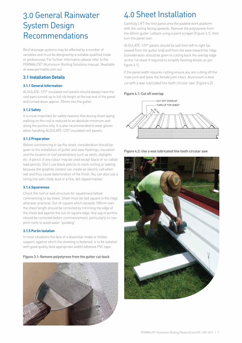
If the panel width requires cutting ensure you are cutting off the male joint and leave the female joint intact. Aluminium is best
cut with a wax-lubricated fine tooth circular saw. (Figure 4.2)
4.0 Sheet Installation
Figure 4.2: Use a wax lubricated fine tooth circular saw
Figure 4.1: Cut off overlap

8 | PERMALITE® Aluminium Roofing Panels ALSULATE-125® 2017
Figure 4.3: Turn up all roof pans at the top end of the panel
using the turn up tool
Figure 4.4: Turn down all the roof pans at the gutter end using
the turn down tool
4.2 Fixing
Prior to fixing the panel, move the soft covers along the support beam(s) or wall plate(s) to where the next panel will be installed to avoid panel damage. Secure the panel to the supporting beam(s) or wall(s) by screwing through every rib with RA195 14-12x195mm Hex head stainless steel screws with 16mm aluminium bonded washer and RA023 aluminium formed washers. (Figure. 4.5) Note: expansion fixing requirements for roof runs over 9m is set out at Section 7.3.
Figure 4.5: RA195 14-12x195mm hex head stainless steel
screw with 16mm aluminium bonded washer and RA023
aluminium formed washer
Figure 4.7: Avoid overtightening screws
Figure 4.6: Screw installationUnder no circumstances should the screw be over tightened to the point where the formed washer, or the bonded washer or the sheeting under the screw head, commence to distort.
Overlap
Overlap
4
6
4.1 Turn Up The Edge Of The Top Skin
Turn up all roof pans at the top end of the panel using a turn up tool. (Figure 4.3)
Turn down all the roof pans at the gutter end using a turn down tool. (Figure 4.4)
Place a soft cover over the top of the support beam(s) or wall plate(s) where the first panel will be installed to avoid damaging the panel surface.
Lift the panel into place ensuring the gutter/ cut back end is positioned at the lower end of the building and the male/ cut edge of the panel is positioned over the external edge of the structure. Square off the first panel and ensure the correct eave overhang measurements are achieved.

PERMALITE® Aluminium Roofing Panels ALSULATE-125® 2017 | 9
To install the second panel, position the panel into place with the overlap, then lower and push into the previously installed panel engaging the male and female joint. (Figure 5.1, 5.3 & 5.4) The ceiling connections should be neat with a consistent join line.
Fix panels in place following previous steps. Ensure panels are held tight together whilst fixing to maintain the neat consistent join line.
Using RA018 12g x 20 Hex Head stainless steel stitching screws with bonded aluminium washer, secure the overlap of the top skin. The fasteners are placed in the centre of the rib crest and at equal spacing’s between purlins but not exceeding 500mm. (Figure 5.2) When installing the fasteners, place one foot on the overlapping ribs to ensure they are firmly together.
Note: Panels should interlock with general ease, if you have any concerns/difficulties connecting the panels call your local sales representative immediately before proceeding.
Figure 5.1: Typical ALSULATE-125® panel laying detail
Figure 5.3 ALSULATE-125® panels before joining Figure 5.4 ALSULATE-125® panels after joining
Overlap
RA018 Stitching screw@ 500mm max. centres
Figure 5.2: Typical side lap details
5.0 Prepare The Remaining Panels As Per Previous Steps

10 | PERMALITE® Aluminium Roofing Panels ALSULATE-125® 2017
Install remaining panels following previous steps.
If your last panel requires cutting follow previous steps ensuring to cut off the opposite side you previously cut, and turn up the cut edge of the top sheet. (Figure 6.1)
After all panels are fitted install flashings, gutter, downpipe etc.
Common flashings and fixing details are shown in Section 8.
Figure 6.2: Z Flashing with gutter clips
Figure 6.1 Turn up the edge of the top skin
6.0 Last Panel Installation

PERMALITE® Aluminium Roofing Panels ALSULATE-125® 2017 | 11
7.1 Post Painting
Manual post painting is generally not recommended. Where there is no other option, we advise the following:
Flashings which are to be painted by the installer should first be washed with household detergent and dried. The flashing is then painted with an etch primer and finally brush painted with the colour coat.
Standard colours may be obtained on enquiry to major paint manufacturers. Touch up of scratched pre-painted sheet should be by brush only. Spray paints may fade prematurely.
7.2 Sealants
Silicone sealants used with aluminium sheeting must be neutral cure, however in some roofing applications a non-curing sealant may be required (Please refer to Lysaght for advice).
Neutral-cure silicone sealants have good adhesion to the clean surface of all our roofing and walling and are water resistant and non-corrosive.
7.3 Expansion Fixing Considerations
The PERMALITE® Positive Fix System provides for thermal expansion of the roofing sheet by “hard” fixing at the top of the sheet slope with “expansion” fixing being used to accommodate expansion towards the lower end of the sheet slope. For both types of fastening the screw should be screwed down until it presses on the washer with a medium pressure as shown at Figure 4.6.
7.4 Types of Pierced Fixings
7.4.1 Hard Fixing
“Hard” fixing is used where sheet lengths are such that thermal expansion in not a significant issue i.e. 9m or less.
A 6mm to 6.5mm diameter hole should be drilled through the upper sheet, EPS Foam and ceiling sheet prior to installation of the RA195 / RA023 fastener assembly. Pilot holes may also be needed into support members as per Table 7.1.
7.4.2 Expansion Fixing
For roof lengths in excess of 9m, “Hard” fixing is used for the first 9m from the ridge or skillion head. Expansion fixing is used for the remainder of the sheet length and follows the same procedure as hard fixing with the exception that the hole in the rib crest is slotted after drilling the tapping hole, using tool RA165.(Figure 7.1) A 10mm hole is then drilled through the ceiling sheet. (On large projects contact your Lysaght sales representative regarding use of this tool RA165).
Note that for expansion fixing, a rubber washer with an elongated hole and Teflon facing on one side is used. This washer must be installed with the Teflon side facing up toward the head of the screw.
Wall sheets should be rib hard fixed in the same way as roof cladding.
Long lengths of flashings may be “Hard” fixed. However in regions of high temperature variations it is advisable to consider expanding sheeting holes to 7mm for flashings in both roofing and wall sheeting applications.
Figure 7.1 PERMALITE® positive fix fastening system
ScrewBonded washer
Formed washer
Slotting tool
SlotTeflon side up
Hard fixed Expansion fixed
Expansion fixed
Rib seal6mmOpre-drilledhole
10O hole
RA165 Slotting tool
7.0 Other Installation Information
Table 7.1 Pilot hole diameter (mm) - Support structure metal thickness
FastenerAluminium Steel
Timber>3.0 to 6.0mm 0.42 to 1.49mm 1.5-5mm 5.0-15mm
304 GradeStainless Steel
RA19514-12 x195 Teks® self drilling screw
Self-Drilling Not Suitable Self-Drilling 5.7 Not Suitable
12 | PERMALITE® Aluminium Roofing Panels ALSULATE-125® 2017
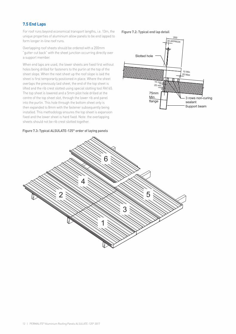
7.5 End Laps
For roof runs beyond economical transport lengths, i.e. 13m, the unique properties of aluminium allow panels to be end lapped to form longer in-line roof runs.
Overlapping roof sheets should be ordered with a 200mm “gutter cut back” with the sheet junction occurring directly over a support member.
When end laps are used, the lower sheets are fixed first without holes being drilled for fasteners to the purlin at the top of the sheet slope. When the next sheet up the roof slope is laid the sheet is first temporarily positioned in place. Where the sheet overlaps the previously laid sheet, the end of the top sheet is lifted and the rib crest slotted using special slotting tool RA165. The top sheet is lowered and a 5mm pilot hole drilled at the centre of the top sheet slot, through the lower rib and panel into the purlin. This hole through the bottom sheet only is then expanded to 8mm with the fastener subsequently being installed. This methodology ensures the top sheet is expansion fixed and the lower sheet is hard fixed. Note: the overlapping sheets should not be rib crest slotted together.
Slotted hole
Support beam
3 rows non-curing sealant
75mm Min.flange
Figure 7.2: Typical end lap detail
Figure 7.3: Typical ALSULATE-125® order of laying panels

PERMALITE® Aluminium Roofing Panels ALSULATE-125® 2017 | 13
8.0 ALSULATE-125® System Components
1000mm cover width333mm pitch
Pan
el h
eigh
t
Rib
hei
ght
16mm bonded washer16mm bondedwasher
RA195 - 14-14x195stainless steel self drilling screw
RA018 - 12-11x20stainless steel stitching screw
RA023 aluminium formed washer
Either RA036 EPDM flat washer
Or RA033 EPDM/Teflon®Flat washer with slot
4.8mm Al/Al blind rivet
4.8mm Al/Al structuralBulbtite® rivet
8.1 Sheeting
The 1m cover width panel provides an economical cover solution.
It is manufactured from 5251 H38 Marine grade 0.7mm thick aluminium top and bottom skins with a 125mm EPS foam core.
The outer profiled skin is available in GULL GREY®.
The prefinished internal skin is provided with an attractive smooth finish in GLACIER WHITE®
Customised colours are also available to suit your project needs, subject to minimum order quantities and extended lead times.
8.2 Fixings
RA195mm x 14g 304SS screws together with aluminium washers and EPDM the seal combine to ensure maximum performance in corrosive environments.
Figure 8.1: Typical ALSULATE-125® detail
Figure 8.2: Typical ALSULATE-125® panel fixings
8.3 Skillion Ridge End Flashing
Fixed with stitching screws @ max 333mm centres (every rib) to topside, and All aluminium blind rivets @ 400mm centres to underside.
Figure 8.3: Skillion ridge end flashing
Typical end cap flashing detail
Profiled top skin
Bottom skin
Support beam withisolation tape over
Al/ Al blind rivet
Foam
RA018 stitching screw0.9mm BMT typicalaluminium end capflashing

14 | PERMALITE® Aluminium Roofing Panels ALSULATE-125® 2017
8.5 Ridge Flashing
Fixed with RA195mm x 14g 304SS screws combined with aluminium washers and EPDM seal every rib topside into ridge supports.
0.9mm BMT typical aluminiumridge flashing
RA195 screwProfiled top skin
Bottom skin
Foam
Support beam withisolation tape over
0.9mm BMT typicalaluminium ridge under flashing fixed with Al/Al blindrivets @ 400 max. centres
(2 x roof pitch)(2 x roof pitch)
Figure 8.5: Typical aluminium ridge flashing detail
Typical aluminium ridge flashing detailTypical aluminium ridge under flashing detail
8.4 Barge Capping
Fixed with RA018 12 x 20mm stitching screws @ 400mm centres topside, and all aluminium blind rivets @ 400mm centres underside.
Variable
Typical barge cap flashing detail
250 micronisolation tape
Profiled top skin
AL/AL Blind rivet
RA018 Stitching screw
0.9 BMT typical aluminiumbarge capping
Foam
Bottom skinSupport beam withisolation tape over
Figure 8.4: Typical barge cap flashing detail with overhang

PERMALITE® Aluminium Roofing Panels ALSULATE-125® 2017 | 15
8.6 Gutter Connection Detail
Fixed with all aluminium blind rivets two off @ every pan top sheet, with neutral cure silicone sealant.
Figure 8.6: Typical gutter details
Figure 8.7: Typical Z-fascia detail
RA195 Screw
Profiled top skin4.8mm Al/Al blind rivets fixedat 2 off every pan with neutral cure silicone sealant
4.8mm Al/Al blind rivets fixedat 400mm max. centres
Aluminium slotted high front gutter
External gutter bracket fixed withAL/AL structural Bulbtite rivets
1.2mm BMT aluminium ‘Z’ fascia flashing
Support beam withisolation tape over

For more information visit www.permalite.com.auOr call toll free 1300 850 389
BLUESCOPE, LYSAGHT, PERMALITE, ALSULATE-125, ZINCALUME and COLORBOND are registered trademarks of BlueScope Steel Limited, ABN 16 000 011 058. Bulbtite®, Tek® and Roofzips® are registered trademarks of ITW Buildex. 9
3
20
07
5
08
18
29
LYP0
009
03/1
7
Product Descriptions
All descriptions, specifications, illustrations, drawings, data,
dimensions and weights contained this catalogue, all technical
literature and websites containing information from BlueScope are
approximations only.
They are intended by BlueScope to be a general description for
information and identification purposes and do not create a sale by
description. BlueScope reserves the right at any time to:
(a) supply Goods with such minor modifications from its drawings and
specifications as it sees fit; and
(b) alter specifications shown in its promotional literature to reflect
changes made after the date of such publication.
Disclaimer, warranties and limitation of liability
Terms and conditions of sale available at www.permalite.com.au.
Except to the extent to which liability may not lawfully be excluded or
limited, BlueScope Limited will not be under or incur any liability to you
for any direct or indirect loss or damage (including, without limitation,
consequential loss or damage such as loss of profit or anticipated
profit, loss of use, damage to goodwill and loss due to delay) however
caused (including, without limitation, breach of contract, negligence
and/or breach of statute), which you may suffer or incur in connection
with this publication.
© Copyright BlueScope Limited 16 March 2017