Embed Size (px)
Citation preview
Draft Sri Lanka Standard
SPECIFICATION FOR ALUMINIUM/ZINC ALLOY
COATED STEEL SHEETS FOR ROOFING AND CLADDING
SLS ………. : 2018
Gr.
Copyright Reserved
SRI LANKA STANDARDS INSTITUTION
No. 17, Victoria Place,
Elvitigala Mawatha,
Colombo 08
SRI LANKA
i
CONTENTS
FOREWORD ............................................................................................................................. 1
1 SCOPE ............................................................................................................................... 1
2 REFERENCES ................................................................................................................... 1
3 DEFINITIONS ................................................................................................................... 2
4 MANUFACTURE ............................................................................................................. 3
Base metal sheet .......................................................................................................... 3
Metallic coating ........................................................................................................... 3
Organic coating ............................................................................................................ 3
5 REQUIREMENTS ............................................................................................................. 5
General requirements ................................................................................................... 5
Sheet profile and dimensional requirements ............................................................... 6
Performance requirements (for pre-painted sheets) ..................................................... 8
Coating requirements ................................................................................................... 9
Mechanical requirements ........................................................................................... 10
6 TEST METHODS ............................................................................................................ 10
Determination of chemical composition .................................................................... 10
Determination of appearance of finished profiled sheet ............................................ 10
Determination of dimensions of the profile ............................................................... 10
Determination of dimensions of the sheet ................................................................. 11
Determination of performance ................................................................................... 12
6.7 Determination of tensile properties ........................................................................... 16
7 MARKING ....................................................................................................................... 16
8 PACKAGING, TRANSPORTATION AND STORAGE ............................................... 17
9 SAMPLING ..................................................................................................................... 17
10 COMPLIANCE OF A LOT ............................................................................................ 17
LIST OF TABLES
TABLE 1- Chemical composition .............................................................................................. 5
TABLE 2 – Aluminium - Zinc alloy coating requirements ....................................................... 7
TABLE 3 - Requirements of the minimum total organic film thickness ................................... 9
TABLE 4 – Mechanical properties of structural quality steel sheet ........................................ 10
TABLE A.1 – Scale of sampling ............................................................................................. 18
LIST OF FIGURES
FIGURE 1 : Depth of profile .................................................................................................... 19
FIGURE 2 : Depth of stiffeners ............................................................................................... 19
FIGURE 3 : Pitch ..................................................................................................................... 19
FIGURE 4 : Width of crown and valley .................................................................................. 20
FIGURE 5 : Radius of bends .................................................................................................... 20
LIST OF APPENDICES
APPENDIX A (Normative) SAMPLING SCHEME ............................................................... 18
APPENDIX B (Informative) TYPICAL PROFILE CONFIGURATIONS ............................. 19
APPENDIX C (Normative) MORTAR RESISTANCE TEST ................................................ 21
1
Draft Sri Lanka Standard
SPECIFICATION FOR ALUMINIUM/ZINC ALLOY
COATED STEEL SHEETS FOR ROOFING AND CLADDING
FOREWORD
This Standard was approved by the Sectoral Committee on Building and Construction
Materials and was authorized for adoption and publication as a Sri Lanka Standard by the
Council of the Sri Lanka Standards Institution on 2018 - … - …..
Aluminium/Zinc alloy coated metal roofing and wall cladding sheets are commonly used in
Sri Lanka for surfaces exposed to weather, such as roofs and wall cladding of industrial,
institutional, commercial and residential buildings. These sheets have many advantages, such
as lightness, ease and quickness of installation, durability, long service life, better security and
choice of aesthetically pleasing colours. Thus there is a strong need to introduce this national
standard.
Guidelines for the determination of compliance of a lot with the requirements of this standard
based on statistical sampling and inspection are given in Appendix A.
For the purpose of deciding whether a particular requirement of this standard is complied
with, the final value, observed or calculated, expressing the result of a test or an analysis shall
be rounded off in accordance with SLS 102. The number of significant figures to be retained
in the rounded off value shall be the same as that of the specified value in this standard.
In the preparation of this standard the assistance derived from the publications of the
American Society for Testing & Materials, International Organization for Standardization,
Singapore Institute of Standards & Industrial Research and Standards Australia are gratefully
acknowledged.
1 SCOPE
This Sri Lanka Standard specifies requirements for aluminium/zinc alloy coated steel sheets,
intended to be fabricated for use in the building industry for exterior applications such as
roofing, wall cladding and awnings.
2 REFERENCES
ISO 4628-1 Paints and varnishes - Designation system of appearance of coatings
ISO 6892-1 Tensile testing of metallic materials
ISO 17925 Zinc and/or aluminium based coatings on steel -- Coating mass per unit area
and chemical composition -- Gravimetry, inductively coupled plasma atomic
emission spectrometry and flame atomic absorption spectrometry
ISO 19272 Low alloyed steel - C, Si, Mn, P, S, Cr, Ni, Al, Ti and Cu - Glow discharge
optical emission spectrometry (routine method)
SLS ISO 3210 Anodizing of aluminium and its alloys - Quality of sealed anodic oxidation
coatings.
SLS ISO 9227 Corrosion tests in artificial atmospheres - Salt spray tests.
SLS ISO 9364 Continuous hot-dip aluminium/zinc coated steel sheet of commercial
drawing and structural qualities
2
SLS 107 Ordinary Portland cement
SLS 428 Random sampling method.
SLS 552 Building Lime
SLS 614 Potable water
SLS 994 Metallic materials- Bend test (ISO 7438)
SLS 1256/15 Methods of test for paints & varnishes Part 15: Determination of film
thickness ( ISO 2808)
SLS 1256/20 Section 1
Paints and varnishes - Scratch test – Constant loading ( ISO 1518-1)
SLS 1256/22 Paints and varnishes - Cross-cut test ( ISO 2409)
SLS 1256/27 Paints and varnishes - Resistance to liquids. ( ISO 2812-1)
SLS 1256/29 Paints and varnishes – Bend test (cylindrical mandrel) ( ISO 1519)
SLS 1256/31 Paints and varnishes – Determination of specular gloss of non-metallic paint
films at 20o, 60o and 85o. ( ISO 2813)
SLS 1256/32 Paints and varnishes – Evaluation of degradation of coatings-Designation of
quantity and size of defects, and of intensity of uniform changes in
appearance- Part 2: Assessment of degree of blistering ( ISO 4628/2)
SLS 1256/33 Paints and varnishes – Determination of resistance to humidity- Part 1:
Continuous condensation ( ISO 6270/1)
SLS 1256/34 Paints and varnishes – Rapid-deformation (impact resistance) tests- Part 1:
Falling-weight test, large area indenter ( ISO 6272/1)
SLS 1256/35 Paints and varnishes – Rapid-deformation (impact resistance) tests- Part 2:
Falling-weight test, small area indenter. ( ISO 6272/2)
SLS 1256/36 Paints and varnishes – Determination of film hardness by pencil test ( ISO
15184)
SLS 1256/37 Paints and varnishes – T-bend test (ISO 17132)
3 DEFINITIONS
For the purpose of this standard the following definitions shall apply.
base metal thickness: Thickness of the substrate excluding metallic coating.
coat: A continuous layer of product resulting from single application of primer,
top coat or wash coat.
coating mass: The total mass of metallic coating per unit area on both faces of the
product in g/m2.
dry film thickness: The thickness of organic coating.
lot: All the sheets of the same steel grade and the same coating designation, in any
consignment having the same width and profile and cut to a specified length and
belonging to one batch or manufacture or supply.
metallic coating: An aluminium/zinc alloy coating
organic coating: The paint film of the pre-painted metal product
3
percentage elongation after fracture, A: Permanent elongation of the gauge length
expressed as a percentage of the original gauge length.
pre painted metal product: A substrate which is painted before fabrication into
profiled sheets.
primer: The first complete layer of paint of a coating system applied to substrate.
profiled sheet: component whose cross-section consists of corrugation.
0.2 % proof strength: Stress at which the plastic extension is equal to 0.2 % of the
extensometer gauge length.
reverse face: Opposite face of the top face.
structural quality steel : Material intended for application, where mechanical
properties are specified.
substrate: A metallic coated sheet steel (excluding organic coating).
tensile strength: Stress corresponding to maximum force
test panel: The rectangular panel with specific dimensions specified by the test method,
which separated from the sheet intended for testing of particular parameter.
test piece: The test piece with specific shape and dimensions specified by the test method,
which is separated from the sheet intended for testing of particular parameter.
total coated thickness: The thickness of substrate inclusive of metallic coating.
top face: Face normally exposed to the weather.
upper yield strength: Maximum value of stress prior to the first decrease in force
4 MANUFACTURE
Base metal sheet
Base metal shall be structural quality steel of Grade 320, 350 or 550 as given in
SLS ISO 9364.
Metallic coating
Metallic coating on steel sheet shall be 55 % aluminium/zinc (Al/Zn) alloy, corresponding to
coating designation of AZ150 or AZ200 as given in SLS ISO 9364.
Organic coating
Where the organic coating is applied, it shall consist of a primer and a top-coat on the top
(exposed) face and as optional wash coat on the reverse (unexposed) face. Additionally the
top and reverse face may be provided with additional coats, which can be 2, 3 or 4 coats and
4
the actual coating system may vary from manufacturer to manufacturer, depending on the
specific performance requirements such as gloss, flexibility, fading resistance, chalking and
resistance to cracking at bends, abrasion resistance, dirt retention, and resistance to varying
atmospheric conditions.
Primer
The purpose of primer is to serve as the bond between the substrate and the top coat and to
offer added corrosion protection for the substrate. The minimum dry film thickness of primer
shall be 5 μm.
When a primer is used it must be compatible with both the conversion coating and the top
coat in order to ensure optimum properties of the coating system. For this reason the type of
primer is usually not specified by the purchaser but generally selected by the sheet producer
for optimum compatibility and for appropriateness to the service environment. Typical
primers are:
a) Acrylic - resin with good flexibility;
b) Epoxy - resin with good flexibility;
c) Polyester - resin with improved flexibility; and
d) Polyurethane - coating with good flexibility.
Top coats
Top coat provides colour and durability and also acts as protection against atmospheric
corrosion. Selection of coating system is based on the performance or appearance
requirements specified. The minimum total dry film thickness of top coats shall be 20 μm.
The top coat is applied to the exposed surface of the sheet. However the same coating may be
applied on the reverse face. The coating that is applied to the reverse face of metallic coated
steel substrate is usually a wash coat or reverse coat.
Typical top coats are:
a) Acrylic - unplasticized coating with flexibility, available in semi-gloss
finishes, particularly suited for external use;
b) Alkyd - coating with formability and preferably for indoor applications;
c) Fluorocarbon - durable coatings for colour retention against ultra-violet and
offers flexibility;
d) Plastisol - offers resistance against corrosion but relatively low resistance
against ultra-violet and available limited colour range;
e) Polyester - coating with flexibility and hardness characteristic and can be
supplied in gloss, semi-gloss finishes suitable for internal and
external use;
f) Polyurethane - coating with flexibility and decorative properties and can be
supplied in gloss and semi-gloss finishes suitable for external
use;
a) Silicone modified - coating with flexibility available in semi-gloss finishes
polyester preferably for external use; and
h) Silicone polyester - offers flexibility and slightly better weather resistance ability
than polyester coating.
5
Wash coats
The wash coat applied to the reverse face of the sheet may be pigmented or clear. The wash
coat may be specified with the same material and thickness as the top coat system, otherwise
the minimum dry film thickness of wash coat shall be 5 μm.
5 REQUIREMENTS
General requirements
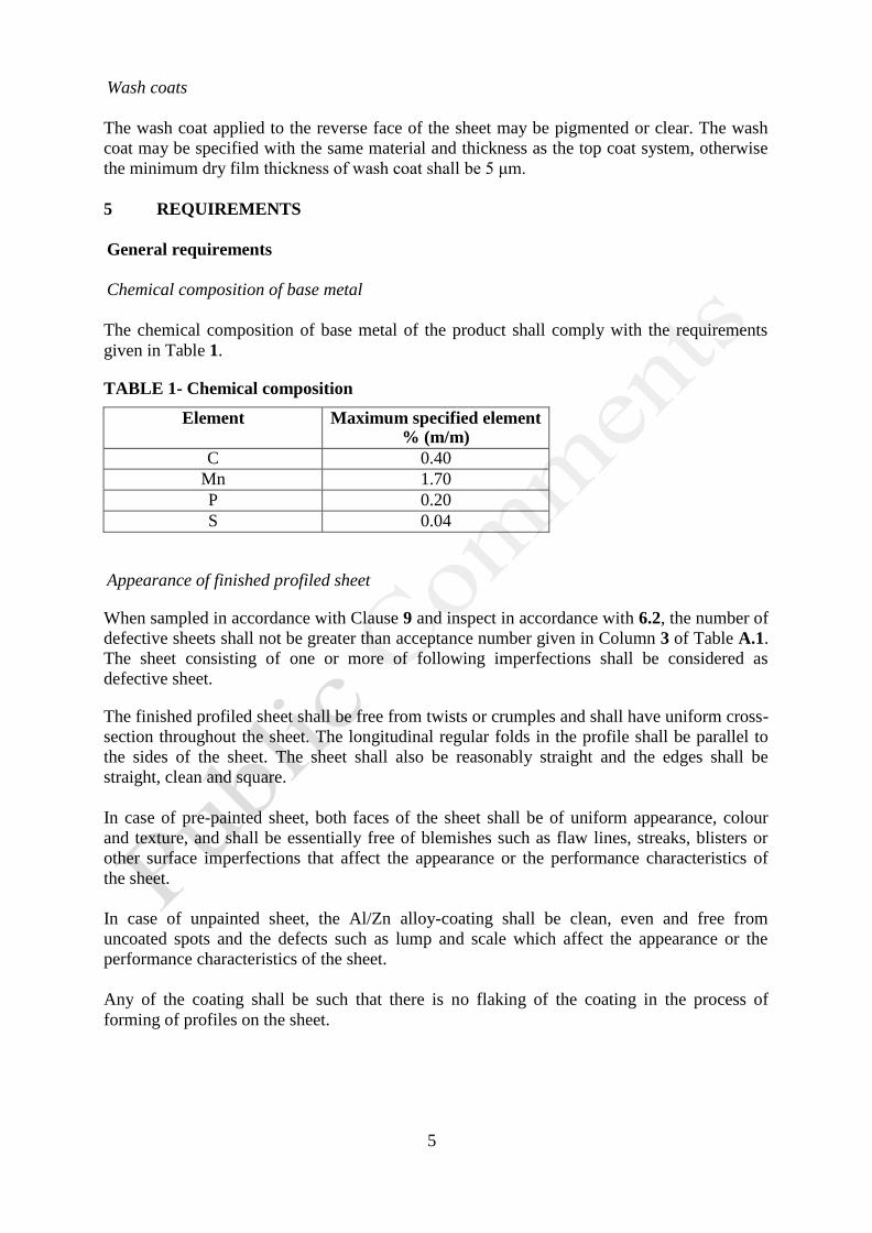
Chemical composition of base metal
The chemical composition of base metal of the product shall comply with the requirements
given in Table 1.
TABLE 1- Chemical composition
Element Maximum specified element % (m/m)
C 0.40
Mn 1.70
P 0.20
S 0.04
Appearance of finished profiled sheet
When sampled in accordance with Clause 9 and inspect in accordance with 6.2, the number of
defective sheets shall not be greater than acceptance number given in Column 3 of Table A.1.
The sheet consisting of one or more of following imperfections shall be considered as
defective sheet.
The finished profiled sheet shall be free from twists or crumples and shall have uniform cross-
section throughout the sheet. The longitudinal regular folds in the profile shall be parallel to
the sides of the sheet. The sheet shall also be reasonably straight and the edges shall be
straight, clean and square.
In case of pre-painted sheet, both faces of the sheet shall be of uniform appearance, colour
and texture, and shall be essentially free of blemishes such as flaw lines, streaks, blisters or
other surface imperfections that affect the appearance or the performance characteristics of
the sheet.
In case of unpainted sheet, the Al/Zn alloy-coating shall be clean, even and free from
uncoated spots and the defects such as lump and scale which affect the appearance or the
performance characteristics of the sheet.
Any of the coating shall be such that there is no flaking of the coating in the process of
forming of profiles on the sheet.
6
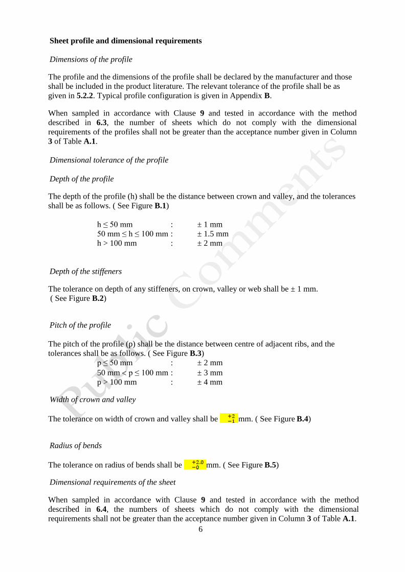
Sheet profile and dimensional requirements
Dimensions of the profile
The profile and the dimensions of the profile shall be declared by the manufacturer and those
shall be included in the product literature. The relevant tolerance of the profile shall be as
given in 5.2.2. Typical profile configuration is given in Appendix B.
When sampled in accordance with Clause 9 and tested in accordance with the method
described in 6.3, the number of sheets which do not comply with the dimensional
requirements of the profiles shall not be greater than the acceptance number given in Column
3 of Table A.1.
Dimensional tolerance of the profile
Depth of the profile
The depth of the profile (h) shall be the distance between crown and valley, and the tolerances
shall be as follows. ( See Figure B.1)
h ≤ 50 mm : ± 1 mm
50 mm ≤ h ≤ 100 mm : ± 1.5 mm
h > 100 mm : ± 2 mm
Depth of the stiffeners
The tolerance on depth of any stiffeners, on crown, valley or web shall be ± 1 mm.
( See Figure B.2)
Pitch of the profile
The pitch of the profile (p) shall be the distance between centre of adjacent ribs, and the
tolerances shall be as follows. ( See Figure B.3)
p ≤ 50 mm : ± 2 mm
50 mm p ≤ 100 mm : ± 3 mm
p > 100 mm : ± 4 mm
Width of crown and valley
The tolerance on width of crown and valley shall be mm. ( See Figure B.4)
Radius of bends
The tolerance on radius of bends shall be mm. ( See Figure B.5)
Dimensional requirements of the sheet
When sampled in accordance with Clause 9 and tested in accordance with the method
described in 6.4, the numbers of sheets which do not comply with the dimensional
requirements shall not be greater than the acceptance number given in Column 3 of Table A.1.
7
Length of the sheet
Length of the sheet shall be as agreed with the customer and the tolerance shall be as given in
5.2.4. The average length of each sheet as tested in accordance with the method described in
6.4.1 shall conform to the requirement agreed with the customer.
Effective width of the sheet
Effective width shall be as declared by the manufacturer and the tolerance shall be as given in
5.2.4.The average effective width of each sheet as tested in accordance with the method
described in 6.4.2 shall conform to the requirement declared by the manufacturer.
Thickness of the sheet
The base metal thickness shall be specified as the thickness of the finished profiled sheet. The
thickness of the finished profiled sheet shall be declared by the manufacturer and the
minimum base metal thicknesses for different applications as a guideline are given in
Appendix C. The average total coated thickness shall be the base metal thickness plus
equivalent coating thickness given in Table 2 and the tolerance shall be as given in 5.2.4.The
average total coated thickness of each sheet as tested in accordance with the method described
in 6.4.3 shall conform to the requirement declared by the manufacturer.
Deviation from squareness
The deviation of squareness of each sheet from the theoretical straight line as determined in
accordance with the method described in 6.4.5 shall not exceed 1.05 % of effective width.
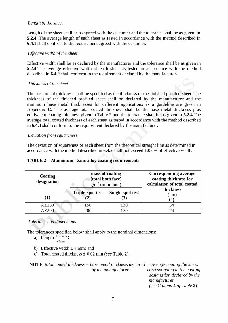
TABLE 2 – Aluminium - Zinc alloy coating requirements
Coating
designation
(1)
mass of coating
(total both face)
g/m2 (minimum)
Corresponding average
coating thickness for
calculation of total coated
thickness
(μm) (4)
Triple-spot test
(2)
Single-spot test
(3)
AZ150 150 130 54
AZ200 200 170 74
Tolerances on dimensions
The tolerances specified below shall apply to the nominal dimensions:
a) Length + 10 mm ; - 3mm
b) Effective width 4 mm; and
c) Total coated thickness 0.02 mm (see Table 2).
NOTE: total coated thickness = base metal thickness declared + average coating thickness
by the manufacturer corresponding to the coating
designation declared by the
manufacturer
(see Column 4 of Table 2)
8
Performance requirements (for pre-painted sheets)
The tests under performance requirements shall be carried out only for the pre-painted sheets.
Specular gloss
When sampled in accordance with Clause 9 and tested in accordance with the method
described 6.5.3, the mean value of specular gloss of top face of each sheet shall not exceed 30
units.
Rapid deformation (Impact resistance)
When sampled in accordance with Clause 9 and tested in accordance with the method
described in 6.5.4, the rapid deformation of organic paint coating on either face (top and
reverse) of each sheet shall satisfy the requirements specified in Clause 7.2 of SLS 1256/34
(ISO 6272-1)
Scratch resistance
When sampled in accordance with Clause 9 and tested in accordance with the method
described in 6.5.5, the scratch resistance of organic paint coating on either face of each sheet
shall satisfy the requirements specified in Clause 7.3 of SLS 1256/20 Section 1 (ISO 1518-1).
Cross-cut adhesion
When sampled in accordance with Clause 9 and tested in accordance with the method
described in 6.5.6, the cross-cut adhesion of organic paint coating on either face of each sheet,
shall comply with the Classification 0 as specified in Table 1 of SLS 1256/22.( ISO 2409)
Humidity resistance
When sampled in accordance with Clause 9 and tested in accordance with the method
described in 6.5.7, the humidity resistance of organic paint coating on either face of each
sheet shall satisfy the requirements as specified in Clause 9 of SLS 1256/33 (ISO 6270-1).
Acid resistance
When sampled in accordance with Clause 9 and tested in accordance with the method
described in 6.5.8, no blistering shall be observed on either face. Intensity of colour change on
either face shall be not worse than Rating 1 of ISO 4628-1.
Corrosion resistance
When sampled in accordance with Clause 9 and tested in accordance with the method
described in 6.5.9, the corrosion resistance of organic paint coating on either face of each
sheet shall satisfy the requirements as specified in Clause 11 of SLS ISO 9227.
Mortar resistance
When sampled in accordance with Clause 9 and tested in accordance with the method
described in 6.5.10, the mortar resistance of organic paint coating on either face of each sheet
shall satisfy the following requirements.
9
a) the mortar shall dislodge easily from the panel and any residue can be removed with damp
cloth; and
b) shall not show loss of film adhesion or change in appearance of the coating due to the
mortar patch.
Coating requirements
Metallic coating
Total coating mass on both faces
When sampled in accordance with Clause 9 and tested in accordance with the method
described in 6.6.1.1, the average coating mass on triple-spot and any determination on single-
spot of each sheet shall conform to the requirement given in Column 2 and 3 of Table 2
corresponding to the relevant coating designation.
Adhesion of metallic coating
When sampled in accordance with Clause 9 and tested in accordance with the method
described in 6.6.1.2, the adherence of metallic coating on either faces of each sheet sampled
shall comply with the following requirements.
Any test specimen shall show no flaking on outer (convex) surface of the bend. Flaking of the
coating within 7 mm from the edge shall not be a cause for rejection.
Organic paint coating
Film thickness of organic paint coating
When sampled in accordance with Clause 9 and tested in accordance with the method
described in 6.6.2.1, the film thickness of organic paint coating on either faces of each sheet
shall comply with the requirement given in Column 2 and 3 of Table 4 corresponding to the
relevant coating designation.
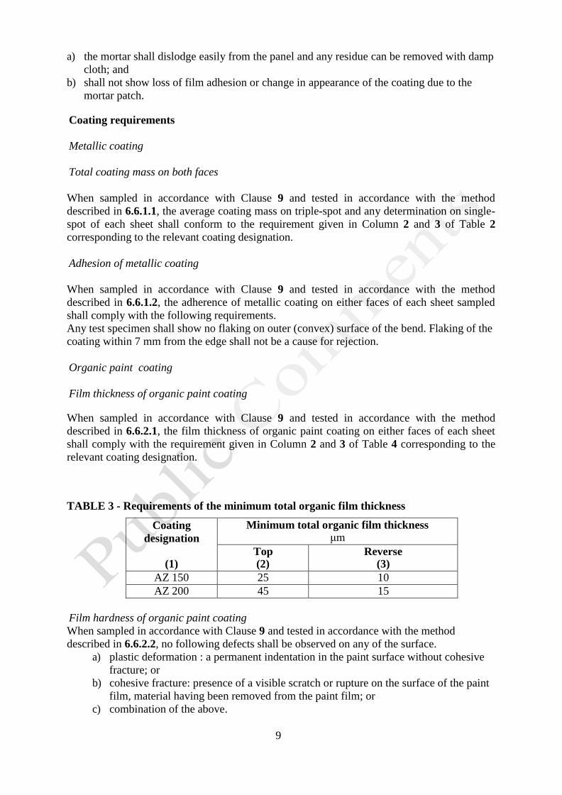
TABLE 3 - Requirements of the minimum total organic film thickness
Coating
designation
(1)
Minimum total organic film thickness μm
Top (2)
Reverse (3)
AZ 150 25 10
AZ 200 45 15
Film hardness of organic paint coating
When sampled in accordance with Clause 9 and tested in accordance with the method
described in 6.6.2.2, no following defects shall be observed on any of the surface.
a) plastic deformation : a permanent indentation in the paint surface without cohesive
fracture; or
b) cohesive fracture: presence of a visible scratch or rupture on the surface of the paint
film, material having been removed from the paint film; or
c) combination of the above.
10
Adhesion of organic paint coating
When sampled in accordance with Clause 9 and tested in accordance with the method
described in 6.6.2.3, the adhesion of organic paint coating on either faces of each sheet shall
comply with the requirements specified in 8.4 of SLS 1256/37 (ISO 17132).
5.5 Mechanical requirements
5.5.1 Tensile properties
When sampled in accordance with Clause 9 and tested in accordance with the method
described in 6.7, the arithmetic mean of upper yield stress (ReH), tensile strength (Rm) and
percentage of elongation after fracture (A) shall comply with the requirements given in
Column 2, 3, 4 and 5 in Table 5 corresponding to the relevant grade of base metal.
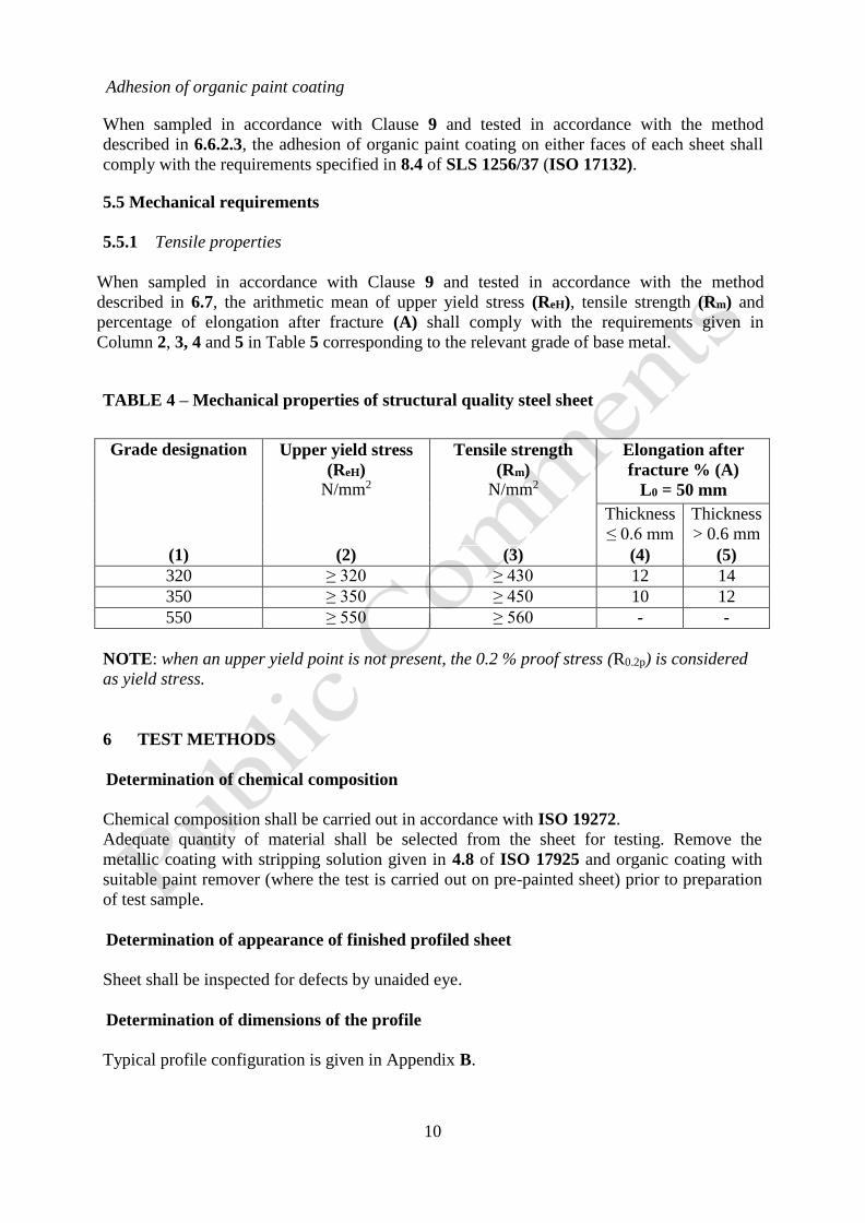
TABLE 4 – Mechanical properties of structural quality steel sheet
Grade designation Upper yield stress
(ReH)
N/mm2
Tensile strength
(Rm)
N/mm2
Elongation after
fracture % (A)
L0 = 50 mm
Thickness
≤ 0.6 mm
Thickness
> 0.6 mm
(1) (2) (3) (4) (5)
320 ≥ 320 ≥ 430 12 14
350 ≥ 350 ≥ 450 10 12
550 ≥ 550 ≥ 560 - -
NOTE: when an upper yield point is not present, the 0.2 % proof stress (R0.2p) is considered
as yield stress.
6 TEST METHODS
Determination of chemical composition
Chemical composition shall be carried out in accordance with ISO 19272.
Adequate quantity of material shall be selected from the sheet for testing. Remove the
metallic coating with stripping solution given in 4.8 of ISO 17925 and organic coating with
suitable paint remover (where the test is carried out on pre-painted sheet) prior to preparation
of test sample.
Determination of appearance of finished profiled sheet
Sheet shall be inspected for defects by unaided eye.
Determination of dimensions of the profile
Typical profile configuration is given in Appendix B.
11
Depth of the profile, depth of stiffeners, pitch of the profile, and width of crown and valley
Six measurements for each of the following dimensions of the sheet profile shall be measured
to the nearest 1 mm, at 200 mm from the edge of the sheet.
Depth of the profile
Depth of stiffeners
Pitch of the profile
Width of crown and valley
Report the individual measurements for each dimension.
Radius of bends
Six measurements of inner radius shall be measured with radius gauge to the nearest 0.25 mm
at a distance of 200 mm from the edge of the sheet and report individual measurements.
Determination of dimensions of the sheet
Length of the sheet
The sheet shall be laid in longitudinal direction on a flat surface, ensuring that the valleys of
profile are in contact with it.
Three length measurements shall be taken , one in the middle and other two at approximately
50 mm from the sides avoiding folded corners.
Use the rigged steel tape or suitable measuring device to measure the length of sheet to the
accuracy of 1 mm. Calculate the arithmetic mean length of the sheet and report to the nearest
millimeter.
Effective width of the sheet
Two sheets shall be laid in transverse direction on the flat surface with lapping of adjacent
sides of the sheets, ensuring that the valleys of profiles are in contact with the surface.
For the sheets longer than 1 m, take three effective width measurements, one in the middle
and other two at approximately 50 mm from the two ends. For the sheets of nominal length
equal to or shorter than 1 m, take two measurements, approximately 50 mm from two ends.
Use the steel ruler or suitable measuring device to measure the effective width of the sheet to
the accuracy of 1 mm. Calculate the arithmetic mean effective width of the sheet and report to
the nearest millimeter.
Total thickness of the sheet
Six measurements shall be taken with a metal sheet micrometer or other suitable measuring
device to an accuracy of 0.001 mm, approximately 15 mm from two ends of the sheet. All
measurements shall be taken from the plane areas of the sheet.
When the measurement is taken on pre-painted sheet, organic coating shall be removed.
Calculate the arithmetic mean of the total thickness of sheet and report to the nearest
0.01 mm.
Deviation from squareness
Deviation from squareness of the sheet end shall be measured at each corner to the nearest
1 mm with engineering square. Straightness of each arm of the engineering square shall not be
12
deviated by more than 0.3 mm per metre length. The angle between the arms of the
engineering square shall be /2 0.001 rad.
Calculate the percentage of deviation with reference to the effective width and report the
average of four measurements corresponding to the corners, to the nearest 0.1 %.
Determination of performance
Preparation of the test piece for determination of performance
Test region shall be at least 100 mm away from two ends and at least 50 mm away from two
edges of the sheet. The test area for the determination of performance requirements shall be
selected/prepared from the suitable plane area of the test region.
If practicable, test panels with dimensions of at least 150 mm x 100 mm shall be removed
from the test region and test panels shall be free from any defects. When the available plane
area is inadequate to cover any of the specified dimensions, the test panel shall be prepared
with maximum plane area that can be obtained.
Wherever required, two sets of test panels shall be prepared for testing of coatings on top and
reverse faces of the sheet. Care shall be taken to avoid any deformation or damage on coated
faces while preparing the test panel since those may affect the test results.
Number of test panels shall be as given in the test method.
Each test face shall be rinsed properly to remove any foreign matter adhered to the surface (if
any) before testing. If any chemical is used to clean the surface, it shall not affect the coating.
Conditioning atmosphere
Wherever specified, the test panels shall be conditioned immediately prior to the test at a
temperature of 27 2 0C and a relative humidity of 65 5 % for a minimum period of 16 h
and the tests shall be carried out at the same temperature and humidity conditions.
Specular gloss
Specular gloss shall be carried out in accordance with 10.2 of SLS 1256/31 (ISO 2813) with
the incident angle of 600. Report the mean value specular gloss to the nearest one unit.
Rapid deformation (Impact resistance)
Rapid deformation test shall be carried out in accordance with the “Pass/fail test (using
specified mass)” described in 7.2 of SLS 1256/34 (ISO 6272-1). The total mass of the falling
weight shall be 1000 10 g and falling height shall be 100 2 mm.
Two test panels shall be removed from the sheet as per 6.5.1 and independently tested for the
coating on top and reverse faces by applying five drops on each panel. Test panels shall be
conditioned in accordance with 6.5.2 prior to commencement of the test and test carried out at
the same conditions.
Report the test results for the coatings on both faces of sheet as per 7.2 of
SLS 1256/34 (ISO 6272-1).
13
Scratch resistance test
Scratch resistance test shall be carried out in accordance with the “Single specified load
(“pass/fail” test)” described in 7.3 of SLS 1256/20 Section 1 (ISO 1518-1). The test load
shall be 2000 5 g.
Two sets, each including two test panels shall be removed from the sheet as per 6.5.1 and
each set shall be independently tested for the coating on top and reverse faces. Test panels
shall be conditioned in accordance with 6.5.2 prior to commencement of the test and test
carried out at the same conditions.
Report the test results for the coatings on both faces of the sheet as per 7.3 of
SLS 1256/20 Section 1 (ISO 1518-1). .
Cross-cut adhesion
Cross-cut adhesion test shall be carried out in accordance with 6.2 or 6.3 of
SLS 1256/22 (ISO 2409) with the multi-blade cutting tool. The spacing of cutting edges of
the tool shall be 1 mm.
Two test panels shall be removed from the sheet as per 6.5.1 and shall be independently tested
for the coating on top and reverse faces. Test panels shall be conditioned in accordance with
6.5.2 prior to commencement of the test and test carried out at the same conditions. Test shall
be carried out for at least three different places on each panel.
Report the classification for the coatings on both faces of sheet as per Clause 8 of SLS
1256/22 (ISO 2409), when observed with an unaided eye.
Humidity resistance
Humidity resistance test shall be carried out in accordance with Clause 8 of SLS 1256/33
(ISO 6270-1). The temperature above the liquid face shall be maintained at 49 2 0C and the
test period shall be 1000 h.
Two sets, each including two test panels shall be removed from the sheet as per 6.5.1 and
shall be independently tested for the coating on top and reverse faces. One or more scribe
lines shall be marked on the test face of one panel of each set and the cut edges of all the
panels shall be properly sealed (e.g. with bee wax, silicone sealant, etc.) prior to performing
the test to prevent corrosion through edges. Test panels shall be conditioned in accordance
with 6.5.2 prior to commencement of the test.
Report the test results for the coatings on both faces of sheet as per the following
requirements.
Test condition Requirement
a) Face with scribe lines No blistering of organic coating or corrosion of base metal.
No loss of adhesion of organic coating
beyond 2 mm from the scribe line.
b) Face without scribe lines No blistering of organic coating or corrosion
of base metal.
Acid resistance
Acid resistance test shall be carried out in accordance with Method A – Single-phase liquid,
given in SLS 1256/27 (ISO 2812-1). Test solution shall be sulfuric acid solution, with a mass
14
fraction of 10 % sulfuric acid. The immersion depth shall be half of the test panel and the
duration of immersion shall be 48 hours.
One test panel shall be prepared from the sheet as per 6.5.1 and the cut edges of panel shall be
properly sealed with bee wax prior to testing. Test panel shall be conditioned in accordance
with 6.5.2 prior to commencement of the test.
Report the degree of blistering and any visual changes for top and reverse faces as per
SLS 1256/32 (ISO 4628-2) and ISO 4628-1.
Corrosion resistance
The corrosion resistance test shall be carried out in accordance with Neutral Salt Spray (NSS)
method given in SLS ISO 9227. The test periods for coating designation AZ 150 and AZ 200
shall be 1000 h and 2000 h respectively.
Two sets, each including three test panels shall be removed from the sheet as per 6.5.1 and
shall be independently tested for the coating on top and reverse faces. Scratch lines shall be
marked on the test surface of one panel of each set as per the C.4 of SLS ISO 9227. The cut
edges of these panels and other two panels selected from remaining panels shall be properly
sealed with paraffin wax or bee wax or any other appropriate material to prevent the
penetration of test solution through the cutting edges. Remaining panels in the set shall be
determined with unsealed cut edges. All the test panels shall be conditioned in accordance
with 6.5.2 prior to commencement of the test and shall be checked for the following
requirements.
Test conditions Requirements
a) Panels with sealed edges
1. Surface with scribe lines
2. Surface without scribe lines
No blistering of organic coating or corrosion
of base metal.
No loss of adhesion beyond 2 mm from the
scribe line
No blistering of organic coating or corrosion
of base metal.
b) Panels with unsealed edges
1. Surface without scribe lines and
assessed at distance of 25 mm beyond the
edges
Degree of blistering shall be less than or
equal to Quantity (density) 2 – 2(S3) as
specified in ISO 4628/2. No corrosion of base metal
Report the test results for the coatings on both faces of the sheet as per the given
requirements.
Mortar resistance
The test shall be carried out in accordance with Appendix C.
Two test panels shall be removed from the sheet as per 6.5.1 and shall be independently tested
for the coating on top and reverse faces. Test panels shall be conditioned in accordance with
6.5.2 prior to commencement of the test and test shall be carried out at same conditions.
Report the test results for the coatings on both faces as per C.6.
15
Determination of coating properties
Metallic coating
Coating mass
Coating mass and percentage of aluminium (if required) in the coating shall be tested in
accordance with ISO 17925.
Total coating mass on total both faces shall be determined on each test piece. Where the test
carried out on pre-painted sheet, organic coating shall be removed with non-corrosive paint
remover prior to commencement of the test.
Report the mass of coating on each determination (single spot) and the average of three
determinations (triple spot) to the nearest whole number.
Adhesion of metallic coating
Adhesion of metallic coating on grade 320 sheet shall be carried out in accordance with
SLS 994 (ISO 7438) with the angle of the bend 1800. Internal radius of the bend on sheet
shall be 3a, where “a” is the thickness of the sheet.
Four test strips, two from longitudinal direction and other two from transverse direction shall
be prepared in accordance with SLS 994 (ISO 7438) from the plane areas of the sheet and
shall be independently tested for the coating on both faces.
When the test is carried out on organic paint coated sheet, the organic paint coating on the test
strips shall be removed with non corrosive paint remover prior to commencement of the test.
Report the test results for the coatings on both faces of sheet.
Organic paint coating
Film thickness of organic paint coating
Organic film thickness shall be tested in accordance with any suitable method described in
Clause 5 of SLS 1256/15 (ISO 2808) except Eddy-current gauge.
Six measurements shall be taken for each face of the sheet to the accuracy of 1 m, from the
suitable plane areas of the sheet.
Calculate the arithmetic mean of the film thickness for each face of the sheet and report the
value to the nearest 1 m.
Film hardness of organic paint coating
Film hardness of organic paint coating shall be carried out in accordance with Clause 8 of
SLS 1256/36 (ISO 15184). The hardness of the pencil shall be HB (hard-black).
Two test panels shall be removed from the sheet as per 6.5.1 and shall be independently tested
for the coating on top and reverse faces. Test panels shall be conditioned in accordance with
6.5.2 prior to commencement of the test and test carried out at the same conditions. Tests shall
be carried out at least on three different places of each panel.
16
Report the test result for the top and reverse face of the sheet as per requirements given in
Clause 9 of SLS 1256/36 (ISO 15184).
6.6.2.3 Adhesion of organic paint coating
Adhesion of organic paint coating shall be carried out with T-bend test in accordance with
8.3.4 of SLS 1256/37 (ISO 17132) and specified number of T-bends shall be five (5T).
Two pairs of test pieces (strips) for each face shall be removed in accordance with
SLS 1256/37 (ISO 17132) from the plane areas of the sheet. Two pairs of the test pieces shall
be taken in the longitudinal direction and other two in the transverse direction of the sheet.
Report the test results for the top and reverse face of the sheet as per the requirements given in
8.4 of SLS 1256/37 (ISO 17132).
6.7 Determination of tensile properties
Tensile properties shall be tested in accordance with ISO 6892-1.
Two sets, one from longitudinal direction and other from transverse direction, each including
three tensile test pieces shall be prepared in accordance with Appendix B of ISO 6892-1 from
the plane area of the sheet.
When the test is carried out on pre-painted test piece, organic coating shall be removed on the
identified measuring points of test piece prior to measuring the thickness.
Arithmetic mean of the three determinations of the tensile property of either direction of the
sheet shall be calculated and report the individual results and mean value to the nearest whole
number.
7 MARKING
Each sheet shall be legibly and indelibly marked by any suitable method with the
following information:
a) The name or registered trade mark of the manufacturer or both;
b) Base metal thickness;
c) Grade of the base metal;
d) Coating designation; and
e) SLS mark if applicable (see back cover of the standard).
NOTE : Attention is drawn to certification facilities offered by SLSI, see the inside back
cover of this standard.
In addition each bundle of sheets shall carry a sticker/tag with the following information.
a) The application of the product (i.e. Roofing or Wall cladding);
b) The shape and dimensions of the profile or manufacturer’s corresponding code; and
c) The date of manufacture or batch number.
17
8 PACKAGING, TRANSPORTATION AND STORAGE
The product shall be suitably packed and supported during transportation to ensure minimum
structural stress induced on the material. Every precaution shall be taken against damage of
the paint coating during transportation and transfer.
The product shall be lifted directly and not dragged over rough surface or over each other.
Care shall also be taken to avoid dragging, cutting and forming tools over the surfaces of the
finished products.
On recommendation by the supplier and if deemed necessary by the purchaser, a temporary
transport protective film over the finished surface coating of the product may be specified in
the contract. The type of protective film to be used shall be recommended by the
manufacturer and easily removed immediately after installation. Proper on-site storage of
panels prior to installation is important in maintaining the integrity of the coating system.
Pallets should be placed off the ground and at a slight angle for effective drainage. If there is a
lengthy contact with moisture during storage prior to installation weather proof covers or the
equivalent may be used for keeping the pallets dry.
9 SAMPLING
Where the compliance of a lot to the requirements of this specification is to be assessed based
on statistical sampling and inspection, the sampling scheme given in Appendix A shall be
applied.
Where the compliance with this specification is to be assured based on manufacturer’s control
system coupled with type testing and check tests or any other procedures, appropriate
schemes of sampling and any other inspection procedures can be adopted
10 COMPLIANCE OF A LOT
Any lot, when sampled in accordance with Clause 9, fails to comply with any of the
requirements specified in Clause 5, shall be deemed not to comply with this standard.
18
APPENDIX A
(Normative)
SAMPLING SCHEME
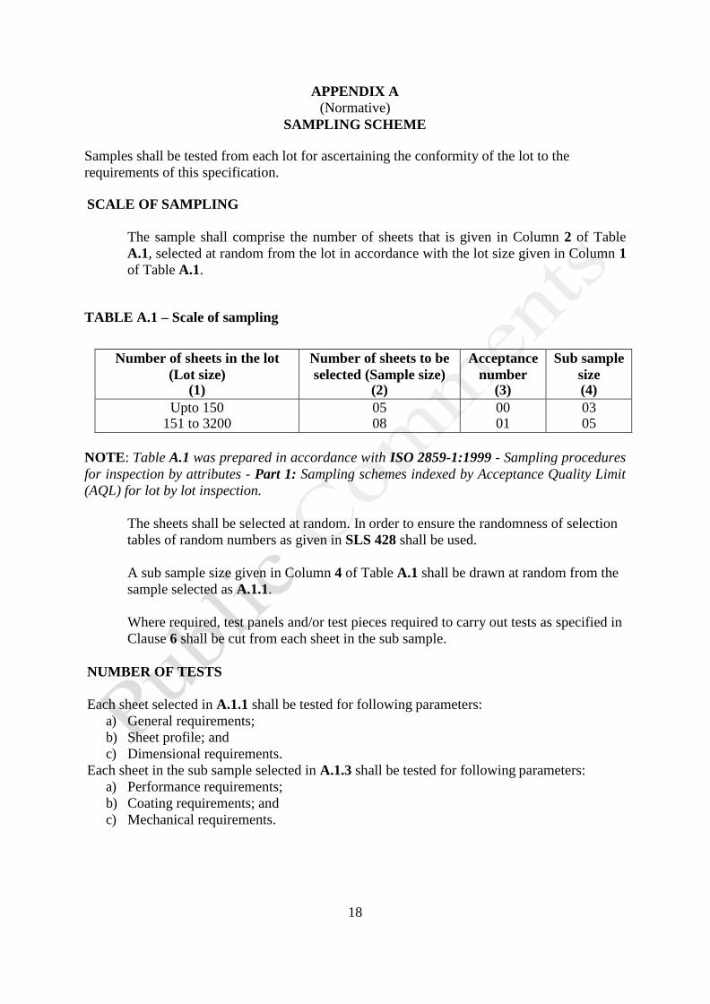
Samples shall be tested from each lot for ascertaining the conformity of the lot to the
requirements of this specification.
SCALE OF SAMPLING
The sample shall comprise the number of sheets that is given in Column 2 of Table
A.1, selected at random from the lot in accordance with the lot size given in Column 1
of Table A.1.
TABLE A.1 – Scale of sampling
Number of sheets in the lot
(Lot size) (1)
Number of sheets to be
selected (Sample size) (2)
Acceptance
number (3)
Sub sample
size (4)
Upto 150 151 to 3200
05 08
00 01
03 05
NOTE: Table A.1 was prepared in accordance with ISO 2859-1:1999 - Sampling procedures
for inspection by attributes - Part 1: Sampling schemes indexed by Acceptance Quality Limit
(AQL) for lot by lot inspection.
The sheets shall be selected at random. In order to ensure the randomness of selection
tables of random numbers as given in SLS 428 shall be used.
A sub sample size given in Column 4 of Table A.1 shall be drawn at random from the
sample selected as A.1.1.
Where required, test panels and/or test pieces required to carry out tests as specified in
Clause 6 shall be cut from each sheet in the sub sample.
NUMBER OF TESTS
Each sheet selected in A.1.1 shall be tested for following parameters:
a) General requirements;
b) Sheet profile; and
c) Dimensional requirements.
Each sheet in the sub sample selected in A.1.3 shall be tested for following parameters:
a) Performance requirements;
b) Coating requirements; and
c) Mechanical requirements.
19
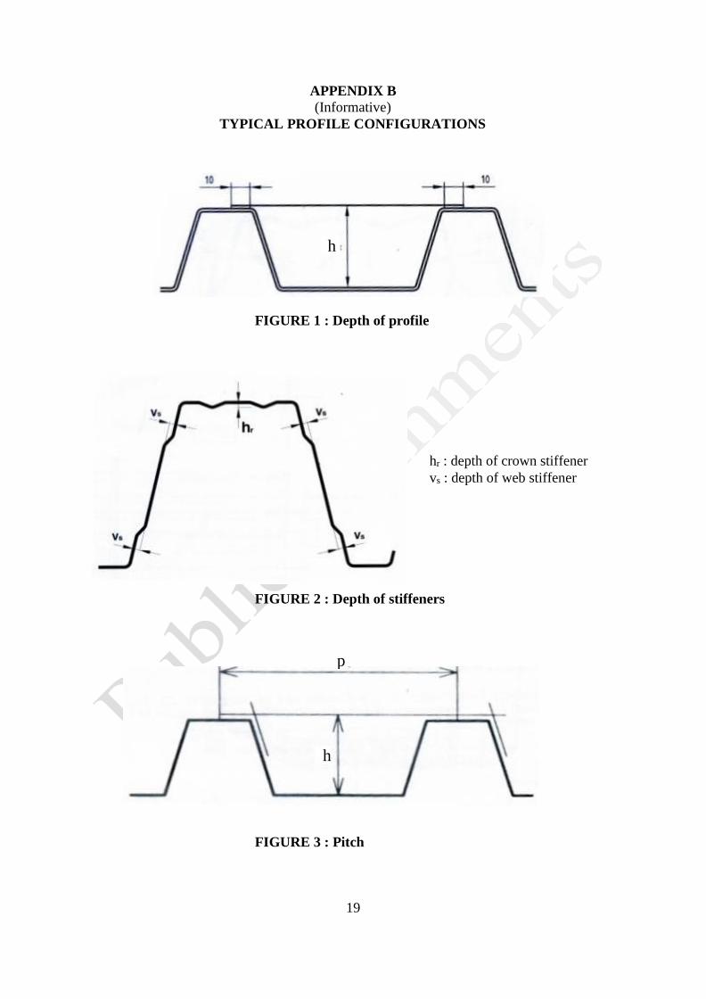
APPENDIX B
(Informative)
TYPICAL PROFILE CONFIGURATIONS
FIGURE 3 : Pitch
h
FIGURE 1 : Depth of profile
hr : depth of crown stiffener
vs : depth of web stiffener
FIGURE 2 : Depth of stiffeners
p
h
20
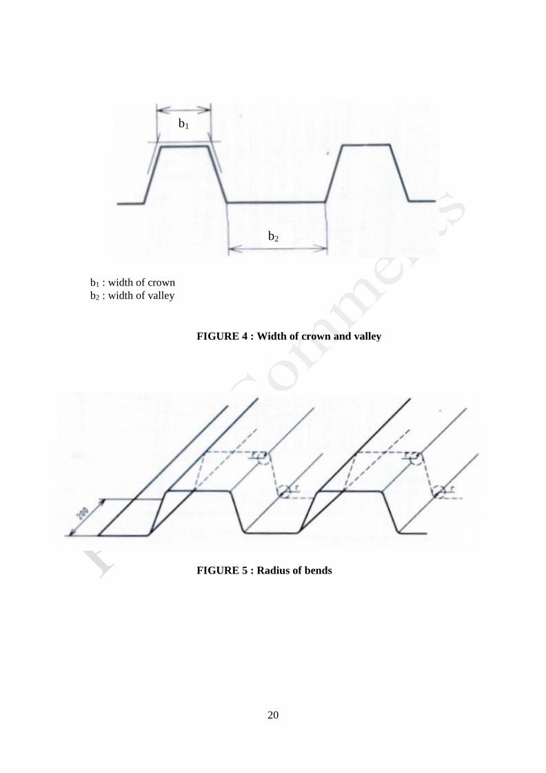
b1 : width of crown
b2 : width of valley
FIGURE 4 : Width of crown and valley
FIGURE 5 : Radius of bends
b2
b1
21
APPENDIX C
(Normative)
MORTAR RESISTANCE TEST
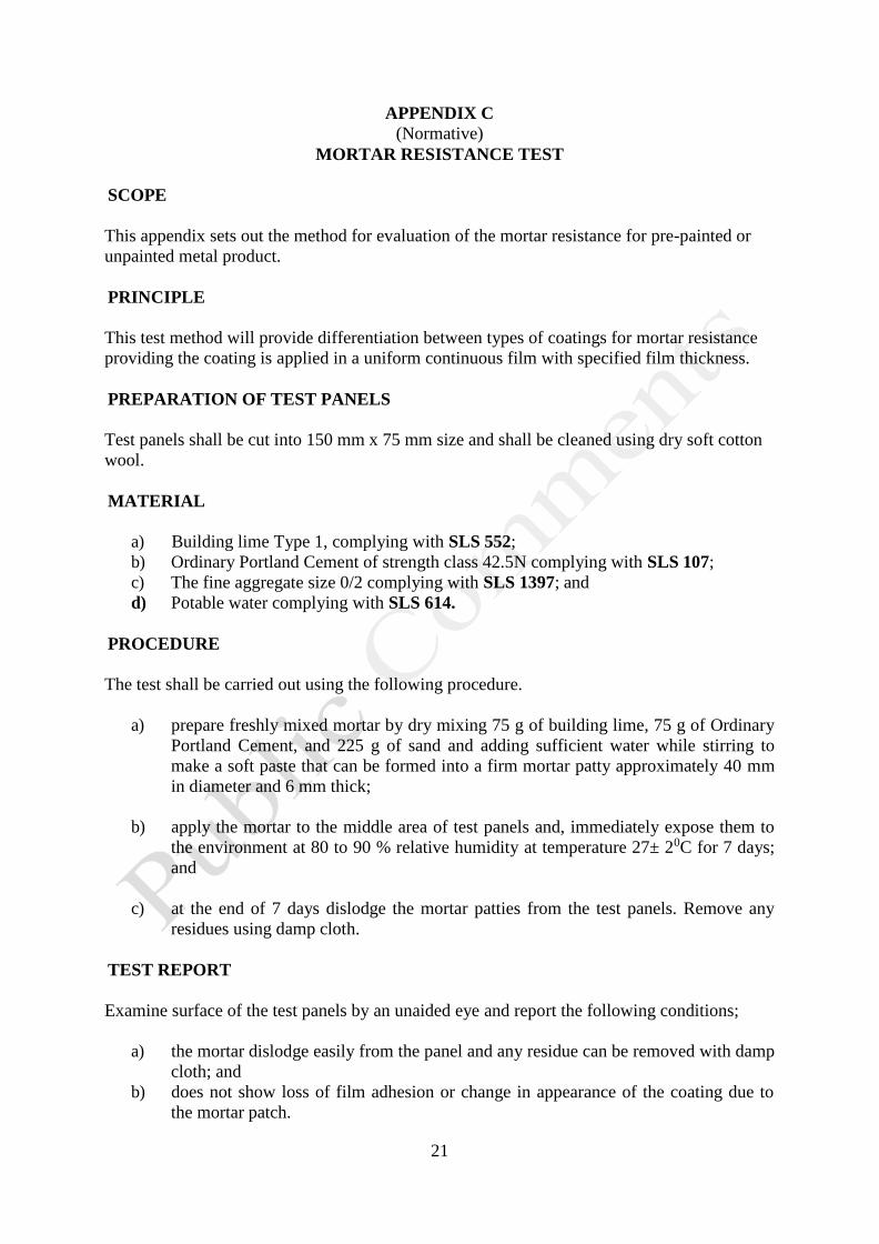
SCOPE
This appendix sets out the method for evaluation of the mortar resistance for pre-painted or
unpainted metal product.
PRINCIPLE
This test method will provide differentiation between types of coatings for mortar resistance
providing the coating is applied in a uniform continuous film with specified film thickness.
PREPARATION OF TEST PANELS
Test panels shall be cut into 150 mm x 75 mm size and shall be cleaned using dry soft cotton
wool.
MATERIAL
a) Building lime Type 1, complying with SLS 552;
b) Ordinary Portland Cement of strength class 42.5N complying with SLS 107;
c) The fine aggregate size 0/2 complying with SLS 1397; and
d) Potable water complying with SLS 614.
PROCEDURE
The test shall be carried out using the following procedure.
a) prepare freshly mixed mortar by dry mixing 75 g of building lime, 75 g of Ordinary
Portland Cement, and 225 g of sand and adding sufficient water while stirring to
make a soft paste that can be formed into a firm mortar patty approximately 40 mm
in diameter and 6 mm thick;
b) apply the mortar to the middle area of test panels and, immediately expose them to
the environment at 80 to 90 % relative humidity at temperature 27± 20C for 7 days;
and
c) at the end of 7 days dislodge the mortar patties from the test panels. Remove any
residues using damp cloth.
TEST REPORT
Examine surface of the test panels by an unaided eye and report the following conditions;
a) the mortar dislodge easily from the panel and any residue can be removed with damp
cloth; and
b) does not show loss of film adhesion or change in appearance of the coating due to
the mortar patch.