Embed Size (px)
Citation preview
Master Thesis
Development and Evaluation of a Small PunchTesting Device
Jan Benjamin Ottosson
Linköping 2010
LIU-IEI-TEK-A–10/00870–SE
Division of Engineering MaterialsDepartment of Management and Engineering (IEI)Linköpings universitet, SE-581 83 Linköping, Sweden

Development and Evaluation of a Small PunchTesting Device
Master’s thesis project conducted atDivision of Engineering Materials
Linköpings universitetby
Jan Benjamin Ottosson
LIU-IEI-TEK-A–10/00870–SE
Supervisor and Examiner: Håkan Brodin
Linköping, 10 June, 2010

Avdelning, InstitutionDivision, Department
Department of Management and EngineeringDivision of Engineering MaterialsLinköpings universitetS-581 83 Linköping, Sweden
DatumDate
2010-006-10
SpråkLanguage
� Svenska/Swedish� Engelska/English
�
�
RapporttypReport category
� Licentiatavhandling� Examensarbete� C-uppsats� D-uppsats� Övrig rapport�
�
URL för elektronisk version
ISBN—
ISRNLIU-IEI-TEK-A–10/00870–SE
Serietitel och serienummerTitle of series, numbering
ISSN—
TitelTitle Development and Evaluation of a Small Punch Testing Device
FörfattareAuthor
Jan Benjamin Ottosson
SammanfattningAbstract
In the turbine industry today, thermal barrier coatings are a commonly used, theseare 0.1-2mm thick. So to be able to do some type of mechanical testing to receivematerial data so one can build an opinion regarding the health of the material. Oneneeds a procedure that can work with small specimens and achieve clear resultsthat can be transformed and compared with known data and known procedures.One of those methods is Small Punch Testing.
This thesis describes one way to develop and test a functioning prototype of aSmall Punch Testing device. The thesis includes; the reason it was developed inthe beginning and how it has been developed throughout the decades, also in whichareas the main research is made. It also shortly describes a working procedure inAnsys to get a Finite Element Method [FEM] model working.
This method showed itself as useful, when just a small sample is at hand. Thetrials in this thesis also show that repetitive test can be done with good resultswhich can be compared with real and FEM analysis data such as σuts.
Inom turbin industrin idag så är keramiska värme barriärer vanligt förekom-mande dessa är normalt 0,1-2mm tjocka. För att kunna utföra mekanisk provningsom grund för att bilda en åsikt om materialets kondition. Så behöver man enmetod som kan åstadkomma tydliga data med små provbitar, Small Punch Test-ing är en av dem.
Den här rapporten beskriver hur man kan gå tillväga för att få en fungerandeprototyp. Den tar upp metodens ursprung och hur den har utvecklats under årtiondena, också mot vad den nuvarande forskningen riktar sig. Den beskriver ävenkort hur man ställer upp en finita element metod [FEM] modell i Ansys.
Metoden visade sig användbar när man bara har en liten provbit att tillgå.Försöken visade att repetitiva tester kan göras med bra resultat som går att jäm-föra med verkliga och FEM analys data.
NyckelordKeywords Small Punch, Ansys, Ultimate Tensile Strenght

AbstractIn the turbine industry today, thermal barrier coatings are a commonly used, theseare 0.1-2mm thick. So to be able to do some type of mechanical testing to receivematerial data so one can build an opinion regarding the health of the material. Oneneeds a procedure that can work with small specimens and achieve clear resultsthat can be transformed and compared with known data and known procedures.One of those methods is Small Punch Testing.
This thesis describes one way to develop and test a functioning prototype of aSmall Punch Testing device. The thesis includes; the reason it was developed inthe beginning and how it has been developed throughout the decades, also in whichareas the main research is made. It also shortly describes a working procedure inAnsys to get a Finite Element Method [FEM] model working.
This method showed itself as useful, when just a small sample is at hand. Thetrials in this thesis also show that repetitive test can be done with good resultswhich can be compared with real and FEM analysis data such as σuts.
Inom turbin industrin idag så är keramiska värme barriärer vanligt förekom-mande dessa är normalt 0,1-2mm tjocka. För att kunna utföra mekanisk provningsom grund för att bilda en åsikt om materialets kondition. Så behöver man enmetod som kan åstadkomma tydliga data med små provbitar, Small Punch Testingär en av dem.
Den här rapporten beskriver hur man kan gå tillväga för att få en fungerandeprototyp. Den tar upp metodens ursprung och hur den har utvecklats under årtiondena, också mot vad den nuvarande forskningen riktar sig. Den beskriver ävenkort hur man ställer upp en finita element metod [FEM] modell i Ansys.
Metoden visade sig användbar när man bara har en liten provbit att tillgå.Försöken visade att repetitiva tester kan göras med bra resultat som går att jäm-föra med verkliga och FEM analys data.
v


Acknowledgements
This master thesis is made as a final project in the programme for a Master of Sci-ence degree in Mechanical Engineering, at the Division of Engineering Materials.I would like to thank my supervisor Håkan Brodin and all the people at the divisionfor their help and I would also like to thank the workshop staff.
Jan Benjamin Ottosson
vii

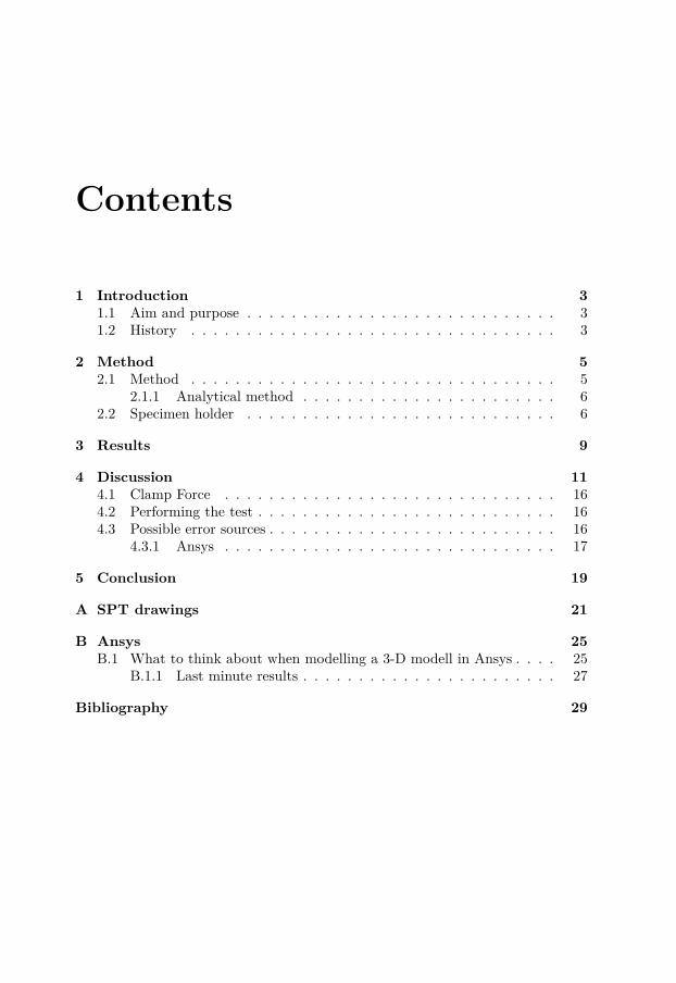
Contents
1 Introduction 31.1 Aim and purpose . . . . . . . . . . . . . . . . . . . . . . . . . . . . 31.2 History . . . . . . . . . . . . . . . . . . . . . . . . . . . . . . . . . 3
2 Method 52.1 Method . . . . . . . . . . . . . . . . . . . . . . . . . . . . . . . . . 5
2.1.1 Analytical method . . . . . . . . . . . . . . . . . . . . . . . 62.2 Specimen holder . . . . . . . . . . . . . . . . . . . . . . . . . . . . 6
3 Results 9
4 Discussion 114.1 Clamp Force . . . . . . . . . . . . . . . . . . . . . . . . . . . . . . 164.2 Performing the test . . . . . . . . . . . . . . . . . . . . . . . . . . . 164.3 Possible error sources . . . . . . . . . . . . . . . . . . . . . . . . . . 16
4.3.1 Ansys . . . . . . . . . . . . . . . . . . . . . . . . . . . . . . 17
5 Conclusion 19
A SPT drawings 21
B Ansys 25B.1 What to think about when modelling a 3-D modell in Ansys . . . . 25
B.1.1 Last minute results . . . . . . . . . . . . . . . . . . . . . . . 27
Bibliography 29

x Contents
Development and Evaluation of a Small PunchTesting Device
Jan Benjamin Ottosson
June 14, 2010

2 Contents
Nomenclature and Equations
d = disc diameter [mm ]
t = disc thickness [mm ]
E = E modulus [GPa ]
σ = tensile strength [MPa ]
ε = strain[% ]
σuts = ultimate tensile strength [MPa ]
dF = displacement at failure [mm ]
Lu = ultimate load [N ]
Cl = die clearance
D = ball diameter [mm ]
A = lower die diameter [mm ]
A = 1.5
D = 1
Equations 1, 2 and has been examined by S.D. Norris and J.D. Parker[1]
σuts = Lut (2.32D − 0.9Cl + 0.56) (1)
σuts = Lut ∗ (0.14D − 0.82Cl + 2.17dF + 0.6) (2)
Cl = A− (D + 2t)
Chapter 1
Introduction
The ability of performing material investigations on small specimens is of greatimportance, especially when it comes to parts that are or has been in service. Smallpunch testing [SPT] has been developed for just that case e.g. to investigate apipe in a nuclear reactor that is still in service, this type of testing can be seen asa non destructive test due to the small specimen size.
1.1 Aim and purposeThe aim of this thesis work is to design and evaluate a SPT device for roomtemperature testing and to see to which theory it corresponds, i.e. uniaxial tensiletest [UTT] or other known methods. It was decided to use a device for roomtemperature testing to start with because it has not previously been done here atLinköping University, it can be seen as a pre-study to a high temperature device.The materials that will be examinined are Al 2524-t3, iron SS1312 and In792,these materials span from ductile to the not that ductile In792.
1.2 HistoryThis type of technique has been around since the early eighties [2][3], foremost tostudy creep in high temperature alloys used in nuclear plants. The first two coun-tries where it started are the USA and Japan. There are two ways to look at SPTtime dependant, for example creep examination at different temperatures thanroom temperature and time independent, examination made at room temperatureto examine e.g. σuts
Nowadays it is mainly used in two different areas, high temperature alloys andultra high molecular weight polyethylene [UHMWPE] in biomaterials [4]. It has itgrounds in that one wants to be able to extract information from small volumes ofmaterial. It can be used for shear force examinations, but in that case one uses aflat punch instead of the ball that is used to examine σuts. In steels one also usesSPT to find out ductile to brittle transition temperature [DBTT] [5]. They look at
3
4 Introduction
the difference between Charpy test [CVN] and SPT the conclusion that they didfind was that the SPT results in a much lower transition temperature, the reasonswhy is closer discussed in the paper. The technique is applicable where there is anecessity to examine a product far too small to be able to produce normal sizedtest specimen. The thermal barrier coating [TBC] of turbine shovels is a goodexample, due to the small thickness of the TBC, 0.1-0.25mm. A common typeof SPT uses transmission electron microscope [TEM] sample sized specimens i.e.3mm in diameter and between 0.1 and 0.5mm in thickness [6]. This is the SPTcommonly known as small punch test, which shall examined closer. One couldbelieve that the disc thickness is not of importance, but in [7] they have lookedcloser at the influence of disc size and one can see that the deflection stays thesame but the thicker the specimen the more force is needed, which one wouldhope to see. In [8] it is mentioned that a aspect ratio, disc diameter/thicknessshould be less than 60 otherwise the specimens showed signs of local deformationand are not acceptable for use, with a aspect ratio over 118 local wrinkling andplastic instability occurs which is useless when a repeatable result is needed. Theyalso mention a thickness tolerance of +-0.0013mm but +-0.0051mm is a nominalacceptable value. Otherwise there is one standardized type with a disc diameterof 8mm and a thickness of 0.5mm used for metals [9][10] and for UHMWPE a discdiameter of 6.4mm and a thickness of 0.5mm[11]. The small sample size makes itcompatible with other non destructive tests. It also makes it possible to actuallytake a sample to examine from a product in use, which is a big advantage. As faras it comes to the design of the test equipment that was seen as the best to go for,has it grounds in two papers [12][13]. But the actual design is made from scratchwith the inner dimensions corresponding to the others.
Chapter 2
Method
2.1 Method
At first a literature study was done, to see what has been done so far, and howit has been made i.e. history. Are there any standards applicable? Then followedthe actual CAD process to bring forth a working prototype, this took longer thanexpected because that it is my first prototype that I have made and I had very littleknowledge in the CAD programme Pro/Engineer 4 before I started. The wholeapparatus will be fitted in a 858 Mini Bionix R© II system with a 10kN loading-cellwhich will be more than sufficient to provide accurate test data. To have a moreexact measurement of the deflection an extensometer will be added under the die tomeasure directly the specimens deflection without any regards to ball compressionetc. In two of the materials that shall be examined, iron SS 1312 and Al 2524-t3,there will also be a UTT done to see how the two different methods correspond toeach other. The TEM sized samples will be produced through different methods,the Al 4010, Al 2524-t3 and SS 1312 will be punched from UTT specimens, In792discs will be produced through cutting a disc and there after follows grinding tothe correct thickness and from those plates the TEM sized specimen will be cutwith electronic discharge machining [EDM]. All the specimens are grinded with500 SiC paper and In792 finished off with 1200 SiC paper. When the discs hadbeen produced the thickness of each was established with a digital dial indicator.The thickness was decided with three significant numbers. Due to the design ofthis device a thickness of maximum 0.25mm is a must. Larger thickness will leadto something equivalent to deep drawing of aluminium cans, highly undesirable.
Performing the test
The actual test was performed with a speed of 0.15mm/min which results in in-formation about force and deflection during the test. The clamping force for Al2524-t3 ended up at 750-850N if more was applied the plate was plastically de-formed. For SS 1312 and In792 a higher clamp force was applied 1150-1350N.
5
6 Method
2.1.1 Analytical methodThe analytical methods used for comparison is the computer software Ansys Work-bench v.12 and equations 1 and 2 derived by S.D. Norris and J.D. Parker for moreinformaiton about the equations see [1].
Ansys
A model was created in Ansys Workbench Static Structural which is a modernFEM software with graphical interface, to have more numerical data to comparewith. When it came to achieve a working model in Ansys, there were a lot ofproblems getting it right due to all the constraints working in the model. Allthese questions had to be answered before implementing them: friction betweendifferent types of materials acting together? what type of load should be applied?2-D or 3-D? Which type of mesh gives most relying result in the model? The lastquestion could actually be answered after the model was working by trial and error.Some types of mesh gave some really disturbing results for example, deformationthat cannot occur. Due to the complexity of the model friction coefficients hadto be decided for each contact surface Cambridge Engineering Selector[14] wasused in combination with [15] to establish them. Two types of elements tetragonaland quad was tried, also different mesh concentrations, from 4500 up to 6500.The difference in deflection is 0.6% which for my application is negligible and inthe stresses measured according to von-Mises the difference was 2% which alsois negligible. So the simulations are run with the lower mesh with quad mesh,to lower the time needed to do the calculations. The model used in this case isin 3-D to make it simpler to understand. The mesh used is in Ansys referred toas SOLD186, quad with 20 nodes. In Appendix B deeper information about theprocedures in Ansys can be found.
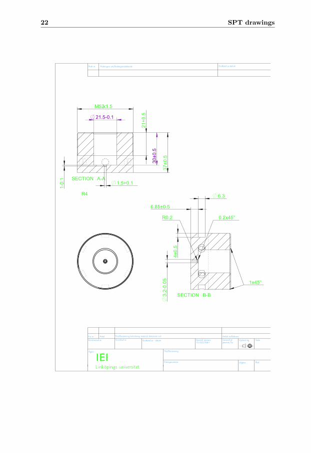
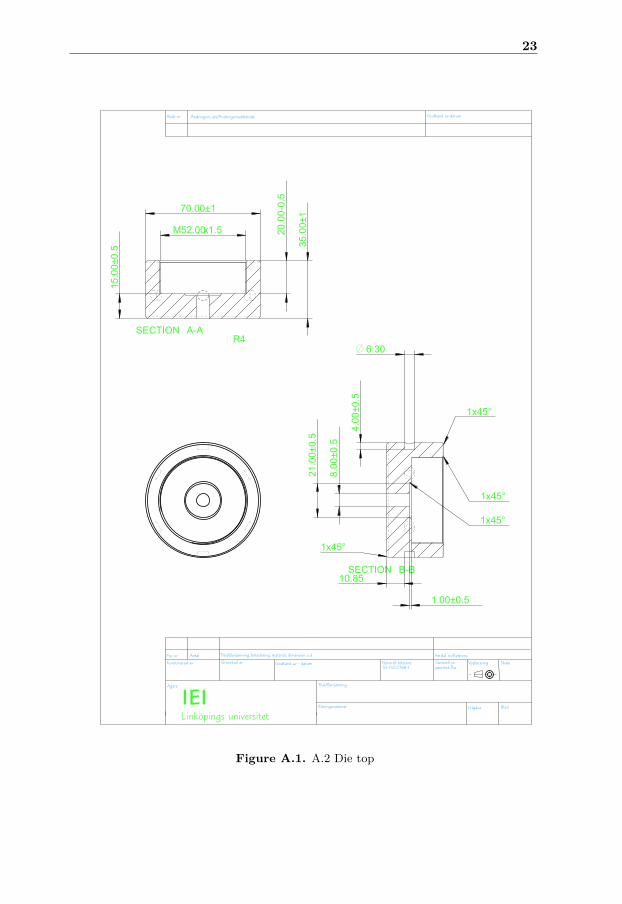
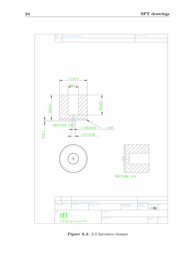
2.2 Specimen holderThe first thing done was a literature study to find information, if there was astandard, if not which dimensions where most commonly used for the TEM sizedspecimens. Drawings were not found but applicable dimensions, but then therewas the shape, outer size and function to determine. At this stage consultaionswas made, with different persons working at the university and my supervisor anddiscussed different prototypes and concluded that according to this principle thatthe current prototype is built by is the most probable to succeed. Another obstacleencountered was how narrow should the different dimensions be, especially thespecimen clamper with its small diameter hole and the area under the sample witha radius of 0.2mm to prevent shearing to occur. The material for the device wasalso to be determined and after many different propositions Uddeholm Vanadis R© 4Extra was chosen for the critical parts(A.1., A.3.) due to its good properties, highwear resistance and high ductility which leads to high resistance against adhesivewearing and chipping. Through hardening, a hardness up to 66 HRC is achievable,which is in our application desirable. For the non critical parts steel will be used.
2.2 Specimen holder 7
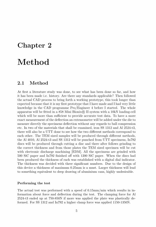
Besides that the force will be measured as well as the deflection. To be able todo this a holder for the SPT device had to be made. Here some problem due tothe physical limitations of the 858 Mini Bionix R© II was encountered. To holdthe specimens under clamp force. It was designed so that disc springs can beused to apply a different clamp force if it becomes necessary to change betweendifferent materials, which is most likely to be done between aluminium and In792.To be able to screw it together some type of grip had to be implemented, millingmachines have a similar shape as the prototype has. So specifications for howC-Spanners work was included into the design. As punch Cr-steel balls with ahardness of 60/66HRC will be used and as ball pusher a rod of 99.7% Al2O3 willbe used all this to minimize malfunction and interference during testing.
Figure 2.1. Device setup
Figure 2.1 shows the device setup in the machine, showing the black load celland with its puncher.

8 Method
Chapter 3
Results
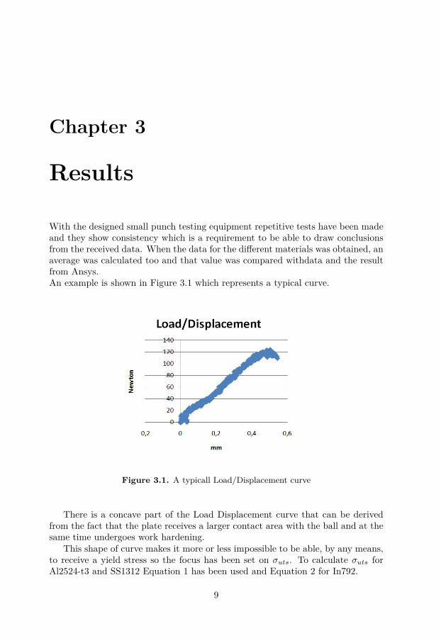
With the designed small punch testing equipment repetitive tests have been madeand they show consistency which is a requirement to be able to draw conclusionsfrom the received data. When the data for the different materials was obtained, anaverage was calculated too and that value was compared withdata and the resultfrom Ansys.An example is shown in Figure 3.1 which represents a typical curve.
Figure 3.1. A typicall Load/Displacement curve
There is a concave part of the Load Displacement curve that can be derivedfrom the fact that the plate receives a larger contact area with the ball and at thesame time undergoes work hardening.
This shape of curve makes it more or less impossible to be able, by any means,to receive a yield stress so the focus has been set on σuts. To calculate σuts forAl2524-t3 and SS1312 Equation 1 has been used and Equation 2 for In792.
9
10 Results
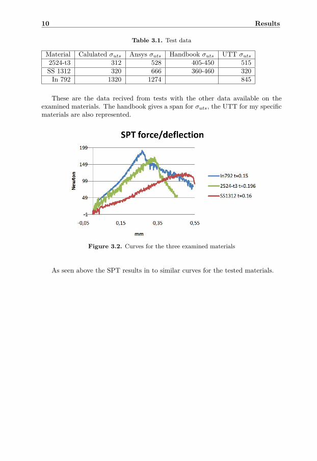
Table 3.1. Test data
Material Calulated σuts Ansys σuts Handbook σuts UTT σuts2524-t3 312 528 405-450 515SS 1312 320 666 360-460 320In 792 1320 1274 845
These are the data recived from tests with the other data available on theexamined materials. The handbook gives a span for σuts, the UTT for my specificmaterials are also represented.
Figure 3.2. Curves for the three examined materials
As seen above the SPT results in to similar curves for the tested materials.
Chapter 4
Discussion
The calculated σuts for In792 is really close to the value from Ansys.The Al 2524-t3 shows good correlation between the Ansys result and the UTT,but a significant difference to the calculatded value.For SS 1312 the calculated σuts and the UTT it is a perfect match but betweenAnsys and UTT the value received from Ansys is more than twice as high as forthe other values.As stated in [7] equation 1 and 2 are a good point of origin to find a more specificequation for the material that one is conducting research on at the moment, theneed to do that can easily be deduced from the analyzed data. If there hadbeen more consistency between the materials it would have been better. Of threedifferent pairing options all three were hit but this probably lies in the fact thatthree very different types of materials was chosen, this to induce variating resultswhich was received. The method is not perfect but when properly used a reallygood option.
11
12 Discussion
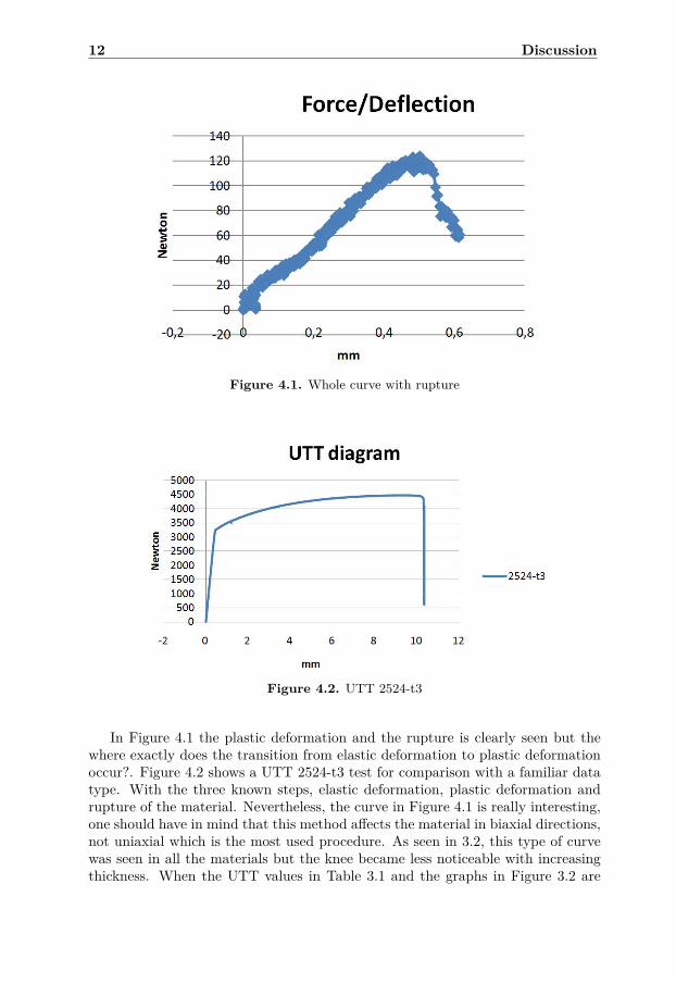
Figure 4.1. Whole curve with rupture
Figure 4.2. UTT 2524-t3
In Figure 4.1 the plastic deformation and the rupture is clearly seen but thewhere exactly does the transition from elastic deformation to plastic deformationoccur?. Figure 4.2 shows a UTT 2524-t3 test for comparison with a familiar datatype. With the three known steps, elastic deformation, plastic deformation andrupture of the material. Nevertheless, the curve in Figure 4.1 is really interesting,one should have in mind that this method affects the material in biaxial directions,not uniaxial which is the most used procedure. As seen in 3.2, this type of curvewas seen in all the materials but the knee became less noticeable with increasingthickness. When the UTT values in Table 3.1 and the graphs in Figure 3.2 are
13
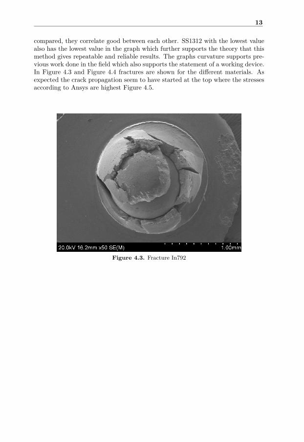
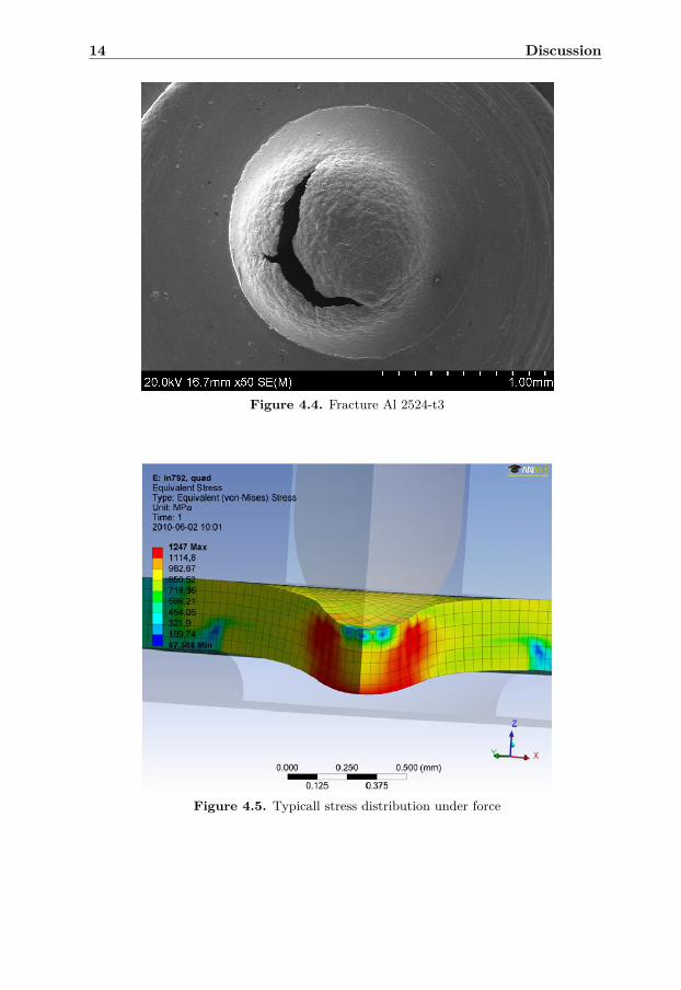
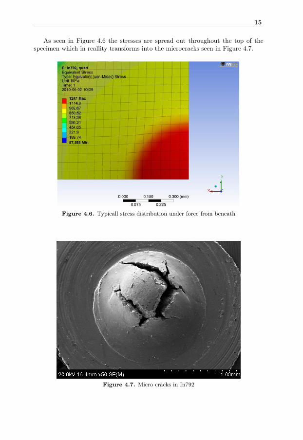
compared, they correlate good between each other. SS1312 with the lowest valuealso has the lowest value in the graph which further supports the theory that thismethod gives repeatable and reliable results. The graphs curvature supports pre-vious work done in the field which also supports the statement of a working device.In Figure 4.3 and Figure 4.4 fractures are shown for the different materials. Asexpected the crack propagation seem to have started at the top where the stressesaccording to Ansys are highest Figure 4.5.
Figure 4.3. Fracture In792
14 Discussion
Figure 4.4. Fracture Al 2524-t3
Figure 4.5. Typicall stress distribution under force
15
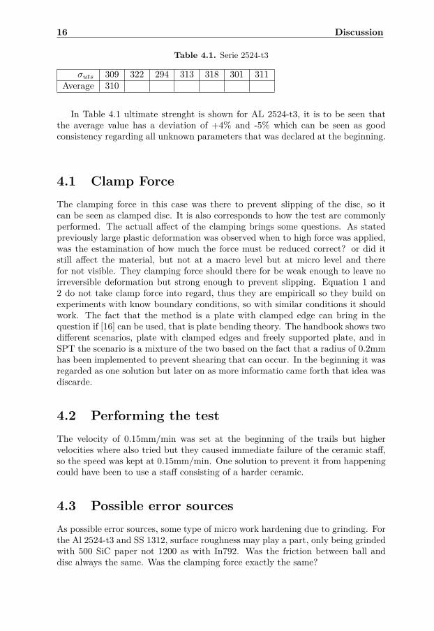
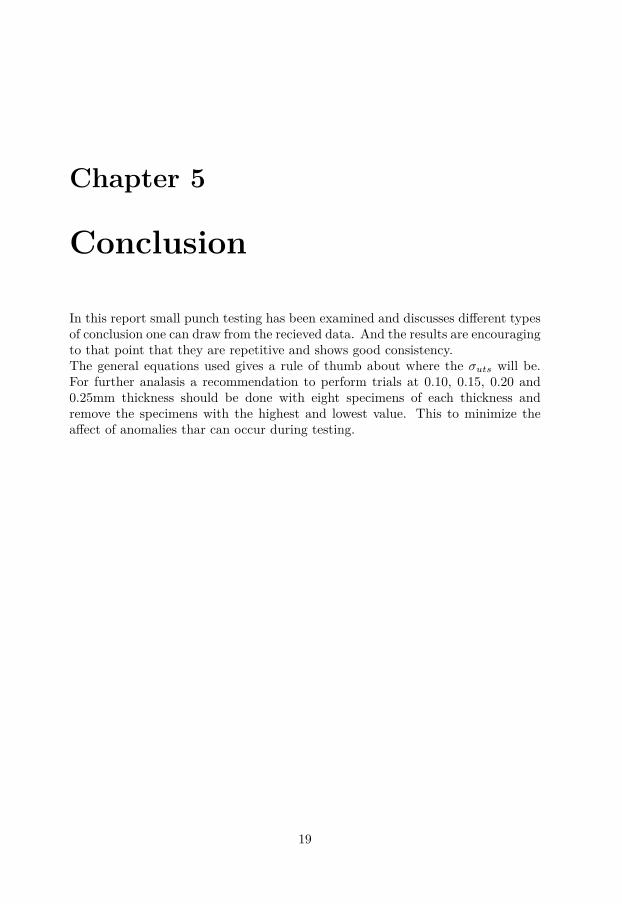
As seen in Figure 4.6 the stresses are spread out throughout the top of thespecimen which in reallity transforms into the microcracks seen in Figure 4.7.
Figure 4.6. Typicall stress distribution under force from beneath
Figure 4.7. Micro cracks in In792
16 Discussion
Table 4.1. Serie 2524-t3
σuts 309 322 294 313 318 301 311Average 310
In Table 4.1 ultimate strenght is shown for AL 2524-t3, it is to be seen thatthe average value has a deviation of +4% and -5% which can be seen as goodconsistency regarding all unknown parameters that was declared at the beginning.
4.1 Clamp ForceThe clamping force in this case was there to prevent slipping of the disc, so itcan be seen as clamped disc. It is also corresponds to how the test are commonlyperformed. The actuall affect of the clamping brings some questions. As statedpreviously large plastic deformation was observed when to high force was applied,was the estamination of how much the force must be reduced correct? or did itstill affect the material, but not at a macro level but at micro level and therefor not visible. They clamping force should there for be weak enough to leave noirreversible deformation but strong enough to prevent slipping. Equation 1 and2 do not take clamp force into regard, thus they are empiricall so they build onexperiments with know boundary conditions, so with similar conditions it shouldwork. The fact that the method is a plate with clamped edge can bring in thequestion if [16] can be used, that is plate bending theory. The handbook shows twodifferent scenarios, plate with clamped edges and freely supported plate, and inSPT the scenario is a mixture of the two based on the fact that a radius of 0.2mmhas been implemented to prevent shearing that can occur. In the beginning it wasregarded as one solution but later on as more informatio came forth that idea wasdiscarde.
4.2 Performing the testThe velocity of 0.15mm/min was set at the beginning of the trails but highervelocities where also tried but they caused immediate failure of the ceramic staff,so the speed was kept at 0.15mm/min. One solution to prevent it from happeningcould have been to use a staff consisting of a harder ceramic.
4.3 Possible error sourcesAs possible error sources, some type of micro work hardening due to grinding. Forthe Al 2524-t3 and SS 1312, surface roughness may play a part, only being grindedwith 500 SiC paper not 1200 as with In792. Was the friction between ball anddisc always the same. Was the clamping force exactly the same?

4.3 Possible error sources 17
4.3.1 AnsysIn Ansys some obvious error sources are the defined parameters as friction coef-ficients, clamp force, the fact that it is not a transient analasis(it does not useconstant speed), mesh type and size. Most of these are taken into considerationbut there is always room for errors.

18 Discussion
Chapter 5
Conclusion
In this report small punch testing has been examined and discusses different typesof conclusion one can draw from the recieved data. And the results are encouragingto that point that they are repetitive and shows good consistency.The general equations used gives a rule of thumb about where the σuts will be.For further analasis a recommendation to perform trials at 0.10, 0.15, 0.20 and0.25mm thickness should be done with eight specimens of each thickness andremove the specimens with the highest and lowest value. This to minimize theaffect of anomalies thar can occur during testing.
19

20 Conclusion

Appendix A
SPT drawings
21
22 SPT drawings
Konstruerad av
Artikel nr/Referens
Ägare
Utgåva Blad
Titel/Benämning
SkalaVyplaceringjämnhet, RaGenerell yt-
Ritningsnummer
Pos nr AntalGranskad av Generell toleransGodkänd av - datum
SS-ISO2768-1
Titel/Benämning, beteckning, material, dimension o.d.
IEILinköpings universitet
Godkänd av-datumÄndr nr Ändringens art/Ändringsmeddelande
M52x1.5
21.5-0.1
37±0
.5
30±0
.5
1.5+0.1
3.2-
0.05
21+0
.5
1-0.
1
4±0.
5
6.3
6.85±0.5
A-ASECTION
R4
B-BSECTION
0.2x45°R0.2
1x45°
23
Konstruerad av
Artikel nr/Referens
Ägare
Utgåva Blad
Titel/Benämning
SkalaVyplaceringjämnhet, RaGenerell yt-
Ritningsnummer
Pos nr AntalGranskad av Generell toleransGodkänd av - datum
SS-ISO2768-1
Titel/Benämning, beteckning, material, dimension o.d.
IEILinköpings universitet
Godkänd av-datumÄndr nr Ändringens art/Ändringsmeddelande
70.00±1
M52.00x1.5
35.0
0±1
21.0
0±0.
5
8.00
±0.5
20.0
0-0.
5
1.00±0.5
4.00
±0.5
10.85
6.30
15.0
0±0.
5
B-BSECTION
1x45°
1x45°
1x45°
1x45°
A-ASECTION R4
Figure A.1. A.2 Die top
24 SPT drawings
Konstruerad av
Artikel nr/Referens
Ägare
Utgåva Blad
Titel/Benämning
SkalaVyplaceringjämnhet, RaGenerell yt-
Ritningsnummer
Pos nr AntalGranskad av Generell toleransGodkänd av - datum
SS-ISO2768-1
Titel/Benämning, beteckning, material, dimension o.d.
IEILinköpings universitet
Godkänd av-datumÄndr nr Ändringens art/Ändringsmeddelande
21+0.1
8±0.2
3.1+0.05
1.05±0.01
1+0.
1
15±0
.5
19±0
.5
A-ASECTION
C-CSECTION 1x45°
Figure A.2. A.3 Specimen clamper
Appendix B
Ansys
B.1 What to think about when modelling a 3-Dmodell in Ansys
In this thesis Ansys Workbench v. 12 Static Structural was used. The problemsdo not only lie in the choosing of mesh, in my case that was the easy part. Thereal problem was to find what specific commands that has to be turned on whenworking with a 3-D non-linear model with large deformation. How to define theproper connections and constraints. Here follows a short list with the most criticalsettings in my modell.
In Commands file;
CNCHECK, AUTO
In the outline tree
Behaviour: Asymmetric
Formulation: Augmented Lagrange
Normal Stiffness: Manual
Normal Stiffness Factor: between 0.01-0.04
Large Deflection: ON
Weak Springs: Program Controlled
In Solutions be careful for what you want, think twice when defining in Scopewhich bodies/surfaces one want to receive data from, most probably not the wholesystem.
25
26 Ansys
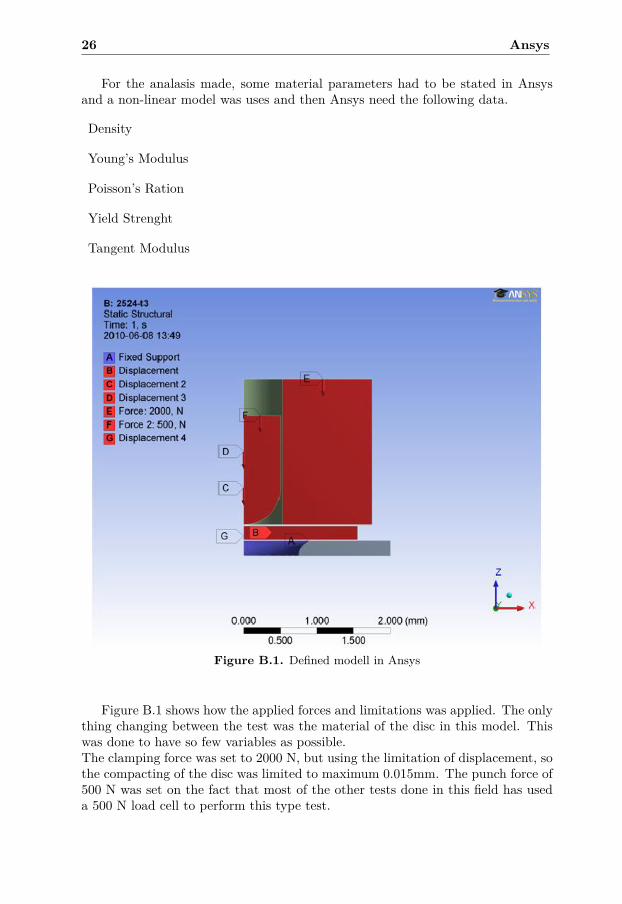
For the analasis made, some material parameters had to be stated in Ansysand a non-linear model was uses and then Ansys need the following data.
Density
Young’s Modulus
Poisson’s Ration
Yield Strenght
Tangent Modulus
Figure B.1. Defined modell in Ansys
Figure B.1 shows how the applied forces and limitations was applied. The onlything changing between the test was the material of the disc in this model. Thiswas done to have so few variables as possible.The clamping force was set to 2000 N, but using the limitation of displacement, sothe compacting of the disc was limited to maximum 0.015mm. The punch force of500 N was set on the fact that most of the other tests done in this field has useda 500 N load cell to perform this type test.
B.1 What to think about when modelling a 3-D modell in Ansys 27
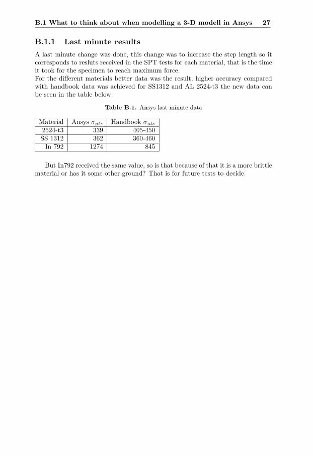
B.1.1 Last minute resultsA last minute change was done, this change was to increase the step length so itcorresponds to resluts received in the SPT tests for each material, that is the timeit took for the specimen to reach maximum force.For the different materials better data was the result, higher accuracy comparedwith handbook data was achieved for SS1312 and AL 2524-t3 the new data canbe seen in the table below.
Table B.1. Ansys last minute data
Material Ansys σuts Handbook σuts2524-t3 339 405-450SS 1312 362 360-460In 792 1274 845
But In792 received the same value, so is that because of that it is a more brittlematerial or has it some other ground? That is for future tests to decide.

28 Ansys
Bibliography
[1] S. D. Norris and J. D. Parker. Deformation processes during disc bend loading.Materials Science and Technology, 12:163–170(8), February 1996.
[2] Jai-Man Baik, J. Kameda, and O. Buck. Small punch test evaluation of inter-granular embrittlement of an alloy steel. Scripta Metallurgica, 17(12):1443–1447, 12 1983.
[3] G. E. Lucas. The development of small specimen mechanical test techniques.Journal of Nuclear Materials, 117:327–339, 7 1983.
[4] S. M. Kurtz, C. W. Jewett, J. S. Bergström, J. R. Foulds, and A. A. Edidin.Miniature specimen shear punch test for uhmwpe used in total joint replace-ments. Biomaterials, 23(9):1907–1919, 5 2002.
[5] M. A. Contreras, C. Rodríguez, F. J. Belzunce, and C. Betegón. Use of thesmall punch test to determine the ductile-to-brittle transition temperature ofstructural steels. Fatigue and Fracture of Engineering Materials and Struc-tures, 31(9):727–737, 2008. Cited By (since 1996): 1.
[6] T. Misawa, T. Adachi, M. Saito, and Y. Hamaguchi. Small punch tests forevaluating ductile-brittle transition behavior of irradiated ferritic steels. Jour-nal of Nuclear Materials, 150(2):194–202, 10 1987.
[7] Zhao-Xi Wang, Hui-Ji Shi, Jian Lu, Pan Shi, and Xian-Feng Ma. Small punchtesting for assessing the fracture properties of the reactor vessel steel withdifferent thicknesses. Nuclear Engineering and Design, 238(12):3186–3193, 122008.
[8] T. H. Hyde, W. Sun, and J. A. Williams. Requirements for and use of minia-ture test specimens to provide mechanical and creep properties of materials:a review. International Materials Reviews, 52:213–255(43), July 2007.
[9] D. T. Blagoeva and R. C. Hurst. Application of the cen (european com-mittee for standardization) small punch creep testing code of practice to arepresentative repair welded p91 pipe. Materials Science and Engineering A,510-511(C):219–223, 2009.
[10] Cwa 15627:2007 small punch test method for metallic materials.
29
30 Bibliography
[11] Standard test method for small punch testing of ultra-high molecular weightpolyethylene used in surgical implants.
[12] E. N. Campitelli, P. Spätig, R. Bonadé, W. Hoffelner, and M. Victoria. Assess-ment of the constitutive properties from small ball punch test: Experimentand modeling. Journal of Nuclear Materials, 335(3):366–378, 2004. Cited By(since 1996): 19.
[13] Mats Eskner and Rolf Sandström. Measurement of the ductile-to-brittle tran-sition temperature in a nickel aluminide coating by a miniaturised disc bend-ing test technique. Surface and Coatings Technology, 165(1):71–80, 2/3 2003.
[14] Granta Design. Cambridge engineering selector, 2009.
[15] Tribology.
[16] Ansel C. Ugural. Stresses in plates and shells, pages 120–121, Case 5,8. WCBMcGraw-Hill, Internatilnal Editions, second edition edition, 1999.