Embed Size (px)
Citation preview
7
Aluform
• Aluminium diecast enclosure for MCR and automation technology• Prepared for acceptance for front membranes and keypads• Rectangular dome sequence in lid and base
Included in deliveryAluminium diecast enclosure consisting of lid, seal incl. captive +/- stainless steel screws, base with 4 earthing screws
Technical Data
Material:
DIN EN 1706 EN AC-AlSi 12 (Fe)
Painting:
powder coating
Colour:
RAL 7038, agate grey
special colour on request
Ingress protection:
IP 66 to EN 60529
higher protection on request
Impact resistance:
7 Joule to EN 60079-0
Temperature range:
PU (polyurethane) seal (std.): -40°C to +90°C
CR (chloroprene) seal: -40°C to +100°C
VMQ (silicone) seal (optional): -60°C to +130°C
8
Aluform
1) Laminated paper 2) Stainless steel 3) Diecast aluminium 4) Please quote the installation side A-D when ordering
Accessories
Product rangeOrder No. B x L x H (mm) Mounting plate DIN rail TS 15 DIN rail TS 35 External mounting brackets (pair)
04.08 08 08 80 x 80 x 81 10.01 10 60 10.06 10 03 04.00 00 80
04.08 12 05 80 x 120 x 51 10.01 10 61 04.00 00 80
04.08 12 08 80 x 120 x 81 10.01 10 61 10.06 10 50 04.00 00 80
04.10 10 06 100 x 100 x 61 10.01 10 31 10.06 10 07 10.06 14 71 04.00 01 00
04.10 16 06 100 x 160 x 61 10.01 10 32 10.06 10 08 10.06 14 72 04.00 01 00
04.10 20 06 100 x 200 x 61 10.01 10 33 10.06 10 09 10.06 14 73 04.00 01 00
04.12 12 08 120 x 120 x 81 10.01 10 62 10.06 10 50 10.06 14 83 04.00 01 20
04.12 16 08 120 x 160 x 81 10.01 10 63 10.06 10 08 10.06 14 72 04.00 01 20
04.14 14 07 140 x 140 x 71 10.01 10 34 10.06 10 44 10.06 14 74 04.00 01 40
04.14 18 07 140 x 180 x 71 10.01 10 35 10.06 10 05 10.06 14 75 04.00 01 40
04.14 22 07 140 x 220 x 72 10.01 10 36 10.06 10 46 10.06 14 76 04.00 01 40
04.15 18 08 150 x 180 x 81 10.01 10 70 on request on request
04.16 16 08 160 x 160 x 81 10.01 10 64 10.06 10 08 10.06 14 72 04.00 01 60
04.16 24 08 160 x 240 x 81 10.01 10 65 10.06 10 51 10.06 14 84 04.00 01 60
04.20 20 07 200 x 200 x 72 10.01 10 37 10.06 10 09 10.06 14 73 04.00 02 00
04.20 28 07 200 x 280 x 72 10.01 10 59 10.06 10 48 10.06 14 81 04.00 02 00
04.28 28 11 280 x 280 x 111 10.01 10 71 10.06 10 48 10.06 14 81
Type DIN rails for terminals
TS 15 TS 35
Mountingplate
1)
External mounting bracketspair
External alu-minium hingespair3), 4)
EMC screening
SWB/SBG/ SBGLCorrosion protection
Allen lid screws2)
Silicone lid seal up to +130°C
Sealable lid screws in steel
Lid safety strip
04.08 08 08 • • • • • • • • • •
04.08 12 05 • • • • • • • • •
04.08 12 08 • • • • • • • • • •
04.10 10 06 • • • • • • • • • • •
04.10 16 06 • • • • • • • • • • •
04.10 20 06 • • • • • • • • • • •
04.12 12 08 • • • • • • • • • • •
04.12 16 08 • • • • • • • • • • •
04.14 14 07 • • • • • • • • • • •
04.14 18 07 • • • • • • • • • • •
04.14 22 07 • • • • • • • • • • •
04.15 18 08 • • • • • • • • • •
04.16 16 08 • • • • • • • • • • •
04.16 24 08 • • • • • • • • • • •
04.20 20 07 • • • • • • • • • • •
04.20 28 07 • • • • • • • • • • •
04.28 28 11 • • • • • • • • • •
9
Aluform
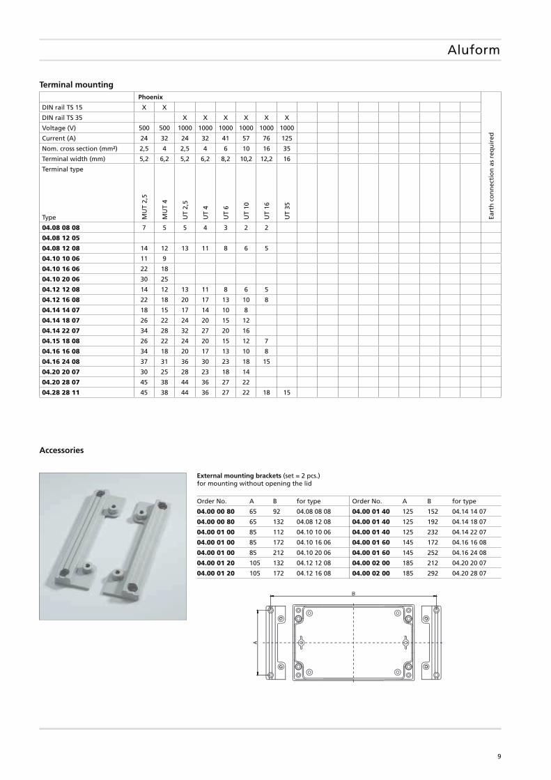
Terminal mounting Phoenix
Eart
h c
on
nec
tio
n a
s re
qu
ired
DIN rail TS 15 X X
DIN rail TS 35 X X X X X X
Voltage (V) 500 500 1000 1000 1000 1000 1000 1000
Current (A) 24 32 24 32 41 57 76 125
Nom. cross section (mm²) 2,5 4 2,5 4 6 10 16 35
Terminal width (mm) 5,2 6,2 5,2 6,2 8,2 10,2 12,2 16
Terminal type
MU
T 2,
5
MU
T 4
UT
2,5
UT
4
UT
6
UT
10
UT
16
UT
35
Type
04.08 08 08 7 5 5 4 3 2 2
04.08 12 05
04.08 12 08 14 12 13 11 8 6 5
04.10 10 06 11 9
04.10 16 06 22 18
04.10 20 06 30 25
04.12 12 08 14 12 13 11 8 6 5
04.12 16 08 22 18 20 17 13 10 8
04.14 14 07 18 15 17 14 10 8
04.14 18 07 26 22 24 20 15 12
04.14 22 07 34 28 32 27 20 16
04.15 18 08 26 22 24 20 15 12 7
04.16 16 08 34 18 20 17 13 10 8
04.16 24 08 37 31 36 30 23 18 15
04.20 20 07 30 25 28 23 18 14
04.20 28 07 45 38 44 36 27 22
04.28 28 11 45 38 44 36 27 22 18 15
Accessories
External mounting brackets (set = 2 pcs.)for mounting without opening the lid
Order No. A B for type Order No. A B for type
04.00 00 80 65 92 04.08 08 08 04.00 01 40 125 152 04.14 14 07
04.00 00 80 65 132 04.08 12 08 04.00 01 40 125 192 04.14 18 07
04.00 01 00 85 112 04.10 10 06 04.00 01 40 125 232 04.14 22 07
04.00 01 00 85 172 04.10 16 06 04.00 01 60 145 172 04.16 16 08
04.00 01 00 85 212 04.10 20 06 04.00 01 60 145 252 04.16 24 08
04.00 01 20 105 132 04.12 12 08 04.00 02 00 185 212 04.20 20 07
04.00 01 20 105 172 04.12 16 08 04.00 02 00 185 292 04.20 28 07
10
Aluform
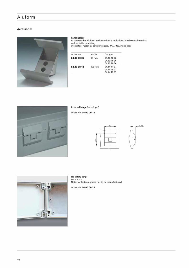
Accessories
Panel holderto convert the Aluform enclosure into a multi-functional control terminalwall or table mountingsheet steel material; powder coated, RAL 7030, stone grey
External hinge (set = 2 pcs)
Order No. 04.00 00 10
Lid safety strip set = 2 pcs. Note: for fastening base has to be manufactured
Order No. 04.00 00 20
Order No. width for type
04.30 00 09 98 mm 04.10 10 06 04.10 16 06 04.10 20 06
04.30 00 14 138 mm 04.14 14 07 04.14 18 07 04.14 22 07
11
71
109 / 107*
87,5 / 85,1*
25,5
/ 2
3,5*
69 /
66,
580
/ 7
8*
120 / 118*
53
Deckel
* = Maß durch Formkonizität nach unten verringert Freimaß - Toleranz nach GTA13/5 DIN 1688
f. Schneid-schraube M4
94
Ansicht F
91,5 / 89,5*
120 / 118*
75,5
97105
435765
18 /
17*
29,5
/ 2
7,5*
73 /
71*
113 / 111*
80 /
78*
R2
R2Unterteil
B
DC
A
4,5
1
3151 (Gesamthöhe)
8,5
/ 7,
5*
4,3
11,5
20
4,5
3
9
11
42,5 (max. Einbauhöhe)
Oben
Zyl.-schraubeM4x20/7 ähnl. DIN84
E F
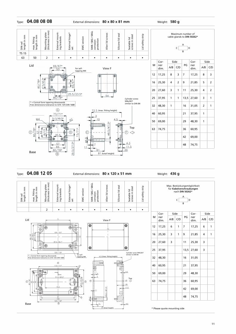
Type: 04.08 08 08 External dimensions: 80 x 80 x 81 mm Weight: 580 g
Base
Lid
* = Conical form tapering downwardsFree dimensions-tolerance to GTA 13/5 DIN 1688
for self-tapping M4
View F
Cylinder screwM4x20/7similar to DIN 84
(max. fitting height)
(total height)
Top
Maximum number of cable glands to DIN 50262*
C DA
B
MCor-ner dim.
SidePG
Cor-ner dim.
Side
A/B C/D A/B C/D
12 17,25 8 3 7 17,25 8 3
16 25,30 4 2 9 21,85 5 2
20 27,60 3 1 11 25,30 4 2
25 37,95 1 1 13,5 27,60 3 1
32 48,30 1 16 31,05 2 1
40 60,95 21 37,95 1
50 69,00 29 48,30 1
63 74,75 36 60,95
42 69,00
48 74,75
DIN
rai
lle
ng
th in
mm
max
. fitt
ing
le
ng
th in
mm
Mo
un
tin
g p
late
(t
hic
knes
s in
mm
)
Exte
rnal
mo
un
t-in
g b
rack
ets
Exte
rnal
hin
ge*
se
t
EMC
ver
sio
n
SWB
/ SB
G /
SBG
Lco
rro
sio
n
pro
tect
ion
Alle
n li
d s
crew
s
Silic
on
e lid
sea
l
Seal
able
lid
sc
rew
s in
ste
el
Lid
saf
ety
stri
p
TS 15
63 50 2 • • • • • • • •
Max. Bestückungsmöglichkeit für Kabelverschraubungen
nach DIN 50262*
Type: 04.08 12 05 External dimensions: 80 x 120 x 51 mm Weight: 436 g
C DA
B
MCor-ner dim.
SidePG
Cor-ner dim.
Side
A/B C/D A/B C/D
12 17,25 6 1 7 17,25 6 1
16 25,30 3 1 9 21,85 4 1
20 27,60 3 11 25,30 3
25 37,95 13,5 27,60 3
32 48,30 16 31,05
40 60,95 21 37,95
50 69,00 29 48,30
63 74,75 36 60,95
42 69,00
48 74,75
DIN
rai
lle
ng
th in
mm
max
. fitt
ing
le
ng
th in
mm
Mo
un
tin
g p
late
(t
hic
knes
s in
mm
)
Exte
rnal
mo
un
t-in
g b
rack
ets
Exte
rnal
hin
ge*
se
t
EMC
ver
sio
n
SWB
/ SB
G /
SBG
Lco
rro
sio
n
pro
tect
ion
Alle
n li
d s
crew
s
Silic
on
e lid
sea
l
Seal
able
lid
sc
rew
s in
ste
el
Lid
saf
ety
stri
p
2 • • • • • • • •
Base
Lid
* = Conical form tapering downwardsFree dimensions-tolerance to GTA 13/5 DIN 1688
for self-tapping M4
View F
(max. fitting height)
(total height)
Top
Cylinder screw M4x20/7similar to DIN 84
* Please quote mounting side
12
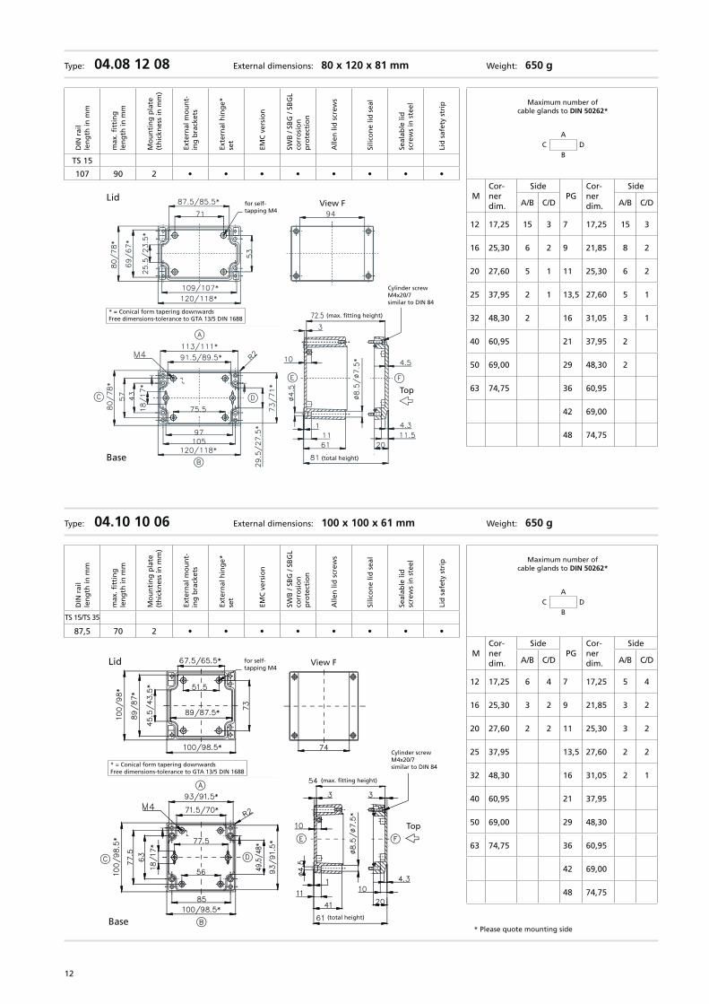
Type: 04.10 10 06 External dimensions: 100 x 100 x 61 mm Weight: 650 g
Base
Lid
* = Conical form tapering downwardsFree dimensions-tolerance to GTA 13/5 DIN 1688
for self-tapping M4
View F
Cylinder screwM4x20/7similar to DIN 84
(max. fitting height)
(total height)
Top
Type: 04.08 12 08 External dimensions: 80 x 120 x 81 mm Weight: 650 g
Base
Lid
* = Conical form tapering downwardsFree dimensions-tolerance to GTA 13/5 DIN 1688
for self-tapping M4
View F
Cylinder screwM4x20/7similar to DIN 84
(max. fitting height)
(total height)
Top
Maximum number of cable glands to DIN 50262*
C DA
B
MCor-ner dim.
SidePG
Cor-ner dim.
Side
A/B C/D A/B C/D
12 17,25 15 3 7 17,25 15 3
16 25,30 6 2 9 21,85 8 2
20 27,60 5 1 11 25,30 6 2
25 37,95 2 1 13,5 27,60 5 1
32 48,30 2 16 31,05 3 1
40 60,95 21 37,95 2
50 69,00 29 48,30 2
63 74,75 36 60,95
42 69,00
48 74,75
DIN
rai
lle
ng
th in
mm
max
. fitt
ing
le
ng
th in
mm
Mo
un
tin
g p
late
(t
hic
knes
s in
mm
)
Exte
rnal
mo
un
t-in
g b
rack
ets
Exte
rnal
hin
ge*
se
t
EMC
ver
sio
n
SWB
/ SB
G /
SBG
Lco
rro
sio
n
pro
tect
ion
Alle
n li
d s
crew
s
Silic
on
e lid
sea
l
Seal
able
lid
sc
rew
s in
ste
el
Lid
saf
ety
stri
p
TS 15
107 90 2 • • • • • • • •
Maximum number of cable glands to DIN 50262*
C DA
B
MCor-ner dim.
SidePG
Cor-ner dim.
Side
A/B C/D A/B C/D
12 17,25 6 4 7 17,25 5 4
16 25,30 3 2 9 21,85 3 2
20 27,60 2 2 11 25,30 3 2
25 37,95 13,5 27,60 2 2
32 48,30 16 31,05 2 1
40 60,95 21 37,95
50 69,00 29 48,30
63 74,75 36 60,95
42 69,00
48 74,75
DIN
rai
lle
ng
th in
mm
max
. fitt
ing
le
ng
th in
mm
Mo
un
tin
g p
late
(t
hic
knes
s in
mm
)
Exte
rnal
mo
un
t-in
g b
rack
ets
Exte
rnal
hin
ge*
se
t
EMC
ver
sio
n
SWB
/ SB
G /
SBG
Lco
rro
sio
n
pro
tect
ion
Alle
n li
d s
crew
s
Silic
on
e lid
sea
l
Seal
able
lid
sc
rew
s in
ste
el
Lid
saf
ety
stri
p
TS 15/TS 35
87,5 70 2 • • • • • • • •
* Please quote mounting side
13
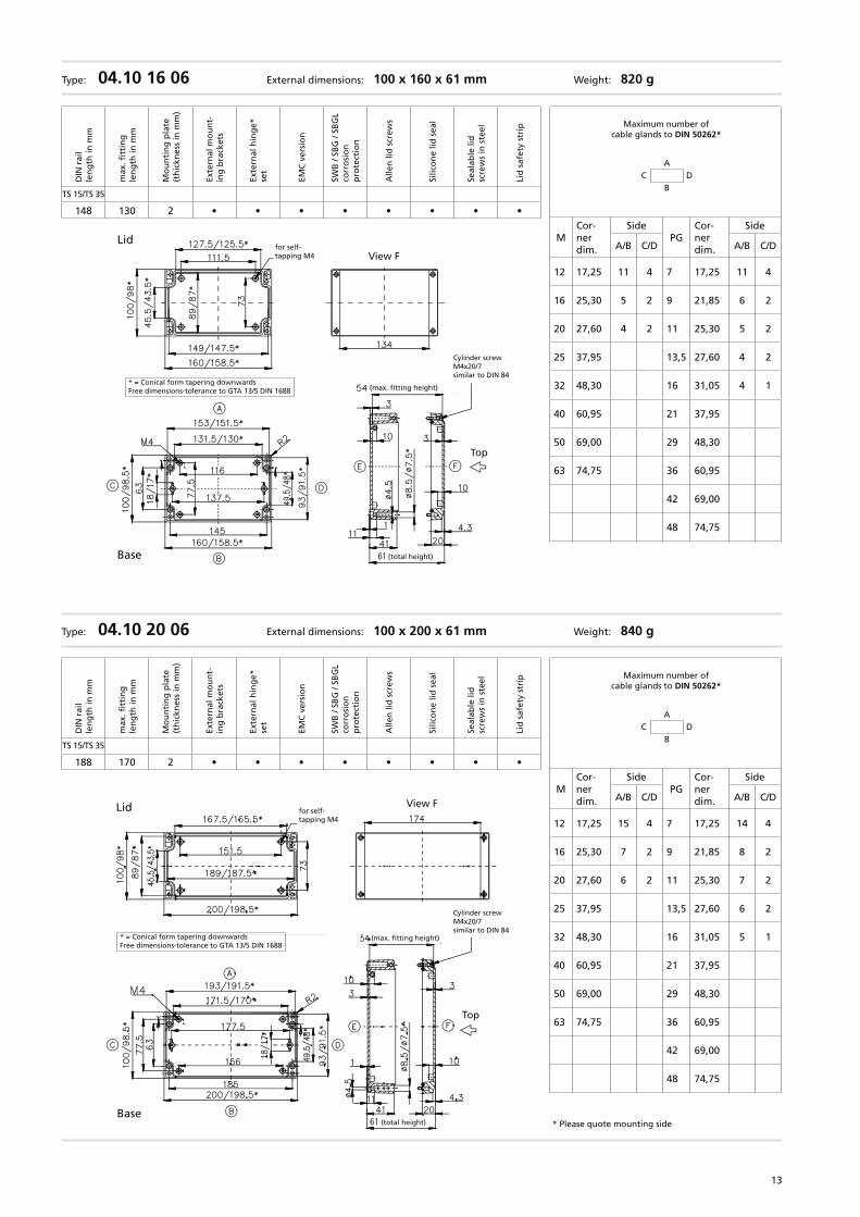
Type: 04.10 20 06 External dimensions: 100 x 200 x 61 mm Weight: 840 g
Lid
* = Conical form tapering downwardsFree dimensions-tolerance to GTA 13/5 DIN 1688
for self-tapping M4
View F
Cylinder screwM4x20/7similar to DIN 84
(max. fitting height)
(total height)
Top
Base
Maximum number of cable glands to DIN 50262*
C DA
B
MCor-ner dim.
SidePG
Cor-ner dim.
Side
A/B C/D A/B C/D
12 17,25 15 4 7 17,25 14 4
16 25,30 7 2 9 21,85 8 2
20 27,60 6 2 11 25,30 7 2
25 37,95 13,5 27,60 6 2
32 48,30 16 31,05 5 1
40 60,95 21 37,95
50 69,00 29 48,30
63 74,75 36 60,95
42 69,00
48 74,75
DIN
rai
lle
ng
th in
mm
max
. fitt
ing
le
ng
th in
mm
Mo
un
tin
g p
late
(t
hic
knes
s in
mm
)
Exte
rnal
mo
un
t-in
g b
rack
ets
Exte
rnal
hin
ge*
se
t
EMC
ver
sio
n
SWB
/ SB
G /
SBG
Lco
rro
sio
n
pro
tect
ion
Alle
n li
d s
crew
s
Silic
on
e lid
sea
l
Seal
able
lid
sc
rew
s in
ste
el
Lid
saf
ety
stri
p
TS 15/TS 35
188 170 2 • • • • • • • •
Type: 04.10 16 06 External dimensions: 100 x 160 x 61 mm Weight: 820 g
Base
Lid
* = Conical form tapering downwardsFree dimensions-tolerance to GTA 13/5 DIN 1688
for self-tapping M4 View F
Cylinder screwM4x20/7similar to DIN 84
(max. fitting height)
(total height)
Top
Maximum number of cable glands to DIN 50262*
C DA
B
MCor-ner dim.
SidePG
Cor-ner dim.
Side
A/B C/D A/B C/D
12 17,25 11 4 7 17,25 11 4
16 25,30 5 2 9 21,85 6 2
20 27,60 4 2 11 25,30 5 2
25 37,95 13,5 27,60 4 2
32 48,30 16 31,05 4 1
40 60,95 21 37,95
50 69,00 29 48,30
63 74,75 36 60,95
42 69,00
48 74,75
DIN
rai
lle
ng
th in
mm
max
. fitt
ing
le
ng
th in
mm
Mo
un
tin
g p
late
(t
hic
knes
s in
mm
)
Exte
rnal
mo
un
t-in
g b
rack
ets
Exte
rnal
hin
ge*
se
t
EMC
ver
sio
n
SWB
/ SB
G /
SBG
Lco
rro
sio
n
pro
tect
ion
Alle
n li
d s
crew
s
Silic
on
e lid
sea
l
Seal
able
lid
sc
rew
s in
ste
el
Lid
saf
ety
stri
p
TS 15/TS 35
148 130 2 • • • • • • • •
* Please quote mounting side
14
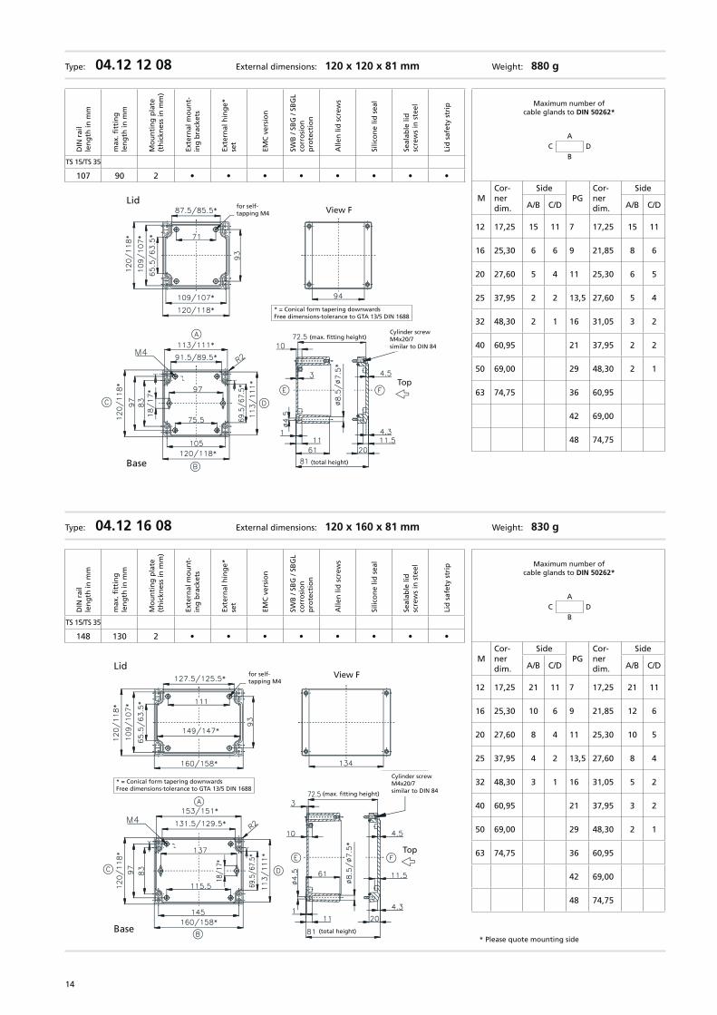
Type: 04.12 16 08 External dimensions: 120 x 160 x 81 mm Weight: 830 g
Base
Lid
* = Conical form tapering downwardsFree dimensions-tolerance to GTA 13/5 DIN 1688
for self-tapping M4
View F
Cylinder screwM4x20/7similar to DIN 84(max. fitting height)
(total height)
Top
Type: 04.12 12 08 External dimensions: 120 x 120 x 81 mm Weight: 880 g
Base
Lid
* = Conical form tapering downwardsFree dimensions-tolerance to GTA 13/5 DIN 1688
for self-tapping M4 View F
Cylinder screwM4x20/7similar to DIN 84
(max. fitting height)
(total height)
Top
Maximum number of cable glands to DIN 50262*
C DA
B
MCor-ner dim.
SidePG
Cor-ner dim.
Side
A/B C/D A/B C/D
12 17,25 15 11 7 17,25 15 11
16 25,30 6 6 9 21,85 8 6
20 27,60 5 4 11 25,30 6 5
25 37,95 2 2 13,5 27,60 5 4
32 48,30 2 1 16 31,05 3 2
40 60,95 21 37,95 2 2
50 69,00 29 48,30 2 1
63 74,75 36 60,95
42 69,00
48 74,75
DIN
rai
lle
ng
th in
mm
max
. fitt
ing
le
ng
th in
mm
Mo
un
tin
g p
late
(t
hic
knes
s in
mm
)
Exte
rnal
mo
un
t-in
g b
rack
ets
Exte
rnal
hin
ge*
se
t
EMC
ver
sio
n
SWB
/ SB
G /
SBG
Lco
rro
sio
n
pro
tect
ion
Alle
n li
d s
crew
s
Silic
on
e lid
sea
l
Seal
able
lid
sc
rew
s in
ste
el
Lid
saf
ety
stri
p
TS 15/TS 35
107 90 2 • • • • • • • •
Maximum number of cable glands to DIN 50262*
C DA
B
MCor-ner dim.
SidePG
Cor-ner dim.
Side
A/B C/D A/B C/D
12 17,25 21 11 7 17,25 21 11
16 25,30 10 6 9 21,85 12 6
20 27,60 8 4 11 25,30 10 5
25 37,95 4 2 13,5 27,60 8 4
32 48,30 3 1 16 31,05 5 2
40 60,95 21 37,95 3 2
50 69,00 29 48,30 2 1
63 74,75 36 60,95
42 69,00
48 74,75
DIN
rai
lle
ng
th in
mm
max
. fitt
ing
le
ng
th in
mm
Mo
un
tin
g p
late
(t
hic
knes
s in
mm
)
Exte
rnal
mo
un
t-in
g b
rack
ets
Exte
rnal
hin
ge*
se
t
EMC
ver
sio
n
SWB
/ SB
G /
SBG
Lco
rro
sio
n
pro
tect
ion
Alle
n li
d s
crew
s
Silic
on
e lid
sea
l
Seal
able
lid
sc
rew
s in
ste
el
Lid
saf
ety
stri
p
TS 15/TS 35
148 130 2 • • • • • • • •
* Please quote mounting side
15
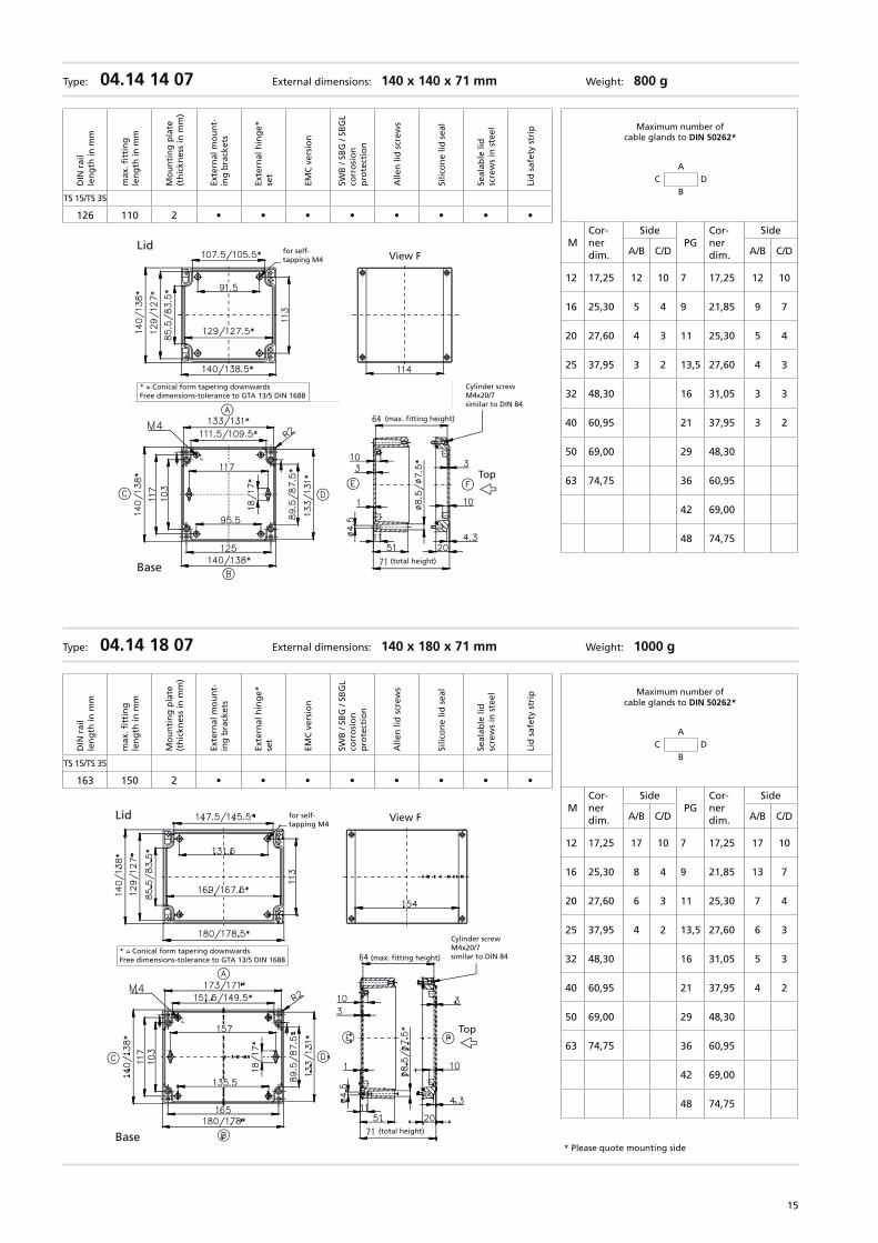
Type: 04.14 18 07 External dimensions: 140 x 180 x 71 mm Weight: 1000 g
* Please quote mounting sideBase
Lid
* = Conical form tapering downwardsFree dimensions-tolerance to GTA 13/5 DIN 1688
for self-tapping M4
View F
Cylinder screwM4x20/7similar to DIN 84(max. fitting height)
(total height)
Top
Maximum number of cable glands to DIN 50262*
C DA
B
MCor-ner dim.
SidePG
Cor-ner dim.
Side
A/B C/D A/B C/D
12 17,25 17 10 7 17,25 17 10
16 25,30 8 4 9 21,85 13 7
20 27,60 6 3 11 25,30 7 4
25 37,95 4 2 13,5 27,60 6 3
32 48,30 16 31,05 5 3
40 60,95 21 37,95 4 2
50 69,00 29 48,30
63 74,75 36 60,95
42 69,00
48 74,75
DIN
rai
lle
ng
th in
mm
max
. fitt
ing
le
ng
th in
mm
Mo
un
tin
g p
late
(t
hic
knes
s in
mm
)
Exte
rnal
mo
un
t-in
g b
rack
ets
Exte
rnal
hin
ge*
se
t
EMC
ver
sio
n
SWB
/ SB
G /
SBG
Lco
rro
sio
n
pro
tect
ion
Alle
n li
d s
crew
s
Silic
on
e lid
sea
l
Seal
able
lid
sc
rew
s in
ste
el
Lid
saf
ety
stri
p
TS 15/TS 35
163 150 2 • • • • • • • •
Type: 04.14 14 07 External dimensions: 140 x 140 x 71 mm Weight: 800 g
Lid
* = Conical form tapering downwardsFree dimensions-tolerance to GTA 13/5 DIN 1688
for self-tapping M4 View F
Cylinder screwM4x20/7similar to DIN 84
(max. fitting height)
(total height)
Top
Base
Maximum number of cable glands to DIN 50262*
C DA
B
MCor-ner dim.
SidePG
Cor-ner dim.
Side
A/B C/D A/B C/D
12 17,25 12 10 7 17,25 12 10
16 25,30 5 4 9 21,85 9 7
20 27,60 4 3 11 25,30 5 4
25 37,95 3 2 13,5 27,60 4 3
32 48,30 16 31,05 3 3
40 60,95 21 37,95 3 2
50 69,00 29 48,30
63 74,75 36 60,95
42 69,00
48 74,75
DIN
rai
lle
ng
th in
mm
max
. fitt
ing
le
ng
th in
mm
Mo
un
tin
g p
late
(t
hic
knes
s in
mm
)
Exte
rnal
mo
un
t-in
g b
rack
ets
Exte
rnal
hin
ge*
se
t
EMC
ver
sio
n
SWB
/ SB
G /
SBG
Lco
rro
sio
n
pro
tect
ion
Alle
n li
d s
crew
s
Silic
on
e lid
sea
l
Seal
able
lid
sc
rew
s in
ste
el
Lid
saf
ety
stri
p
TS 15/TS 35
126 110 2 • • • • • • • •
16
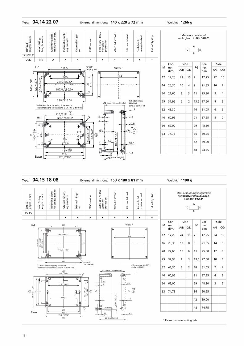
Type: 04.14 22 07 External dimensions: 140 x 220 x 72 mm Weight: 1266 g
Base
Lid
* = Conical form tapering downwardsFree dimensions-tolerance to GTA 13/5 DIN 1688
for self-tapping M4 View F
Cylinder screwM4x20/7similar to DIN 84
(max. fitting height)
(total height)
Top
Maximum number of cable glands to DIN 50262*
C DA
B
MCor-ner dim.
SidePG
Cor-ner dim.
Side
A/B C/D A/B C/D
12 17,25 22 10 7 17,25 22 10
16 25,30 10 4 9 21,85 16 7
20 27,60 8 3 11 25,30 9 4
25 37,95 5 2 13,5 27,60 8 3
32 48,30 16 31,05 6 3
40 60,95 21 37,95 5 2
50 69,00 29 48,30
63 74,75 36 60,95
42 69,00
48 74,75
DIN
rai
lle
ng
th in
mm
max
. fitt
ing
le
ng
th in
mm
Mo
un
tin
g p
late
(t
hic
knes
s in
mm
)
Exte
rnal
mo
un
t-in
g b
rack
ets
Exte
rnal
hin
ge*
se
t
EMC
ver
sio
n
SWB
/ SB
G /
SBG
Lco
rro
sio
n
pro
tect
ion
Alle
n li
d s
crew
s
Silic
on
e lid
sea
l
Seal
able
lid
sc
rew
s in
ste
el
Lid
saf
ety
stri
p
TS 15/TS 35
206 190 2 • • • • • • • •
Type: 04.15 18 08 External dimensions: 150 x 180 x 81 mm Weight: 1100 g
* Please quote mounting side
Max. Bestückungsmöglichkeit für Kabelverschraubungen
nach DIN 50262*
C DA
B
MCor-ner dim.
SidePG
Cor-ner dim.
Side
A/B C/D A/B C/D
12 17,25 24 15 7 17,25 24 15
16 25,30 12 8 9 21,85 14 9
20 27,60 10 6 11 25,30 12 8
25 37,95 4 3 13,5 27,60 10 6
32 48,30 3 2 16 31,05 7 4
40 60,95 21 37,95 4 3
50 69,00 29 48,30 3 2
63 74,75 36 60,95
42 69,00
48 74,75
DIN
rai
lle
ng
th in
mm
max
. fitt
ing
le
ng
th in
mm
Mo
un
tin
g p
late
(t
hic
knes
s in
mm
)
Exte
rnal
mo
un
t-in
g b
rack
ets
Exte
rnal
hin
ge*
se
t
EMC
ver
sio
n
SWB
/ SB
G /
SBG
Lco
rro
sio
n
pro
tect
ion
Alle
n li
d s
crew
s
Silic
on
e lid
sea
l
Seal
able
lid
sc
rew
s in
ste
el
Lid
saf
ety
stri
p
TS 15
• • • • • • • •
Deckel
139
/ 13
7,4*
147,5 / 146*
169 / 167,8*
180
95,5
/ 94
,2*
150
/ 14
8*
131
123
* = Maß durch Formkonizität nach unten verringert Freimaß - Toleranz nach GTA13/5 DIN 1688
f. Schneid-schraube M4
151,5 / 149,5*
173 / 171*
99,5
/ 97
,6*
143
141
*
135,5
157165
113
127
17 /
18*
179,9 / 177,8*
135
149,
9 /
147,
8*
R 2
R 2Unterteil
B
D
A
C
1
116181 (Gesamthöhe)
4,3
11,5
4,5
8,5
/ 7,
5*
310
72,5 (max. Einbauhöhe)
4,5
Oben
Zyl.-schraubeM4x20/7 ähnl. DIN84
E F
154
Ansicht FLid
* = Conical form tapering downwardsFree dimensions-tolerance to GTA 13/5 DIN 1688
for self-tapping M4
View F
(max. fitting height)
(total height)
Top
Cylinder screw M4x20/7similar to DIN 84
Base
17
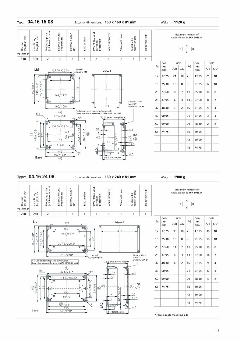
Type: 04.16 16 08 External dimensions: 160 x 160 x 81 mm Weight: 1120 g
Type: 04.16 24 08 External dimensions: 160 x 240 x 81 mm Weight: 1900 g
* Please quote mounting side
Lid
* = Conical form tapering downwardsFree dimensions-tolerance to GTA 13/5 DIN 1688
for self-tapping M4
View F
Cylinder screwM4x20/7similar to DIN 84
(max. fitting height)
(total height)
Top
Base
Lid
* = Conical form tapering downwardsFree dimensions-tolerance to GTA 13/5 DIN 1688
for self-tapping M4 View F
Cylinder screwM4x20/7similar to DIN 84
(max. fitting height)
(total height)
Top
Base
Maximum number of cable glands to DIN 50262*
C DA
B
MCor-ner dim.
SidePG
Cor-ner dim.
Side
A/B C/D A/B C/D
12 17,25 21 18 7 17,25 21 18
16 25,30 10 8 9 21,85 12 10
20 27,60 8 7 11 25,30 10 8
25 37,95 4 3 13,5 27,60 8 7
32 48,30 3 2 16 31,05 5 4
40 60,95 21 37,95 3 3
50 69,00 29 48,30 2 2
63 74,75 36 60,95
42 69,00
48 74,75
DIN
rai
lle
ng
th in
mm
max
. fitt
ing
le
ng
th in
mm
Mo
un
tin
g p
late
(t
hic
knes
s in
mm
)
Exte
rnal
mo
un
t-in
g b
rack
ets
Exte
rnal
hin
ge*
se
t
EMC
ver
sio
n
SWB
/ SB
G /
SBG
Lco
rro
sio
n
pro
tect
ion
Alle
n li
d s
crew
s
Silic
on
e lid
sea
l
Seal
able
lid
sc
rew
s in
ste
el
Lid
saf
ety
stri
p
TS 15/TS 35
148 130 2 • • • • • • • •
Maximum number of cable glands to DIN 50262*
C DA
B
MCor-ner dim.
SidePG
Cor-ner dim.
Side
A/B C/D A/B C/D
12 17,25 36 18 7 17,25 36 18
16 25,30 16 8 9 21,85 18 10
20 27,60 14 7 11 25,30 16 8
25 37,95 6 3 13,5 27,60 14 7
32 48,30 4 2 16 31,05 9 4
40 60,95 21 37,95 6 3
50 69,00 29 48,30 4 2
63 74,75 36 60,95
42 69,00
48 74,75
DIN
rai
lle
ng
th in
mm
max
. fitt
ing
le
ng
th in
mm
Mo
un
tin
g p
late
(t
hic
knes
s in
mm
)
Exte
rnal
mo
un
t-in
g b
rack
ets
Exte
rnal
hin
ge*
se
t
EMC
ver
sio
n
SWB
/ SB
G /
SBG
Lco
rro
sio
n
pro
tect
ion
Alle
n li
d s
crew
s
Silic
on
e lid
sea
l
Seal
able
lid
sc
rew
s in
ste
el
Lid
saf
ety
stri
p
TS 15/TS 35
228 210 2 • • • • • • • •
18
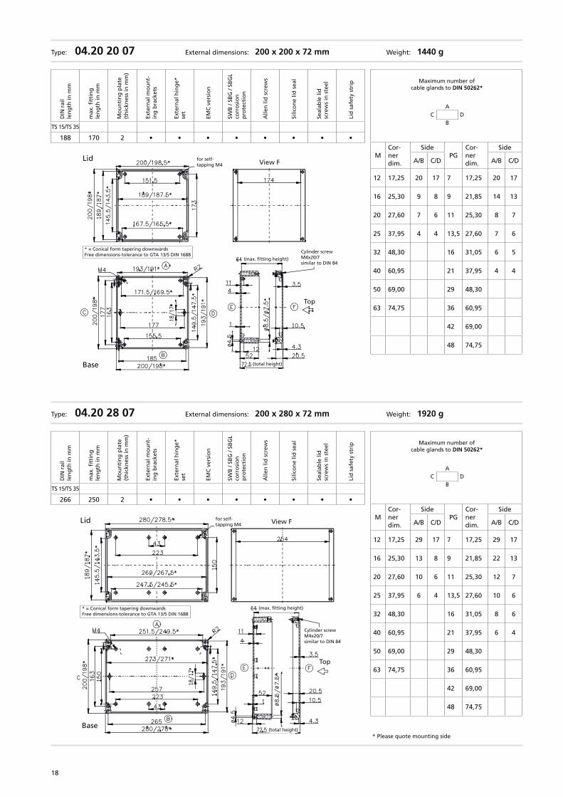
Type: 04.20 20 07 External dimensions: 200 x 200 x 72 mm Weight: 1440 g
Type: 04.20 28 07 External dimensions: 200 x 280 x 72 mm Weight: 1920 g
* Please quote mounting side
Base
Lid
* = Conical form tapering downwardsFree dimensions-tolerance to GTA 13/5 DIN 1688
for self-tapping M4 View F
Cylinder screwM4x20/7similar to DIN 84
(max. fitting height)
(total height)
Top
Lid
* = Conical form tapering downwardsFree dimensions-tolerance to GTA 13/5 DIN 1688
for self-tapping M4 View F
Cylinder screwM4x20/7similar to DIN 84
(max. fitting height)
(total height)
Top
Base
Maximum number of cable glands to DIN 50262*
C DA
B
MCor-ner dim.
SidePG
Cor-ner dim.
Side
A/B C/D A/B C/D
12 17,25 20 17 7 17,25 20 17
16 25,30 9 8 9 21,85 14 13
20 27,60 7 6 11 25,30 8 7
25 37,95 4 4 13,5 27,60 7 6
32 48,30 16 31,05 6 5
40 60,95 21 37,95 4 4
50 69,00 29 48,30
63 74,75 36 60,95
42 69,00
48 74,75
DIN
rai
lle
ng
th in
mm
max
. fitt
ing
le
ng
th in
mm
Mo
un
tin
g p
late
(t
hic
knes
s in
mm
)
Exte
rnal
mo
un
t-in
g b
rack
ets
Exte
rnal
hin
ge*
se
t
EMC
ver
sio
n
SWB
/ SB
G /
SBG
Lco
rro
sio
n
pro
tect
ion
Alle
n li
d s
crew
s
Silic
on
e lid
sea
l
Seal
able
lid
sc
rew
s in
ste
el
Lid
saf
ety
stri
p
TS 15/TS 35
188 170 2 • • • • • • • •
Maximum number of cable glands to DIN 50262*
C DA
B
MCor-ner dim.
SidePG
Cor-ner dim.
Side
A/B C/D A/B C/D
12 17,25 29 17 7 17,25 29 17
16 25,30 13 8 9 21,85 22 13
20 27,60 10 6 11 25,30 12 7
25 37,95 6 4 13,5 27,60 10 6
32 48,30 16 31,05 8 6
40 60,95 21 37,95 6 4
50 69,00 29 48,30
63 74,75 36 60,95
42 69,00
48 74,75
DIN
rai
lle
ng
th in
mm
max
. fitt
ing
le
ng
th in
mm
Mo
un
tin
g p
late
(t
hic
knes
s in
mm
)
Exte
rnal
mo
un
t-in
g b
rack
ets
Exte
rnal
hin
ge*
se
t
EMC
ver
sio
n
SWB
/ SB
G /
SBG
Lco
rro
sio
n
pro
tect
ion
Alle
n li
d s
crew
s
Silic
on
e lid
sea
l
Seal
able
lid
sc
rew
s in
ste
el
Lid
saf
ety
stri
p
TS 15/TS 35
266 250 2 • • • • • • • •
19
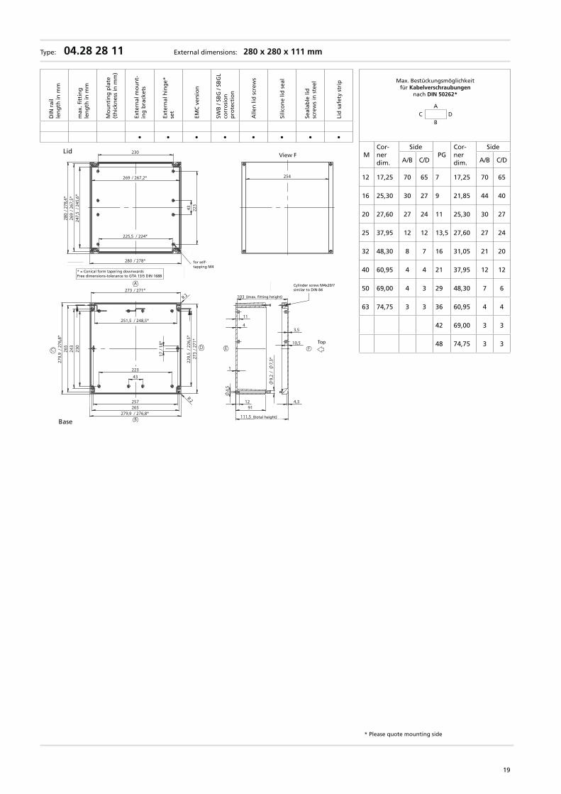
Max. Bestückungsmöglichkeit für Kabelverschraubungen
nach DIN 50262*
Type: 04.28 28 11 External dimensions: 280 x 280 x 111 mm
* Please quote mounting side
C DA
B
MCor-ner dim.
SidePG
Cor-ner dim.
Side
A/B C/D A/B C/D
12 17,25 70 65 7 17,25 70 65
16 25,30 30 27 9 21,85 44 40
20 27,60 27 24 11 25,30 30 27
25 37,95 12 12 13,5 27,60 27 24
32 48,30 8 7 16 31,05 21 20
40 60,95 4 4 21 37,95 12 12
50 69,00 4 3 29 48,30 7 6
63 74,75 3 3 36 60,95 4 4
42 69,00 3 3
48 74,75 3 3
DIN
rai
lle
ng
th in
mm
max
. fitt
ing
le
ng
th in
mm
Mo
un
tin
g p
late
(t
hic
knes
s in
mm
)
Exte
rnal
mo
un
t-in
g b
rack
ets
Exte
rnal
hin
ge*
se
t
EMC
ver
sio
n
SWB
/ SB
G /
SBG
Lco
rro
sio
n
pro
tect
ion
Alle
n li
d s
crew
s
Silic
on
e lid
sea
l
Seal
able
lid
sc
rew
s in
ste
el
Lid
saf
ety
stri
p
• • • • • • • •
Oben
251,5 / 248,5*
273 / 271*
243
230
265
43223
257
229,
5 /
226,
5*27
3 /
271*
279,9 / 276,8*265
279,
9 /
276,
8*
17 /
18*
R 2
R 2Unterteil
A
B
C D
11
4
4,5
1
1291
111,5 (Gesamthöhe)
4,3
10,5
3,5
9,2
/ 7,
3*
103 (max Einbauhöhe)
Zyl.-schraubeM4x20/7 ähnl. DIN84
E F
247,
5 /
245,
6*26
9 /
267,
5*
43 223
230
269 / 267,2*
225,5 / 224*
280 / 278*
280
/ 27
8,4*
Deckel
* = Maß durch Formkonizität nach unten verringert Freimaß - Toleranz nach GTA13/5 DIN 1688
f. Schneid-schraube M4
254
Ansicht F
Base
Lid
* = Conical form tapering downwardsFree dimensions-tolerance to GTA 13/5 DIN 1688
for self-tapping M4
View F
(max. fitting height)
(total height)
Top
Cylinder screw M4x20/7similar to DIN 84


![Index [docs.rs-online.com]](https://img.pdfslide.us/doc/110x75/62036fa806a66a2c2a386228/index-docsrs-.jpg)