Embed Size (px)
Citation preview

ALTERNATIVE DEEP BASEMENT SOLUTIONS FOR BUILT- UP AREAS Abid Adekunte, Deep Foundations Specialists, U.K. John Bullock, Deep Foundations Specialists, U.K. In recent years, developers have had to deal with complexities associated with numerous cases of deep basement construction in built-up areas. Design and construction of deep excavation support systems in urbanised zones come with many technical challenges. Restricted working spaces often render the use of temporary struts as wall restraint systems unpopular, as working space needs to be maximised. Also, tie-back anchors are often inapplicable due to the existence of adjacent structures. Therefore, developing alternative restraint systems for deep basement structures in built-up areas is becoming increasingly important to the present day basement engineer. This paper is centred on the design, construction and monitoring of enabling works for deep basement structures on three sites in the United Kingdom and Republic of Ireland. Traditional tie-back anchorage and propping systems were inapplicable on the sites. As alternatives, separate novel wall restraint systems were developed and adopted, to enable excavation on each of the three sites. Performances of the novel wall restraint systems, as well as the responses of adjacent structures were monitored. Numerical modelling and field monitoring results show the three alternative wall restraint systems to be safe and effective. The paper also highlights the advantages of the novel solutions over conventional methods. INTRODUCTION Recently, deep basement structures have become popular components of urban building developments. As pointed out by Pearlman et al., 2004, this could be attributed to the inadequacy of surface parking spaces in urbanised zones, while underground parking facilities are also believed to improve both aesthetic and commercial qualities of urban structures. However, while the incorporation of basement structure into new urban development appeals to developers and architects, the engineering design and construction aspects of basement works typically come against a whole lot of complexities and challenges. As highlighted by Wong, 2002, engineering problems associated with basement construction in built-up areas are numerous, some of these include; complicated sub-soil conditions, dealing with excessive active pressures, complex temporary works, proximity of sensitive adjacent structures, high level hazards to construction workmen and surrounding community, inadequate working space, etc. Over the years, urban basement engineers have favoured reinforced concrete diaphragm wall as the ideal excavation support system for buildings with deep basements, especially where groundwater cut-off is required. They are considered to provide higher structural stiffness and resistance to ground movement, when
compared with other types of embedded retaining walls (Clough & O’Rourke, 1990; Pearlman et al., 2004). However, the construction of a diaphragm wall requires a sizeable working space to accommodate bentonite plants and reinforcement cage fabrication areas. As construction sites in built-up areas are often congested, adoption of diaphragm walls on urban projects has often been problematic. Also, many consider the diaphragm wall installation process to be relatively slow. In recent years, pile retaining walls are increasingly becoming popular alternatives to diaphragm walls on urban development projects. While their applications are limited by construction tolerances (especially verticality) and embedment depth, they are relatively more economical and faster to install. Many publications on case histories of pile retaining walls abound in the literature e.g. Adekunte, 2007; Looby & Long, 2007; Byrne, 2007; Finno & Bryson, 2002; Dougan et al., 1996 and Watson & Carder, 1994. On basement projects where groundwater cut-off is not required, contiguous pile wall is a common choice. In order to limit ground movement and associated serviceability problems on adjacent structures in built-up areas, pile retaining walls are traditionally provided with additional restraint in the form of props or anchors.
ADEKUNTE, A & BULLOCK, J (2013). ‘Alternative Deep Basement Solutions for Built-Up Areas’. Paper Presented & Published in the Proceedings of the Deep Foundations Institute’s 38th Annual Conference on Deep Foundations, Phoenix Arizona, USA, September 25-28, 2013.

The conventional practice of restraining embedded retaining walls with props and anchors is well established and several publications on these abound in the literature e.g. Loveridge, 2001; Batten & Powrie, 2000a & 2000b; Richards et al., 1999; Twine & Roscoe, 1999; Batten, 1998; Carder et al., 1997; Potts & Bond, 1994; Symons et al., 1987 and Milligan, 1983. However, in recent years, due to frequent cases of limited working spaces and presence of adjacent sensitive underground and above-ground structures, the application of props and anchors as restraint systems for pile retaining walls on urban projects is becoming limited. As a result of this, a number of workers are concentrating on the development and application of alternative methods of restraining pile retaining walls in built-up areas e.g. Adekunte, 2011; Adekunte et al., 2010; Adekunte, 2008 and Deschamps et al., 2008. This paper focuses on the analysis, design, construction and monitoring of contiguous pile retaining walls on three separate sites in different ground conditions. Site constraints led engineers to the innovation and application of rare alternative wall restraint systems on the sites. Details are presented in the following sections. SITE GEOLOGY This study is centred on three sites; site 1, site 2 and site 3. Site 1 is located in southeast England, site 2 is located on the east coast of Ireland, while site 3 is located in north central Ireland. Stratigraphy on site 1 comprises of made ground overlying Taplow gravel formation, which is underlain by London clay to 17m depth. The Taplow gravel formation comprises of loose to medium dense to dense clayey very sandy gravel and locally contains silt lenses. The underlying London clay comprises of firm to stiff to very stiff bluish grey slightly sandy silty clay. Ground conditions on sites 2 and 3 mainly comprise of made ground and medium dense gravel overlying Irish glacial till. Irish glacial till is a mixed material comprising of gravels, cobbles, sand and clay-sized particles randomly mixed, resulting from movement and subsequent deposition by glacier ice with little or no sorting by water. Grading curves for Irish glacial till on sites 2 & 3 are compared with those of samples from other parts of Ireland in figure 1. The figure shows a degree of consistency in the particle
size distribution of the Irish glacial till, regardless of location. The main similarity between the Irish glacial till and London clay is that they are both overconsolidated materials of low permeability. The London clay on site 1 is of high plasticity, with plasticity indices ranging between 31% - 40% and liquid limit ranging between 55% - 65%. Samples of Irish glacial till on sites 2 & 3 are of low to intermediate plasticity with plasticity indices varying between 10% - 25%. Figures 2a, 2b & 2c show generalised ground conditions on sites 1, 2 and 3 respectively in relation to the excavation support system on each site. Geotechnical design parameters for sites 1, 2 and 3 are presented in tables 1a, 1b and 1c respectively. In order to allow for the effect of remoulding and stress relief that occur in soils during wall installation and excavation, coefficients of earth pressure Ko for the overconsolidated materials were limited to 1.0 in accordance with CIRIA Report No. C580, 2003. With regards to numerical modelling, London clay on site 1 and Irish glacial till on site 2 were modelled as undrained materials (with total stress parameters) in the temporary condition, while they were assumed to exhibit drained behaviour in the permanent condition (after CIRIA Report No. C580, 2003). However, the Irish glacial till on site 3 was modelled with effective stress parameters for both temporary and permanent conditions, in accordance with the supervising engineers’ specification; this approach appears to be quite conservative (see Adekunte, 2008). Coefficients of active and passive pressures were taken off Caquot & Kerisel’s (1984) chart. In accordance with CIRIA Report No. 104, 1984 and CIRIA Report No. C580, 2003, effective wall friction angles
equivalent to 0.67 and 0.5 were assumed for the active and passive sides respectively. SITE 1 Proposed Development: The project on site 1 was centred on the redevelopment of a site previously occupied by a cinema in Enfield, which is located 14 miles to the north of London. It was proposed to demolish the existing cinema structure and redevelop the site with a mixed residential/commercial building, comprising of 39 homes and 6 commercial units.

Figure 1 - Comparison of grading curves for site 2 and site 3 with samples from other parts of Ireland
(after Hanrahan, 1977).
Figure 2a – Site 1 stratigraphy in relation to the excavation support system on the site.
Wall toe level: 91.0m AD
600 contiguous pile
wall, piles @ 750mm c/c
Buttress pile toe level: 90.0m AD
1.0m
96.0m AD
98.5m AD
0
20
40
60
80
100
120
0.001 0.01 0.1 1 10 100
Pe
rce
nta
ge
Fin
er
(%)
Particle Size (mm)
Cork Claire
Cavan Waterford
Meath Site 2
Sligo Site 3
0.063
Static groundwater level: 94.0m AD
1.0m
H = 5.0m
Formation level: 95.0m AD
MADE GROUND, Nspt = 8 - 12
Existing ground level 100.0m AD
Continuous RC
capping beam
on pile wall
600 vertical buttress piles,
piles @ 5m intervals along
wall perimeter
FIRM TO STIFF LONDON CLAY, Nspt = 15 - 30
LOOSE TO MEDIUM DENSE GRAVEL, Nspt = 10 - 15
0.75m
RC capping beam on buttress piles @ 5m
intervals
Building surcharge

Figure 2b – Site 2 stratigraphy in relation to the excavation support system on the site.
Nspt – Average corrected standard penetration test N value, R* - Refusal. Figure 2c – Site 3 stratigraphy in relation to the excavation support system on the site.
Static ground water level: -4.0m AD
2.5m
B20 dowel bars @ every
pile position
H = 6.0m - 7.0m
Formation level –7.0m AD
MADE GROUND (0.0 m AD to – 1.5m AD), Nspt = 12
MEDIUM DENSE GRAVEL (-1.5 m AD to – 4.0m AD), Nspt = 15
Existing ground level 0.0m AD
Pile Toe level -11.5m AD
RC capping
beam
600 contiguous pile
wall, piles @ 750mm c/c
Restraining structure;
lightly reinforced
concrete counterweight
STIFF SANDY CLAY (-4.0 m AD to – 19.0m AD), Nspt = 15
Building & traffic surcharges
H = 7.5m
100
Formation level +93.9m OD
FIRM SANDY CLAY (101.4 m OD – 99.9 m OD), Nspt = 13
STIFF TO VERY STIFF GRAVELLY CLAY (99.9 m OD – 81.4 m OD), Nspt = 35
Existing ground level +101.4m OD
Wall Toe level +89.4m OD
RC capping
beam
600 contiguous pile
wall, piles @ 675mm c/c
LIMESTONE BEDROCK (Below 81.4 m OD), Nspt = R*
600 raking buttress
piles @ 2m c/c
Static water level: +87.4m OD
Buttress Pile Toe level +86.6m OD

Table 1a – Geotechnical design parameters for site 1
Stratum Bulk
Density (kN/m
3)
E50ref
(kPa) Eoed
ref
(kPa) Eur
ref (kPa) Undrained
Strength Cu (kPa)
Angle of Shearing
Resistance
()
Coefficient of Earth Pressure Ko
Made Ground
18.0 20000 20000 60000 - 30.0 (C’ = 0) 0.5
Loose to Medium Dense Gravel
19.0 40000 40000 120000 - 33.0 (C’ = 0) 1.0
Firm to Stiff London Clay
19.0 40000 40000 120000 100.0 25.0 (C’ = 3.0) 1.0
E50
ref = secant stiffness in standard triaxial test, Eoed
ref = tangent stiffness for primary oedometer loading,
Eurref
= unloading/reloading stiffness.
Table 1b – Geotechnical design parameters for site 2
Stratum
Bulk density
(kN/m
3)
Young’s modulus E (kPa)
Undrained Strength Cu
(kPa)
Angle of shearing
resistance ’ ()
Coefficient of earth pressure Ko
Made Ground
18.0 30000 - 30.0 0.5
Medium Dense Gravel
19.0 40000 - 32.0 1.0
Stiff Sandy Clay
19.0 40000 75.0 32.0 1.0
Table 1c – Geotechnical design parameters for site 3
Stratum
Bulk
density (kN/m
3)
Young’s modulus E
(kPa)
Angle of shearing
resistance ’ ()
Assumed coefficient of earth
pressure Ko
Skin friction resistance fs
(kPa)
Firm sandy clay
18.0 32000 30.0 1.0 50.0
Stiff to very stiff gravelly clay
20.0 87000 37.0 1.0 110.0
All homes were designed to achieve Level 3 of the code for sustainable homes (2010). An underground car park was incorporated into the proposed scheme and this required the construction of a 5m high contiguous pile wall for temporary and permanent earth retention. As the development was located in a built-up area, a number of wall sections were subject to structural surcharge loads from adjacent buildings. In order to limit ground and structural
movement, while maintaining overall stability, it was necessary to provide these wall sections with additional restraint. Ground anchors could not be installed due to the close proximity of existing structures. Also, due to inadequate working space, the use of temporary props was not supported by the main contractor. As an alternative solution, the wall was supported with a rare restraint system comprising of vertical buttress piles installed behind the wall in rows

perpendicular to the wall line. Each row of buttress piles comprised of 2 No. CFA-bored piles, while rows were spaced at 5m intervals. Figure 3 shows a typical layout of the wall-buttress pile system. The contiguous pile wall and buttress piles were rigidly connected by reinforced concrete capping beams. Construction Procedure: Stages involved in the construction of the earth retention system on site 1 are outlined in table 2. Same sequence was followed in numerical modelling. Piles were installed by continuous flight auger (CFA) boring with a SoilMec SF50 hydraulic piling rig. 600mm diameter piles were installed at 750mm c/c spacing to form the contiguous pile wall. Wall buttress system was installed with same piling rig. Buttress system comprised of
5m-spaced rows of piles at 90 angle to the back of the contiguous wall. Each row comprised of 2
No. 600 piles spaced @ 1m c/c. These provide additional lateral rigidity to the pile retaining wall. An initial excavation was carried out to 750mm depth around pile wall and buttress piles, to allow for the construction of reinforced concrete capping beams for the pile wall and buttress piles. Construction of capping beams was followed by the completion of excavation to formation level in front of wall and subsequent construction of the permanent RC floor slabs and liner wall. Figure 3 – Layout of contiguous pile wall and buttress piles on site 1.
Figure 4a shows the completed wall-buttress system, while figure 4b shows the basement structure during construction. As groundwater level lied below basement formation level, groundwater control was not an issue during construction.
Figure 4a – Site 1: typical wall-buttress system.
Figure 4b – Site 1: basement structure under construction.
600 contiguous pile
wall; 600 piles @
750mm c/c
750mm deep RC capping
beam on contiguous pile wall
600 vertical
buttress piles
750mm deep RC capping
beams on buttress piles
0.8m
0.8m
1.0m
5.0m
Excavation Area
Line of Wall
Line of Buttress

Table 2 – Construction sequence on site 1
Stage No. Description of works
1 Install Ø600 CFA-bored piles @ 750mm c/c spacing to form contiguous pile wall
2 Install rows of vertical buttress piles behind wall at 90 angle to wall line, spaced
@ 5m intervals. Each row comprising of 2 No. 600 CFA-bored piles @ 1m c/c spacing and aligned perpendicularly to contiguous wall.
3 Excavate soil around piles to 750mm depth and construct RC capping beams to connect contiguous pile wall to buttress piles.
4 Complete excavation to basement formation level.
5 Construct basement and ground floor slabs and permanent RC liner wall.
Numerical Analysis & Wall Design: The wall was designed to be restrained at intervals by a system of twin vertical buttress piles connected by a capping beam. Numerical analysis and design involved the following;
overall stability analysis of the contiguous pile wall/buttress system;
serviceability analysis of the contiguous pile wall/buttress system;
structural design for the contiguous pile wall;
geotechnical and structural design for the vertical buttress piles;
o axial capacity in compression; o axial capacity in tension; o lateral capacity check; o tension reinforcement design;
tendon capacity check, tendon-concrete bond capacity check.
o bending reinforcement design; o shear reinforcement design;
structural design for the capping beam on buttress piles;
structural design for the capping beam on contiguous pile wall.
The made ground and medium dense gravel layers were modelled with effective stress parameters. In accordance with recommendations in CIRIA Report No. C580, 2003 and CIRIA Report No. 104, 1984, the firm to stiff London clay stratum was modelled as an undrained material in the temporary condition, while it was assumed to exhibit drained behaviour in the permanent condition. 50% wall relaxation was also considered in the permanent condition to account for the additional displacements and stresses that may result from long term reduction in wall stiffness.
Overall Stability Analysis An ultimate limit state approach was adopted for overall stability analysis. Factored soil parameters and loads were used to estimate the required depth of wall embedment for global stability to be maintained. The total stress parameters and effective stress parameters shown in table 1a were reduced with safety factors of 1.5 and 1.25 respectively, in accordance with CIRIA report No. C580’s (2003) recommendations for moderately conservative design approach. Unfavourable loads were also factored up with a safety factor of 1.5. Analysis was done with ‘Oasys STAWAL’ geotechnical limit equilibrium modelling programme. Required wall toe depth was estimated to be 9m (measured from piling platform level); this corresponds to a minimum embedment of 4m below basement formation level. Serviceability Analysis Serviceability analysis was carried out with PLAXIS 2D 2012 geotechnical finite element modelling programme for soil-structure interaction. Using unfactored soil parameters and loads, estimates of ground and structural movements, as well as forces and bending moments on the wall and buttress system were computed. A plane strain model with a very fine mesh comprising of 15-node wedge elements was deemed to be appropriate for the required level of accuracy and precision. Boundary conditions were carefully chosen to minimise their influence on wall behaviour and associated ground response. Soil layers were represented with Hardening Soil (HS) model, as this accounts for the stress-dependency of soil stiffness and thus model soil response to unloading better than conventional
mohr-coulomb model. While the HS model uses a mohr-coulomb yield surface, it accounts for hardening plasticity within the failure envelope (i.e. pre-failure stress state). Dilatancy was taken into consideration, while the state of critical density was also accounted for by adopting a dilatancy cut-off where maximum dilatancy is experienced by the soil at its maximum porosity. As the excavation support involved a rare wall restraint system, numerical modelling involved a relatively significant level of sensitivity analysis, to assess the influence of potential variations in geotechnical and structural parameters on wall behaviour. While soil model is fundamentally important to the level of accuracy of predicted wall performance, in this particular case, the designers also considered the RC capping beams on both the contiguous wall and the buttress piles to have considerable influence on the overall effectiveness of the wall-buttress system. Therefore, the designers concentrated on assessing the sensitivity of predicted wall behaviour to the models adopted for the RC capping beams. The finite element modelling programme (PLAXIS 2D 2012) allows structural elements to be modelled in 3 ways; (i) as volume elements; (ii) as beam elements; (iii) as struts. However, options (i) & (ii) were considered to be more appropriate. Finite element analysis results show the behaviour of the buttress system to be based on a push-pull mechanism; one pile experiences compression only, while the other pile is subject to some tensile forces in addition to axial compression. For this reason, the toe levels of buttress piles were designed to be lower than the toe level of wall, so that compressive loading on the buttress piles do not contribute additional surcharge loads to the wall. FE analysis results also show the RC capping beam on buttress piles to be subject to tension, bending moment and shear, while the capping beam on contiguous wall is subject to shear, bending and torsion. Structural Design for Wall & Buttress Piles Structural design for the contiguous pile wall accounted for the bending moments and shear forces induced in the piles, as well as the torsion, bending moments and shear forces in the capping beam on the wall. Structural design for the buttress piles accounted for tension, compression, shear forces and bending
moments induced in the piles, as well as axial tension, shear forces and bending moments in the capping beam on the piles. Structural design was carried out in accordance with BS 8110-1: 1997, using ‘Oasys AdSec’ structural modelling programme. Wall Monitoring: Wall deflection on site 1 was monitored by optical survey. In addition to wall movement, the vertical displacements of existing adjacent structures were monitored with tiltmeters. Wall monitoring procedure is outlined below;
After wall and buttress system construction, shot-fix nails were installed as targets at selected positions on capping beams.
Initial coordinates of targets were recorded with survey instrument.
After recording initial coordinates, coordinate readings were taken at 1 working day-interval during excavation and every two weeks after completion of excavation.
Monitoring was carried out over a period of 4 months; only two additional readings were recorded after ground floor slab construction, as no significant movement was observed after slabs were constructed.
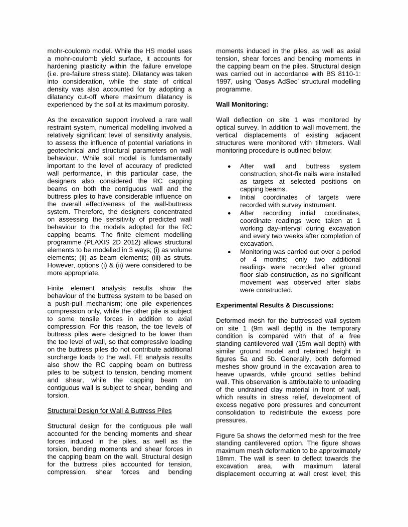
Experimental Results & Discussions: Deformed mesh for the buttressed wall system on site 1 (9m wall depth) in the temporary condition is compared with that of a free standing cantilevered wall (15m wall depth) with similar ground model and retained height in figures 5a and 5b. Generally, both deformed meshes show ground in the excavation area to heave upwards, while ground settles behind wall. This observation is attributable to unloading of the undrained clay material in front of wall, which results in stress relief, development of excess negative pore pressures and concurrent consolidation to redistribute the excess pore pressures. Figure 5a shows the deformed mesh for the free standing cantilevered option. The figure shows maximum mesh deformation to be approximately 18mm. The wall is seen to deflect towards the excavation area, with maximum lateral displacement occurring at wall crest level; this

consequently results in significant ground settlement directly behind wall. In similarity with figure 5a, the deformed mesh for the buttressed wall option also shows ground in front of wall to heave upwards, with ground behind wall settling (see figure 5b). In figure 5b, ground settlement behind the wall is observed to cause a drag-down effect on the buttress piles. The drag-down effect results in the capping beam deflecting slightly away from the excavation area in the direction of ground movement. The figure also shows the capping beam to be effective at making the wall and buttress piles act as a single unit. In comparison with the free standing cantilevered option, maximum mesh deformation is more than 50% less, wall crest does not deflect towards excavation area, while ground settlement directly behind wall is less significant. Figure 5c shows the lateral deflection profile of the free standing cantilevered wall. Maximum lateral deflection of 16mm occurs at wall crest level. On the other hand, figure 5d shows the lateral deflection profile of the buttressed wall; maximum lateral deflection of approximately 8mm occurs around mid-height of wall, with lowest movement of 6mm occurring at wall crest level; this could be attributed to the restraining effect of the buttress piles. Comparing both solutions in terms of required wall depth for overall stability and lateral deflection under service loads, the required wall depth for the buttressed pile wall system is 40% shorter, while estimated lateral deflection is 50% lower. As stated in the preceding section, sensitivity analysis was carried out to assess the influence of capping beam model on predicted wall behaviour. Separate sets of analysis were carried out for two capping beam models; (i) model A – capping beam was modelled as a volume element; (ii) model B – capping beam was modelled as a beam element. Figures 6a – 6h show some of the FE analysis results for capping beam models A and B. Figure 6a (model A) predicts maximum ground movement (13mm) to occur around the capping beam. Figure 6b (model B) shows significantly lower movement (5.5mm – 7mm) around the capping beam; it shows the maximum ground movement of 8.5mm to result from ground heave in front of wall after excavation and the contour lines show this movement to extend from
excavation level in front of wall to the ground surface behind wall. With respect to ground and structural movement prediction, model B may be considered to be more realistic than model A. Figure 6c (model A) predicts shear force at wall crest/capping beam level (174 kN/m) to be considerably higher than shear forces in other parts of the wall. Figure 6d (model B) predicts significantly lower shear force (24 kN/m) at wall crest level. Maximum shear force predicted by model B (59 kN/m at formation level) is approximately 70% lower than model A’s estimate. Figures 6e - 6h show models A & B’s predictions of axial forces on the proximal and distal buttress piles to the wall after excavation. Model A (figures 6e & 6g) predicts minimal tensile force (4 kN/m) to develop in the proximal buttress pile around capping beam level, while the distal buttress pile is subject to compression only; maximum axial compression on buttress piles is approximately 50 kN/m. Model B predicts 325% higher tension load on the proximal pile, around capping beam level. Also, in contrast to model A, model B shows the distal buttress pile to experience tension. Model B’s estimates of axial compression on the buttress piles are generally lower than model A’s. Nurmohamed et al., 1999 in the ‘Users Forum’ section of the PLAXIS Bulletin have suggested that volume elements are more suitable for modelling thick massive structural members, while beam elements model relatively thin members more realistically. How this assertion can be directly related to the geometry or dimensions of the RC capping beam on the buttress piles is unclear. However, a clear fact is that beam element and volume element models produce different results and differences in estimated structural loads and movements could be significant. Further investigation into this would be helpful to the industry. Instrumentation and monitoring results over a 4-month period show the maximum recorded wall deflection to be 4mm, while the maximum recorded building movement was 2mm. These are relatively lower when compared with FE predictions. Model A had predicted maximum wall and building deflections of 10mm and 11mm respectively, while model B had predicted maximum wall and building deflections of 8mm and 8mm respectively.
Figure 5b – PLAXIS deformed mesh (buttressed wall – 9m wall depth)
Figure 5a – PLAXIS deformed mesh (free standing cantilever option – 15m wall depth)
Figure 5c – Wall lateral deflection (free standing cantilever option – 15m wall depth)
Figure 5d – Wall lateral deflection (buttressed wall – 9m wall depth)
Figure 6a – Ground movement around excavation (Capping beam model A)
Figure 6b – Ground movement around excavation (Capping beam model B)

Figure 6c – Shear forces on wall (Capping beam model A)
Figure 6d – Shear forces on wall (Capping beam model B)
Figure 6e – Axial forces on buttress pile nearer to wall (Capping beam model A)
Figure 6f – Axial forces on buttress pile nearer to wall (Capping beam model B)
Figure 6g – Axial forces on buttress pile farther away from wall (Capping beam model A)
Figure 6h – Axial forces on buttress pile farther away from wall (Capping beam model B)

SITE 2 Proposed Development: The development on site 2 was centred on the construction of a new Roll on – Roll off (Ro – Ro) ramp for cruise liners at Dublin Port, Ireland. This involved the construction of contiguous pile walls of up to 7m retained height to accommodate a new link span bridge. Sections of wall with retained heights in excess of 6m had to be provided with additional restraint. This was because sufficient pile embedment could not be achieved on site due to the presence of underground obstructions below 10m depth. In other words, these wall sections could not have maintained overall stability as free standing cantilevers, especially in the permanent condition. Due to access constraint and existence of underground utilities behind wall, ground anchorage was not a practicable solution. Also, as the required restraint system had to be a permanent solution, which must allow for open space in front of wall to accommodate the proposed link span bridge, the use of temporary props and braces was impracticable. In order to overcome these restrictions, a rare alternative solution was adopted. This solution involved the simultaneous excavation of both sides of contiguous wall to 6m-7m depth and subsequently constructing a 2.5m wide concrete counterweight structure behind the wall. See Adekunte et al., 2010 for more in-depth details on this novel approach. Construction Procedure: Stages involved in the construction of the earth retention system on site 2 are outlined in table 3. Pile wall and capping beam construction on site 2 was followed by the simultaneous excavation of both sides of wall to formation level. Behind the wall, excavation was only carried out over a width of 2.5m, while temporary timber shoring and formworks were put in place to allow for the construction of the permanent counterweight structure behind the wall. Concrete for the counterweight structure was poured in 3 stages over a 3-day period. Rapid hardening cement was used in order to limit active pressures from wet concrete placed behind the wall. Dowel bars were installed at capping beam level, mid-height and just above formation level. The dowel bars
were installed at every pile position; they tied the counterweight structure to the pile wall. For safety reason, the reinforcement for the counterweight was designed such that the steel cage could be tied and lowered into the excavation behind the pile wall, rather than requiring steel fixers to enter the deep excavation. The counterweight structure was built to perform two main functions;
to provide additional gravitational support/restoring moment to contiguous pile wall;
to provide additional stiffness/flexural rigidity to the pile wall above formation level.
Counterweight construction was followed by the construction of the permanent reinforced concrete wall in front of the contiguous pile wall, with associated drainage system. Figure 7 shows the finished wall. Numerical Analysis & Wall Design: The wall on site 2 was designed to be restrained by a permanent counterweight structure dowelled to the wall at 3 levels. Wall analysis and design involved the following;
overall stability analysis of the contiguous pile wall / counterweight structure;
serviceability analysis of the contiguous pile wall / counterweight structure;
structural design for the contiguous pile wall, RC capping beam and counterweight structure.
Overall stability analysis was based on an approach similar to the one adopted for the wall on site 1. Serviceability analysis was carried out with ‘Oasys FREW’ pseudo-finite element modelling programme for flexible embedded retaining walls. Structural designs for the contiguous wall, counterweight structure and capping beam was carried out in accordance with BS 8110-1: 1997. See Adekunte et al., 2010 for more comprehensive details on the analysis and design for the excavation support system on site 2.

Table 3 – Construction sequence on site 2
Stage No. Description of works
1 Install Ø600 CFA bored piles @ 750mm c/c to form contiguous pile wall
2 Excavate both sides of wall to 750mm depth and construct RC capping beam (excavation behind wall only 2.5m wide)
3 Continue excavation of both sides of wall to formation level, while installing temporary timber shoring/formwork for counterweight structure behind wall.
4 Backfill back of wall with 1st layer of concrete (2m thickness) and dowel to
contiguous pile wall.
5 After 24 hours, backfill back of wall with 2nd
layer of concrete (2m thickness) and dowel to contiguous pile wall.
6 After another 24 hours, backfill back of wall with 3rd
layer of concrete (2m-3m thickness) and dowel to capping beam.
7 Permanent conditions: in wall analysis, design parameters for glacial till are switched from undrained to drained, while 50% wall relaxation is also accounted for.
Figure 7 – Finished wall on site 2. Wall Monitoring: Wall deflection on site 2 was also monitored by optical survey. Wall monitoring procedure is outlined below;
After wall and counterweight construction, shot-fix nails were installed as targets at selected positions on capping beams.
Initial coordinates of targets were recorded with survey instrument.
After recording initial coordinates, coordinate readings were taken at 1 working day-interval during excavation and every two weeks after completion of excavation.
Monitoring was carried out over a period of 8 months after wall installation.
Experimental Results & Discussions: Wall monitoring data for site 2 are compared with design predictions in table 4. Table 4 shows that approximately 60% of total wall movement occurred during the construction of the counterweight structure. This could be attributed to active thrusts mobilised behind wall as wet concrete was being poured to form the counterweight structure. Measured wall deflections were generally 27% - 38% of design estimates. After the counterweight structure had been constructed, an additional wall movement of only 5mm was recorded over a period of 7 months. Observations between the 5
th and 7
th months
showed no significant wall movement. This novel wall restraint solution may therefore be considered to be reasonably effective at maintaining the wall’s overall stability within serviceable limits. See Adekunte et al., 2010 for more detailed discussion on experimental results obtained from site 2.

Table 4 – Comparison of design predictions with monitored wall movement on site 2
Construction Stage No.
Description of works Predicted wall deflection (mm)
Measured wall deflection (mm)
1 Construct wall 0.0 0.0
2 Excavate both sides of wall to 750mm depth and construct RC capping beam
0.0 0.0
3 Complete excavation of both sides of wall to formation level
0.0 0.0
4 Pour 1st layer of concrete for
counterweight structure 10.5 4.0
5 Pour 2nd
layer of concrete for counterweight structure
17.2 6.0
6 & 7 Pour 3rd
layer of concrete and apply full counterweight effect
22.3 7.0
- 3 months after counterweight construction
- 10.0
- 5 months after counterweight construction
- 12.0
- 7 months after counterweight construction
- 12.0
SITE 3 Proposed Development:
The development on site 3 was a multi-storey commercial centre, which included a single to triple level basement structure. The site was bounded by existing industrial buildings and a busy highway. Construction of the basement structure required contiguous pile walls of up to 10.5m retained height. Wall sections in the double-triple level basement area required additional restraint for serviceability reason. As the main contractor was interested in maximising working space within the basement area, traditional propping was not considered an option. Also, the existence of adjacent third-party structures limited the application of tie-back anchors. These led to the development and application of an alternative wall restraint system. This involved the design and installation
of 10-raking buttress piles at 2m intervals behind the pile retaining wall. Buttress piles were rigidly connected to the contiguous pile wall by a RC capping beam. See Adekunte (2008) for more comprehensive details on this novel solution.
Construction Procedure: Stages involved in the construction of the excavation support system on site 3 are outlined in table 5. Pile wall and buttress pile construction was done with a Cassagrande Hutte 205 MP drilling rig, the mast of which could be tilted at angles of up to 45
o. 600mm diameter piles were spaced at
675mm c/c to form the contiguous pile wall. The 10
o raking buttress piles were also of 600mm
diameter and spaced at 2m intervals behind the contiguous wall. The raking buttress piles serve 2 main functions;
the self-weight of each buttress pile provides additional gravitational support to the wall;
initial deflection of the wall at the start of excavation mobilises skin friction around the buttress piles. The mobilised skin friction resistance limits further deflection of the wall.

Table 5 – Construction sequence on site 3
Stage No. Description of works
1 Install 600 piles @ 675mm c/c to form contiguous pile wall
2 In sections where proposed retained height H ≥ 5m, install 600 buttress piles
at 10 to the vertical plane, at 2m intervals behind contiguous pile wall
3 Excavate to 1m depth and construct RC capping beam to connect buttress piles to contiguous pile wall
4 Complete excavation to basement formation level
5 Construct basement/ground floor slabs and permanent RC retaining wall
Excavation was carried out in two stages. Initial excavation was done on both sides of the wall to 1m depth to allow for the construction of the reinforced concrete capping beam, which ties the buttress piles to the contiguous wall. This was followed by excavation in front of the wall to formation level and subsequent construction of the basement and ground floor slabs, as well as the permanent reinforced concrete wall. Figure 8 shows the wall after completion of excavation.
Figure 8 – Contiguous pile wall on site 3. Numerical Analysis & Wall Design: The pile retaining wall on site 3 was designed to
be buttressed by 10 raking bored tension piles, connected to the wall by a RC capping beam. Analysis and design involved the following:
overall stability analysis of the contiguous pile wall;
serviceability analysis of the contiguous pile wall;
structural design for the contiguous pile wall;
geotechnical & structural design for the raking tension piles;
o shaft–ground bond capacity check; o tendon capacity check; o tendon–concrete bond capacity
check. Overall stability analysis, serviceability analysis and structural design for the contiguous wall involved procedures similar to those outlined for sites 1 and 2. See Adekunte, 2008 for more comprehensive details on wall & buttress pile analysis and design. Wall Monitoring: Wall movement on site 3 was monitored with 6 No. inclinometers installed in selected piles. Wall monitoring procedure is outlined below;
During pile installation, inclinometer casings were welded to pile reinforcement cages and installed in selected piles.
After pile installation, traversing inclinometer probes were lowered down into casings to record baseline readings.
Subsequently, readings were taken at 1 working day-interval during excavation and every two weeks after completion of excavation. Only 1 No. additional reading was taken after basement construction as no significant movement was recorded once permanent slabs were put in place.
Monitoring was done over a period of 6 months after pile installation.

Experimental Results & Discussions: Recorded wall deflections in the free standing cantilevered area of site 3 (4m retained height) are compared with deflections in the wall section buttressed with raking bored tension piles (7.5m retained height) in figure 9. Figure 9 shows that despite the retained height in the buttressed section being higher than that of the free standing cantilevered section, deflections in the buttressed section were much lower than those recorded in the free standing cantilevered area. This observation shows the unconventional wall restraint system to be quite effective at limiting wall movement, while maintaining overall stability. See Adekunte (2008) for more detailed discussion on experimental results recorded on site 3. Generally, results obtained from all the sites show that the novel wall restraint systems are reasonably safe and effective and thus offer useful alternatives to designers and contractors whenever traditional methods are inapplicable. When compared with propping/bracing, the three methods presented in this paper allow for the maximisation of working space in front of wall. Unlike tie-backs, intrusion into adjacent third party properties can be avoided more easily. Unlike props and anchors, the three novel solutions provide additional gravitational support and lateral rigidity to walls. Ground anchorage projects typically require the placement of special orders for tendons, couplers, plates, nuts, spacers and other accessories, which are relatively expensive and associated with longer fabrication and delivery times when compared with ordinary reinforcement bars/cages. On the other hand, the novel wall restraint solutions presented in this paper involve the use of ordinary high yield reinforcement bars and concrete, which are cheaper and more readily available to the contractor. CONCLUSIONS The analysis, design, construction and monitoring of deep excavation support systems on three separate sites have been presented. Embedded retaining walls on the three sites have been restrained with different unconventional systems. On one of the sites, the retaining wall relies on the rotational and lateral stiffnesses of a buttress system comprising of
two vertical piles connected by a rigid capping beam behind the wall, to maintain overall stability and serviceability. The novel solution on another site involved restraining the wall with a concrete counterweight structure dowelled to the wall at three levels; capping beam level, mid-height and just above formation level. The unconventional approach on the third site involved buttressing the wall with steeply raking buttress piles connected to the wall by a rigid capping beam. Wall deflections and movement of structures adjacent to the sites were monitored over periods of up to 8 months. Monitoring data have been compared with design predictions. Deflections at wall sections where the novel methods were used have also been compared with movements in unrestrained sections. Recorded movements were generally lower than design predictions. Also, finite element analysis results for the novel solution on one of the sites show that for a given structural member, volume element and beam element models produce significantly different estimates of structural forces and associated movements. Further investigation into this has been recommended.
Figure 9 – Site 3; comparison of deflections in the free standing cantilevered section with wall movement in the buttressed area.
Generally, results have shown the three wall restraint systems to be quite effective at maintaining overall stability, while also limiting wall movements. They have been shown to offer a number of advantages over traditional propping and tie-backs. They provide additional gravitational support to walls and also allow for the maximisation of working space in front of walls. With any of the three systems, intrusion into adjacent third party properties can be easily avoided. REFERENCES ADEKUNTE, A., 2011. Alternatives to props and anchors in piled retaining wall design and construction. Proceedings of the Geodrilling 2011 Conference, Peterborough, U.K, June 2011. ADEKUNTE, A., O’HARA, P., and DENNANY, A., 2010. Novel methods of restraining embedded retaining walls. Proceedings of the Deep Foundation Institute’s 35
th Annual
Conference on Deep Foundations, Hollywood Ca., October 2010. ADEKUNTE, A., 2008. An innovative use of bored tension piles in embedded retaining wall design and construction. Proceedings of the Deep Foundation Institute’s 33
rd Annual
Conference on Deep Foundations & 11th
International Conference on Piling & Deep Foundations, pp. 167-176, New York, October 2008. ADEKUNTE, A., 2007. Predicted and observed performance of an anchored retaining wall in granite. Proceedings of the ICE International Conference on Ground Anchorages and Anchored Structures in Service, London, November 2007. BATTEN, M., 1998. Prop loads in two large braced excavations. PhD Thesis, University of Southampton. BATTEN, M. and POWRIE, W., 2000(a). Measurement and Analysis of Temporary Prop Loads at Canary Wharf Underground Station, East London. Proceedings of the Institution of Civil Engineers, Geotechnical Engineering, vol. 143, pp. 151-163.
BATTEN, M. and POWRIE, W., 2000(b). Prop loads in large braced excavations. Project Report 77, CIRIA, London. BRITISH STANDARD INSTITUTION., 1997. BS8110 – The Structural Use of Concrete. BYRNE, J., 2007. Deep basement design and construction. The Institution of Structural Engineers in Association with the Department of Civil and Structural Engineering, Dublin Institute of Technology. CAQUOT, A. and KERISEL, J., 1948. Tables for the calculation of passive pressure, active pressure and bearing capacity of foundations. Gauthier-Villars, Paris, 1948. CARDER, D.R., MORLEY, C.H., and ALDERMAN, G.H., 1997. Behaviour during construction of a propped diaphragm wall founded in London clay at Aldershot road underpass. Report No. 239, TRL, Crowthorne. CLOUGH, G.W. and O’ROURKE, T.D., 1990. Construction induced movement of in-situ walls. Proceedings of Design & Performance of Earth Retaining Structures, ASCE Special Conference, Ithaca, New York, pp. 439-470. CONSTRUCTION INDUSTRY RESEARCH AND INFORMATION ASSOCIATION., 2003. Report No. C580 – Embedded Retaining Walls – Guidance for Economic Design, CIRIA, London. CONSTRUCTION INDUSTRY RESEARCH AND INFORMATION ASSOCIATION., 1984. Report No. 104 – Design of Retaining Walls Embedded in Stiff Clay, CIRIA, London. DEPARTMENT FOR COMMUNITIES AND LOCAL GOVERNMENT U.K., 2010. Code for Sustainable Homes – Technical Guide, November 2010. DESCHAMPS, R., BONITA, G., and KARTOFILIS, D., 2008. Introducing VCE’s – Support of Excavation without Tie-backs. Proceedings of the Deep Foundation Institute’s 33
rd Annual Conference on Deep Foundations &
11th International Conference on Piling & Deep
Foundations, pp. 39-46, New York, October 2008.

DOUGAN, I., LONG, M., and BYRNE, J., 1996. The geotechnical aspects of the deep basement for the jervis street shopping centre. Paper Presented to a Joint Meeting of the Civil Division of the Institution of Engineers of Ireland and the Geotechnical Society of Ireland, 2
nd December
1996. FINNO, R.J. and BRYSON, L.S., 2002. Response of a building adjacent to stiff excavation support system in soft clay. Journal on the Performance of Constructed Facilities, American Society of Civil Engineers, Volume 16, Issue 1, pp. 10-20, 2002. HANRAHAN, E.T., 1977. Irish glacial till: origin and characteristics. An Foras Forbartha, RC 164. LOOBY, M. and LONG, M., 2007. Deep excavations in Dublin – recent developments. Paper First Presented to a Meeting of the Geotechnical Society of Ireland, 11
th December
2007. LOVERIDGE, F., 2001. Evaluation of prop loads at channel tunnel rail link contract 430 – Ashford tunnels. Ground Engineering, vol. 34, No. 8, pp. 38-42. MILLIGAN, G.W.E., 1983. Soil deformations near anchored sheet pile walls. Geotechnique, vol. 33, No. 1, pp. 41-55. NURMOHAMED, N., SLUIMER, E., and BRAND, P., 1999. Bulletin of the PLAXIS Users Association (NL), No. 7, January 1999. PEARLMAN, S., WALKER, M., and BOSCARDIN, M., 2004. Deep underground basements for major urban building construction. Proceedings of ASCE Geo-Support 2004: Drilled Shafts, Micropiling, Deep Mixing, Remedial Methods and Specialty Foundations, Orlando, Florida, January 29-31, 2004. POTTS, D.M. and BOND, A.J., 1994. Calculation of structural forces for propped retaining walls. Proceedings of the International Conference on Soil Mechanics and Foundation Engineering 13, New Delhi, January 1994, vol. 2, pp. 823-826. RICHARDS, D.J., HOMES, G., and BEADMAN, D.R., 1999. Measurement of temporary prop loads at Mayfair car park. Proceedings of the
Institution of Civil Engineers, Geotechnical Engineering, vol. 137, No. 3, pp.165-174. SYMONS, I.F., LITTLE, J.A., MCNULTY, T.A., CARDER, D.R., and WILLIAMS, S.G.O., 1987. Behaviour of a temporary anchored sheet pile wall on A1 (M) at hatfield. Research Report No. 99, TRL, Crowthorne. TWINE, D. and ROSCOE, H., 1999. Temporary propping of deep excavations – guidance on design. Publication C517, CIRIA, London. WATSON, G.V.R and CARDER, D.R., 1994. Comparison of the measured and computed performance of a propped bored pile retaining wall at Walthamstow. Proceedings of the ICE, Geotechnical Engineering, vol. 107, Issue 3, pp. 127-133, 1994. WONG, R., 2002. The construction of deep and complex basements and underground structures within extremely difficult urban environment. Proceedings of the International Conference on Advances in Building Technology, Hong Kong, December 2002. ACKNOWLEDGEMENTS The author would like to dedicate this paper to every child in Yewaland, Southwest Nigeria and every member of the Young Yewa Professionals Foundation; a non-profit youth-led organisation committed to the improvement of the standard of education and the overall standard of living in the community. The author is grateful to Quinn Piling Limited Northern Ireland, Parsons Brinckerhoff Ireland, Dennany Reidy Associates Ireland, Van Elle Limited U.K and Mansell Construction Services Limited U.K for access to sites and project data, as well as their technical contributions on the projects presented in this paper. Special thanks to David Hard & Tine Gretlund (Bachy Soletanche U.K) for sacrificing their valuable time to review this paper. And finally, the author is grateful to his wife Adedoyin for being a source of joy and for her understanding, care and support during the preparation of this paper.