Embed Size (px)
Citation preview
Chapter 35 Alternating Current Circuits
• ac-Circuits
• Phasor Diagrams
• Resistors, Capacitors and Inductors in ac-Circuits
• RLC ac-Circuits
• ac-Circuit power. Resonance
• Transformers

ac Circuits – Alternating currents and voltages
• An ac circuit consists of a combination of circuit elements and an ac-generator
with a time dependent sinusoidal output
where
v, i are the instantaneous voltage and current
V, I are the maximum (or peak) voltage and current
ƒ, ω are the frequency and angular frequency, in Hz
• The electric power is supplied to the public is ac form for reasons that will become
apparent soon
• The voltage and frequency vary by country:
• Elements of circuit (resistors, capacitors and inductors) behave somewheat
differently in ac-circuits than in dc-circuits
• We’ll look at the specific behavior of each one of them and combinations…
cos
cos
v V t
i I t
2 f
Ex: V / f are 110-127 V/60 Hz in the USA but 220-240V/50 Hz in Europe

Phasor Diagrams – Concept
• So, the ac-circuits are characterized by alternating
voltages and currents
• A common way to represent and analyze periodically
alternating quantities is by using phasors: vector-like
representations with the length corresponding to the
magnitude, and the angle ωt with respect to a selected
direction being the angle phase
• The alternating physical quantity – such as the emf
delivered by the generator – is the projection along the
respective direction
• The resulting diagram is called a phasor diagram
• Phasors allow the summation of quantities alternating
with different phases much like vector sums ωt
ω
ε0
0 cos t
a) Increasing
b) Decreasing
c) Constant
Quiz 1: Check out the adjacent current
phasor. The magnitude of the
instantaneous value of the current is

rms Current and Voltage • Note that, because the maximum current is reached alternately, the energy
dissipated by an ac-current across a resistor is less than that dissipated by a dc-
current equal to Imax across the same R
• The root-mean square or rms current is the direct current that would dissipate the
same amount of energy in a resistor as is actually dissipated by the ac-current
• Alternating voltages can also be discussed in terms of rms values
• The average power dissipated in resistor in an ac-circuit:
• ac-Ammeters and voltmeters are designed to read rms values
maxrms max0.707
2
II I
maxrms max0.707
2
VV V
2
rmsP I R
Quiz 2: Since the 120 V specified when one speaks about the voltage of an outlet
represents the rms voltage, what is the maximum voltage of the respective source?
a) 120 V b) 170 V c) 110 V

Elements of ac-Circuits – Resistors
• Consider a circuit consisting of an ac-source delivering a
current i and a resistor R
• The current through and the voltage across the resistor
vary such that they reach their maximum values at the same
time: the current and the voltage are said to be in phase
cosR Rv V t
• We conclude that the variable direction of the current
has no effect on the behavior of the resistor
• The maximum current I occurs for a small amount of
time and the mean current is zero
• Ohm’s Law for a resistor R in an ac-circuit takes the
same form as in dc-circuits:
Rv iR
cosi I tin phase
cosi I t
rms rmsV RI RV RI
I
VR
i
vR
ωt or or
i
vR
i, v
I
VR
t T
vR and i-phasors
are aligned
C
R
vR
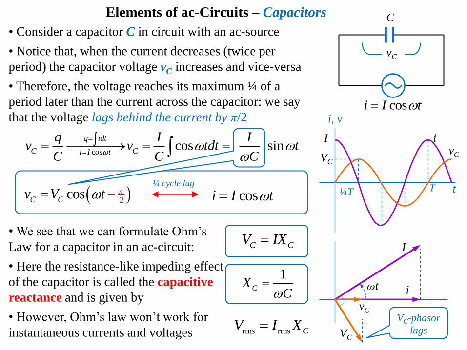
• Consider a capacitor C in circuit with an ac-source
• Notice that, when the current decreases (twice per
period) the capacitor voltage vC increases and vice-versa
• Therefore, the voltage reaches its maximum ¼ of a
period later than the current across the capacitor: we say
that the voltage lags behind the current by π/2
2 cosC Cv V t cosi I t
¼ cycle lag
Elements of ac-Circuits – Capacitors
1CX
C
• We see that we can formulate Ohm’s
Law for a capacitor in an ac-circuit:
• Here the resistance-like impeding effect
of the capacitor is called the capacitive
reactance and is given by
• However, Ohm’s law won’t work for
instantaneous currents and voltages
C CV IX
i vC
i, v
I
VC
t T
coscos sin
q idt
C Ci I t
q I Iv v tdt t
C C C
¼T
I
VC
i
vC
ωt
rms rms CV I XVC-phasor
lags
C
cosi I t
vC

vL
• Consider an inductor L in circuit with an ac-source
• The current in the circuit is impeded by the back emf
of the inductor
• As a result, the voltage across the inductor leads the
current by π/2:
LX L
rms rms LV I X
2 cosL Lv V t cosi I t
¼ cycle lead
Elements of ac-Circuits – Inductors
i vL
i, v
I
VL
t T ¼T
I VL
i
vL
ωt
sinL
div L LI t
dt
• Again, we can formulate Ohm’s Law
for an inductor in an ac-circuit:
• Here the resistance-like impeding effect
of the inductor is called the inductive
reactance and is given by
• However, Ohm’s law won’t work for
instantaneous currents and voltages
L LV IXVL-phasor
leads
L
cosi I t
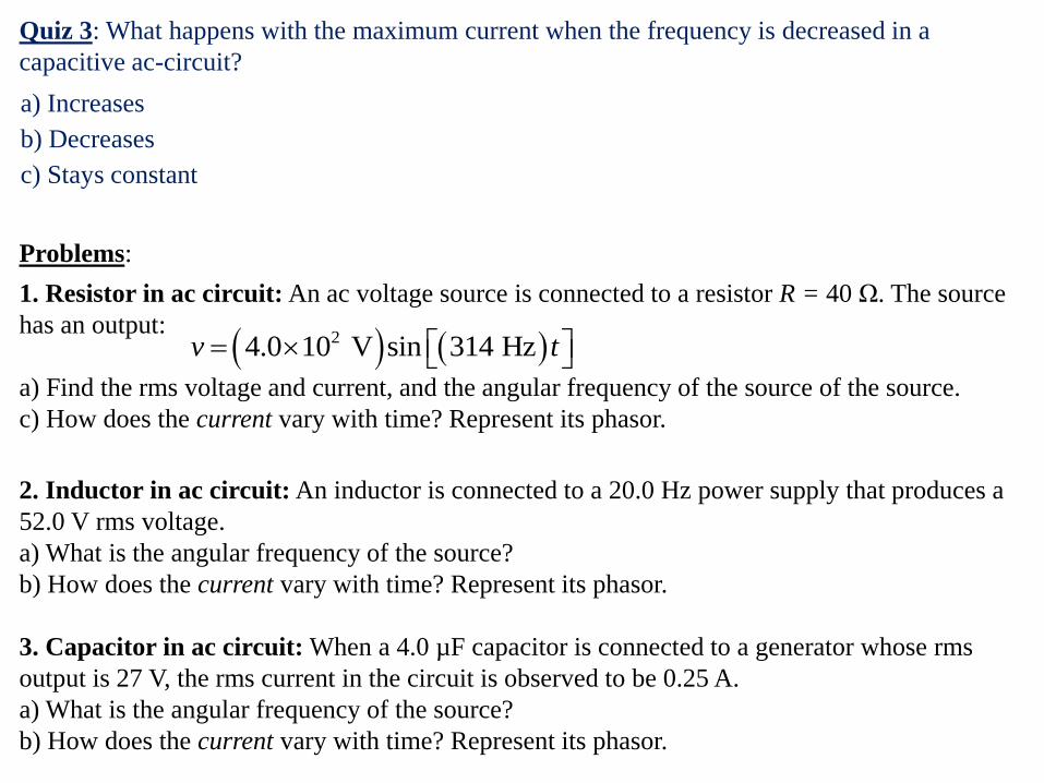
Problems:
1. Resistor in ac circuit: An ac voltage source is connected to a resistor R = 40 Ω. The source
has an output:
a) Find the rms voltage and current, and the angular frequency of the source of the source.
c) How does the current vary with time? Represent its phasor.
2. Inductor in ac circuit: An inductor is connected to a 20.0 Hz power supply that produces a
52.0 V rms voltage.
a) What is the angular frequency of the source?
b) How does the current vary with time? Represent its phasor.
3. Capacitor in ac circuit: When a 4.0 µF capacitor is connected to a generator whose rms
output is 27 V, the rms current in the circuit is observed to be 0.25 A.
a) What is the angular frequency of the source?
b) How does the current vary with time? Represent its phasor.
24.0 10 V sin 314 Hzv t
Quiz 3: What happens with the maximum current when the frequency is decreased in a
capacitive ac-circuit?
a) Increases
b) Decreases
c) Stays constant
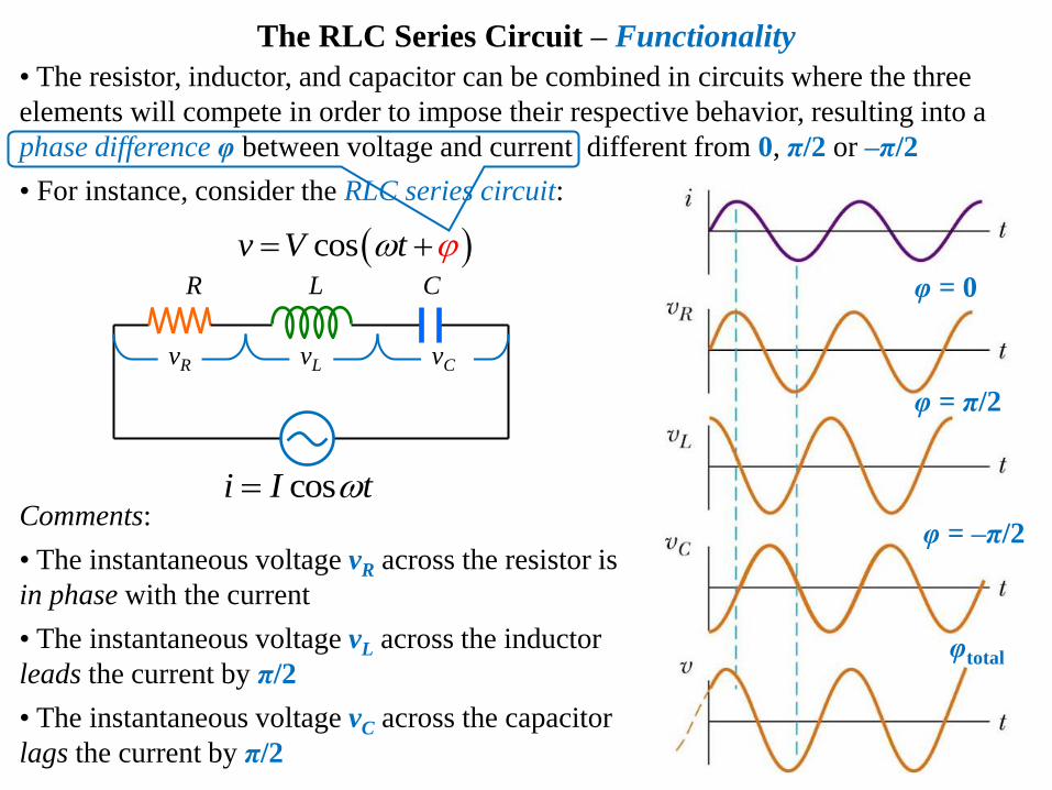
The RLC Series Circuit – Functionality
• The resistor, inductor, and capacitor can be combined in circuits where the three
elements will compete in order to impose their respective behavior, resulting into a
phase difference φ between voltage and current different from 0, π/2 or –π/2
• For instance, consider the RLC series circuit:
Comments:
• The instantaneous voltage vR across the resistor is
in phase with the current
• The instantaneous voltage vL across the inductor
leads the current by π/2
• The instantaneous voltage vC across the capacitor
lags the current by π/2
cosi I t
cosv V t
φ = 0
φ = π/2
φ = –π/2
φtotal
L
vL
R
vR vC
C

Let’s build the phasor diagram for an RLC series circuit
contains the voltage phasors on the same diagram with a
reference current
• The voltage across the resistor is along the current
phasor since it is in phase with the current
• The voltage across the inductor is perpendicular
anticlockwise on the current phasor since it leads the
current by π/2
• The voltage across the capacitor is perpendicular
clockwise on the current phasor since it lags behind the
current by π/2
• Since the voltages are not in phase, to get the voltage
across the combination of elements we can add the
phasors like vectors:
where φ is the phase angle between the net voltage and
current, since VR has the same phase as the current
I
VC = IXC
If XL > XC such that VL > VC, the
voltage leads the current by φ
The RLC Series Circuit – Phasor diagram
cosi I t
L R C
VL – VC
φ
VL = IXL
VR = IR
V = IZ
I VL = IXL
VC – VL
φ
VC = IXC
VR = IR
V = IZ
If XL < XC such that VL < VC, the
voltage lags the current by φ
22
R L CV V V V 1tan L C
R
V V
V

• The resistance of a circuit determining the ac current is given by its impedance Z
• To find the impedance and phase, we can use the phasor diagram and Ohm’s law:
• So, Ohm’s Law can also be applied to the whole RLC circuit:
where the impedance for RLC series can be rewritten
Impedance of series ac-Circuits
rms rmsV IZ V I Z
22 L CV I R X X IZ
2
2 1 RZ L
C
1tan L CX X
R
• This form for Ohm’s law can
be regarded as a generalized
form applied to any ac-circuit
even though the impedance may
have a different form than the
one of a series ac-combination
•The results can be extrapolated
to variants of the RLC series
circuit:
0
–π/2
π/2
–π/2
π/2 0

Power in ac-Circuits
• Single capacitors and inductors in ac-circuits are associated with no power losses:
• In a capacitor, energy is stored during one-half of a cycle and returned and
returned to the circuit during the other half
• In an inductor, the ac-source does work against the back emf of the inductor
and energy is stored in the inductor, but when the current begins to decrease in
the circuit, the energy is returned to the circuit
• Therefore, the net average power delivered by the ac-generator is converted to
internal energy in the resistor
• Consequently, the average power dissipated in a generic ac-circuit is
where cos φ is called the power factor of the circuit
• So, we see that phase shifts can be used to maximize power outputs, by making the
power factor 1
1av rms rms2
cos cosP IV P I V
2
av
1 2
cos cos cos cosP vi VI t t VI t
I
φ Vcosφ
V
ωt

Resonance in an ac-Circuit
• The resonance of an ac-circuit occurs at a certain
frequency ω0 where the current takes an extreme
value for the respective arrangement of elements
• For instance, in a series RLC, the resonance is
achieved when the current reaches a maximum which
occurs when the impedance has a minimum value
• Based on the expression for impedance, we get
22
series min RLC L CZ R X X Z R
0 0
0
1 1 L
C LC
Ex: a) Tuning a radio: a varying capacitor changes the resonance frequency of the tuning
circuit in your radio to match the station to be received
b) Metal Detector: The portal is an inductor, and the frequency is set to a condition with
no metal present. When a metal is present, it changes the effective inductance, which
changes the current. The change in current is detected and an alarm sounds
• This occurs when XL = XC, such that the resonance
frequency ω0 for the RLC series circuit is given by:
• Theoretically, if R = 0, the current would be infinite at
resonance, but real circuits always have some resistance
v lags i v leads i
v in phase with i

cosv V t
cosv V t
L
R
C Problem:
4. Parallel RLC circuit: A resistor R, a capacitor C and an inductor L
are connected in parallel across an ac source that provides a voltage
a) What are the phases of the currents through each element with respect
to v?
b) Use the respective current phasors to find out the current i through the
source in terms of the currents through the elements and the phase angle
with respect to v.
c) Find the impedance of the circuit
d) Calculate the respective resonance angular frequency ω0 and the angle
phase φ0 for this frequency. Then calculate the minimum current I0.

Transformers – Properties
• An ac-transformer consists of two coils of
wire wound around a core of soft iron
• The side connected to the input AC voltage
source is called the primary and has N1 turns
• The other side, called the secondary, is
connected to a resistor and has N2 turns
• The core is used to increase the magnetic flux
and to provide a medium for the flux to pass
from one coil to the other
• When N2 > N1 ↔ V2 > V1 the transformer is called a step up transformer
• When N2 < N1 ↔ V2 < V1 the transformer is called a step down transformer
22 1
1
NV
NV 1
2 1
2
NI
NI2 2 1 1I V I V
Symbol:
Properties:
1. The rate of change of the magnetic flux
is the same through both coils, such that
the potential differences across the
primary and secondary are related by
1 11 2
2 2
B B
t t
NN N
N
2. On the other hand, the energy must be
conserved, so the power input and output
must be the same, such that the primary
and secondary currents are related by
33.7

Application:
• When transmitting electric power over long distances, it is most economical to use
high voltage and low current since this minimizes the I2R power losses
• In practice, voltage is stepped up to about 230 000 V at the generating station and
stepped down to 20 000 V at the distribution station and finally to 120 V at the
customer’s utility pole
Transformers – Comments and an important application
• While ideally the energy is conserved across a transformer and the only energy loss
is via resistive dissipation, in reality a transformer also loses energy due to eddy
currents in the iron core
Comments:
• Besides voltages and currents, the
transformer also “transforms” impedance: 1 1 2 2
2
1 2 1 2 2 1
V N N V Z
I N N I N N
• A modern solution to this loss of energy is to use superconductive cables that would
reduce the resistance rather than current

Problem:
5. Transformer in an ac-circuit: A transformer is to be used to provide power for a computer
disk drive that needs 5.8 V (rms) instead of the 120 V (rms) from the wall outlet. The number
of turns in the primary is 400, and it delivers 500 mA (the secondary current) at an output
voltage of 5.8 V (rms).
a) Should the transformer have more turns in the secondary compared to the primary, or fewer
turns?
b) Find the current in the primary.
c) Find the number of turns in the secondary.