Embed Size (px)
Citation preview
International Journal of Advancements in Research & Technology, Volume 2, Issue 5, May-2013 502 ISSN 2278-7763
Copyright © 2013 SciResPub. IJOART
Versatile Ultra High Vacuum System for ION Trap Experiments: Design and Implementation
Altaf H. Nizamani1, Muhammad A. Rind1, Nek Muhammad Shaikh1, Akhtar H. Moghal1, Hussain Saleem2 1 Institute of Physics, University of Sindh, Jamshoro, 76080, Pakistan
2 Department of Computer Science, University of Karachi, Karachi, 75270, Pakistan Email: [email protected], [email protected], [email protected], [email protected], [email protected] ABSTRACT This paper presents an ultra high vacuum system for ion trap experiments which provides a pressure down to order of 10-12 torr. In order to host ion traps and trap chip carriers, the system includes a custom mounting bracket having above 90 electrical con-nections. Versatile optical access for many types of traps including those traps which require laser access via a through hole as well as for those traps which require laser beams parallel to the surface of the trap is ensured via nine viewports in the system. The chip carriers can be easily mounted onto the mounting bracket and can also be replaced with minimal turnaround time when required. For both through hole and parallel surface trap geometries, four atomic-ovens are mounted on the bracket inside the chamber to cater the atomic vapours for trapping purpose. Keywords : Ultra High Vacuum, Ion traps, microfabricated ion trap chips, quantum technology, LASER cooling and trapping
1 INTRODUCTION ONS trapped in radio-frequency Paul traps are considered as one of the most promising approaches to implement quantum information technology, as well as for quantum
simulators and frequency standards [1],[2],[3],[4]. Realizing the experimental setups for ion trap experiments is always considered a challenging task. State-of-the art technology is required to implement ion trap experiments. The building block of ion trap experiments is a vacuum system in which a low pressure on the order of 10-12 torr is required in order to isolate the trapped ions from surrounding background atoms in ion trap experiments [5]. This isolation is necessary to pre-vent background collisions destroying the quantum state of the qubit or knock the ion out of the trapping region. At this pressure, the mean free path reaches 104 km, hence the colli-sion rate between the residual atoms and trapped ions inside the vacuum chamber drops significantly, and ions can remain trapped for a time of a few hours to a few days.
The UHV system is able to produce and sustain a pressure of 10-12 torr and provide laser access for different types of ion trap geometries. Furthermore, in order to investigate various ion trap geometries to determine which is more feasible for scalable quantum computing, the vacuum chamber is capable of accommodating different trap geometries and provides la-ser access along different axes for the traps. For this to ensure, the system includes a customise chip mounting bracket with 90 electrical connections.
In vacuum terminology, the outgassing process controls the ultimate pressure in high and Ultra High Vacuum systems (UHV) [6]. The desorption of gases are the major source of outgassing in a well designed ultra high vacuum system and can be reduced by baking the vacuum parts at certain temper-ature for a period of at least two weeks. The materials used in the UHV system have negligible vapour pressures. Care must
be taken in the selection of materials used for ion traps. Lists of low outgassing materials are widely available [7].
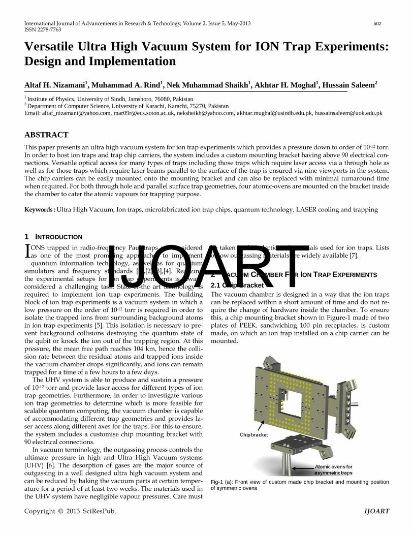
2 VACUUM CHAMBER FOR ION TRAP EXPERIMENTS 2.1 Chip Bracket The vacuum chamber is designed in a way that the ion traps can be replaced within a short amount of time and do not re-quire the change of hardware inside the chamber. To ensure this, a chip mounting bracket shown in Figure-1 made of two plates of PEEK, sandwiching 100 pin receptacles, is custom made, on which an ion trap installed on a chip carrier can be mounted.
Fig-1 (a): Front view of custom made chip bracket and mounting position of symmetric ovens
I IJOART
International Journal of Advancements in Research & Technology, Volume 2, Issue 5, May-2013 503 ISSN 2278-7763
Copyright © 2013 SciResPub. IJOART
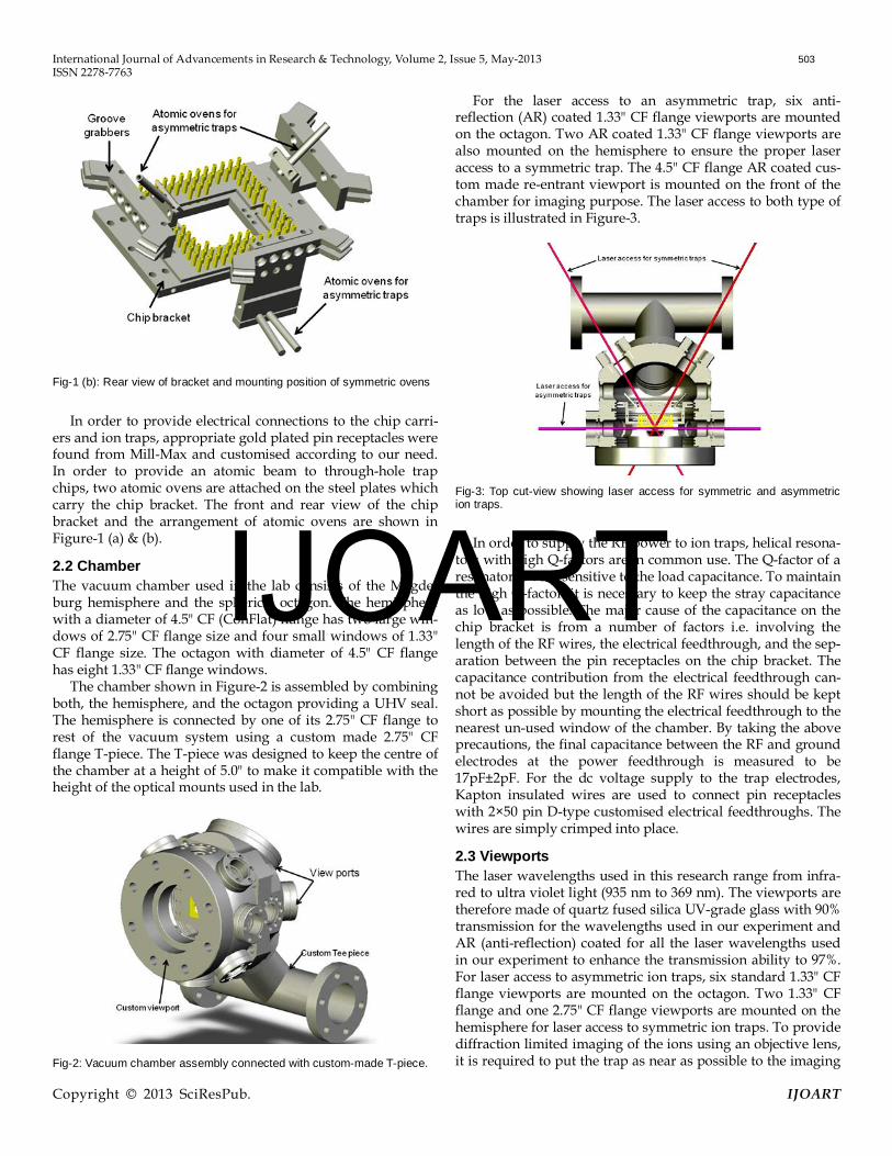
Fig-1 (b): Rear view of bracket and mounting position of symmetric ovens
In order to provide electrical connections to the chip carri-ers and ion traps, appropriate gold plated pin receptacles were found from Mill-Max and customised according to our need. In order to provide an atomic beam to through-hole trap chips, two atomic ovens are attached on the steel plates which carry the chip bracket. The front and rear view of the chip bracket and the arrangement of atomic ovens are shown in Figure-1 (a) & (b).
2.2 Chamber The vacuum chamber used in the lab consists of the Magde-burg hemisphere and the spherical octagon. The hemisphere with a diameter of 4.5" CF (ConFlat) flange has two large win-dows of 2.75" CF flange size and four small windows of 1.33" CF flange size. The octagon with diameter of 4.5" CF flange has eight 1.33" CF flange windows.
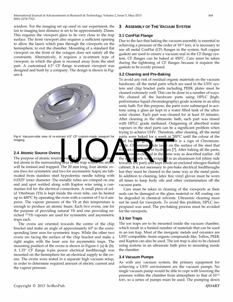
The chamber shown in Figure-2 is assembled by combining both, the hemisphere, and the octagon providing a UHV seal. The hemisphere is connected by one of its 2.75" CF flange to rest of the vacuum system using a custom made 2.75" CF flange T-piece. The T-piece was designed to keep the centre of the chamber at a height of 5.0" to make it compatible with the height of the optical mounts used in the lab.
Fig-2: Vacuum chamber assembly connected with custom-made T-piece.
For the laser access to an asymmetric trap, six anti-reflection (AR) coated 1.33" CF flange viewports are mounted on the octagon. Two AR coated 1.33" CF flange viewports are also mounted on the hemisphere to ensure the proper laser access to a symmetric trap. The 4.5" CF flange AR coated cus-tom made re-entrant viewport is mounted on the front of the chamber for imaging purpose. The laser access to both type of traps is illustrated in Figure-3.
Fig-3: Top cut-view showing laser access for symmetric and asymmetric ion traps.
In order to supply the RF power to ion traps, helical resona-tors with high Q-factors are in common use. The Q-factor of a resonator is very sensitive to the load capacitance. To maintain the high Q-factor, it is necessary to keep the stray capacitance as low as possible. The major cause of the capacitance on the chip bracket is from a number of factors i.e. involving the length of the RF wires, the electrical feedthrough, and the sep-aration between the pin receptacles on the chip bracket. The capacitance contribution from the electrical feedthrough can-not be avoided but the length of the RF wires should be kept short as possible by mounting the electrical feedthrough to the nearest un-used window of the chamber. By taking the above precautions, the final capacitance between the RF and ground electrodes at the power feedthrough is measured to be 17pF±2pF. For the dc voltage supply to the trap electrodes, Kapton insulated wires are used to connect pin receptacles with 2×50 pin D-type customised electrical feedthroughs. The wires are simply crimped into place.
2.3 Viewports The laser wavelengths used in this research range from infra-red to ultra violet light (935 nm to 369 nm). The viewports are therefore made of quartz fused silica UV-grade glass with 90% transmission for the wavelengths used in our experiment and AR (anti-reflection) coated for all the laser wavelengths used in our experiment to enhance the transmission ability to 97%. For laser access to asymmetric ion traps, six standard 1.33" CF flange viewports are mounted on the octagon. Two 1.33" CF flange and one 2.75" CF flange viewports are mounted on the hemisphere for laser access to symmetric ion traps. To provide diffraction limited imaging of the ions using an objective lens, it is required to put the trap as near as possible to the imaging
IJOART
International Journal of Advancements in Research & Technology, Volume 2, Issue 5, May-2013 504 ISSN 2278-7763
Copyright © 2013 SciResPub. IJOART
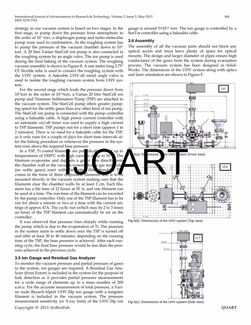
window. For the imaging set up used in our experiment, the ion to imaging lens distance is set to be approximately 23mm. This requires the viewport glass to be very close to the trap surface. The front viewport also requires a sufficient opening to allow the lasers which pass through the viewports on the hemisphere, to exit the chamber. Mounting of a standard flat viewport on the front of the octagon does not satisfy all the constraints. Alternatively, it requires a re-entrant type of viewport, in which the glass is recessed away from the steel part. A customised 4.5" CF flange re-entrant viewport was designed and built by a company. The design is shown in Fig-ure-4.
Fig-4: Vacuum-side view of re-entrant 4.5” CF custom-made viewport for imaging.
2.4 Atomic Source Ovens The purpose of atomic source ovens is to create a beam of neu-tral atoms in the surrounding area of the trap where the atoms will be ionised and trapped. The 20 mm long, four atomic ov-ens (two for symmetric and two for asymmetric traps) are fab-ricated from stainless steel hypodermic needle tubing with 0.0325" inner diameter. The metallic tubes are crimped on one end and spot welded along with Kapton wire using a con-stantan foil for the electrical connections. A small piece of sol-id Ytterbium (Yb) is kept inside the oven tube, can be heated up to 400°C by operating the oven with a current of 5 to 6 am-peres. The vapour pressure of the Yb at this temperature is enough to produce an atomic beam. Each two ovens, one for the purpose of providing natural Yb and one providing en-riched 171Yb vapours are used for symmetric and asymmetric traps each.
The ovens are oriented towards the centre of the chip bracket and make an angle of approximately 63° to the corre-sponding laser axes for symmetric traps. While the other two ovens are facing the surface of the chip bracket and make a right angles with the laser axis for asymmetric traps. The mounting position of the ovens is shown in Figure-1 (a) & (b). A 1.33" CF flange 6-pin power electrical feedthrough was mounted on the hemisphere for an electrical supply to the ov-ens. The ovens were tested in a separate high vacuum setup, in order to determine required amount of electric current and the vapour pressure.
3 ASSEMBLY OF THE VACUUM SYSTEM
3.1 ConFlat Flange Due to the fact that baking the vacuum assembly is essential to achieving a pressure of the order of 10-12 torr, it is necessary to use all metal ConFlat (CF) flanges in the system. Soft copper gaskets are used to ensure a vacuum seal in the CF flange sys-tem. CF flanges can be baked at 450°C. Care must be taken during the tightening of CF flanges because it requires the gaskets to be evenly pressed.
3.2 Cleaning and Pre-Baking To avoid any risk of residual organic materials on the vacuum hardware, all the metal parts which are used in the UHV sys-tem and chip bracket parts including PEEK plates must be cleaned extremely well. This can be done in a number of ways. We cleaned all the hardware parts using HPLC (high-performance liquid chromatography) grade acetone in an ultra sonic bath. For this purpose, the parts were submerged in ace-tone using a glass jar kept in a water filled tank of the ultra-sonic cleaner. Each part was cleaned for at least 10 minutes. After cleaning in the ultrasonic bath, each part was rinsed with HPLC grade methanol. Outgassing of absorbed water vapours in the steel parts can be a significant problem when trying to achieve UHV. Therefore, after cleaning, all the metal parts were baked for a week at 200°C until the colour of the steel became golden brown which is a sign of Chromium-oxide. Chromium-oxide layer on the surface of the steel that reduces outgassing of hydrogen [7]. After baking all the parts, they were re-cleaned in the same way as described earlier. All the metal parts were wrapped in an aluminum foil (shiny side towards the part) and kept inside an enclosed nitrogen flushed cabinet. It is not necessary to pre-bake electrical feedthroughs but they must be cleaned in the same way as the metal parts. In addition to cleaning, latex free vinyl gloves must be worn all times to keep body oils and other contamination off the vacuum parts.
Care must be taken in cleaning of the viewports as their seals can be damaged or the glass material or AR coating can be degraded in chemical solvents. Ultrasonic cleaning must not be used for viewports. To avoid this problem, HPLC iso-propanol was used. The pre-baking process must be avoided for the viewports.
3.3 Ion Traps The ion traps are to be mounted inside the vacuum chamber, which result in a limited number of materials that can be used in an ion trap. Most of the inorganic metals and ceramics are UHV compatible. Some organic compounds like, Teflon, PEEK and Kapton can also be used. The ion trap is also to be cleaned using acetone in an ultrasonic bath prior to mounting inside the chamber.
3.4 Vacuum Pumps As with any vacuum system, the primary equipment for achieving a UHV environment are the vacuum pumps. No single vacuum pump would be able to cope with lowering the pressure within the chamber from atmosphere to that of 10-12 torr, so a series of pumps must be used. The pumping down
IJOART
International Journal of Advancements in Research & Technology, Volume 2, Issue 5, May-2013 505 ISSN 2278-7763
Copyright © 2013 SciResPub. IJOART
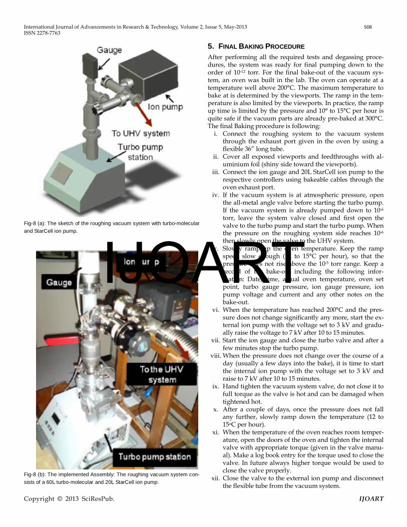
strategy in our vacuum system is based on two stages. In the first stage, to pump down the pressure from atmospheric to the order of 10-7 torr, a diaphragm pump and turbo-molecular pump were used in combination. As the roughing system has to pump the pressure of the vacuum chamber down to 10-7 torr. A 20 litre Varian StarCell ion pump is also connected in the roughing system by an angle valve. The ion pump is used during the final baking of the vacuum system. The roughing vacuum assembly is shown in Figure-8. A one metre long 2.75" CF flexible tube is used to connect the roughing system with the UHV system. A bakeable UHV-all metal angle valve is used to isolate the roughing vacuum system from UHV sys-tem.
For the second stage which leads the pressure down from 10-7torr to the order of 10-12torr, a Varian 20 litre StarCell ion pump and Titanium Sublimation Pump (TSP) are attached to the vacuum system. The StarCell pump offers greater pump-ing speed for the noble gases than any other kind of ion pump. The StarCell ion pump is connected with the pump controller using a bakeable cable. A high power current controller with an automatic on/off timer was used to supply a high current to TSP filaments. TSP pumps run for a short time (approx 1 to 2 minutes). There is no need for a bakeable cable for the TSP, as it only runs for a couple of days for short time intervals af-ter the baking procedure or whenever the pressure in the sys-tem rises above the required base pressure.
In a TSP, Ti coated filaments are periodically heated up to temperatures of 1500°C with high currents of up to 50 A. The titanium evaporates and deposits a getter film directly onto the chamber wall in the vacuum system. Active gas molecules (no noble gases) react with the getter film. Standard TSP comes in the form of three disposable filaments and is to be mounted directly in the vacuum system making sure that the filaments clear the chamber walls by at least 2 cm. Each fila-ment has a life time of 12 hours at 50 A, and one filament can be used at a time. The run-time of the filament can be recorded by the pump controller. Only one of the TSP filament has to be run for about a minute or two at a time with the current set-tings of approx 47A. The cyclic run (which may be 2 to 3 times an hour) of the TSP filament can automatically be set on the controller.
It was observed that pressure rises sharply while running the pump which is due to the evaporation of Ti. The pressure in the system starts to settle down once the TSP is turned off and after at least 30 to 40 minutes, depending on the running time of the TSP, the base pressure is achieved. After each run-ning cycle, the final base pressure would be less than the pres-sure achieved in the previous cycle.
3.5 Ion Gauge and Residual Gas Analyzer To monitor the vacuum pressure and partial pressure of gases in the system, ion gauges are required. A Residual Gas Ana-lyser (from Extorr) is included in the system for the purpose of leak detection as it provides partial pressure measurements for a wide range of elements up to a mass number of 200 a.m.u. For the accurate measurement of total pressure, a Vari-an nude Bayard-Alpert UHV-24p ion gauge with a tungsten filament is included in the vacuum system. The pressure measurement sensitivity (or X-ray limit) of the UHV-24p ion
gauge is around 5×10-12 torr. The ion gauge is controlled by a SenTor controller using a bakeable cable.
3.6 Assembly The assembly of all the vacuum parts should not block any optical access and must leave plenty of space for optical mounts. The design and larger diameter of pipes ensure high conductance of the gases from the system during evacuation process. The vacuum system has been designed in Solid-Works. The dimensions of the UHV system along with optics and laser orientation are shown in Figure-5.
Fig-5(a): Dimensions of the UHV system (Front view)
Fig-5(b): Dimensions of the UHV system (Top view)
Fig-5(c): Dimensions of the UHV system (Side view)
IJOART
International Journal of Advancements in Research & Technology, Volume 2, Issue 5, May-2013 506 ISSN 2278-7763
Copyright © 2013 SciResPub. IJOART
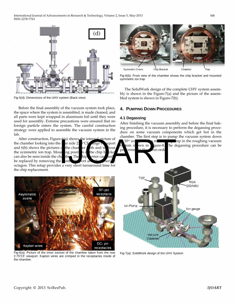
Fig-5(d): Dimensions of the UHV system (Back view)
Before the final assembly of the vacuum system took place, the space where the system is assembled, is made cleaned, and all parts were kept wrapped in aluminum foil until they were used for assembly. Extreme precautions were ensured that no foreign particle enters the system. The careful construction strategy were applied to assemble the vacuum system in the lab.
After construction, Figure-6(a) shows the internal picture of the chamber looking into the rear side 2.75"CF flange viewport and 6(b) shows the pictures of the chamber with and without the symmetric ion trap. Mounting position of the chip bracket can also be seen inside the chamber. The chip carrier can easily be replaced by removing the front viewport and the spherical octagon. This setup provides a very short turnaround time for the chip replacement.
Fig-6(a): Picture of the inner section of the chamber taken from the rear 2.75”CF viewport. Kapton wires are crimped in the receptacles inside of the chamber.
Fig-6(b): Front view of the chamber shows the chip bracket and mounted symmetric ion trap
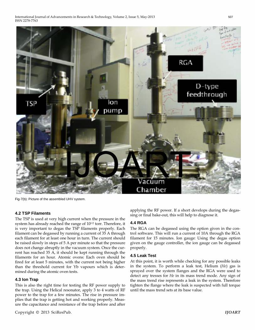
The SolidWork design of the complete UHV system assem-bly is shown in the Figure-7(a) and the picture of the assem-bled system is shown in Figure-7(b).
4. PUMPING DOWN PROCEDURES
4.1 Degassing After finishing the vacuum assembly and before the final bak-ing procedure, it is necessary to perform the degassing proce-dure on some vacuum components which get hot in the chamber. The first step is to pump the vacuum system down to 10-6 using a turbo molecular pump in the roughing vacuum system shown in Figure-8. The degassing procedure can be performed in the given order.
Fig-7(a): SolidWork design of the UHV System
IJOART
International Journal of Advancements in Research & Technology, Volume 2, Issue 5, May-2013 507 ISSN 2278-7763
Copyright © 2013 SciResPub. IJOART
Fig-7(b): Picture of the assembled UHV system.
4.2 TSP Filaments The TSP is used at very high current when the pressure in the system has already reached the range of 10-12 torr. Therefore, it is very important to degas the TSP filaments properly. Each filament can be degassed by running a current of 35 A through each filament for at least one hour in turn. The current should be raised slowly in steps of 5 A per minute so that the pressure does not change abruptly in the vacuum system. Once the cur-rent has reached 35 A, it should be kept running through the filaments for an hour. Atomic ovens: Each oven should be fired for at least 5 minutes, with the current not being higher than the threshold current for Yb vapours which is deter-mined during the atomic oven tests.
4.3 Ion Trap This is also the right time for testing the RF power supply to the trap. Using the Helical resonator, apply 3 to 4 watts of RF power to the trap for a few minutes. The rise in pressure im-plies that the trap is getting hot and working properly. Meas-ure the capacitance and resistance of the trap before and after
applying the RF power. If a short develops during the degas-sing or final bake-out, this will help to diagnose it.
4.4 RGA The RGA can be degassed using the option given in the con-trol software. This will run a current of 10A through the RGA filament for 15 minutes. Ion gauge: Using the degas option given on the gauge controller, the ion gauge can be degassed properly.
4.5 Leak Test At this point, it is worth while checking for any possible leaks in the system. To perform a leak test, Helium (He) gas is sprayed over the system flanges and the RGA were used to detect any tresses for He in its mass trend mode. Any sign of the mass trend rise represents a leak in the system. Therefore tighten the flange where the leak is suspected with full torque until the mass trend sets at its base value.
IJOART
International Journal of Advancements in Research & Technology, Volume 2, Issue 5, May-2013 508 ISSN 2278-7763
Copyright © 2013 SciResPub. IJOART
Fig-8 (a): The sketch of the roughing vacuum system with turbo-molecular and StarCell ion pump.
Fig-8 (b): The implemented Assembly: The roughing vacuum system con-sists of a 60L turbo-molecular and 20L StarCell ion pump.
5. FINAL BAKING PROCEDURE After performing all the required tests and degassing proce-dures, the system was ready for final pumping down to the order of 10-12 torr. For the final bake-out of the vacuum sys-tem, an oven was built in the lab. The oven can operate at a temperature well above 200°C. The maximum temperature to bake at is determined by the viewports. The ramp in the tem-perature is also limited by the viewports. In practice, the ramp up time is limited by the pressure and 10° to 15°C per hour is quite safe if the vacuum parts are already pre-baked at 300°C. The final Baking procedure is following:
i. Connect the roughing system to the vacuum system through the exhaust port given in the oven by using a flexible 36” long tube.
ii. Cover all exposed viewports and feedthroughs with al-uminium foil (shiny side toward the viewports).
iii. Connect the ion gauge and 20L StarCell ion pump to the respective controllers using bakeable cables through the oven exhaust port.
iv. If the vacuum system is at atmospheric pressure, open the all-metal angle valve before starting the turbo pump. If the vacuum system is already pumped down to 10-6 torr, leave the system valve closed and first open the valve to the turbo pump and start the turbo pump. When the pressure on the roughing system side reaches 10-6 then slowly open the valve to the UHV system.
v. Slowly ramp up the oven temperature. Keep the ramp speed slow enough (12 to 15°C per hour), so that the pressure does not rise above the 10-5 torr range. Keep a record of the bake-out including the following infor-mation: Date, time, actual oven temperature, oven set point, turbo gauge pressure, ion gauge pressure, ion pump voltage and current and any other notes on the bake-out.
vi. When the temperature has reached 200°C and the pres-sure does not change significantly any more, start the ex-ternal ion pump with the voltage set to 3 kV and gradu-ally raise the voltage to 7 kV after 10 to 15 minutes.
vii. Start the ion gauge and close the turbo valve and after a few minutes stop the turbo pump.
viii. When the pressure does not change over the course of a day (usually a few days into the bake), it is time to start the internal ion pump with the voltage set to 3 kV and raise to 7 kV after 10 to 15 minutes.
ix. Hand tighten the vacuum system valve, do not close it to full torque as the valve is hot and can be damaged when tightened hot.
x. After a couple of days, once the pressure does not fall any further, slowly ramp down the temperature (12 to 15oC per hour).
xi. When the temperature of the oven reaches room temper-ature, open the doors of the oven and tighten the internal valve with appropriate torque (given in the valve manu-al). Make a log book entry for the torque used to close the valve. In future always higher torque would be used to close the valve properly.
xii. Close the valve to the external ion pump and disconnect the flexible tube from the vacuum system.
IJOART
International Journal of Advancements in Research & Technology, Volume 2, Issue 5, May-2013 509 ISSN 2278-7763
Copyright © 2013 SciResPub. IJOART
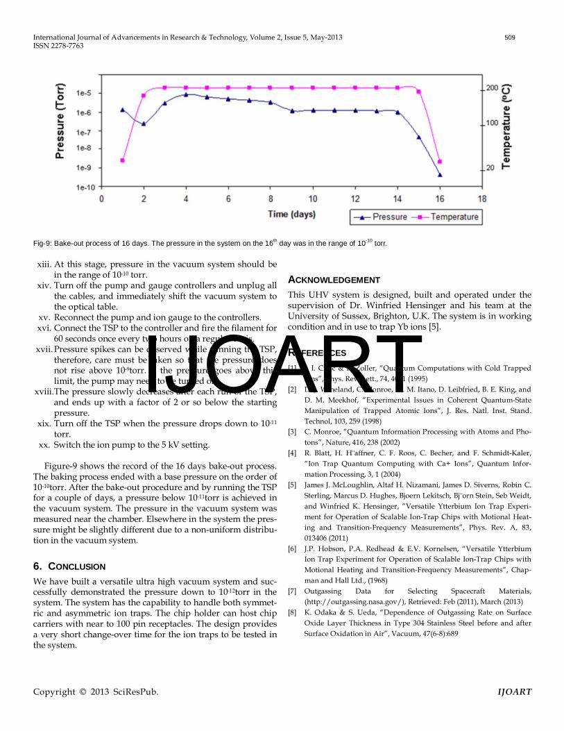
Fig-9: Bake-out process of 16 days. The pressure in the system on the 16th day was in the range of 10-10 torr. xiii. At this stage, pressure in the vacuum system should be
in the range of 10-10 torr. xiv. Turn off the pump and gauge controllers and unplug all
the cables, and immediately shift the vacuum system to the optical table.
xv. Reconnect the pump and ion gauge to the controllers. xvi. Connect the TSP to the controller and fire the filament for
60 seconds once every two hours on a regular basis. xvii. Pressure spikes can be observed while running the TSP,
therefore, care must be taken so that the pressure does not rise above 10-9torr. If the pressure goes above this limit, the pump may need to be turned off.
xviii. The pressure slowly decreases after each run of the TSP, and ends up with a factor of 2 or so below the starting pressure.
xix. Turn off the TSP when the pressure drops down to 10-11
torr. xx. Switch the ion pump to the 5 kV setting.
Figure-9 shows the record of the 16 days bake-out process.
The baking process ended with a base pressure on the order of 10-10torr. After the bake-out procedure and by running the TSP for a couple of days, a pressure below 10-11torr is achieved in the vacuum system. The pressure in the vacuum system was measured near the chamber. Elsewhere in the system the pres-sure might be slightly different due to a non-uniform distribu-tion in the vacuum system.
6. CONCLUSION We have built a versatile ultra high vacuum system and suc-cessfully demonstrated the pressure down to 10-12torr in the system. The system has the capability to handle both symmet-ric and asymmetric ion traps. The chip holder can host chip carriers with near to 100 pin receptacles. The design provides a very short change-over time for the ion traps to be tested in the system.
ACKNOWLEDGEMENT This UHV system is designed, built and operated under the supervision of Dr. Winfried Hensinger and his team at the University of Sussex, Brighton, U.K. The system is in working condition and in use to trap Yb ions [5].
REFERENCES [1] J. I. Cirac & P. Zoller, “Quantum Computations with Cold Trapped
Ions”, Phys. Rev. Lett., 74, 4091 (1995) [2] D. J. Wineland, C. Monroe, W. M. Itano, D. Leibfried, B. E. King, and
D. M. Meekhof, “Experimental Issues in Coherent Quantum-State Manipulation of Trapped Atomic Ions”, J. Res. Natl. Inst. Stand. Technol, 103, 259 (1998)
[3] C. Monroe, “Quantum Information Processing with Atoms and Pho-tons”, Nature, 416, 238 (2002)
[4] R. Blatt, H. H¨affner, C. F. Roos, C. Becher, and F. Schmidt-Kaler, “Ion Trap Quantum Computing with Ca+ Ions”, Quantum Infor-mation Processing, 3, 1 (2004)
[5] James J. McLoughlin, Altaf H. Nizamani, James D. Siverns, Robin C. Sterling, Marcus D. Hughes, Bjoern Lekitsch, Bj¨orn Stein, Seb Weidt, and Winfried K. Hensinger, “Versatile Ytterbium Ion Trap Experi-ment for Operation of Scalable Ion-Trap Chips with Motional Heat-ing and Transition-Frequency Measurements”, Phys. Rev. A, 83, 013406 (2011)
[6] J.P. Hobson, P.A. Redhead & E.V. Kornelsen, “Versatile Ytterbium Ion Trap Experiment for Operation of Scalable Ion-Trap Chips with Motional Heating and Transition-Frequency Measurements”, Chap-man and Hall Ltd., (1968)
[7] Outgassing Data for Selecting Spacecraft Materials, (http://outgassing.nasa.gov/), Retrieved: Feb (2011), March (2013)
[8] K. Odaka & S. Ueda, “Dependence of Outgassing Rate on Surface Oxide Layer Thickness in Type 304 Stainless Steel before and after Surface Oxidation in Air”, Vacuum, 47(6-8):689
IJOART
International Journal of Advancements in Research & Technology, Volume 2, Issue 5, May-2013 510 ISSN 2278-7763
Copyright © 2013 SciResPub. IJOART
Altaf Hussain Nizamani is working as Assistant Professor at the Institute of Physics, University of Sindh, Jamshoro, Pakistan. He received Ph.D degree in Ion-Trapping and Quantum computa-tion technology from the University of Sussex, Brighton, UK in 2011. His areas of interests are Scalable Ion trap chips for the quantum compu-ting and information technology, ultra high vac-uum system designing, FPGA and Real-time LabVIEW programming, LASER cooling & trap-ping and computational Physics.
Muhammad Akhter Rind is a Lecturer at the Institute of Physics, University of Sindh, Jams-horo, Pakistan. He is currently working as a postgraduate student and researcher at the Uni-versity of Southampton, UK. His area of research is “Thin Film Solar Cells”. He also took high interest in PECVD deposition of thin film solar cells, Individual fabrication of Amorphous and Micro-crystalline Silicon optimize layers, Germa-nium deposition via PECVD, Hotwire CVD dep-
osition, Silicon Oxide and Nitrite PECVD deposition, Process develop-ment of ITO via plasma assisted evaporation, Solar cell contact deposition via Evaporation, Metal Deposition (Al, Ag, Au, Sn Ti and others), Plasma and wet Etching, Rapid thermal annealing and Concentrated PV contact deposition.
Nek Muhammad Shaikh is an Associate Profes-sor at the Institute of Physic, University of Sindh, Jamshoro. He has completed his Ph.D. in Laser Spectroscopy, from the Atomic and Molecular Physics Laboratory, Department of Physics, Quaid-e-Azam University, Islamabad, Pakistan. He has also completed his Post-Doctorate from the Center for Energy Research, University of California, San Diego, California, USA, in 2009,
where he worked on the different experimental techniques to increase conversion efficiency of the Extreme Ultraviolet (EUV) light using lasers. His area of interests are Laser-Induced Breakdown Spectroscopy, Laser spectroscopy and Laser physics.
Akhtar Hussain Moghal is Professor and Director at the Institute of Physics, university of Sindh, Jamshoro, Pakistan. He was awarded Ph.D. in Experimental High Energy Physics in 1991 from Brunel University, London, UK, in the field of U.V. Photocathodes for Solid Scintillator Propor-tional Counter. He has completed number of re-search projects in the field of Gamma Radiation Detectors Prototype Photosensitive Multiwire
Proportional Counter. His areas of research are novel UV-sensitive, air-stable solid photocathodes for use in solid Scintillator, Proportional coun-ters, new Photocathodes for fast gaseous detectors, reflective UV Photo-cathodes for Position Sensitive Gaseous Detectors, invastigation of new low Ionization Potential Compounds as UV-Photocathodes in vacuum and gas media.
Hussain Saleem is Assistant Professor and Ph.D. Research Scholar at Department of Com-puter Science, University of Karachi, Pakistan. He received B.S. in Electronics Engineering from Sir Syed University of Engineering & Technology, Karachi in 1997 and has done Masters in Computer Science from University of Karachi in 2001. He also received Diploma in Statistics from University of Karachi in 2007. He bears vast experience of more than 16 years of University Teaching, Administration and
Research in various dimensions of Computer Science. Hussain is the Sen-ior Instructor and has been associated with the Physics Labs at Aga Khan Ex. Students Association Karachi since 1992. During his graduate study, he spent two years at Steel Mill Industry to learn the turbine processes, and extensively worked on Laser and Fiber Opto-Electronics. He also served as Bio-Medical Engineer at Aga Khan University in 1999-2000, where he practiced to handle Radiology and MRI equipments. Hussain is the Author of several International Journal publications. His field of inter-est is Software Science, System Automation, Hardware Design & Engi-neering, Data Analysis, and Simulation & Modeling. He is senior member of Pakistan Engineering Council (PEC).
IJOART